Embed Size (px)
Citation preview
7/30/2019 Presentation Pulse
http://slidepdf.com/reader/full/presentation-pulse 1/27
MOHD ZUBAIRY AZWAN BIN SHUKRY2009680176
SHAZARIN BIN KHALID2009818516

7/30/2019 Presentation Pulse
http://slidepdf.com/reader/full/presentation-pulse 2/27
SPARK GAP
7/30/2019 Presentation Pulse
http://slidepdf.com/reader/full/presentation-pulse 3/27
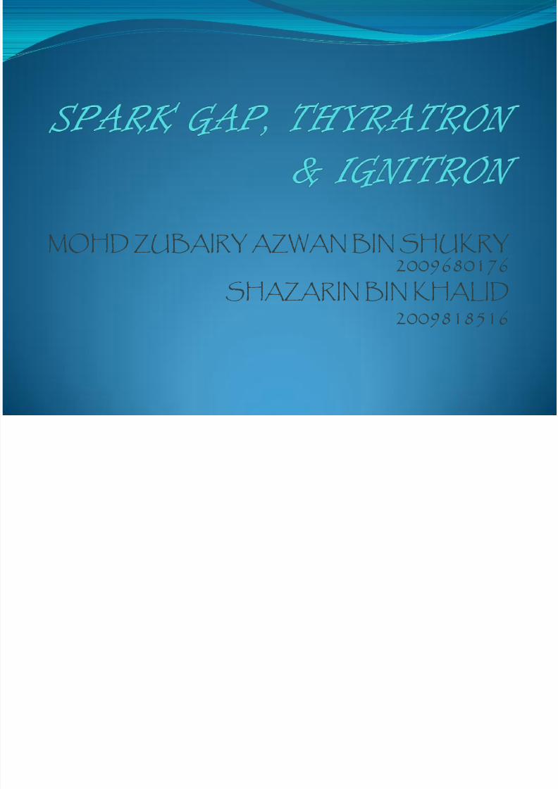
SPARK GAP A spark gap consists of an arrangement of two conducting electrodes
separated by a gap usually filled with a gas such as air, designed to allowan electric spark to pass between the conductors. When the voltagedifference between the conductors exceeds the gap's breakdown
voltage, a spark forms, ionizing the gas and drastically reducing itselectrical resistance.
7/30/2019 Presentation Pulse
http://slidepdf.com/reader/full/presentation-pulse 4/27
Recap
The breakdown voltage of an insulator is the minimum voltage that causes a portion of an insulator to becomeelectrically conductive.
Ionization is the process of converting an atom ormolecule into an ion by adding or removing chargedparticles such as electrons or ions.
7/30/2019 Presentation Pulse
http://slidepdf.com/reader/full/presentation-pulse 5/27
History
David Hughes, a British scientist was discovered partially by accident the spark gap transmitter when he made severalimprovements to the wired telegraph but he never publishedhis findings.
Heinrich Hertz to produce his own spark gap transmitter andreceiver in 1886. Hertz also verified that the spark gap producedelectromagnetic waves.
Nikola Tesla further improved the technology by devising atransmission and receiving system that could be roughly tuned.
By 1895, Guglielmo Marconi was able to transmit a signal andreceive it almost a mile away. Marconi was able to establish asuccessful wireless telegraph company, and wireless telegraphy took off from there, with constantly improving technologiesand distance.
7/30/2019 Presentation Pulse
http://slidepdf.com/reader/full/presentation-pulse 6/27
7/30/2019 Presentation Pulse
http://slidepdf.com/reader/full/presentation-pulse 7/27
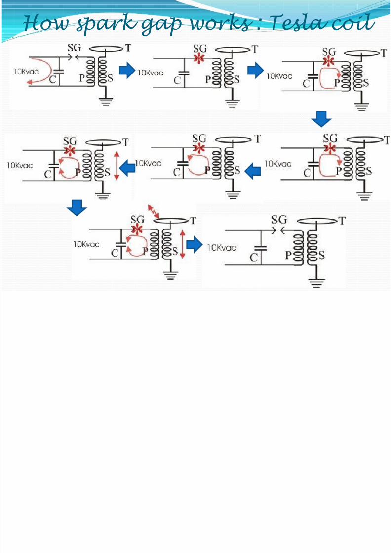
How spark gap works : Tesla coil
7/30/2019 Presentation Pulse
http://slidepdf.com/reader/full/presentation-pulse 8/27

7/30/2019 Presentation Pulse
http://slidepdf.com/reader/full/presentation-pulse 9/27
7/30/2019 Presentation Pulse
http://slidepdf.com/reader/full/presentation-pulse 10/27
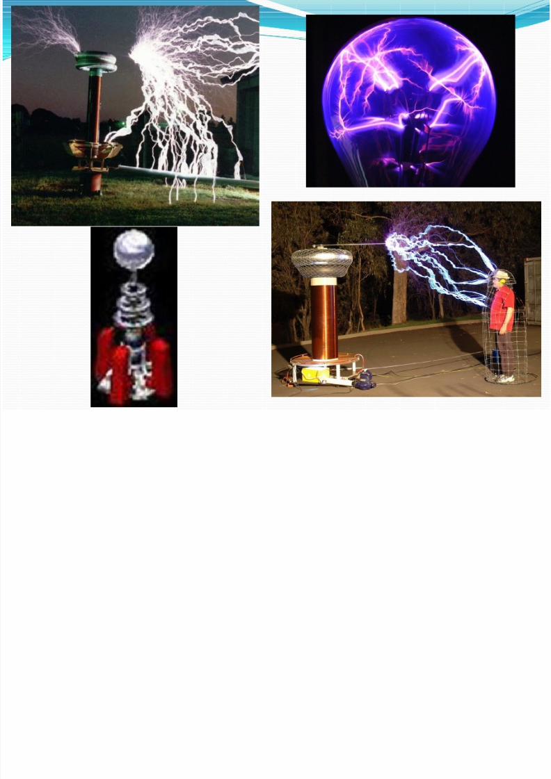
Applications
Ignition devices
Radio transmitters
Spark gaps as protective devices Sphere gap for voltage measurement
Power-switching devices
Visual entertainment

7/30/2019 Presentation Pulse
http://slidepdf.com/reader/full/presentation-pulse 11/27
THYRATRONS
7/30/2019 Presentation Pulse
http://slidepdf.com/reader/full/presentation-pulse 12/27
Introduction
What is thyratrons?
A gas filled tube used as a switch for high
electrical energy and controlled rectifier.Typically – ‘controlled gas rectifier’
What type of gas were filled in?
Mercury vapor, xenon, neon andhydrogen
7/30/2019 Presentation Pulse
http://slidepdf.com/reader/full/presentation-pulse 13/27
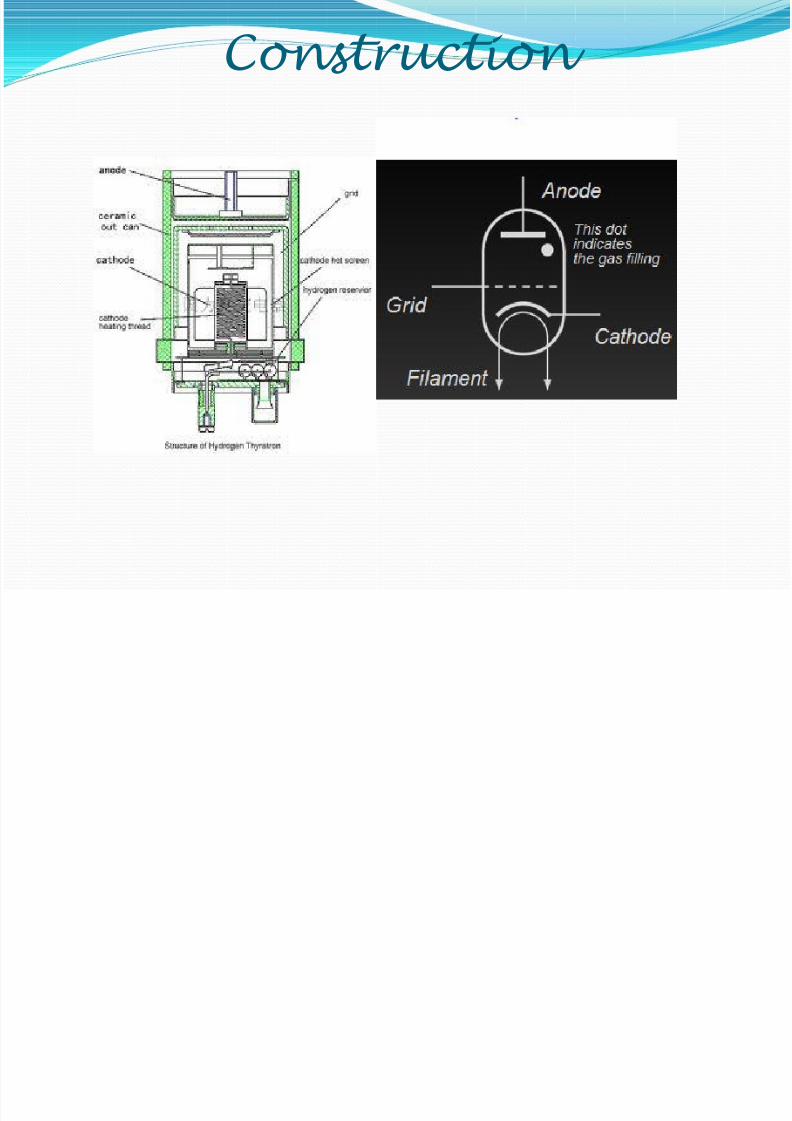
Construction
7/30/2019 Presentation Pulse
http://slidepdf.com/reader/full/presentation-pulse 14/27
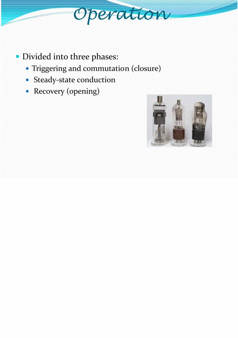
Operation
Divided into three phases:
Triggering and commutation (closure)
Steady-state conduction Recovery (opening)
7/30/2019 Presentation Pulse
http://slidepdf.com/reader/full/presentation-pulse 15/27
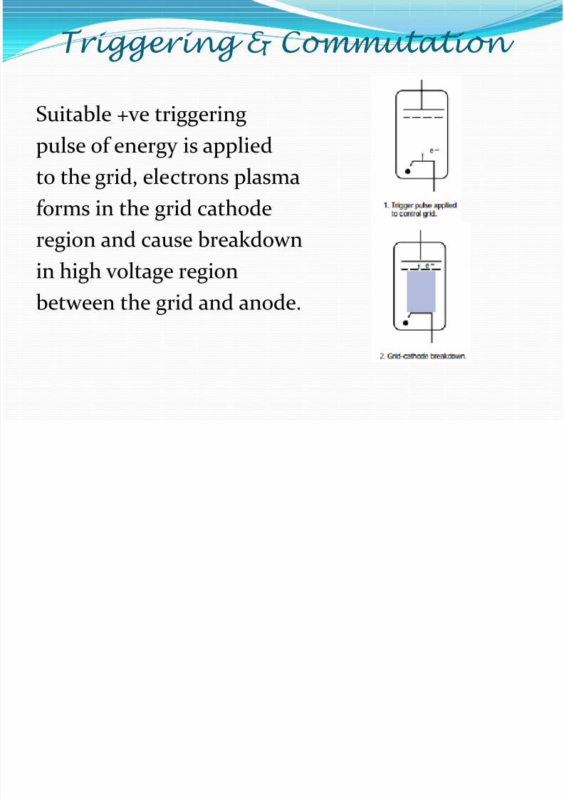
Triggering & Commutation
Suitable +ve triggering
pulse of energy is applied
to the grid, electrons plasma
forms in the grid cathode
region and cause breakdown
in high voltage region
between the grid and anode.
7/30/2019 Presentation Pulse
http://slidepdf.com/reader/full/presentation-pulse 16/27
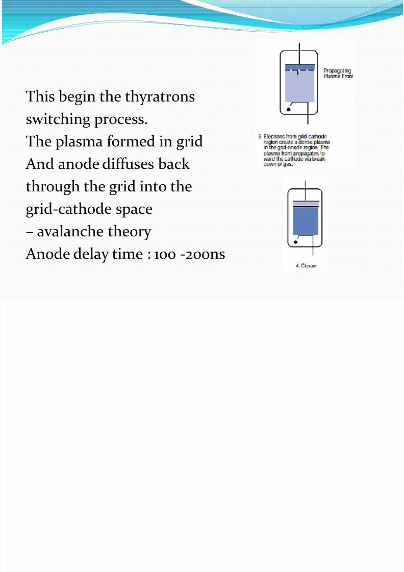
This begin the thyratrons
switching process.
The plasma formed in grid And anode diffuses back
through the grid into the
grid-cathode space– avalanche theory
Anode delay time : 100 -200ns

7/30/2019 Presentation Pulse
http://slidepdf.com/reader/full/presentation-pulse 17/27
Steady State Condition
A typical hydrogen thyratron will conduct with nearly constant voltage drop on the order of 100V regardlessof the current through the tube

7/30/2019 Presentation Pulse
http://slidepdf.com/reader/full/presentation-pulse 18/27
Recovery (Opening)
The gap ‘reopen’ via the ion diffusion to the tube inner walls and electrode surface.
Ion will recombine with electrons. Time taken : 30-150µs
Factors affecting time :
Tube type, gas filled, fill pressure
7/30/2019 Presentation Pulse
http://slidepdf.com/reader/full/presentation-pulse 19/27
7/30/2019 Presentation Pulse
http://slidepdf.com/reader/full/presentation-pulse 20/27
Variations Old technology:
Krytron
Sprytron Ignitron
Modern technology
Thyristor Triac

7/30/2019 Presentation Pulse
http://slidepdf.com/reader/full/presentation-pulse 21/27
IGNITRON
7/30/2019 Presentation Pulse
http://slidepdf.com/reader/full/presentation-pulse 22/27
Ignitrons Ignitrons are ignitor-fired mercury pool rectifiers with
very high peak and average current handling capability. electron tube functioning as a rectifier to convert
alternating current (AC) to direct current (DC)
a mercury arc rectifier controlled by a subsidiar electrode,the igniter, partially immersed in a mercury cathode.
A current passed between igniter and cathode forms a hotspot sufficient to strike an arc between cathode and anode
used in a wide variety of pulse powerapplications, such as capacitor discharge,
laser switching, magneforming,magnetizing and crowbar circuits.
They are used in switching service forcurrents ranging to 700,000 Amps with
voltages ranging to 50 kV.
7/30/2019 Presentation Pulse
http://slidepdf.com/reader/full/presentation-pulse 23/27
Triggering ignitron
There are two main ways by which the triggercan be biased:
Anode excitation: common in resistance welding applications here the anode bias is
connected to the ignitor by means of a switch(thyristor, thyratron etc.) and a resistor/fusenetwork. The ignitor current drops rapidly onignition as the anode-cathode voltage drops very low during conduction.
Separate excitation: as the name suggests, herethe ignitor circuit is largely independent of themain circuit.
Op ti
7/30/2019 Presentation Pulse
http://slidepdf.com/reader/full/presentation-pulse 24/27
Operation
(1) Anode, (2) Cathode, (3) Ignitor, (4)Mercury, (5) Ceramic insulators, (6)Cooling fluid
• A large steel container with a pool of mercury in the bottom thatacts as a cathode during operation
•
A large graphite or refractory metal cylinder, held above the poolby an insulated electrical connection, serves as the anode
• An igniting electrode (called the "ignitor"), made of a refractory semiconductor material such as silicon carbide,is briefly pulsed
with a high current to create a puff of electrically conductive
mercury plasma .• The plasma rapidly bridges the space between the
mercury pool and the anode, permitting heavy conduction between the main electrodes.
• At the surface of the mercury, heating by the resulting
arc liberates large numbers of electrons which help tomaintain the mercury arc.
• The mercury surface thus serves as the cathode,and current is normally only in one direction. Onceignited, and ignitron will continue to pa ss current until
either the current is externally interrupted or the voltageapplied between cathode and anode is reversed.
7/30/2019 Presentation Pulse
http://slidepdf.com/reader/full/presentation-pulse 25/27
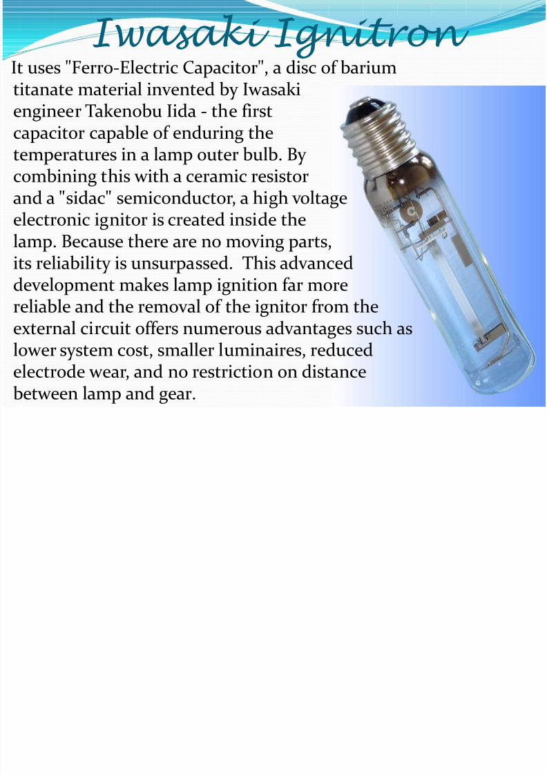
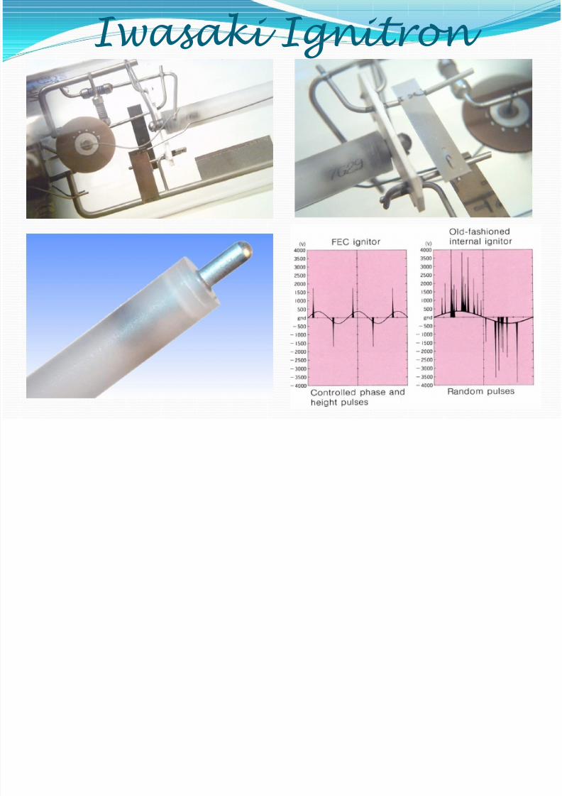
Iwasaki Ignitron It uses "Ferro-Electric Capacitor", a disc of barium
titanate material invented by Iwasakiengineer Takenobu Iida - the firstcapacitor capable of enduring thetemperatures in a lamp outer bulb. By combining this with a ceramic resistor
and a "sidac" semiconductor, a high voltageelectronic ignitor is created inside thelamp. Because there are no moving parts,its reliability is unsurpassed. This advanced
development makes lamp ignition far morereliable and the removal of the ignitor from theexternal circuit offers numerous advantages such aslower system cost, smaller luminaires, reducedelectrode wear, and no restriction on distancebetween lamp and gear.
7/30/2019 Presentation Pulse
http://slidepdf.com/reader/full/presentation-pulse 26/27
Iwasaki Ignitron

7/30/2019 Presentation Pulse
http://slidepdf.com/reader/full/presentation-pulse 27/27
THANK YOU