Embed Size (px)
Citation preview

Production Processes and Systems, Volume 5. No. 1. (2012) pp. 79-90.
PRESENT STATE AND FUTURE OF ADVANCED HIGH STRENGTH STEELS
1András Balogh, 2Imre Török, 3Marcell Gáspár, 4Dániel Juhász
[email protected], [email protected], [email protected], [email protected]
University of Miskolc, Department of Materials Processing Technologies
Abstract
Ferrous alloys are still the most widely used metallic materials. Basic design goal for engi-neers is to decrease the size and weight of structure, which can be achieved by steels using various strength increasing methods. However, the method applied for strength increasing has a significant effect on the latter production, especially welding challenges. In order to preserve the unique strength and toughness properties after welding, precisely controlled linear energy, limited interpass temperature and the conscious selection of filler metal is needed by considering the deep investigation of the so-called matching question.
Key words: high strength steel, weldability, matching, structural stability
1. Introduction
On the basis of the world-wide use, steel can be regarded as the most important metallic materials among the ferrous, aluminium, copper, nickel, titanium and zirconium alloys. The favourable ratio of the producing cost to the complex characteristics makes steel to be the leading metallic alloy.
Steels with not more than 360 MPa yield limit have met the industrial demands for a long time. Due to the strong trade competition the development of metallurgical technolo-gies was confined to purity steel and other quality viewpoints such as reproducibility, inclu-sions, gas concentration etc. Some forty years ago, the oil crisis in Middle East increased the importance of dead load of all transporting vehicles and other moving machines.
For decreasing of dead load of moving structures light metallic alloys, such as Al-Mg alloy and new kind of non-metallic materials (polymers with particular characteristics, fibre reinforced composites) had to be applied, and the strength of load carrying elements had to be increased. Using alloying elements for strengthening of steels was not passable because of the shortage and high price of alloying elements. That is why they tried firstly by low amount of alloying then the less expensive microalloying with Al, Zr, Ti, Nb, V, B.
Following these period in case of structural steels the technological strength increase got to the focal point of developing activities which became the principal trend of steel making in the last decades of the 20th and in the first ones of the 21st centuries.
2. Strengthening mechanisms of steels applied in welded structures
In developing work of steels intended to make welded structure only such strengthening mechanisms can be taken into account which do not worsen significantly the basic welda-bility characteristics of steels .

András Balogh, Imre Török, Marcell Gáspár, Dániel Juhász
80
2.1. Strain hardening
According to the conservative theory, now the cold forming can be regarded as the least suitable strengthening mechanism for steels of welded structures. Judgement of the cold forming processes is negative, since these processes mostly decrease the residual plasticity of steels which intensifies the cracking risk mainly in case of high strength steels.
In spite of this applying new metallurgical technologies different steel grades have been successfully developed in 0,5 to 3 mm thickness interval (mainly to meet the requirements of automobile industry), which can be reliably and profitably welded by both arc and re-sistance welding. Typical examples of this steel group are the cold rolled advanced high strength steel sheets denoted by S780 to S1470 developed in Japan for motor-car manufac-turing [1] and steel of SSAB in Sweden marked as Docol belonging to dual phase and mar-tensitic groups [2].
2.2. Alloying
To alloy steels for purpose of manufacturing weldments chemical elements can be only taken into account which do not move the transformation diagrams (TTT and CCT) to the right and down, consequently do not increase notably the hardening effect. On the basis of this principle it is evident that Cr, V and W elements widely used for steels of high loaded machine parts for Q+T steel making are not favourable for steels of welded structures. The possible Ni, Mo and Cu alloying elements seem to be proper compromise, but for mass steel making they are not economic [3].
2.3. Grain refinement
Since middle of the last century it has been known from scientific achievement of Hall and Petch that the grain refinement not only improves the toughness and ductility, but increases the strength as well [4].
e eR Rpc sc
k
d (1)
where: Repc MPa yield limit of the polycrystalline metal, Resc MPa yield limit of the singlecrystalline metal,
k MPa mm material constant, d mm grain size.
According to the classification system of the CR ISO 15608 standard, normalised or normalising rolled steels belong to the 1.3 subgroup. In the standardised designation system of the steels of 420 and 460 MPa yield limit the normalised condition is denoted by a capi-tal ‘N’ letter (for example: S460N). In order to grain refinement, high melting point crystal nuclei are formed (EN 10025-3). The maximum 0.2°% C content together with the favour-able Mn and Si concentration and approximately 3 Mn per Si ratio provides quite fair weld-ability.
Steels with N letter in their designation have cold crack formation liability when the condition is unfavourable (brittle microstructure elements in HAZ, tensile stress perpendic-ular to the weld and presence of much diffusible hydrogen), therefore the carbon equivalent

Present State and Prospective Developing Directions of AHSS
81
(CEV) is limited in the function of wall thickness: e.g. for S460N steel grade with 100 to 250 mm thickness CEV should be no more than 0,55 %.
In Hungary the tensile stressed wide flange of the main girder of Oszlár bridge of M3 motorway over Tisza river was designed from S360N steel with 100 mm thickness and 1200 mm width and their welding by submerged arc welding (121) was successful [5].
Normalised steel (N signed) can only be limitedly applied in heavy operation condi-tions, because their elongation measured by proportional short specimen is guaranteed up to 17 to 19 % (in the function of the thickness) and their guaranteed Charpy energy at -20 °C only 27 J, at -50 °C as low as 16 J.
2.4. Thermo-mechanical treatment
Steels of this category belong to the 2nd group in CR ISO 15608 system. In their designation an M letter means the thermo-mechanical treatment (usually rolling), for example S460M. Standard EN 10025-4 has two classes with 420 and 460 MPa yield strength. Thermo-mechanical steels contain alloying elements retarding recrystallization generally manufac-tured by controlled temperature rolling and cooled by accelerated technology.
Due to the low temperature hot forming and the partially repressed recrystallization process steel contains two or three orders of magnitude more crystal defects than the usual, which state favourably affects the strength parameters. In spite of the non-equilibrium con-dition caused by the lower than normal rolling temperature interval, due to the upper carbon content limited by 0,16 % the thermo-mechanical steels have excellent Charpy impact values, that is why thicker and thicker wall thickness has been designed in bridge manufac-turing [6]. In Hungary steel grade of S460ML was firstly applied in high quantity in the Danube bridge named Pentele located near to the town Dunaújváros [5].
Cold cracking sensitivity of thermo-mechanical steels cannot be taken into considera-tion when welding technology is planned, but in accordance with observations this suscep-tibility is less than the same of normalised steels.
The principal problem of the M steels that due to the effect of durable heat input (e.g. thermal cutting, hot forming, post heat treating) the non-equilibrium state changes into direction of equilibrium and the original condition can not be set back by neither heat treat-ing nor other available processes.
2.5. Heat treating
With normalising and thermo-mechanical treatment only the low category high strength steels can be manufactured with maximum yield limit of 560 MPa. Contrary to this with alloying of suitable chosen chemical elements (Cr, Mo, Ni, V) supporting quenching and improve so called through hardening of large diameters (mass effect) the steel can be made suitable for quenching. The steel denoted after quenching by Q letter can achieve the extra high strength steel (EHSS) and ultra high strength steel (UHSS) categories between 560 and 1400 MPa yield limit [7].
Water quenched (Q) and high temperature tempered (T) steels belong to the 3rd group of the classification system of the standard CR ISO 15608. In designation of these steels of yield limit ranges from 460 to 960 MPa the Q+T condition is denoted by capital Q letter (for instance S960Q).

András Balogh, Imre Török, Marcell Gáspár, Dániel Juhász
82
Due to the limited carbon content (Cmax=0,22 %) the steel group is considered low car-bon steel, therefore during quenching soft martensite forms, in other word ‘blind quenched condition’ comes into being, which is stabilised the consequent high temperature tempering [8].
Because of the mass problem (so called transquenching) of the heat treating the wall thickness of the quenched and tempered AHSS steel is limited by app. 150 mm.
Welding of these steels is difficult, because their brittleness is increasing with strength: the elongation of the 960 MPa strength class is only 10 %, and the low temperature applica-tion requires special manufacturing technology (denoted by L and L1 signs). Due to the special microstructure welding can be carried out only with controlled linear energy. Simi-larly to the thermo-mechanical steels the unfavourable microstructure formed in conse-quence of previous heat input can not be restored after welding [9].
3. Welding difficulties of the high strength and advanced high strength steels
Comparing the welding of advanced high strength steels to the mass structural steels of not higher than 360 MPa yield limit a few novelties and difficulties occur. Paying primary attention to the thermo-mechanically rolled as well as the quenched and tempered AHSS, the weldability problems can be summarised in the following chapters.
3.1. Brittleness
The highest problem of the HSS and AHSS steels as well as all newly developed steels is that decreasing ductility is associated to increasing strength [10].
Ultimate Tensile Strength, Rm in MPa
20 000 40 000 Rmx A = 60 000
Elo
ng
atio
n, A
in %
Figure 1. Relationship between ultimate tensile strength and specific elongation for tradi-tional structural steels and advanced high strength steels (AHSS)

Present State and Prospective Developing Directions of AHSS
83
The ratio of flow stress to tensile strength goes to one which means increased brittle-ness. Figure 1. shows that during development of EHSS and UHSS steel considerable atten-tion was paid for this negative phenomenon and in case of EHSS the product of the ultimate tensile strength and the specific elongation was doubled, in case of UHSS was tripled [11], [12].
This developing conception points out very advantageous direction and among others it makes possible to moderate the quite heavy weldability problems [13]. The most conspicu-ous phenomenon of the brittleness is the decrease of Charpy impact energy in the weld and first of all in the critical strips of the heat affected zone. Impact energy dynamically de-creases at negative temperature; therefore limitation of wall thickness should be prescribed for the welded structures operating in the open air. Bracing exceptions could be the thermo-mechanical rolled plates, where some of manufacturers could achieve excellent Charpy impact energies even in thick sections.
In case of advanced high strength steel largeness of impact energy and its dependence in different circumstances differs from normal structural steels hence (predicting the wide spread of advanced high strength steels) the designers’ and welding engineers’ practice should radically be changed in the future [14].
One of the first signs of the aforementioned prognosis, that some of the greater universi-ties and research institutes have launched common projects in order to extend Eurocode 3 (unified European designer directives for welded structures made of steels and loaded by dynamic forces) to EHSS and UHSS categories [15], [16], [17], [18], [19], [20]. The pre-sent state can maintain further with difficulty, because Eurocode 3 calculates maximum 160 MPa stress range for all strength categories, which can be considered the highest fa-tigue limit of the unalloyed structural steel of 240 MPa yield limit (37 kp/mm2 guaranteed ultimate tensile strength).
3.2. Crack formation in weld and transition zone
Crack means the elemental danger for welding engineers. Together with the endeavours of manufacturers of base and filler materials crack prevention should be emphasised when the welding technology is elaborated and executed. For the same reason degree and severity of non-destructive testing (NDT) need to be increased.
3.2.1. Crystallisation(hot)crackingThe well-known manufacturers of high strength steels pay special attention to steel pro-cessing (slag inclusions, gas impurities, decrease of solid impurities (S and P) forming eutectic with low melting point, homogenisation, controlled rolling and/or heat treating), therefore the risk of crystallisation crack formation almost does not threat in the low inter-val of heat input limited by other reasons.
However increased attention should be paid to thick plates (s>50 mm), where metallur-gical technologies can not produce the same composition and mechanical properties in the middle third part of plate thickness compared to the other surface parts [14].
3.2.2. ColdcrackingIt is widely accepted that the cold crack sensitivity of high strength steels essentially de-pends on three main factors [17]:
microstucture and its hardness,

András Balogh, Imre Török, Marcell Gáspár, Dániel Juhász
84
the diffusible hydrogen content in the weld and the fusion strip next to the weld in HAZ,
existence of tensile strength needed to crack propagation. Simplifying the crack susceptibility concerned the microstructure is generally expressed
by the quenching susceptibility. The carbon equivalent, combining the effect of carbon content and the alloying elements (moving significantly right the transformation diagrams) to the hardening potential, determines the quenching (more exactly hardening) susceptibil-ity. On the basis of carbon content and carbon equivalent the Graville diagram divides steels into three groups (Figure Figure 2. ). Steels falling into the area I can be welded without any problems and special precautions. Steels belonging to area II can be welded using from below limited heat input, while the welding of steels of area III can be carried out by controlled heat input with simultaneous preheating [7].
CE=C+(Mn+Si)/6+(Cr+Mo+V)/5+(Ni+Cu)/15
Area I
Carbon Equivalent, %
Car
bon
Con
tent
, %
Area II Area III
0.3 0.5 0.7 0.9 1.10.2 0.4 0.6 0.8 1.2
0.1
0.3
0.5
0.0
0.2
0.4
0.6
1.0 1.41.3
S355J2 S460NS460MS960Q
Figure 2. Effect of carbon content and carbon equivalent to crack sensitivity in the Graville diagram (Symbols of each steel category mark the maximum content given by the product
standard)
Various formulae were elaborated for the computation of carbon equivalent characteris-ing the different steel grades. Advantage of the formula belonging to Graville diagram is that it takes the Si content into consideration as well:
6 5 15
Mn Si Cr Mo V Ni CuCE C
(2)
Neglecting the Si content the EN 10025 euro standard uses the following carbon equiva-
lent calculating equation:
6 5 15
Mn Cr Mo V Ni CuCEV C
(3)
Present State and Prospective Developing Directions of AHSS
85
On the basis of the Graville diagram preheating and from below limited linear heat in-
put is needed for the welding of high strength steels. The increased linear heat input has a negative effect at the same time, since the microstructure, produced by novel metallurgical processes, suffers failure during welding and other thermal operations (thermal cutting, stress relieving, hot straightening). Failures can worsen the operating characteristics of welded joints (mainly toughness and strength), and according to our present knowledge there are neither laboratory nor industrial processes for the restoration of the original condi-tion.
At the end of the last century it became known that the diffusible (atomic) hydrogen is at least as responsible for the initiation of cold cracks as the formation of hard, brittle phas-es. During welding of EHSS and UHSS steels, for the effective elimination of hydrogen sources, well dried consumables giving basic slag are necessary to use in order to keep the hydrogen content below the safe 5 ml/100 g limit in weld and mainly in the high tempera-ture areas of heat affected zones. The out off the weld diffusion of hydrogen atoms, got into the welded joint before and during welding should be supported by a 100 to 150 °C heat treatment.
For the formation of cold cracking mostly the tensile strengths perpendicular to the weld are responsible. Avoidance of thicker plates and the rigid structure restraining the defor-mation is an emphasized challenge of the designers. If the realisation of previous designer’s goals are not possible, the preheating temperature should be increased, which – according to the aforementioned phenomena – can cause harmful consequences.
3.3. Matching problem
Matching does not have an adequate Hungarian term yet means the very close sized proper-ties between the base metal and the weld, first of in case of yield limit and other strength parameters.
Regarding low strength structural steels the overmatching of strength properties is typi-cal, namely the weld has higher strength with almost one strength category (60 MPa).
In contrast to mild steel for the high strength category advantages can be expected from undermatching: elimination of cold cracks and lamellar tearing. When deciding the degree of matching, ductility properties should also be investigated besides the strength. In case of welding of EHSS and UHSS steels it is practical to choose filler metal of one or two strength category lower and elongation of four…five percents higher. This type of strength undermatching and simultaneous elongation overmatching can be fulfilled by special alloy-ing different or significantly different from the alloy type of base material (it is advanta-geous adding Ni and Mo elements into filler material).
4. Practical advices for welding of high strength steels
In contrast to the traditional structural steels the modern EHSS and UHSS steels should be welded in different manner. Starting the main goal of the welding task welding engineers should be thinking about the basis of relevant theory and the available practical experienc-es. The challenge of welding engineers is a continuous progressive development of tech-nology taking the obtained observations into consideration and progressing into the direc-tion of a possible technological optimum.
András Balogh, Imre Török, Marcell Gáspár, Dániel Juhász
86
4.1. Filler material selection on undermatching principle
Presently the normal structural steels of yield strength not more than 360 MPa are welded with filler metals selected on the principle of overmatching and technology to realise over-matching. When advanced high strength steels have to be welded, this practice should be given up and it is desirable to follow the undermatching principle.
Undermatching requires filler material by 10 to 20 % less yield limit than the same of base metal. When relatively brittle base metals are welded, it is more advantageous to rely on higher plasticity and therefore more toughness with lower crack initiation risk, instead of matching of strength properties. These filler materials generally contain more alloying components compared to base material; hence they are much more expensive.
However, it is not sufficient to choose the suitable filler material. The welding technol-ogy itself with undermatched filler materials seems just as important. The technology sig-nificantly affects the quality of weld through the rate of dilution of weld with base metals as well as the morphology of dendrite microstructure and the welding techniques resulting multipass weld build up.
4.2. Controlled linear energy
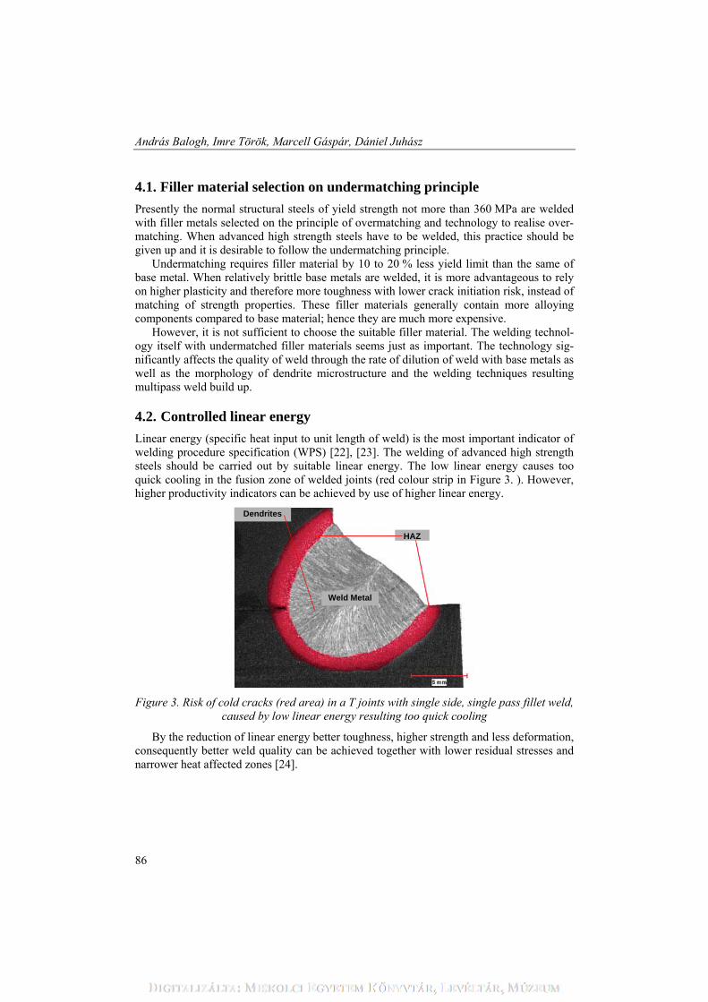
Linear energy (specific heat input to unit length of weld) is the most important indicator of welding procedure specification (WPS) [22], [23]. The welding of advanced high strength steels should be carried out by suitable linear energy. The low linear energy causes too quick cooling in the fusion zone of welded joints (red colour strip in Figure 3. ). However, higher productivity indicators can be achieved by use of higher linear energy.
Dendrites
Weld Metal
HAZ
Figure 3. Risk of cold cracks (red area) in a T joints with single side, single pass fillet weld, caused by low linear energy resulting too quick cooling
By the reduction of linear energy better toughness, higher strength and less deformation, consequently better weld quality can be achieved together with lower residual stresses and narrower heat affected zones [24].

Present State and Prospective Developing Directions of AHSS
87
4.3. Optimal preheating and interpass temperature
In order to reduce the cold, especially hydrogen induced crack sensitivity welding should be performed by tightly controlled and kept preheat and interpass temperatures. For in-stance the suggested minimum preheating temperature, for maximum 50 mm thick plates with the yield strength of 960 MPa, is 100 to150 °C, while the maximum interpass tempera-ture is limited by 300 °C [24].
The preheating temperature together with the linear energy determines the critical cool-ing time. According to the practical experiences in case of a given steel grade, the cooling time from A3 temperature to the temperature belonged to the so called ‘nose point’ of con-tinuous cooling transformation diagram (approximation by cooling time from 850 °C to 500 °C marked with t850/500 or shortly t8,5/5) determines the final microstructure, and main-taining it in a given interval the possible quench hardening and/or the decrease in toughness can be well controlled.
In one of the plants of Finnish RUUKKI Corporation, located in Jászberény (Hungary) such a technology were elaborated which keeps t8,5/5 cooling time between 6 and 10 s [14]. The demanded cooling time is measured by NiCr-Ni thermoelement submerged into weld pool and during crystallisation it was solidified into the weld (Figure 4. ).
Well dried filler materials with low hydrogen content (basic coated electrodes, basic flux and high purity shielding gas) should be chosen together with the careful preparation of the work piece surface to decrease the potential hydrogen sources.
WeldWorkpiece
Thermo-elements
Ceramic guide withdouble holes
Figure 4. The instrument for the measuring the t8,5/5 cooling time and the sketch of measurement
4.4. Non-continuous heat input
From previous chapters it can be clearly seen that the welding of AHSS can be successful only with use of well defined linear energy. The fine and reproducible alteration of heat

András Balogh, Imre Török, Marcell Gáspár, Dániel Juhász
88
input can be only achieved by modern welding machines [25]. In this field we see great possibility in on-line programmable welding equipments, which can provide controlled welding process with the same set of parameters.
The ‘fine tuning’ of linear energy can better be solved by pulsed energy welding equipment than by traditional power sources providing only continuous energy input [26].
The pulsed energy welding is principally possible and desirable for sheets, root passes and other than flat positions. In case of mechanised and robotised welding applications, pulsed energy input can be well applied as well, because this technique improves the arc stability and weld quality, with this technique the metal transfer can comfortable be con-trolled [27].
5. Summary
Analysing chemical composition, manufacturing processes and welding behaviour of ad-vanced high strength steels (AHSS), among them the extra high strength steels (EHSS) and ultra high strength steels (UHSS) the following statements can be pointed out. 1. Non-equilibrium structure of the advanced high strength steels straightened by strain
hardening, transformation hardening and controlled temperature hot forming is unfa-vourable for welding. Heat energy input during preparing, carrying out and after weld-ing causes disadvantageous changes in microstructure, which later can not economical-ly be restored in workshop conditions.
2. According to the Graville diagram, in which the advanced high strength steels are located in area iii, welding of the AHSS category steels should primarily be planned depending on the manufacturing process, yield limit, wall thickness and expected load with controlled (usually both upper and lower sides) linear energy and preheating. For inspection of executing process of welding operation the t8,5/5 expected cooling time in-terval is necessary to prescribe and during welding it should be checked using suitable measuring instrument. Since the crack sensitivity of the high strength steels is in-creased, after welding complete non-destructive tests (NDT) need to be executed for detecting the possible cracks and other crack like imperfections.
3. Welding can be carried out with all welding processes by which the low diffusible hydrogen content (5 ml/100 g metal) in the weld and the fusion zone of welded joint can be achieved. Before, during and after welding the hydrogen sources should be strongly decreased. When filler material is selected, the principle of strength under-matching should be followed. The specific elongation of the filler material should al-ways be greater than the same of base metals.
4. Knowing the present trends of the spread of advanced high strength steels turning out of new, higher strength AHSS steels can be predicted. During developing work of the new steel types the weldability viewpoints should be taken into account to a greater ex-tent. If this demand is not increasingly fulfilled the new steels need to be joined other than welding processes (e.g. clinching, riveting, adhesive bonding [28] and similar ones).

Present State and Prospective Developing Directions of AHSS
89
6. Acknowledgement
This research was carried out as part of the TAMOP-4.2.1.B-10/2/KONV-2010-0001 pro-ject supported by the European Union, co-financed by the European Social Fund. Authors would like to say special thanks for the financial sponsorship.
7. References
[1] Mega, T.; Hasegawa, K.; Kawabe, H.: Ultra High-Strength Steel Sheets for Bod-ies, Reinforcement Parts, and Seat Frame Parts of Automobile, JFE Technical Re-port, 2004. No 4 (November).
[2] DOCOL High Strength Steels for the Automotive Industry www.ssab.com [3] Balogh A.; Schäffer J.; Sárvári J.; Tisza M.: Mechanikai Technológiák, Miskolci
Egyetemi Kiadó, 2003. [4] Tisza M.: Introduction to Materials Sciences, University Publisher, Miskolc, 2000 [5] Domanovszky S.: A hegesztett hidak építésének 80 éve Magyarországon, 25. Jubi-
leumi Hegesztési Konferencia, Budapest, 2010. május 19-21. [6] Hever, M.; Schröter, F.: Modern Steel - High Performance Material for High Per-
formance Bridges, 5th International Symposium on Steel Bridges, Barcelona, 2003, p.:80-91.
[7] ASM International Handbook Committee, Volume 6, Welding, Brazing, and Sol-dering 10th Edition, 1995.
[8] Szunyogh L.: Hegesztés és rokon technológiák Kézikönyv, Gépipari Tudományos Egyesület, Budapest, 2007.
[9] Balogh A.: Ömlesztőhegesztő eljárások, IWE oktatási segédlet, Miskolci Egyetem Továbbképzési Központ, 2001
[10] Tisza M.: Material and Technological Innovations in Sheet Metal Forming, 17th International Conference on Mechanical Engineering, Gyergyószentmiklós (Ro-mania), 23-26. April 2009.
[11] Tisza M.: Material and Technological Innovations in Sheet Metal Forming, Deb-receni Egyetem, Műszaki Füzetek, 2010. ISBN 978-963-7064-24-1, pp. 9-16.
[12] Chung, J.; Kwon, O.: Development of high performance auto steels at Posco steels, Proc. of the 9th ICTP Conference, Gjeongjyu-Korea, 7-11. September 2008. p.: 3-8.
[13] Juhász D.: Nagyszilárdságú acélok ellenállás-ponthegesztése, Hegesztő szakmér-nöki diplomaterv (tervezésvezető: Balogh A.) Miskolci Egyetem, 2011.
[14] Gáspár M.: Nagyszilárdságú, nemesített állapotú szerkezeti acélok hegesztése, MSc diplomaterv (tervezésvezető: Balogh A.) Miskolci Egyetem, 2011.
[15] Johansson, B.; Collin, P.: Eurocode for high strength steel and applications in construction, Lulea University of Technology, Sweden, 2008.
[16] Bursi, O. S.; Kumar, A. et al.: Design and integrity assessment of high strength tubular structures for extreme loading conditions, Research programme of the re-search fund for coal and steel, 2009.
[17] Érsek L.: A hegesztett nagyszilárdságú acélok fáradási szilárdságának növelése utólagos kezelési eljárások alkalmazásával, Hegesztéstechnika, Vol XVII (2006), No 3, p.13-17.

András Balogh, Imre Török, Marcell Gáspár, Dániel Juhász
90
[18] Pijpers, R.M.; Kolstein, M.H.; Romeijn, A; Bijlaard, F.S.K: Fatigue experiments on very high strength steel base material and transverse butt welds, Advanced Steel Construction, Vol. 5, 2007.
[19] Hobbacher, A.: The new IIW recommendations for fatigue assessment of welded joints and components; A comprehensive code recently updated, 2007.
[20] Gerster, P.: MAG-Schweissen hochfester Feinkornstähle im Fahrzeugkranbau, Vortrag-Grossen Schweisstechnischen Tagung 2000 in Nürnberg.
[21] American Welding Society Welding Handbook. 9th Edition, Volume 2: Welding processes, Part 1, Miami, FL: AWS, 2004.
[22] Balogh A.: A vonalenergia számítása és szerepeltetése a WPS-ben, Hegesztéstechnika, Vol XI (2000), No 1, p.: 3-7.
[23] Balogh A.: A bevontelektródás kézi ívhegesztés vonalenergiája, Gép. LII. (2001). No. 12. p.: 9-14.
[24] Welding HARDOX and WELDOX, TechSupport #25, www.ssab.com [25] Killing, R.: Welding Processes and Thermal Cutting. English Edition, Volume 1
DVS-Verlag GmbH, Düsseldorf, 2001. [26] Balogh A.: Szakaszos energiabevitel ömlesztő- és sajtolóhegesztéseknél,
Hegesztéstechnika, XX, (2009), 1. szám, p.: 7-12. [27] Balogh A.: Szakaszos energiabevitelű ömlesztőhegesztések jelenlegi helyzete és
várható fejlődési irányai, TÁMOP-4.2.1.B-10/2/KONV-2010-0001 jelű projekt, 2011. augusztus.
[28] WorldAutoSteel.: Advanced High Strength Steel (AHSS) Application Guidelines. Version 4.1. June 2009 www.wordautosteel.org.