Embed Size (px)
Citation preview
Guest Reviewers
Ivan DUDURYCH
Tahir LAZIMOV
Murari M. SAHA
Editorial Board
Piotr PIERZ – art manager
Miros aw UKOWICZ, Jan I YKOWSKI, Eugeniusz ROSO OWSKI,
Janusz SZAFRAN, Waldemar REBIZANT, Daniel BEJMERT
Cover design
Piotr PIERZ
Printed in the camera ready form
Institute of Electrical Power Engineering
Wroc aw University of Technology
Wybrze e Wyspia skiego 27, 50-370 Wroc aw, Poland
phone: +48 71 320 26 55, fax: +48 71 320 26 56
www: http://www.ie.pwr.wroc.pl/; e-mail: [email protected]
All right reserved. No part of this book may be reproduced by any means,
electronic, photocopying or otherwise, without the prior permission
in writing of the Publisher.
© Copyright by Oficyna Wydawnicza Politechniki Wroc awskiej, Wroc aw 2013
OFICYNA WYDAWNICZA POLITECHNIKI WROC AWSKIEJ
Wybrze e Wyspia skiego 27, 50-370 Wroc aw
http://www.oficyna.pwr.wroc.pl
e-mail: [email protected]
ISSN 2084-2201
Drukarnia Oficyny Wydawniczej Politechniki Wroc awskiej. Order No. 295/2013.
Dynamic Thermal Line Rating,
distance protection,
power swing, third zone
ukasz STASZEWSKI*, Waldemar REBIZANT*
THERMAL CALCULATION
FOR DISTANCE PROTECTION ENHANCEMENT
Worldwide analysis of recent wide area cascading failures has shown that very often their main
cause was the mal-operation of the distance protection relay third zone. The load encroachment and
power swing phenomena are the two dire problems to solve when dealing with the third zone of dis-
tance protection. The vast number of blackouts could have been avoided or the consequences lowered
if the distance relay had not operated due to impedance encroachment while there was no risk of fur-
ther, continuous operation.
This paper proposes a way to improve operation of the distance protection relay by introducing
a new blocking algorithm that uses the Dynamic Thermal Line Rating (DTLR) to restrain relay from
tripping when conditions in electrical power system allow for it.
1. DISTANCE PROTECTION RELAY
A high speed protection for transmission and distribution circuits is under continu-
ous development. It considers the most important fact for protection devices that is to
meet the requirements of combining fast fault clearance with selective tripping. Thus
for many years distance protection relay has been one of the most commonly used
devices amongst electrical protection equipment. Distance protection is comparatively
simple to apply and can be fast in operation for faults located along the majority of
protected circuit. It can also provide both primary and remote back-up functions in
a single device [1].
The basic principle of operation of the distance protection relay is based on imped-
ance calculation seen by the relay. Since the impedance of a transmission line is pro-
portional to its length, for distance measurement it is appropriate to use a relay able to
_________
* Wroc aw University of Technology, Institute of Electrical Power Engineering, Wybrze e Wyspia -
skiego 27, 50-370 Wroc aw, Poland.
. STASZEWSKI, W. REBIZANT84
measure the transmission line impedance to a predetermined point. Such a relay is
designed to operate only for faults occurring between the relay location and the se-
lected reach point, thus giving discrimination for faults that may occur in different line
sections. The ratio between voltage and current phasors measured at the relay installa-
tion point is calculated. The impedance calculations are based upon the following re-
lationship:
R
RR
I
VZ (1)
with: RZ , RV and RI being impedance, voltage and current phasors, respectively,
whereas the detailed algorithms can be found in [2, 3].
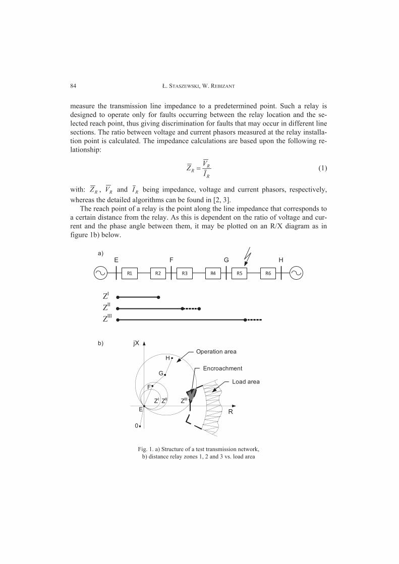
The reach point of a relay is the point along the line impedance that corresponds to
a certain distance from the relay. As this is dependent on the ratio of voltage and cur-
rent and the phase angle between them, it may be plotted on an R/X diagram as in
figure 1b) below.
b)
a)
jX
RE
F
G
H
0
ZI ZII ZIII
Operation area
Load area
Encroachment
ZI
ZII
ZIII
E
R1 R2
F
R3 R4
G
R5 R6
H
Fig. 1. a) Structure of a test transmission network,
b) distance relay zones 1, 2 and 3 vs. load area
Thermal Calculation for Distance Protection Enhancement 85
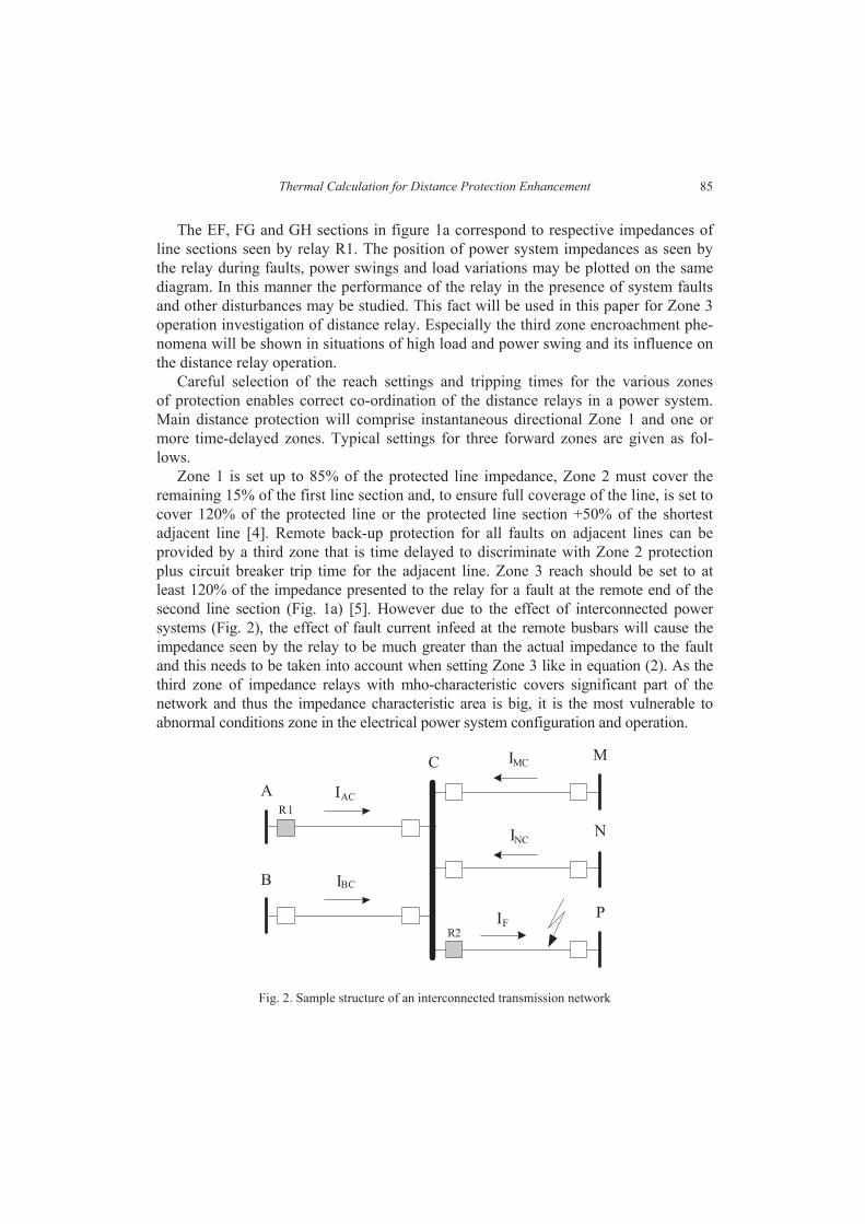
The EF, FG and GH sections in figure 1a correspond to respective impedances of
line sections seen by relay R1. The position of power system impedances as seen by
the relay during faults, power swings and load variations may be plotted on the same
diagram. In this manner the performance of the relay in the presence of system faults
and other disturbances may be studied. This fact will be used in this paper for Zone 3
operation investigation of distance relay. Especially the third zone encroachment phe-
nomena will be shown in situations of high load and power swing and its influence on
the distance relay operation.
Careful selection of the reach settings and tripping times for the various zones
of protection enables correct co-ordination of the distance relays in a power system.
Main distance protection will comprise instantaneous directional Zone 1 and one or
more time-delayed zones. Typical settings for three forward zones are given as fol-
lows.
Zone 1 is set up to 85% of the protected line impedance, Zone 2 must cover the
remaining 15% of the first line section and, to ensure full coverage of the line, is set to
cover 120% of the protected line or the protected line section +50% of the shortest
adjacent line [4]. Remote back-up protection for all faults on adjacent lines can be
provided by a third zone that is time delayed to discriminate with Zone 2 protection
plus circuit breaker trip time for the adjacent line. Zone 3 reach should be set to at
least 120% of the impedance presented to the relay for a fault at the remote end of the
second line section (Fig. 1a) [5]. However due to the effect of interconnected power
systems (Fig. 2), the effect of fault current infeed at the remote busbars will cause the
impedance seen by the relay to be much greater than the actual impedance to the fault
and this needs to be taken into account when setting Zone 3 like in equation (2). As the
third zone of impedance relays with mho-characteristic covers significant part of the
network and thus the impedance characteristic area is big, it is the most vulnerable to
abnormal conditions zone in the electrical power system configuration and operation.
M
A IAC
C
B IBC
IMC
INC
IF
N
P
R1
R2
Fig. 2. Sample structure of an interconnected transmission network
. STASZEWSKI, W. REBIZANT86
Considering the problem of backing up the protection system of line CP (relay R2,
Fig. 2) by the distance relay R1 it must be taken into account that because of the
currents contributions from the lines BC, CM and CN, the third zone setting will be
equal to:
AC
NCMCBCCPAC
III
I
IIIZZZ 12.1 (2)
where: ZIII is apparent impedance seen by the relay R1 in case of the other lines cur-
rent contribution.
In case of an extreme situation of equal contribution to the fault current from all the
remaining lines the third zone relay setting will be:
CPACIII ZZZ 8.4 (3)
Therefore the third zone is especially exposed to load encroachment and power
swing – all these situations can lead to the measured impedance encroachment into
the Zone 3 area. This results in relay mal-operation and can be a leading factor to
a large scale blackout occurrence, as it was seen, e.g. in Germany on November 4th,
2006 [5].
Despite the fact of Zone 3 setting encroachment, the system operational conditions
may not be dangerous and in case of load encroachment the load may be permissible
due to the transmission lines temporary loadability. In case of stable power swing,
after some time the system recovers to its normal operation conditions. The important
issue is to distinguish whether the third zone area encroachment is a result of fault and
the relay should operate, or it is one from above-mentioned situations and the relay
decision about tripping should be restrained.
There are various ways to avoid over-tripping due to unwanted impedance en-
croachment, both at the level of protection designing (characteristic shape shifting,
adding restrictions) and during the relay operation (measuring additional criteria
signals, e.g. zero sequence currents) [1–3]. However, it is very difficult to predict all
possible situations in power system and all possible operating conditions, thus none
of them is perfect. This paper is focused on the possibility of Dynamic Thermal
Line Rating usage to prevent distance protection relay from tripping in situations of
extreme load conditions and power swing by introducing an additional blocking
signal into the standard distance relay. The blocking signal is based on the DTLR
technique monitoring weather conditions and calculating the overhead conductor
temperature and actual for ambient weather conditions conductor current limit as
well as the time left to reach this thermal limit.
Thermal Calculation for Distance Protection Enhancement 87
2. DYNAMIC THERMAL LINE RATING BASICS
The Dynamic Thermal Line Rating technique aims at real time calculation of an
overhead bare conductor ampacity dependent on the ambient weather conditions. The
DTLR algorithm cooperates with standard distance protection devices to fully utilize
the transmission line by calculation of temporary current-carrying capability.
The conductor temperature is calculated from the heat balance equation [6, 7]:
isrc qqqq (4)
where: qc, qr are heats dissipated due to convection and radiation and qs, qi are heat
gain due to solar radiation and heating due to Joule’s law, respectively.
Each of above heat balance components are calculated in numerical way. Specific
formulas the calculations are based on can be found in [6]. However, at this point, it is
worth mentioning that the most significant factors for the heat balance are the convec-
tive cooling (due to wind) and Joule’s heating (due to current flow and conductor re-
sistance change).
Basing on the heat balance it is possible, using numerical solutions, to compute the
current conductor temperature as well as the time needed for the conductor to reach its
thermal limit according to the actual current value and ambient weather conditions.
The solution is given by the following:
])([1 2
rcsC
p
C qqqITRmCdt
dT(5)
where m is mass of conductor and Cp is specific heat of conductor material.
3.ENHANCED DISTANCE PROTECTION SCHEME
During the high load and power swing phenomena there is a high risk of the meas-
ured impedance encroachment into the Zone 3 area. Both these situations correspond
to current values higher than the values during the normal operating conditions thus
the measured impedance is sometimes even much lower than during the normal oper-
ating conditions (Eq. 1). The standard way of designing protection devices usually
does not take into consideration the Joule’s law, i.e. the fact that higher currents evoke
higher conductor temperatures and each conductor has its thermal limit that due to the
safety reasons cannot be exceeded.
The Dynamic Thermal Line Rating application introduces an additional algorithm
into a standard distance relay, that is based on real-time conductor temperature calcu-
. STASZEWSKI, W. REBIZANT88
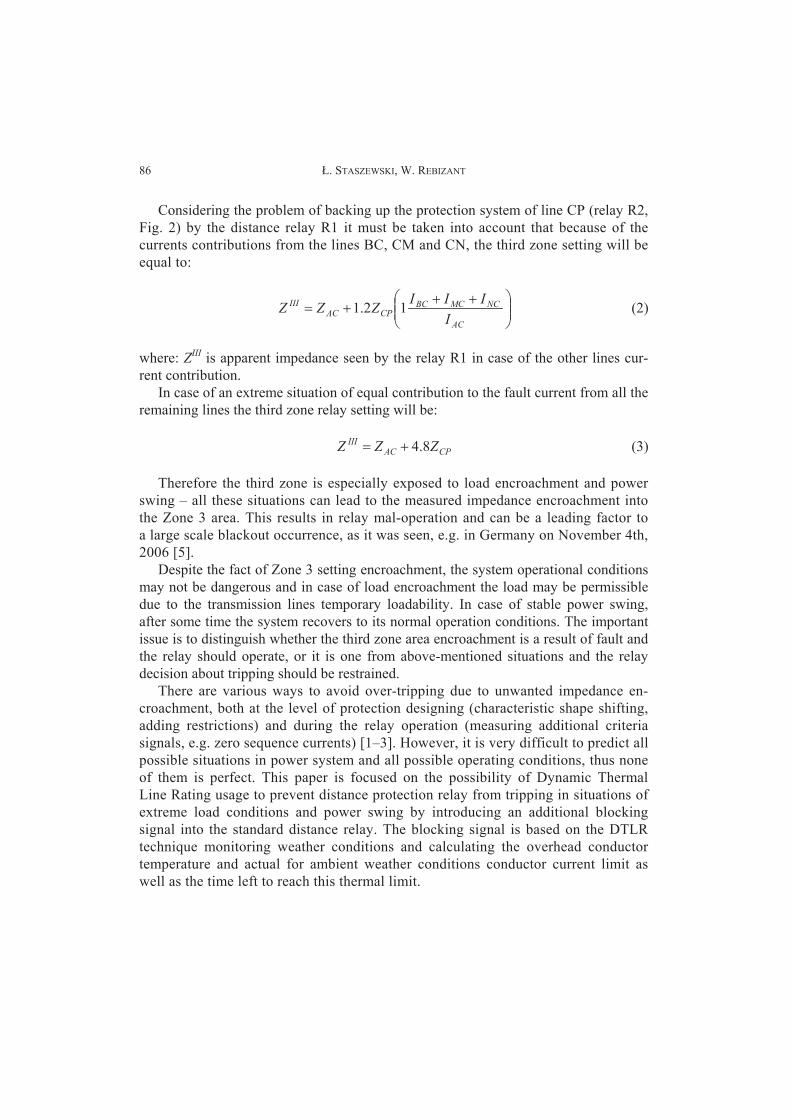
lation. The aim is to restrain the relay from tripping until the conductor temperature
reaches its thermal limit. The block scheme of DTLR supported distance relay opera-
tion is presented in figure 3 below:
Z ZIII
Z
TC TCmax
yes
TRIPPING
yes
maxC
C
dTT
dt
TRIPPING
yes
NO TRIPPINGnono
1o
2o
3o
Fig. 3. Block diagram of a distance relay with new blocking algorithms
The block diagram above presents the idea of a standard distance relay enhance-
ment based on temperature calculation. The relay acquires current samples and then
using standard Fast Fourier Transform (FFT) computes the magnitudes of phase cur-
rent signals, which is followed by computation of the conductor temperature [8].
Block 1 of the new protection scheme is a standard solution applied commonly in
impedance relays. Its task is to compare the measured (seen by the relay) impedance
with Zone 3 setting and operate if the impedance encroaches on the operation area
(Fig. 1b). However, as it was mentioned earlier, there are some possible situations
during which impedance encroachment occurs when the relay decision of tripping is
unnecessary and even highly unwanted. Therefore there is a need for introducing ad-
ditional blocks 2 and 3 to the relay logic, as described below.
Block 2, presented in figure 3, is responsible for the conductor temperature moni-
toring and ensures that it will not exceed the designed, for particular conductor,
maximum operating temperature. Thus in case of heavy load and power swing it al-
lows the transmission line to be operated safely, without tripping, when sufficient
cooling conditions are met.
Thermal Calculation for Distance Protection Enhancement 89
However as in some cases the temperature itself is not a sufficient factor to decide
an additional algorithm (Block 3) is needed. Here a ratio of a conductor temperature
change is observed. As the fault causes faster change in current magnitudes than
power swings or heavy load situations, it is reasonable to use the information about
the speed of change to determine whether the situation met is safe for further operation
or if it should be stopped.
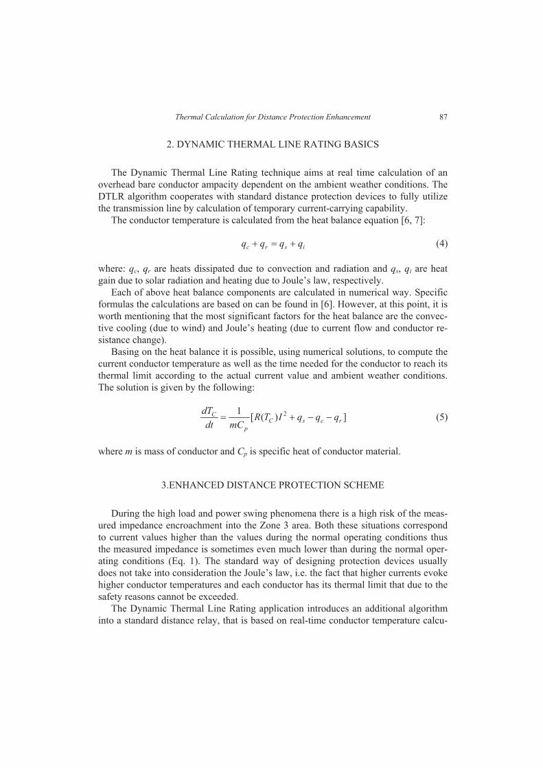
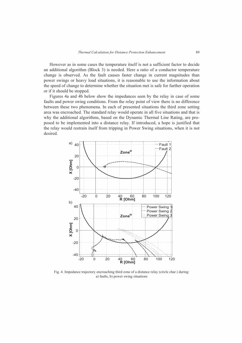
Figures 4a and 4b below show the impedances seen by the relay in case of some
faults and power swing conditions. From the relay point of view there is no difference
between these two phenomena. In each of presented situations the third zone setting
area was encroached. The standard relay would operate in all five situations and that is
why the additional algorithms, based on the Dynamic Thermal Line Rating, are pro-
posed to be implemented into a distance relay. If introduced, a hope is justified that
the relay would restrain itself from tripping in Power Swing situations, when it is not
desired.
-20 0 20 40 60 80 100 120
-40
-20
0
20
40
R [Ohm]
X [
Oh
m]
ZoneIII
Fault 1Fault 2
-20 0 20 40 60 80 100 120
-40
-20
0
20
40
R [Ohm]
X [
Oh
m]
Power Swing 1Power Swing 2Power Swing 3Zone
III
a)
b)
Fig. 4. Impedance trajectory encroaching third zone of a distance relay (circle char.) during:
a) faults, b) power swing situations
. STASZEWSKI, W. REBIZANT90
4. PROTECTION TESTING RESULTS
During the tests AFL 6 240 conductor with rated current of 645 [A] and its thermal
limit of 60 [ C] was used at nominal transmission line voltage of 110 [kV], protected
line length was 70 [km] which corresponds to 29.96 [ ]. Fault and power swing
situations were simulated and examined and the testing results will be presented be-
low. The most important signals from the point of view of introducing the new algo-
rithm were taken into account. Thus the current magnitude (as a factor highly respon-
sible for the conductor temperature), the conductor temperature (as in the Block 2) and
the ratio of change of the conductor temperature were examined (as in the Block 3).
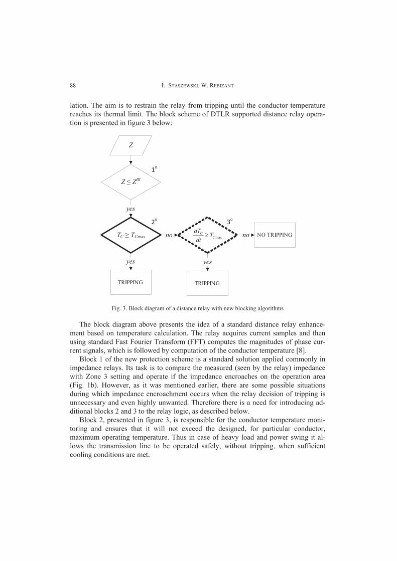
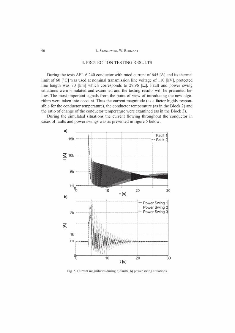
During the simulated situations the current flowing throughout the conductor in
cases of faults and power swings was as presented in figure 5 below.
0 10 20 300
1k
2k
t [s]
I [A
]
Power Swing 1
Power Swing 2
Power Swing 3
0 10 20 300
5k
10k
15k
t [s]
Fault 1
Fault 2
I [A
]
a)
b)
645
645
Fig. 5. Current magnitudes during a) faults, b) power swing situations
Thermal Calculation for Distance Protection Enhancement 91
As it can be noticed in figure 5a the current magnitudes in both fault and power
swing cases were much higher than the nominal conductor rating value of 645 [A].
In fault causes the values were of course much higher, momentarily over 15 [kA],
than in cases of power swings were the values not even reached 2.5 [kA]. However
in all the power swing situations the current magnitudes returned to their normal
values after the time from 15 to 20 seconds and in both fault situations currents
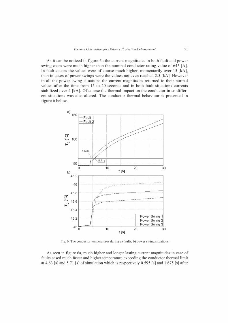
stabilized over 4 [kA]. Of course the thermal impact on the conductor in so differ-
ent situations was also altered. The conductor thermal behaviour is presented in
figure 6 below.
0 10 20 30
50
100
150
t [s]
TC
[oC
]
Fault 1
Fault 2
0 10 20 3045
45.2
45.4
45.6
45.8
46
46.2
t [s]
TC
[oC
]
Power Swing 1
Power Swing 2Power Swing 3
a)
b)
4.63s
5.71s
Fig. 6. The conductor temperatures during a) faults, b) power swing situations
As seen in figure 6a, much higher and longer lasting current magnitudes in case of
faults cased much faster and higher temperature exceeding the conductor thermal limit
at 4.63 [s] and 5.71 [s] of simulation which is respectively 0.595 [s] and 1.675 [s] after
. STASZEWSKI, W. REBIZANT92
the fault happened. This situation highlights the need for fast protection because less
than two seconds are enough for the fault currents to permanently destroy the con-
ductor. However, all three situations of power swing phenomena proven the fact, that
during sufficient weather conditions the continuous transmission line operation is safe
and allowable.
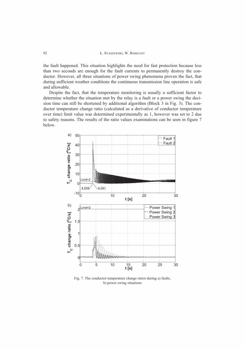
Despite the fact, that the temperature monitoring is usually a sufficient factor to
determine whether the situation met by the relay is a fault or a power swing the deci-
sion time can still be shortened by additional algorithm (Block 3 in Fig. 3). The con-
ductor temperature change ratio (calculated as a derivative of conductor temperature
over time) limit value was determined experimentally as 1, however was set to 2 due
to safety reasons. The results of the ratio values examinations can be seen in figure 7
below.
0 10 20 30-10
0
10
20
30
40
50
t [s]
TC
ch
an
ge r
ati
o [
oC
/s]
Fault 1
Fault 2
Limit=2
0 5 10 15 20 25 30
0
0.5
1
1.5
2
t [s]
TC
ch
an
ge r
ati
o [
oC
/s]
Power Swing 1
Power Swing 2
Power Swing 3
Limit=2
a)
b)
4.039 4.041
Fig. 7. The conductor temperature change ratios during a) faults,
b) power swing situations
Thermal Calculation for Distance Protection Enhancement 93
As it was seen in figure 7, the additional algorithm responsible for conductor tem-
perature change ratio monitoring also perfectly determined between the fault and
power swing situations and as expected operated much faster than the algorithm
monitoring the conductor temperature. The reaction time for the Block 3 was 0.004 [s]
and 0.006 [s] instead of the longer Block 2 reaction times of 0.595 [s] and 1.675 [s]
respectively. The Block 3 reaction times are shorter by the time the conductor needed
to reach the temperature of its thermal limit.
Despite the fact that the Block 3 presented reaction times are shorter than in
case of Block 2, there is a risk that during unstable power swing situation or long-
lasting ones the conductor limit temperature can be exceeded with simultaneously
low ratio of temperature increase causing the conductor damage. That is why for
the best performance both Block 2 and 3 should co-operate with standard protec-
tion relay.
5. CONCLUSIONS
This paper presented the examination of a standard distance protection relay en-
hanced with two additional algorithms based on the Dynamic Thermal Line Rating.
The examination, considering the most important factors: current magnitudes, con-
ductor temperature and conductor temperature change ratio has proven that the
proposed algorithms improved the distance relay operation reaction times and reli-
ability.
Despite the Dynamic Thermal Line Rating application high weather dependency,
in vast number of cases it is very efficient and reliable tool making it worth consider-
ing for the standard distance protection improvements.
The DTLR can also introduce much better transmission line utilization and in-
crease of the transmission system efficiency, bringing additional profits for operators.
It can also improve the system reliability and safety avoiding unnecessary relay op-
erations.
REFERENCES
[1] WISZNIEWSKI A., UNGRAD H., WINKLER W., Protection techniques in electrical energy sys-
tems, New York 1995.
[2] REBIZANT W., SZAFRAN J., WISZNIEWSKI A., Digital Signal Processing in Power System
Protection and Control, Springer Verlag, Series: Signals and Communication Technology, London
2011.
[3] SZAFRAN J., WISZNIEWSKI A., Algorytmy pomiarowe i decyzyjne cyfrowej automatyki elektro-
energetycznej, 2001.
[4] HOROWITZ S.H., PHADKE A.G., Third zone revisited, IEEE Transactions on Power Delivery,
Vol. 21, January 2006, pp. 23–29.
. STASZEWSKI, W. REBIZANT94
[5] YAMASHITA K., LI J., ZHANG P., LIU C.-C., Analysis and Control of Major Blackout Events,
IEEE, 2009.
[6] IEEE Standard for Calculating the Current-Temperature of Bare Overhead Conductors, IEEE Std.
738-2006 (Revision of IEEE Std. 738-1993).
[7] SAMANMIT U., CHUSANAPIPUTT S., PUNGPRASERT V., Increasing of Dynamic Thermal
Rating of Transmission Line, International Conference on Power System Technology, 1–4, 2006.
[8] SMITH S.W., Digital signal processing: A practical guide for engineers and scientists, 2003.