Embed Size (px)
Citation preview
C.A. Nucci
Dept. of Electrical Engineering
University of Bologna
40136 Bologna, [email protected]
F. Rachidi
Swiss Federal Inst. of Technology
Power Systems Laboratory
1015 Lausanne, [email protected]
IEEE ‘99 T&D ConferencePanel session "Distribution Lightning Protection".
New Orleans, April 14, 1999
Lightning-Induced Voltages
1. Aim of Presentation
To give some answers to the questions that are
most commonly raised by engineers and
scientific researchers dealing with the problem of
protection against lightning-induced voltages.
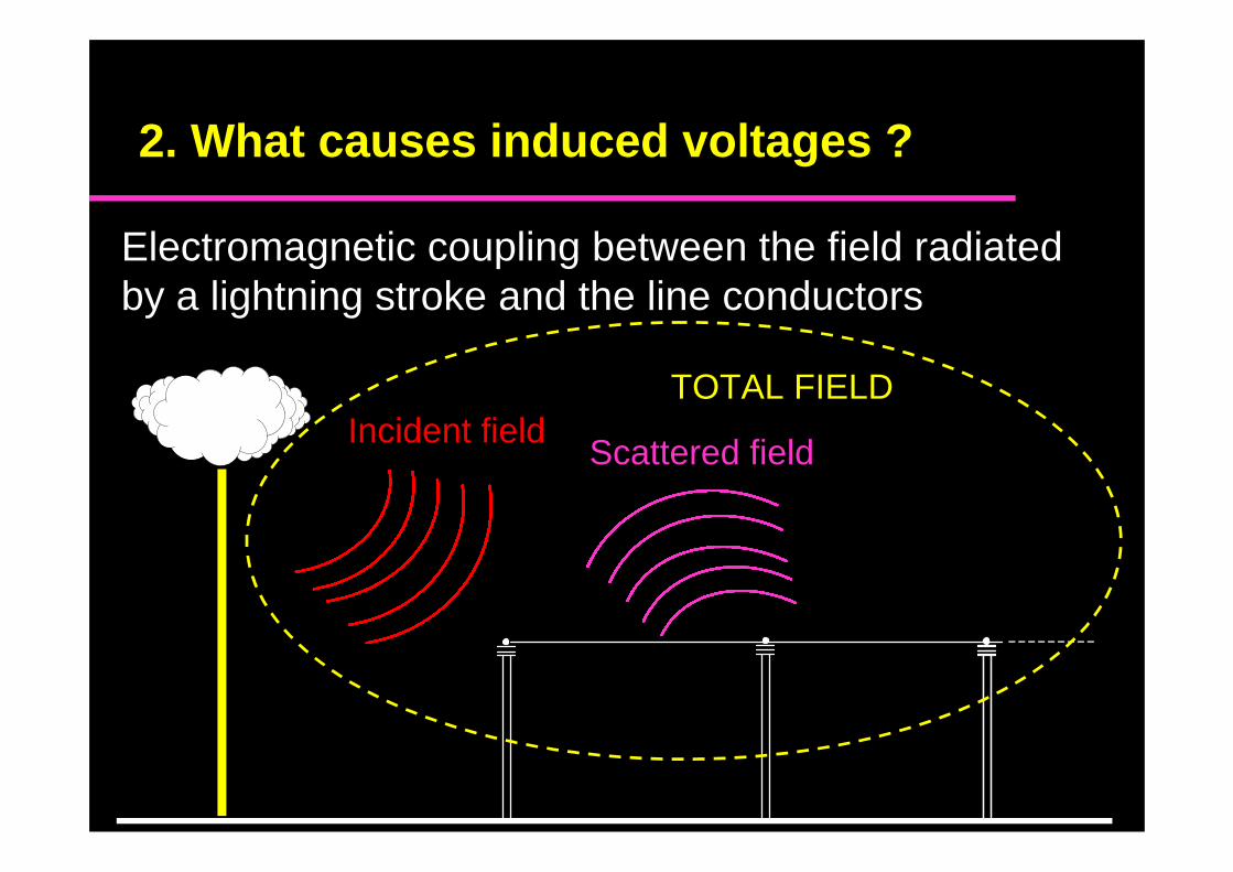
2. What causes induced voltages ?
Electromagnetic coupling between the field radiatedby a lightning stroke and the line conductors
Incident fieldScattered field
TOTAL FIELD
2. What causes induced voltages ? Cont.
Essentially the return-stroke phase is responsible ofthe induced voltage
However, when lightning strikes the ground nearbythe line at close distance from the line, also thepreceding leader phase can results in a significantinduced voltage
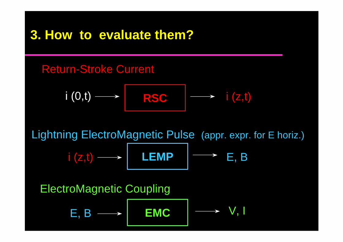
Return-Stroke Current
i (0,t) RSC i (z,t)
Lightning ElectroMagnetic Pulse (appr. expr. for E horiz.)
i (z,t) LEMP E, B
ElectroMagnetic Coupling
E, B EMC V, I
3. How to evaluate them?
A review of the various return-stroke models has beenrecently made by Rakov and Uman onIEEE EMC Transactions, Special Issue on Lightning,1998 where they have discussed, among others, thefollowing ‘engineering’ models
• Bruce-Golde (BG)
• Transmission Line (TL) Uman, McLain, Krider
• Traveling Current Source (TCS) Heidler
• Modified Transm. Line - Linear (MTLL) Rakov and Dulzon
• Modified Transm. Line - Exponential (MTLE) Nucci et al.
• Diendorfer-Uman (DU)
Return-stroke current models
3. How to evaluate them? Cont.
Experimental validation
Given a channel-base current ==>the RSC model must reproduce the corresponding Electromagnetic field
For Natural lightning:
PROBLEM: practically no existing data sets ofsimultaneously measured current and fields
Data of this kind have been collected using
the Triggered lightning technique
Return-stroke current models
3. How to evaluate them? Cont.
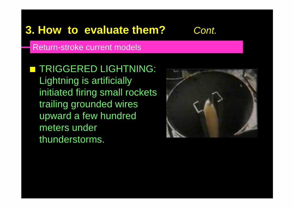
nn TRIGGERED LIGHTNING:TRIGGERED LIGHTNING:Lightning is artificiallyLightning is artificiallyinitiated firing small rocketsinitiated firing small rocketstrailing grounded wirestrailing grounded wiresupwardupward a a few hundred few hundredmetersmeters under underthunderstormsthunderstorms..
Return-stroke current models
3. How to evaluate them? Cont.
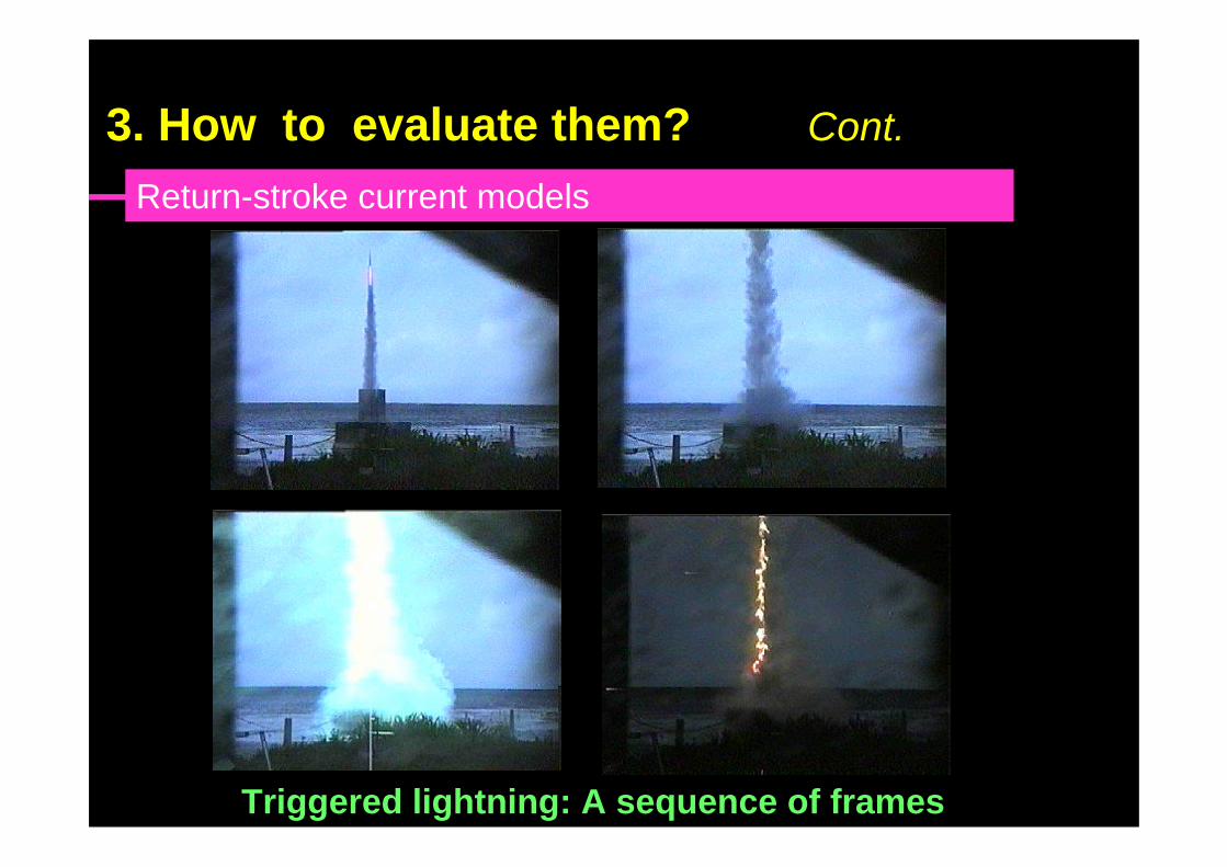
Triggered lightning: A sequence of frames
Return-stroke current models
3. How to evaluate them? Cont.
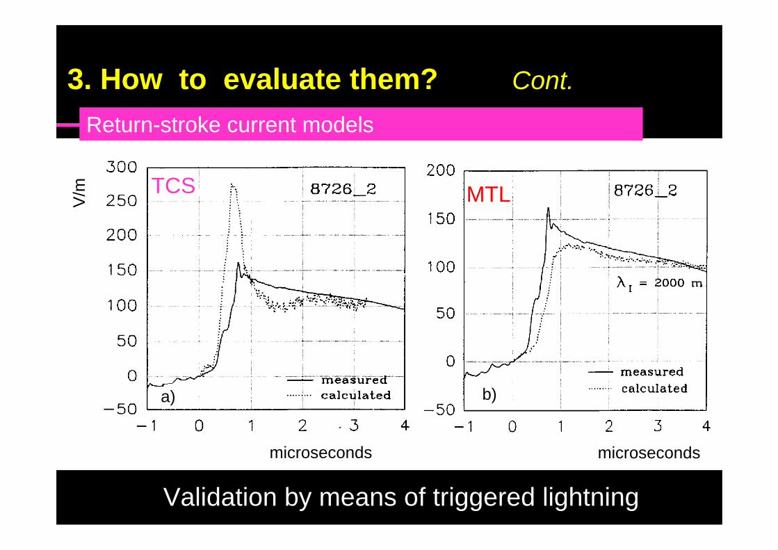
TCS
a) b)
microseconds microseconds
V/m TCS MTL
Validation by means of triggered lightning
Return-stroke current models
3. How to evaluate them? Cont.
Basically, three coupling models have been used:
• Rusck [1958]
• Chowdhuri [1969]
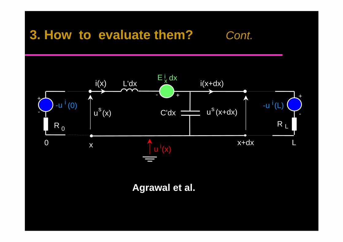
• Agrawal et al. [1980]
Of the three models only the Agrawal one is‘rigorous’ for a general external field excitation
However, for a lightning channel perpendicular tothe ground plane ===> Rusck = Agrawal
Electromagnetic coupling
3. How to evaluate them? Cont.
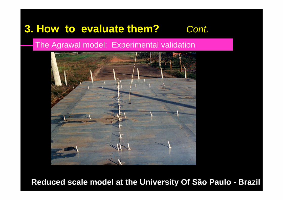
Reduced scale model at the University Of São Paulo - Brazil
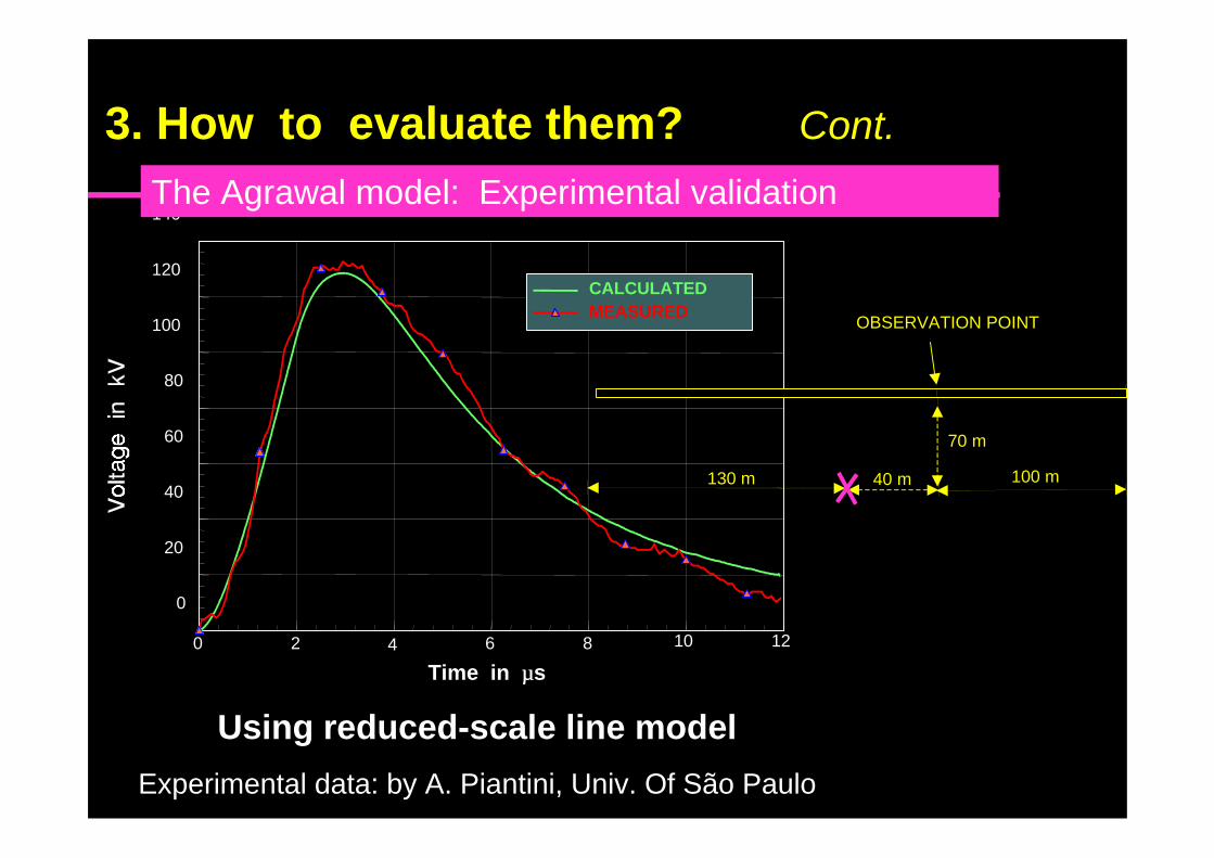
The Agrawal model: Experimental validation
3. How to evaluate them? Cont.
0 2 4 6 8 10 12
Time in µµs
0
20
40
60
80
100
120
140
CALCULATEDMEASURED
Using reduced-scale line model
Experimental data: by A. Piantini, Univ. Of São Paulo
70 m
130 m 40 m 100 m
OBSERVATION POINT
The Agrawal model: Experimental validation
3. How to evaluate them? Cont.
0 0.5 1 1.5 2 2.5 3 3.5 4Time in us
-60
-40
-20
0
20
40
60
80
100
120
140
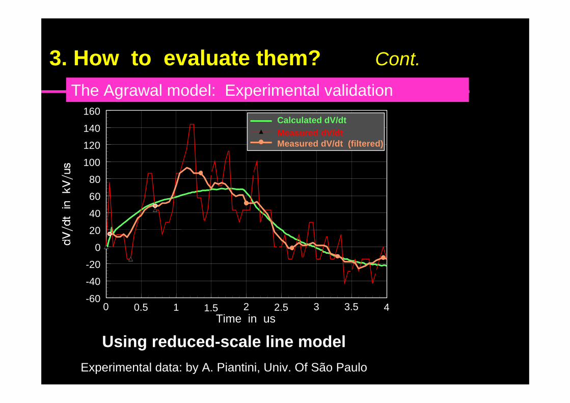
160Calculated dV/dt
Measured dV/dtMeasured dV/dt (filtered)
The Agrawal model: Experimental validation
Using reduced-scale line model
Experimental data: by A. Piantini, Univ. Of São Paulo
3. How to evaluate them? Cont.
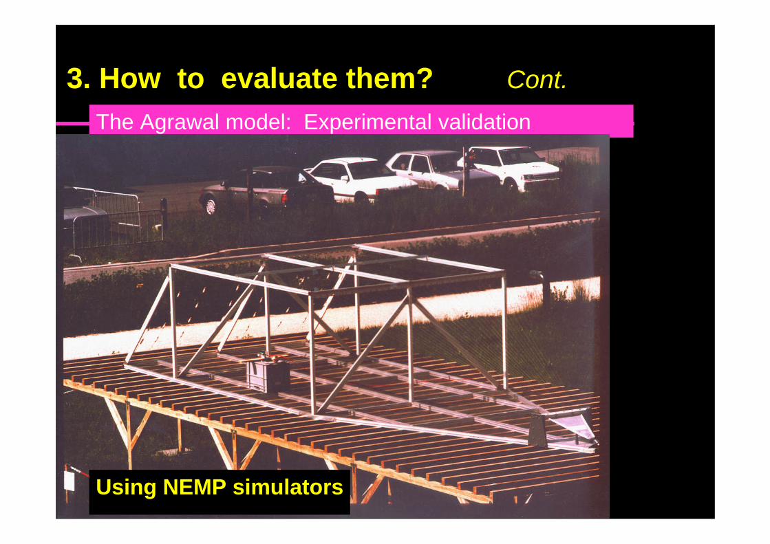
The Agrawal model: Experimental validation
3. How to evaluate them? Cont.
Using NEMP simulators
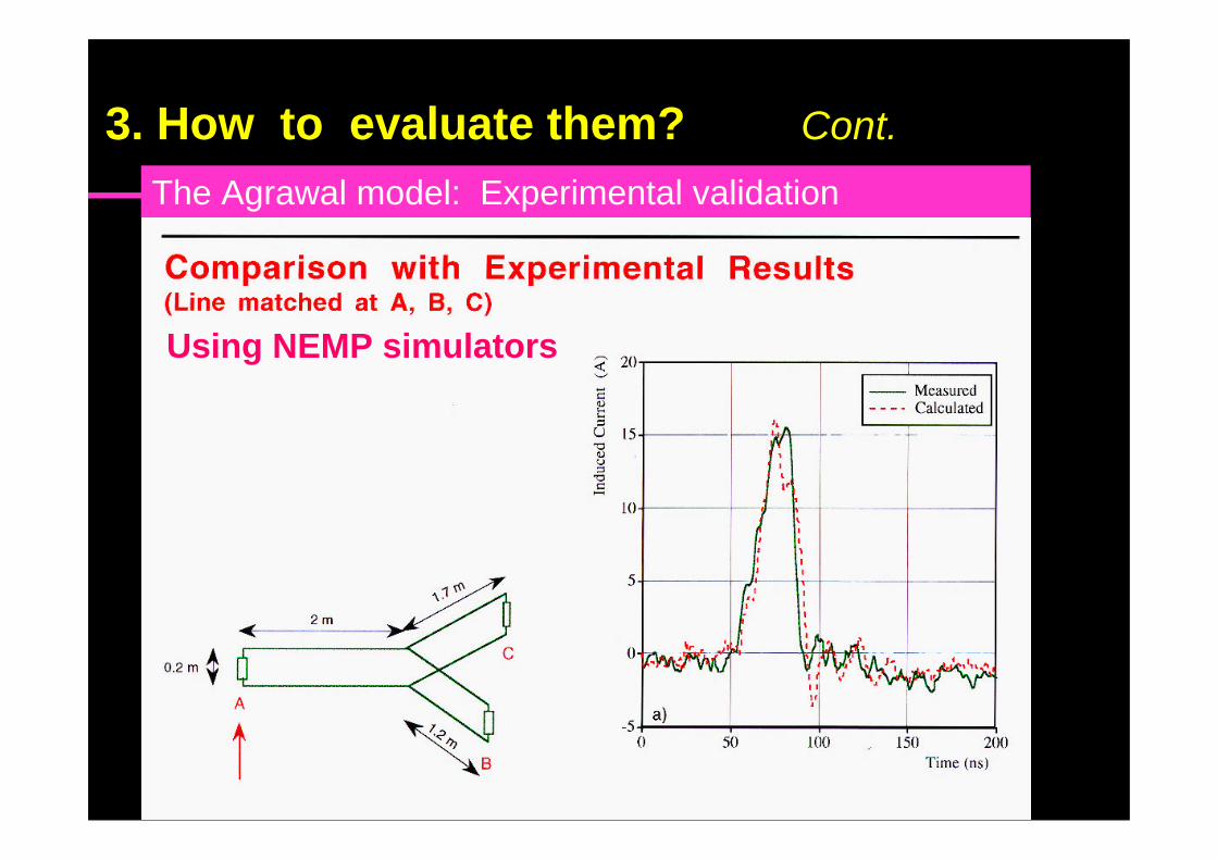
The Agrawal model: Experimental validation
3. How to evaluate them? Cont.
Using NEMP simulators
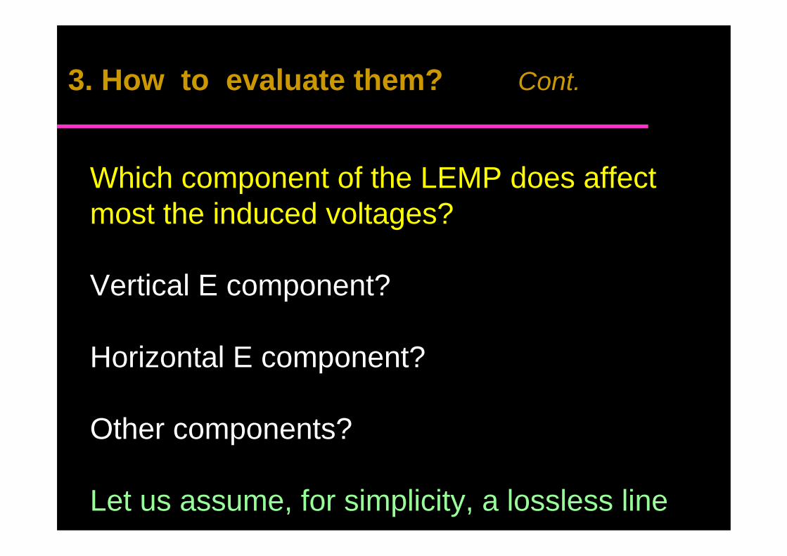
Which component of the LEMP does affectmost the induced voltages?
Vertical E component?
Horizontal E component?
Other components?
Let us assume, for simplicity, a lossless line
3. How to evaluate them? Cont.
0
u (x)
i(x) L'dx
x x+dx
+-
i(x+dx)
+
-
+
-
L
us (x+dx)-u i (0)
R 0
-u i (L)
R L
u i(x)
iE x dx
s C'dx
Agrawal et al.
3. How to evaluate them? Cont.
0
u (x)
i(x) L'dx
x x+dx
+-
i(x+dx)
+
-
+
-
L
us (x+dx)-u i (0)
R 0
-u i (L)
R L
u i(x)
iE x dx
s C'dx
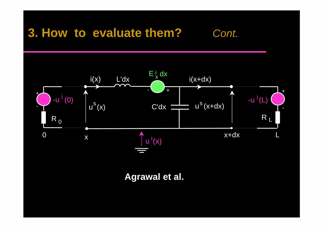
Agrawal et al.
3. How to evaluate them? Cont.
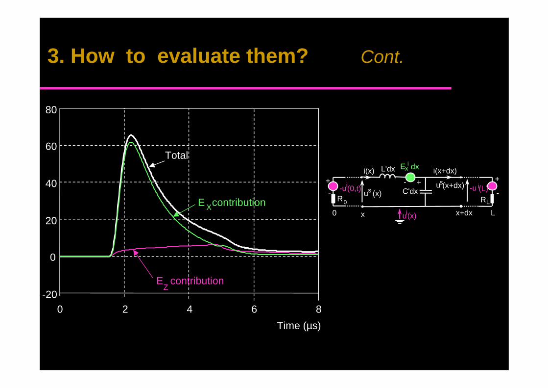
-20
0
20
40
60
80
0 2 4 6 8
Time (µs)
E contribution
E contribution
Total
X
Z
0
u (x)
i(x) L'dx
x x+dx
+-i(x+dx)
+
-
+
-
L
us(x+dx)-ui(0,t)R0
-u i(L)RL
ui(x)
iEx dx
s C'dx
3. How to evaluate them? Cont.
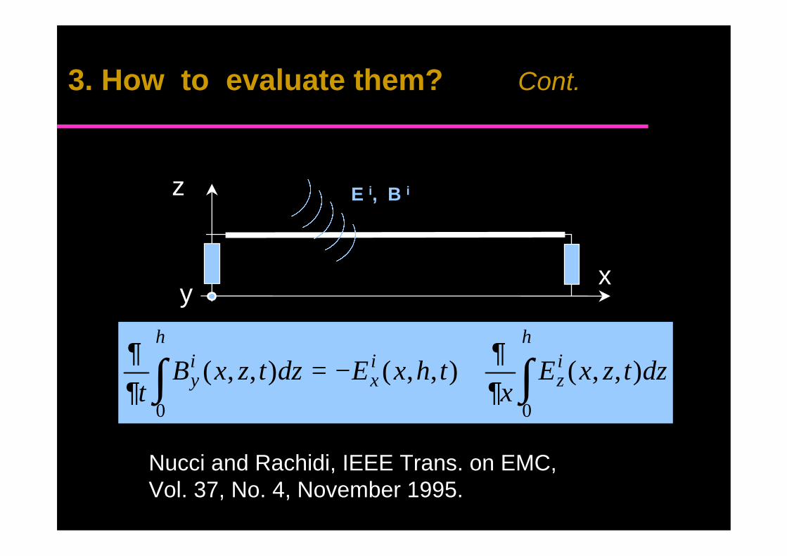
∫∫ +−=h
iz
ix
hiy dztzxE
xthxEdztzxB
t00
),,(),,(),,(∂∂
∂∂
Nucci and Rachidi, IEEE Trans. on EMC,Vol. 37, No. 4, November 1995.
z
xy
E i, B i
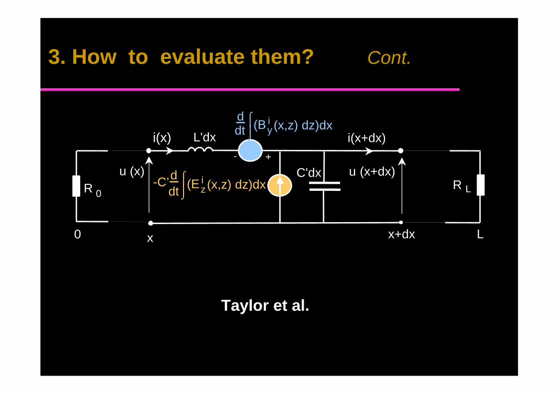
3. How to evaluate them? Cont.
0
u (x)
i(x) L'dx
x x+dx
+-
i(x+dx)
L
u (x+dx)R 0
R L
i(B y (x,z) dz)dx
C'dx
⌠⌡
ddt
i(E z (x,z) dz)dx⌠ddt⌡
-C’
Taylor et al.
3. How to evaluate them? Cont.
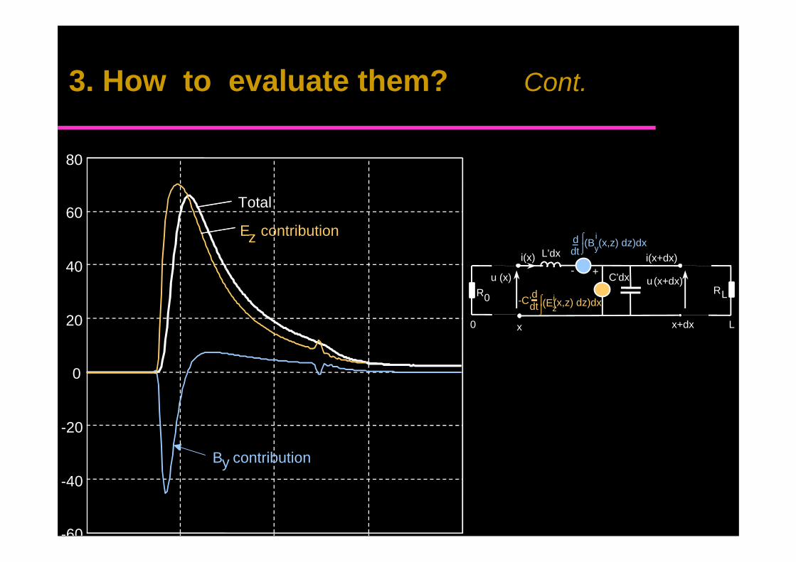
-60
-40
-20
0
20
40
60
80
B contribution
E contribution
Total
z
y
0
u (x)
i(x) L'dx
x x+dx
+-i(x+dx)
L
u(x+dx)R0
RL
i(B y(x,z) dz)dx
C'dx
⌠⌡
ddt
i(E z(x,z) dz)dx⌠ddt⌡
-C’
3. How to evaluate them? Cont.
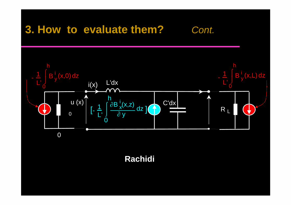
0
iB y (x,L)⌠⌡
1L’
-
h
dz
0
u (x)
i(x) L'dx
0R L
C'dxiB x(x,z)⌠⌡
∂∂ y
1L’
0
-
h
dz[ ]
0
iB y (x,0)⌠⌡
1L’
-
h
dz
Rachidi
3. How to evaluate them? Cont.
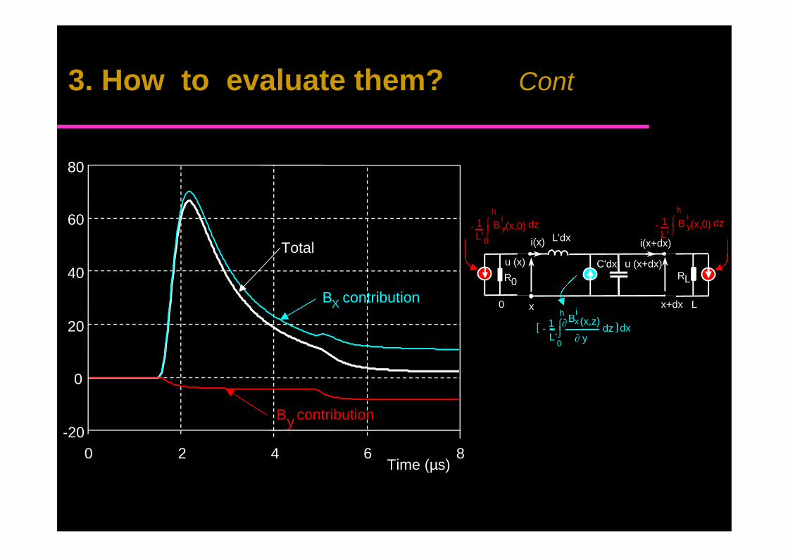
-20
0
20
40
60
80
0 2 4 6 8Time (µs)
B contribution
B contribution
Total
X
y
0
iB y(x,0)⌠
⌡1L’
-
h
dz
0
u (x)
i(x) L'dx
x x+dx
i(x+dx)
L
u (x+dx)R0 RL
C'dx
iB y(x,0)⌠
⌡1L’
-
h
dz
iBx (x,z)⌠
⌡∂
∂ y1L’
0
-
h
dz[ ] dx
3. How to evaluate them? Cont
The contribution of a given electromagnetic fieldcomponent in the coupling mechanism dependsstrongly on the used model.
Thus, when speaking about the contribution of agiven electromagnetic field component to theinduced voltages, one has to specify the coupling
.
3. ? Cont.
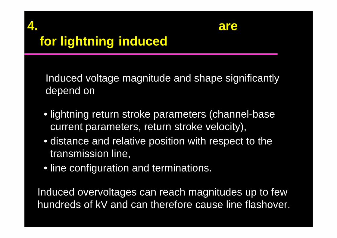
Induced voltage magnitude and shape significantlydepend on
• lightning return stroke parameters (channel-basecurrent parameters, return stroke velocity),
• distance and relative position with respect to thetransmission line,
• line configuration and terminations.
Induced overvoltages can reach magnitudes up to fewhundreds of kV and can therefore cause line flashover.
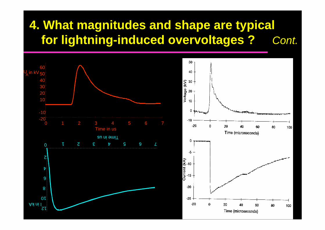
4. are for lightning induced
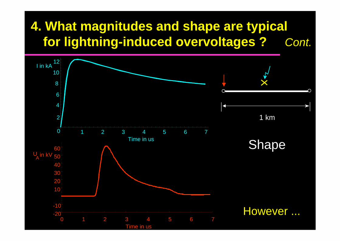
1 2 3 4 5 6 7
12I in kA
Time in us
10
8
6
4
2
0
-20-10
10
203040
5060
0 1 2 3 4 5 6 7Time in us
UA in kV
1 km
Shape
4. What magnitudes and shape are typicalfor lightning-induced overvoltages ? Cont.
However ...
1 2 3 4 5 6 7
12I in kA
Time in us
10
8
6
4
2
0
-20-10
102030405060
0 1 2 3 4 5 6 7Time in us
UA in kV
4. What magnitudes and shape are typicalfor lightning-induced overvoltages ? Cont.
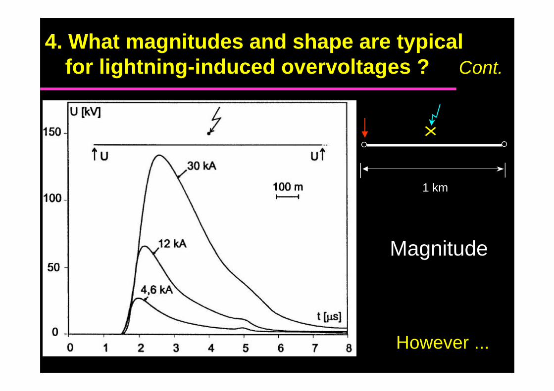
Magnitude
1 km
4. What magnitudes and shape are typicalfor lightning-induced overvoltages ? Cont.
However ...
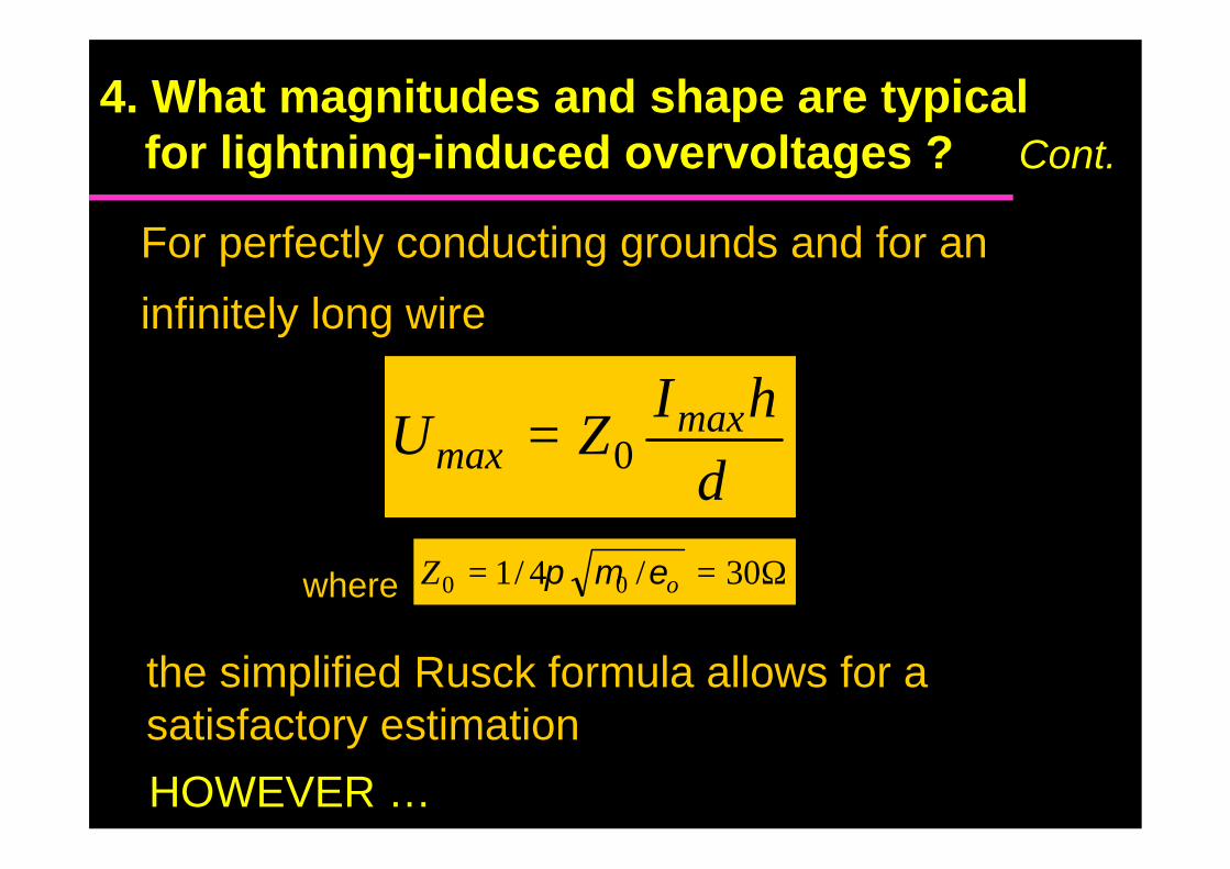
For perfectly conducting grounds and for an
infinitely long wire
4. What magnitudes and shape are typicalfor lightning-induced overvoltages ? Cont.
the simplified Rusck formula allows for asatisfactory estimation
d
hIZU max
max 0=
Ω== 30/4/1 00 oZ εµπwhere
HOWEVER …
5.How far away can lightning strokes be thatcause an induced voltage flashover ?
Generally within 200 m
However it depends on many parameters(=> computer code)
Lightning strokes occurring beyond a fewhundred meters from the line can cause a lineflashover for poor conducting soils (De LaRosa et al., IEEE Trans. on PWDR, 1988)
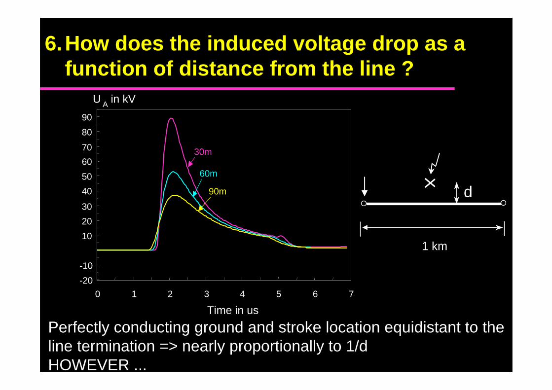
6.How does the induced voltage drop as afunction of distance from the line ?
-20
-10
10
20
30
40
50
60
70
80
90
0 1 2 3 4 5 6 7
Time in us
U A in kV
30m
60m
90m
Perfectly conducting ground and stroke location equidistant to theline termination => nearly proportionally to 1/dHOWEVER ...
1 km
d
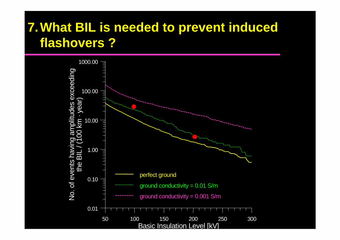
7.What BIL is needed to prevent inducedflashovers ?
50 100 150 200 250 300Basic Insulation Level [kV]
0.01
0.10
1.00
10.00
100.00
1000.00
No.
of e
vent
s ha
ving
am
pli tu
des
exce
edin
gth
e B
IL /
( 100
km
· ye
a r)
perfect ground
ground conductivity = 0.01 S/m
ground conductivity = 0.001 S/m
8.What arrester spacing is needed to preventflashover?
In order to prevent direct-stroke flashover, arresterspacings of 300-400 m is generally recommended.
For the case of induced flashovers, a givenconfiguration of line arresters can result in differentperformances depending on the location of lightningstrike [29].
Further studies are needed in this respect.

8.What arrester spacing is needed to preventflashover?
X0 X1 X2 X3 X4 X50
20
40
60
80
100
120
Transf.Transf. + Surge arr.Matched
Stroke location: B1
a)

8.What arrester spacing is needed to preventflashover?
X0 X1 X2 X3 X4 X50
50
100
150
200
250
300
350
400
Transf.Transf. + Surge arr.Matched
Stroke location: E1
b)
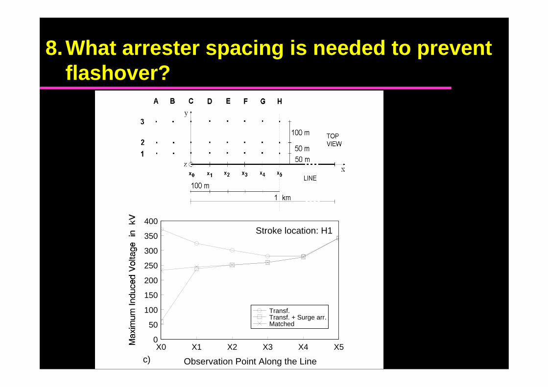
8.What arrester spacing is needed to preventflashover?
X0 X1 X2 X3 X4 X5
Observation Point Along the Line
0
50
100
150
200
250
300
350
400
Transf.Transf. + Surge arr.Matched
Stroke location: H1
c)
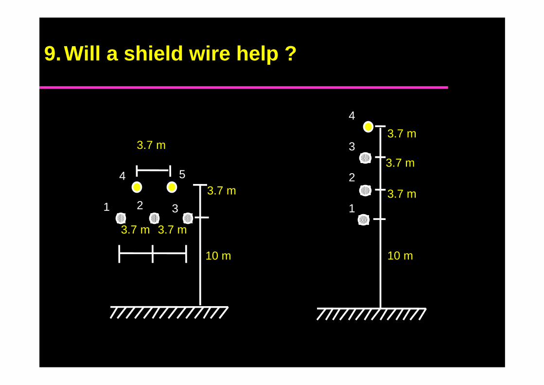
a)
1
2
3
10 m
3.7 m
3.7 m
3.7 m
4
1 2 3
3.7 m 3.7 m
10 m
4 5
3.7 m
3.7 m
b)
9.Will a shield wire help ?
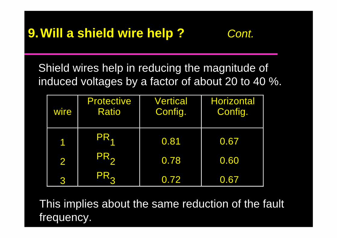
9.Will a shield wire help ? Cont.
Shield wires help in reducing the magnitude ofinduced voltages by a factor of about 20 to 40 %.
This implies about the same reduction of the faultfrequency.
wireProtective
RatioVerticalConfig.
HorizontalConfig.
1
2
3
PR1PR2PR3
0.81
0.78
0.72
0.67
0.60
0.67
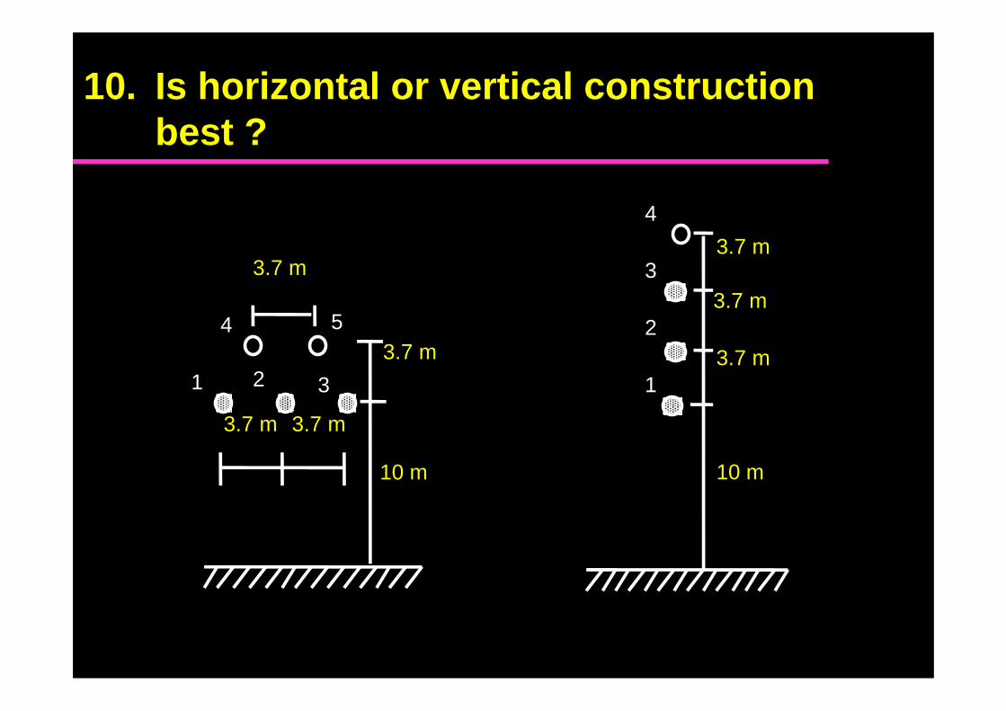
10. Is horizontal or vertical construction best ?
a)
1
2
3
10 m
3.7 m
3.7 m
3.7 m
4
1 2 3
3.7 m 3.7 m
10 m
4 5
3.7 m
3.7 m
b)
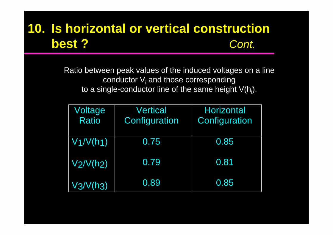
10. Is horizontal or vertical construction best ? Cont.
a)
VoltageRatio
VerticalConfiguration
HorizontalConfiguration
V1/V(h1)
V2/V(h2)
V3/V(h3)
0.75
0.79
0.89
0.85
0.81
0.85
Ratio between peak values of the induced voltages on a lineconductor Vi and those corresponding
to a single-conductor line of the same height V(hi).
The induced voltage magnitude for typical distributionlines is virtually proportional to the line height.
As a consequence, an important factor determining themagnitude of lightning-induced voltage is the lineheight above ground, rather than the type ofconstruction.
In general, a construction allowing a shorter height forthe conductors is epected to experience lower inducedovervoltages.
10. Is horizontal or vertical construction best ? Cont.
11. What effect does pole grounding andground resistivity have ?
Pole grounding affects the performance of the groundwire in reducing the induced overvoltages.
In general, lower the pole ground impedance, betterthe performance of the ground wire.
Influence of pole grounding
The ground resistivity affects:
1. electromagnetic field
2. propagation of the surges
Influence of ground resistivity
11.What effect does pole grounding andground resistivity have ? Cont.
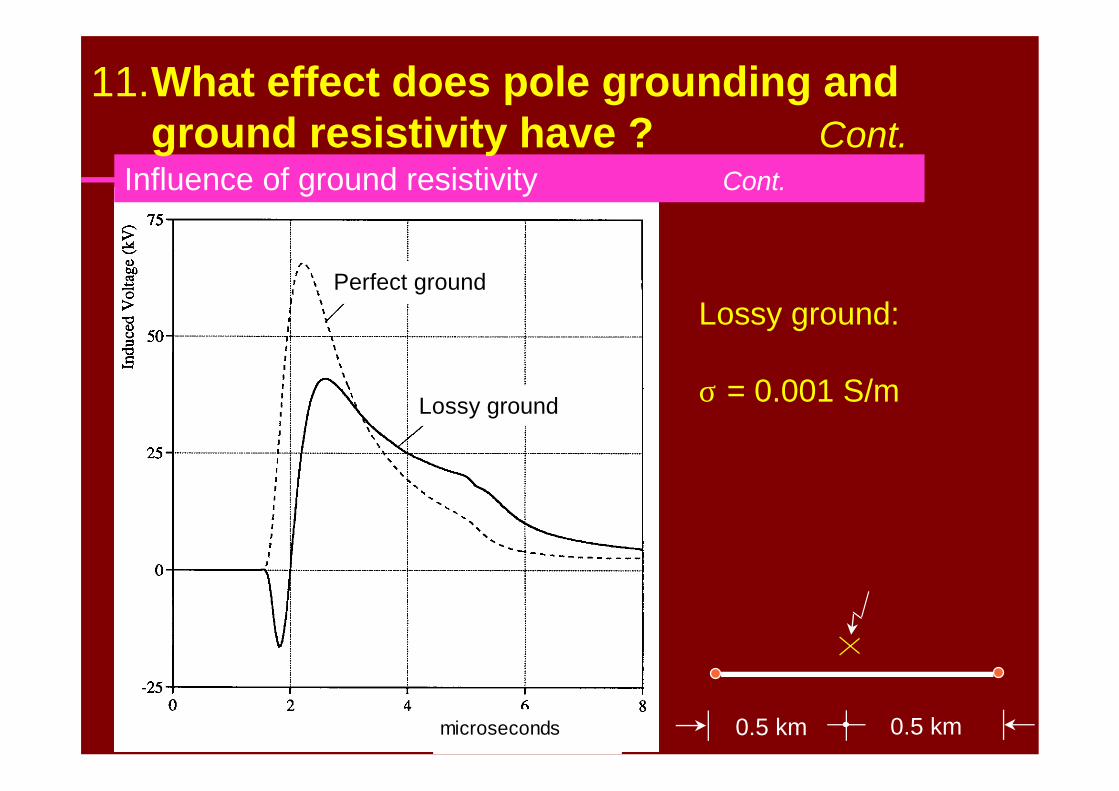
Lossy ground
Perfect ground
microseconds 0.5 km 0.5 km
Lossy ground:
σ = 0.001 S/m
Influence of ground resistivity Cont.
11.What effect does pole grounding andground resistivity have ? Cont.
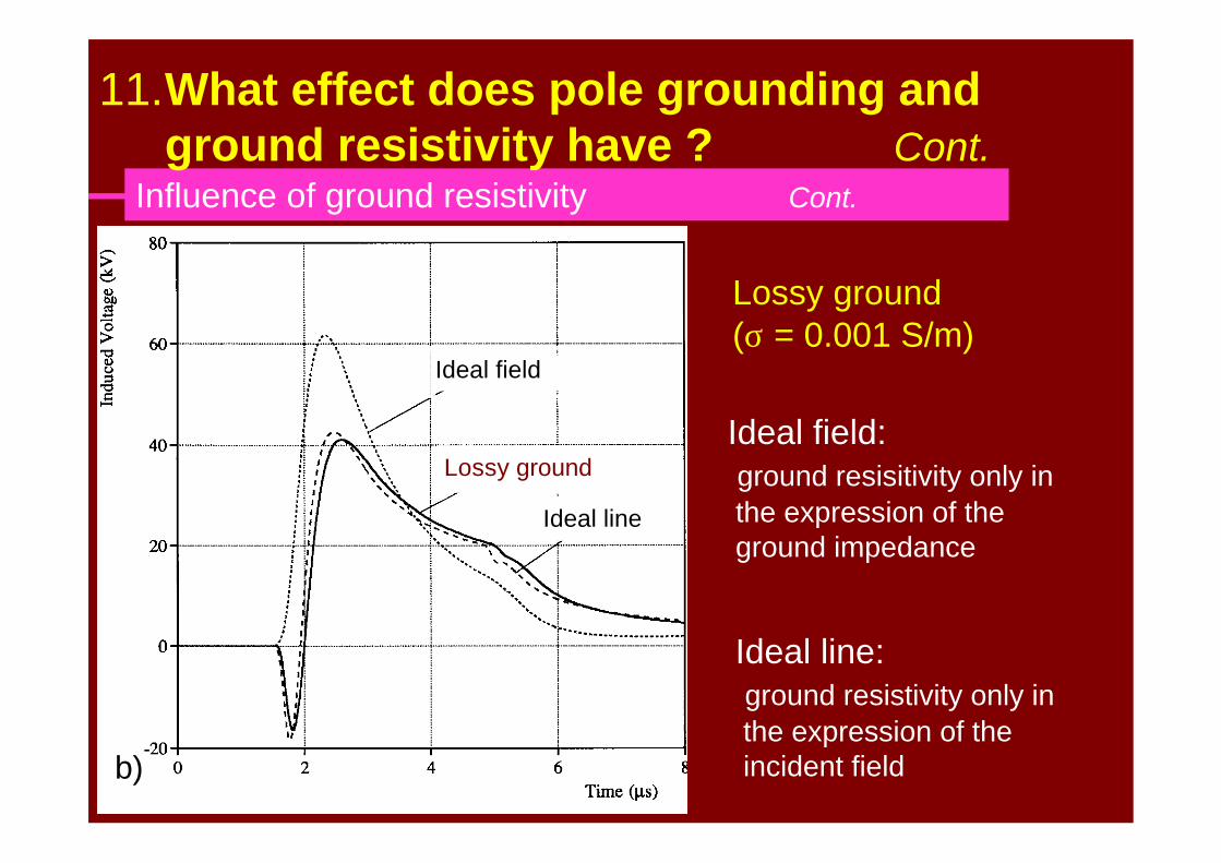
b)
Ideal field
Ideal line
Lossy ground
Lossy ground(σ = 0.001 S/m)
Ideal field: ground resisitivity only in the expression of the ground impedance
Ideal line: ground resistivity only in the expression of the incident field
Influence of ground resistivity Cont.
11.What effect does pole grounding andground resistivity have ? Cont.
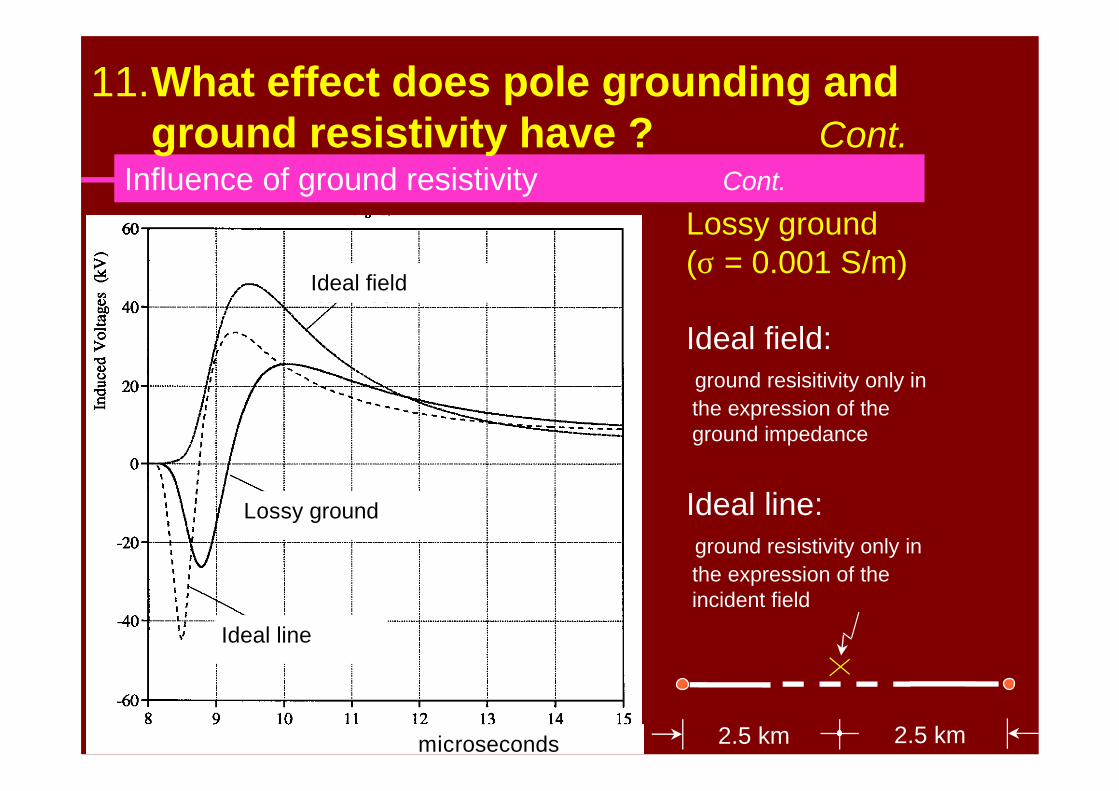
Lossy ground
Ideal line
Ideal field
microseconds 2.5 km 2.5 km
Lossy ground(σ = 0.001 S/m)
Ideal field: ground resisitivity only in the expression of the ground impedance
Ideal line: ground resistivity only in the expression of the incident field
Influence of ground resistivity Cont.
11.What effect does pole grounding andground resistivity have ? Cont.
How does the ground resistivity affectmagnitude and shape of the inducedvoltages?
Influence of ground resistivity
11.What effect does pole grounding andground resistivity have ? Cont.
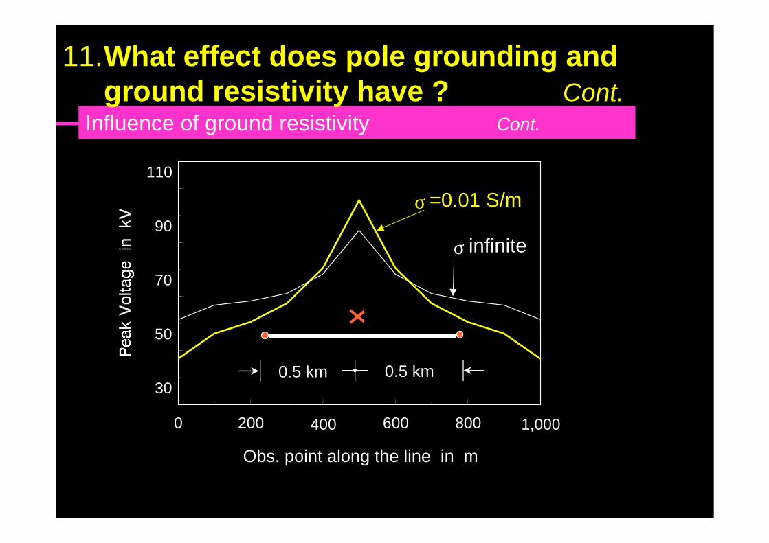
0.5 km 0.5 km
Influence of ground resistivity Cont.
0 200 400 600 800 1,000
Obs. point along the line in m
30
50
70
90
110
σ infinite
σ =0.01 S/m
11.What effect does pole grounding andground resistivity have ? Cont.
1 km
Influence of ground resistivity Cont.
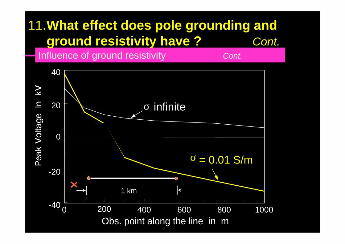
0 200 400 600 800 1000Obs. point along the line in m
-40
-20
0
20
40
σ infinite
σ = 0.01 S/m
11.What effect does pole grounding andground resistivity have ? Cont.
The ground resistivity can increase or
decrease the magnitude of the induced
voltages depending on the stroke location
and the observation point along the line
=> the calculation is not trivial
Influence of ground resistivity Cont.
11.What effect does pole grounding andground resistivity have ? Cont.
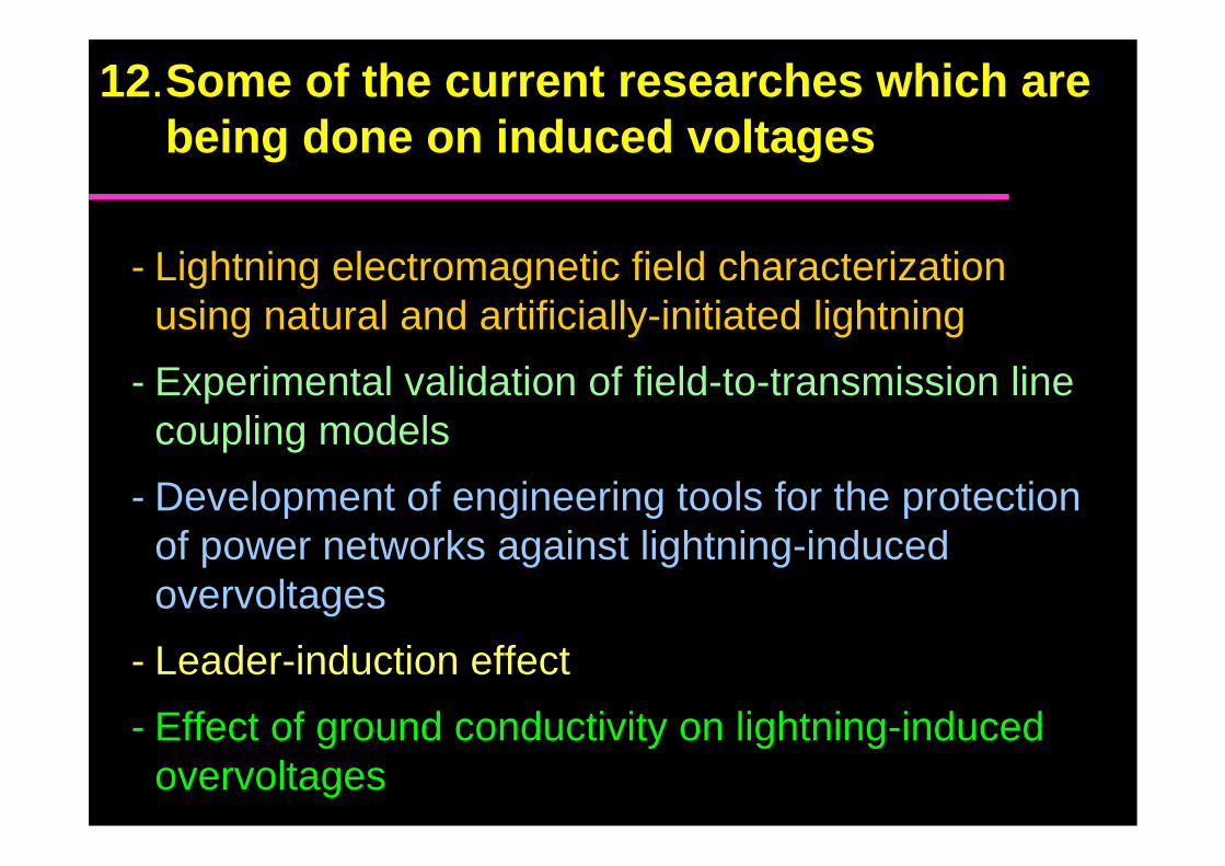
- Lightning electromagnetic field characterizationusing natural and artificially-initiated lightning
- Experimental validation of field-to-transmission linecoupling models
- Development of engineering tools for the protectionof power networks against lightning-inducedovervoltages
- Leader-induction effect
- Effect of ground conductivity on lightning-inducedovervoltages
12.Some of the current researches which are being done on induced voltages
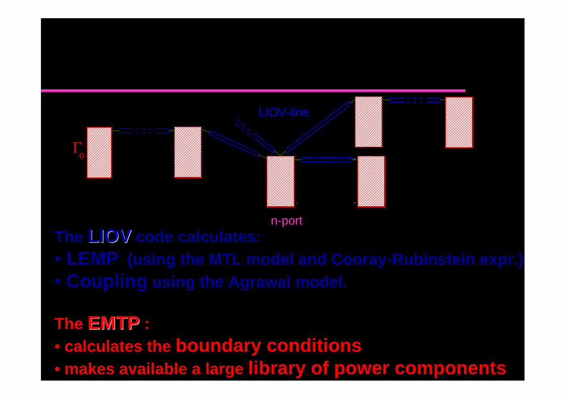
The LIOV-EMTP code
The LIOVLIOV code calculates:
• LEMP (using the MTL model and Cooray-Rubinstein expr.)
• Coupling using the Agrawal model.
The EMTPEMTP :
• calculates the boundary conditions• makes available a large library of power components
Γ0
LIOV-line
n-port
OverheadDistribution Line
The LIOV-EMTP code Cont’d
LIOV has been developped within the framework of an international collaboration involving
• University of Bologna• Swiss federal Institute of Technology (EPFL, Lausanne)• University of Roma ‘La Sapienza’
Its link with EMTP has been realized in collaboration with ENEL-CESI (Univ. Bologna)
Other methods have been proposed EdF (EPFL )
0
u (x,t)
i(x,t) L'dx
C'dx
x x+dx
+-i(x+dx,t)
u (x+dx,t)
u i (x,t)
E ix
(x,h,t)dx
ss
+
-
Γ0
i0 u 0
-u i(0,t)
u u u u E x t dzt s i szi
h= + = − ∫ ( , )
0
i2i1Γ
i0
u 1 u 2
linea Bergeron linea LIOV
+
-
0
u 1'i0 '
-u i(0,t)
Bergeronline
LIOV line
i 0Z
+
-
u 1
V
+
-
+
-
Γi2i1
u 2
V11'
0 Z cc
u1 '
'i0
-u i (0,t)
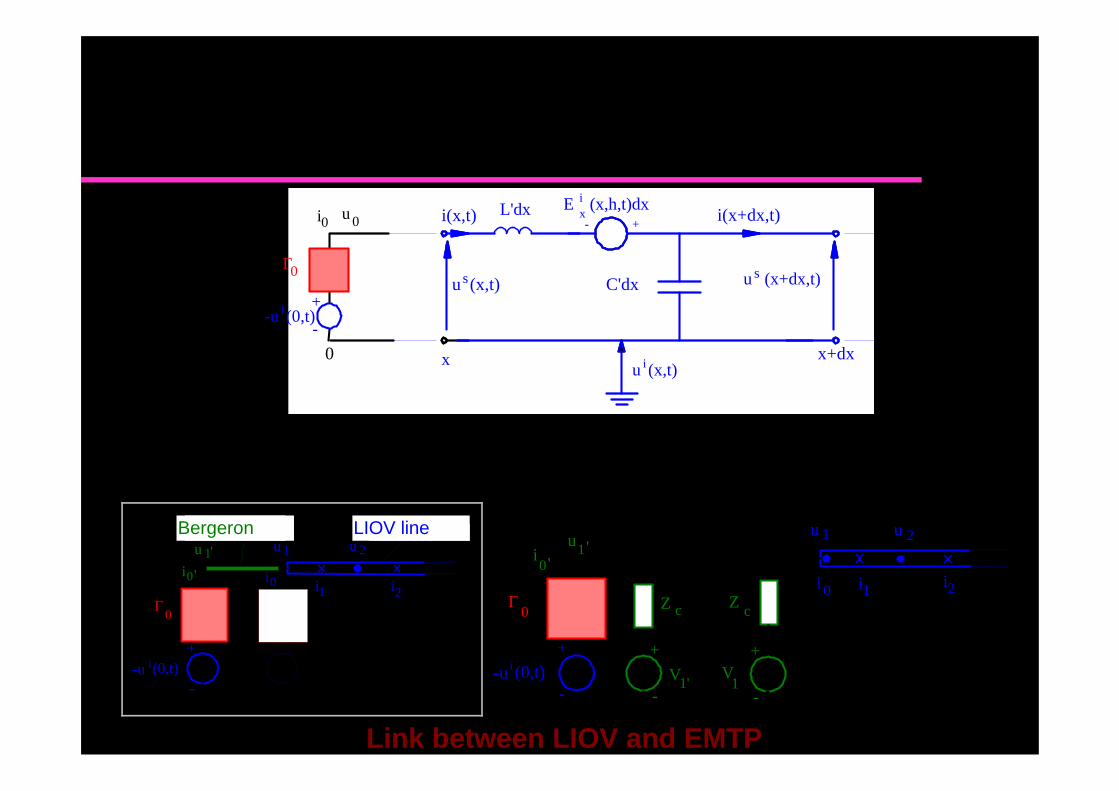
Link between LIOV and EMTP
The LIOV-EMTP code Cont’d
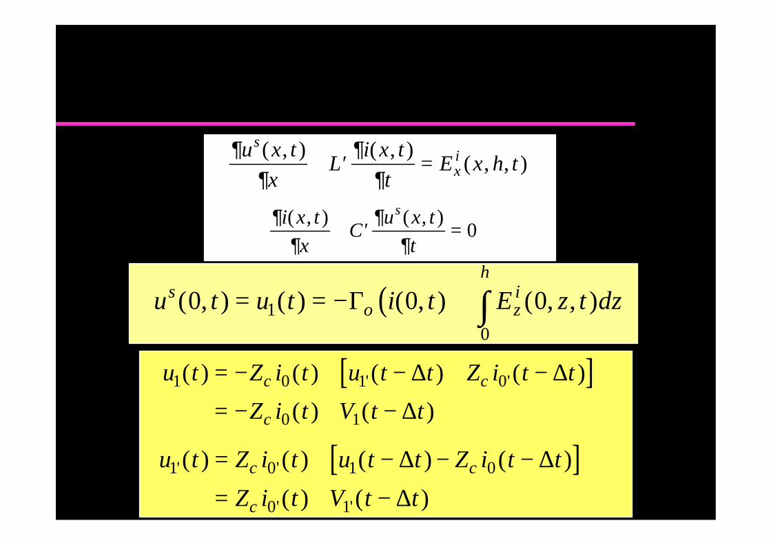
∂∂
∂∂
u x t
xL
i x t
tE x h t
s
xi( , ) ( , )( , , )+ ′ =
∂∂
∂∂
i x t
xC
u x t
t
s( , ) ( , )+ ′ = 0
( )u t u t i t E z t dzso z
ih
( , ) ( ) ( , ) ( , , )0 0 010
= = − + ∫Γ
[ ]u t Z i t u t t Z i t t
Z i t V t tc c
c
1 0 1 0
0 1
( ) ( ) ( ) ( )
( ) ( )' '= − + − + −
= − + −
∆ ∆
∆
[ ]u t Z i t u t t Z i t t
Z i t V t tc c
c
1 0 1 0
0 1
' '
' '
( ) ( ) ( ) ( )
( ) ( )
= + − − −
= + −
∆ ∆
∆
The LIOV-EMTP code Cont’d
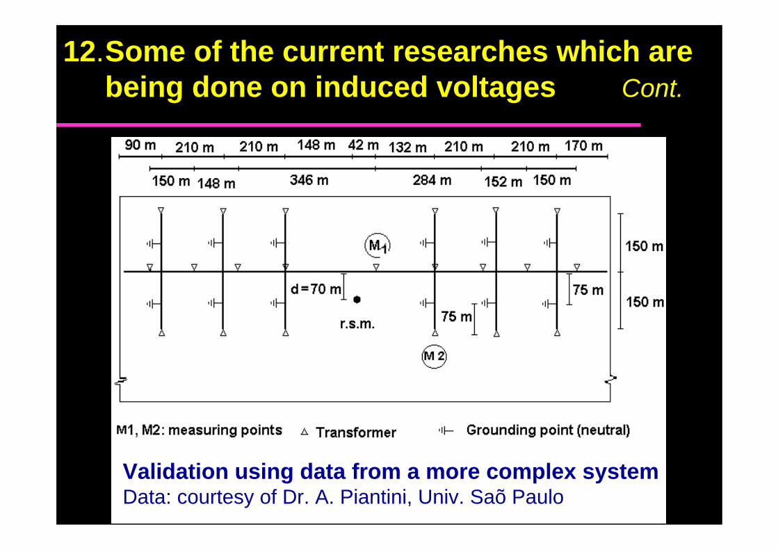
Validation using data from a more complex systemData: courtesy of Dr. A. Piantini, Univ. Saõ Paulo
12.Some of the current researches which are being done on induced voltages Cont.
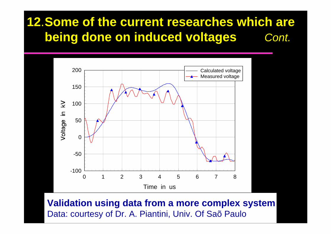
0 1 2 3 4 5 6 7 8
Time in us
-100
-50
0
50
100
150
200 Calculated voltageMeasured voltage
Validation using data from a more complex systemData: courtesy of Dr. A. Piantini, Univ. Of Saõ Paulo
12.Some of the current researches which are being done on induced voltages Cont.
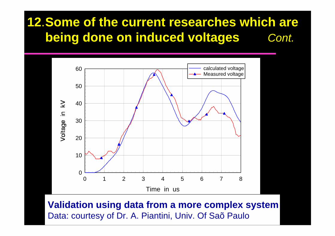
0 1 2 3 4 5 6 7 8
Time in us
0
10
20
30
40
50
60 calculated voltageMeasured voltage
Validation using data from a more complex systemData: courtesy of Dr. A. Piantini, Univ. Of Saõ Paulo
12.Some of the current researches which are being done on induced voltages Cont.
- Return stroke modeling and influence of elevatedstrike objects on lightning current and radiated fields
- Adequacy of the available lightning return strokecurrent statistical data
- Effect of corona on lightning-induced voltages
- Lightning detection and location systems
- Lightning channel tortuosity and inclination
12.Some of the current researches which are being done on induced voltages Cont.
13.What is the CIGRE working group doing oninduced voltages ?
Within the framework ofCIGRE working group WG 33.01 "Lightning",
Task Force 33.01.01 "Lightning induced voltages"established some years ago.
C.A. Nucci (responsible member), P. Chowdhuri, G. V.Cooray, M.T. Correia de Barros, M. Darveniza, F. De la Rosa,G. Diendorfer, F. Heidler, M. Ishii, W. Janischewskyj, T.Kawamura, C. Mazzetti, P. Pettersson, F. Rachidi, V. Rakov,M. Rubinstein, T. Short, J.V. Shostak, M.A. Uman, S.Yokoyama
13.What is the CIGRE working group doing oninduced voltages ?
TF 33.01.01 has already produced two paperspublished in Electra dealing respectively withlightning return stroke models (August 95) andlightning electromagnetic field-to-transmission linecoupling models (October 95).
A third paper, dealing with a sensitivity analysis andaimed at providing ranges of overvoltage values tobe expected in the different typical lineconfigurations, is in preparation.