Embed Size (px)
Citation preview
Drive Technology \ Drive Automation \ System Integration \ Services
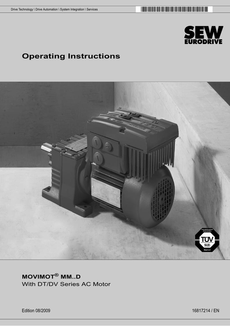
Operating Instructions
MOVIMOT® MM..D With DT/DV Series AC Motor
Edition 08/2009 16817214 / EN

SEW-EURODRIVE—Driving the world
Operating Instructions – MOVIMOT® MM..D With DT/DV Series AC Motor 3
Content
Content1 General Information ............................................................................................ 5
1.1 How to use the operating instructions......................................................... 51.2 Structure of the safety notes ....................................................................... 51.3 Right to claim under limited warranty.......................................................... 61.4 Exclusion of liability..................................................................................... 61.5 Copyright notice .......................................................................................... 6
2 Safety Notes ........................................................................................................ 72.1 General information .................................................................................... 72.2 Target group ............................................................................................... 72.3 Designated use ........................................................................................... 72.4 Other applicable documentation ................................................................. 82.5 Transportation, storage............................................................................... 82.6 Installation................................................................................................... 82.7 Electrical Connection .................................................................................. 92.8 Safe disconnection...................................................................................... 92.9 Operation .................................................................................................... 9
3 Unit Structure .................................................................................................... 103.1 MOVIMOT® inverter.................................................................................. 103.2 Unit designations ...................................................................................... 12
4 Mechanical Installation..................................................................................... 154.1 MOVIMOT® gearmotor ............................................................................. 154.2 MLU11A / MLU21A / MLG..A option ........................................................ 174.3 MLU13A option ......................................................................................... 184.4 URM/BGM option...................................................................................... 194.5 Installation MBG11A ................................................................................. 204.6 MWA21A option ........................................................................................ 214.7 Installing the MOVIMOT® inverter close to the motor ............................... 224.8 Tightening torques .................................................................................... 23
5 Electrical Installation ........................................................................................ 255.1 Installation instructions.............................................................................. 255.2 Connection of MOVIMOT®........................................................................ 305.3 MOVIMOT ® plug connectors ................................................................... 315.4 MOVIMOT®/motor connection – Mounting close to the motor.................. 325.5 Connecting the MOVIMOT® options ........................................................ 365.6 Connection of RS-485 bus master............................................................ 42
4 Operating Instructions – MOVIMOT® MM..D With DT/DV Series AC Motor
Content
6 Startup................................................................................................................ 436.1 Important notes on startup ........................................................................ 436.2 Description of the controls ........................................................................ 446.3 Description of the DIP switches S1........................................................... 466.4 Description of DIP switches S2................................................................. 486.5 Selectable additional functions of MM..D-503-00 ..................................... 516.6 Startup with binary control ........................................................................ 766.7 Startup with options MBG11A or MLG..A ................................................. 786.8 Startup with option MWA21A (speed control module) .............................. 806.9 Supplementary notes for installation close to the motor .......................... 83
7 Startup with RS-485 Interface/Fieldbus .......................................................... 867.1 Important notes on startup ........................................................................ 867.2 Startup procedure ..................................................................................... 867.3 Coding of process data ............................................................................. 897.4 Function with RS-485 master.................................................................... 94
8 Operation ........................................................................................................... 998.1 Operating display ...................................................................................... 998.2 Drive-ID module ...................................................................................... 1008.3 Keypads MBG11A and MLG..A .............................................................. 1018.4 MWA21A setpoint generator................................................................... 102
9 Service ............................................................................................................. 1039.1 Status and error display .......................................................................... 1039.2 Replacing units ....................................................................................... 1069.3 Turning the modular terminal box ........................................................... 1089.4 SEW Service........................................................................................... 1109.5 Extended storage.................................................................................... 1119.6 Disposal .................................................................................................. 111
10 Technical Data ................................................................................................ 11210.1 Motor with operating point 400 V / 50 Hz or 400 V / 100 Hz................... 11210.2 Motor with operating point 460 V / 60 Hz................................................ 11410.3 Motor with operating point 230 V / 50 Hz................................................ 11610.4 Technical data of options ........................................................................ 11810.5 Integrated RS-485 interface.................................................................... 12110.6 Diagnostics interface............................................................................... 12110.7 Working air gap, braking torque of brake................................................ 12210.8 Resistance and assignment of the brake coil ......................................... 12210.9 Assignment of internal braking resistors ................................................. 12310.10 Assignment of external braking resistors ................................................ 123
11 Address List .................................................................................................... 124
Index................................................................................................................. 134
Operating Instructions – MOVIMOT® MM..D With DT/DV Series AC Motor 5
1How to use the operating instructionsGeneral Information
1 General Information1.1 How to use the operating instructions
The operating instructions are an integral part of the product and contain important in-formation for operation and service. The operating instructions are written for all employ-ees who assemble, install, startup, and service this product.
The operating instructions must be legible and accessible at all times. Make sure thatstaff responsible for the plant and its operation, as well as persons who work indepen-dently on the unit, have read the operating instructions carefully and understood them.If you are unclear about any of the information in this documentation, or if you requirefurther information, contact SEW-EURODRIVE.
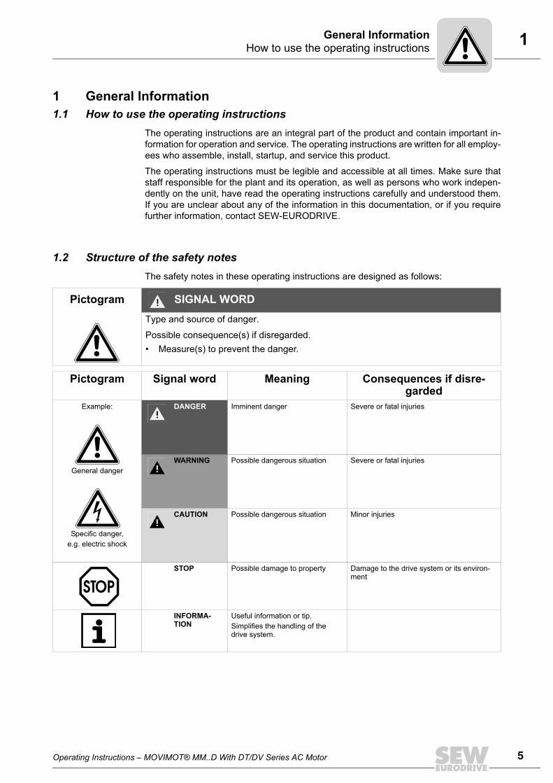
1.2 Structure of the safety notesThe safety notes in these operating instructions are designed as follows:
Pictogram SIGNAL WORDType and source of danger.
Possible consequence(s) if disregarded.• Measure(s) to prevent the danger.
Pictogram Signal word Meaning Consequences if disre-garded
Example:
General danger
Specific danger,e.g. electric shock
DANGER Imminent danger Severe or fatal injuries
WARNING Possible dangerous situation Severe or fatal injuries
CAUTION Possible dangerous situation Minor injuries
STOP Possible damage to property Damage to the drive system or its environ-ment
INFORMA-TION
Useful information or tip.Simplifies the handling of the drive system.
6 Operating Instructions – MOVIMOT® MM..D With DT/DV Series AC Motor
1 Right to claim under limited warrantyGeneral Information
1.3 Right to claim under limited warrantyA requirement of fault-free operation and fulfillment of any rights to claim under limitedwarranty is that you adhere to the information in the operating instructions. Therefore,read the operating instructions before you start working with the unit.
Make sure that the operating instructions are available to persons responsible for theplant and its operation, as well as to person who work independently on the unit. Youmust also ensure that the documentation is legible.
1.4 Exclusion of liabilityYou must comply with the information contained in these operating instructions to en-sure safe operation of the MOVIMOT® MM..D inverter and to achieve the specified prod-uct characteristics and performance requirements. SEW-EURODRIVE does not as-sume liability for injury to persons or damage to equipment or property resulting fromnon-observance of these operating instructions. In such cases, any liability for defectsis excluded.
1.5 Copyright notice© 2009 – SEW-EURODRIVE. All rights reserved.
Unauthorized reproduction, copying, distribution or any other use of the whole or anypart of this documentation is strictly prohibited.
Operating Instructions – MOVIMOT® MM..D With DT/DV Series AC Motor 7
2General informationSafety Notes
2 Safety NotesThe following basic safety notes must be read carefully to prevent injury to persons anddamage to property. The operator must ensure that the basic safety notes are read andobserved. Make sure that persons responsible for the plant and its operation, as well aspersons who work independently on the unit, have read through the operating instruc-tions carefully and understood them. If you are unclear about any of the information inthis documentation, please contact SEW-EURODRIVE.
2.1 General informationNever install or start up damaged products. Submit a complaint to the shipping companyimmediately in the event of damage.
During operation, MOVIMOT® drives can have live, bare and movable or rotating partsas well as hot surfaces, depending on their enclosure.
Removing covers without authorization, improper use as well as incorrect installation oroperation may result in severe injuries to persons or damage to property. Refer to thedocumentation for additional information.
2.2 Target groupOnly qualified electricians are authorized to install, startup or service the units or cor-rect unit faults (observing IEC 60364 or CENELEC HD 384 or DIN VDE 0100 andIEC 60664 or DIN VDE 0110 as well as national accident prevention guidelines).
Qualified electricians in the context of these basic safety notes are persons familiar withinstallation, assembly, startup and operation of the product who possess the requiredqualifications.
Any activities regarding transportation, storage, operation, and disposal must be carriedout by persons who have been instructed appropriately.
2.3 Designated useMOVIMOT® inverters are components intended for installation in electrical systems ormachines.
In case of installation in machines, startup of the MOVIMOT® inverters (i.e. start of des-ignated operation) is prohibited until it is determined that the machine meets the require-ments stipulated in the EC Directive 98/37/EC (machine guideline).
Startup (i.e. the start of designated use) is only permitted under observance of the EMCdirective 2004/108/EC.
MOVIMOT® inverters comply with the regulations of the Low Voltage Directive 2006/95/EC. The standards given in the declaration of conformity are used for the MOVIMOT®
inverter.
You must observe the technical data and information on the connection requirementsas provided on the nameplate and in the documentation.
2.3.1 Safety functionsThe MOVIMOT® inverter may not perform safety functions unless these functions aredescribed and expressly permitted.
8 Operating Instructions – MOVIMOT® MM..D With DT/DV Series AC Motor
2 Other applicable documentationSafety Notes
2.3.2 Hoist applicationsMOVIMOT® inverters are suitable for hoist applications to a limited degree only, seesec. "Additional function 9" (see page 62).
MOVIMOT® inverters may not be used as a safety device in hoist applications.
2.4 Other applicable documentationNote also the following documentation:
• "DR/DV/DT/DTE/DVE AC Motors, CT/CV Asynchronous Servomotors" operating in-structions
2.5 Transportation, storageObserve the notes on transportation, storage and proper handling. Comply with the re-quirements for climatic conditions stated in section "Technical Data". Tighten installedeyebolts securely. They are designed for the weight of the MOVIMOT® drive. Do not at-tach any additional loads. Use suitable, sufficiently rated handling equipment (e.g. ropeguides) if required.
2.6 InstallationThe units must be installed and cooled according to the regulations and specificationsin the corresponding documentation.
Protect the MOVIMOT® inverters from improper strain.
The following applications are prohibited unless the unit is explicitly designed for suchuse:
• Use in potentially explosive atmospheres.
• Use in areas exposed to harmful oils, acids, gases, vapors, dust, radiation, etc.
• Use in non-stationary applications with strong mechanical oscillation and impactloads; see section "Technical Data".
Operating Instructions – MOVIMOT® MM..D With DT/DV Series AC Motor 9
2Electrical ConnectionSafety Notes
2.7 Electrical ConnectionObserve the applicable national accident prevention guidelines when working on liveMOVIMOT® drive inverters (e.g. BGV A3).
Perform electrical installation according to the pertinent regulations (e.g. cable crosssections, fusing, protective conductor connection). For any additional information, referto the applicable documentation.
You will find notes on EMC-compliant installation, such as shielding, grounding, ar-rangement of filters and routing of lines, in the documentation of the MOVIMOT® in-verter. The manufacturer of the system or machine is responsible for maintaining thelimits established by EMC legislation.
Protective measures and protection devices must comply with the regulations in force(e.g. EN 60204 or EN 61800-5-1).
A voltage test according to EN 61800-5-1:2007 chapter 5.2.3.2 is required for theMOVIMOT® drives prior to startup in order to ensure the insulation.
2.8 Safe disconnectionMOVIMOT® inverters meet all requirements for safe disconnection of power and elec-tronic connections in accordance with EN 61800-5-1. All connected circuits must alsosatisfy the requirements for safe disconnection.
2.9 OperationSystems with integrated MOVIMOT® inverters must be equipped with additional moni-toring and protection devices according to the applicable safety guidelines, such as thelaw governing technical equipment, accident prevention regulations, etc. Additional pro-tective measures may be necessary for applications with increased potential risk.Changes to the MOVIMOT® inverter using the operating software are permitted.
Do not touch live components and power connections immediately after separation ofthe MOVIMOT® inverter from the supply voltage because there may still be somecharged capacitors. Wait at least for 1 minute after having switched off the supply volt-age.
As soon as supply voltages are present at the MOVIMOT® inverter, the terminal boxmust be closed (i.e. the MOVIMOT® inverter must be bolted on).
The fact that the status LED and other display elements are no longer illuminated doesnot indicate that the unit has been disconnected from the supply system and no longercarries any voltage.
Mechanical blocking or internal safety functions of the unit can cause a motor standstill.Eliminating the cause of the problem or performing a reset may result in the drive re-starting automatically. If, for safety reasons, this is not permitted for the driven machine,disconnect the unit from the supply system before correcting the error.
Caution: Danger of burns: The surface temperature of the MOVIMOT® drive and of ex-ternal options, e.g. the heat sink of the braking resistor, can exceed 60 °C during oper-ation!
10 Operating Instructions – MOVIMOT® MM..D With DT/DV Series AC Motor
3MOVIMOT® inverterUnit Structure
3 Unit Structure3.1 MOVIMOT® inverter
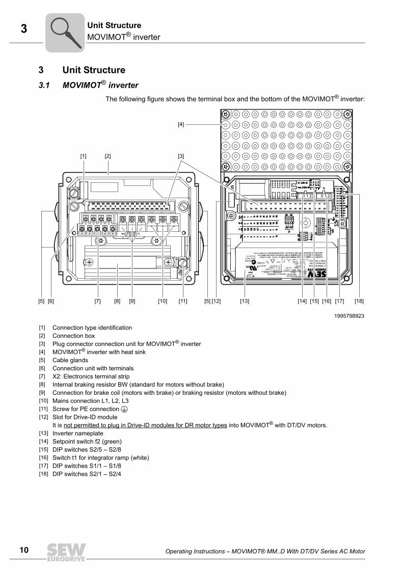
The following figure shows the terminal box and the bottom of the MOVIMOT® inverter:
1995798923
[1] Connection type identification[2] Connection box[3] Plug connector connection unit for MOVIMOT® inverter[4] MOVIMOT® inverter with heat sink[5] Cable glands [6] Connection unit with terminals[7] X2: Electronics terminal strip [8] Internal braking resistor BW (standard for motors without brake)[9] Connection for brake coil (motors with brake) or braking resistor (motors without brake)[10] Mains connection L1, L2, L3[11] Screw for PE connection [12] Slot for Drive-ID module
It is not permitted to plug in Drive-ID modules for DR motor types into MOVIMOT® with DT/DV motors.[13] Inverter nameplate[14] Setpoint switch f2 (green)[15] DIP switches S2/5 – S2/8[16] Switch t1 for integrator ramp (white)[17] DIP switches S1/1 – S1/8[18] DIP switches S2/1 – S2/4
[6][5] [11] [13] [15]
0 1 2 0 1 2
[14] [16][5] [12] [17] [18][7] [8] [9] [10]
[4]
[3][1] [2]
Operating Instructions – MOVIMOT® MM..D With DT/DV Series AC Motor 11
3MOVIMOT® inverter
Unit Structure
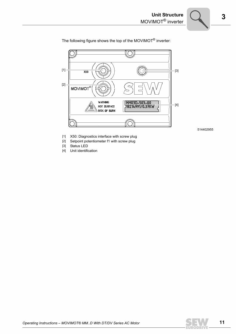
The following figure shows the top of the MOVIMOT® inverter:
514402955
[1] X50: Diagnostics interface with screw plug[2] Setpoint potentiometer f1 with screw plug[3] Status LED[4] Unit identification
[4]
[3]
[2]
[1]
12 Operating Instructions – MOVIMOT® MM..D With DT/DV Series AC Motor
3 Unit designationsUnit Structure
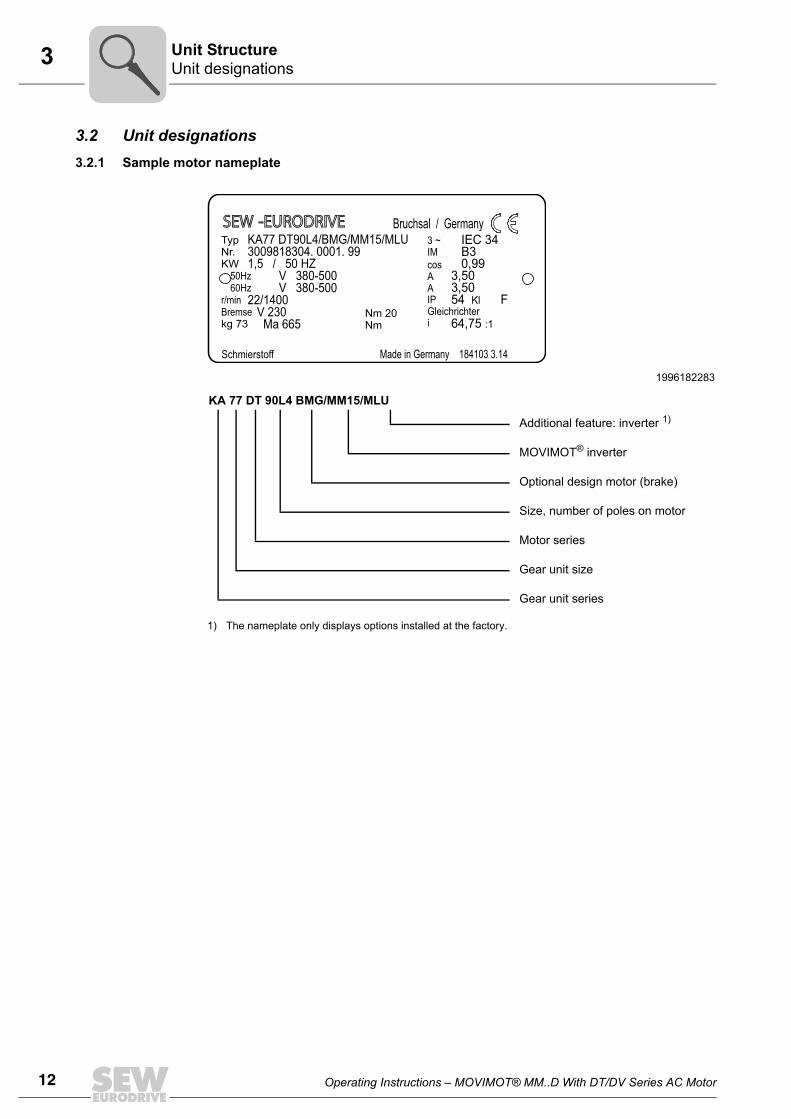
3.2 Unit designations3.2.1 Sample motor nameplate
1996182283
KA 77 DT 90L4 BMG/MM15/MLU
Additional feature: inverter 1)
1) The nameplate only displays options installed at the factory.
MOVIMOT® inverter
Optional design motor (brake)
Size, number of poles on motor
Motor series
Gear unit size
Gear unit series
SEW -EURODRIVESEW -EURODRIVETypNr.KW
kg 73
50Hz60Hz
r/minBremse
KA77 DT90L4/BMG/MM15/MLU3009818304. 0001. 991,5 / 50 HZ
V 380-500V 380-500
22/1400V 230Ma 665
IEC 34B30,99
3,503,5054 F
64,75
Kl
:1
Schmierstoff
Bruchsal / Germany3 ~IMcosAAIPGleichrichteri
Nm 20Nm
Made in Germany 184103 3.14
Operating Instructions – MOVIMOT® MM..D With DT/DV Series AC Motor 13
3Unit designationsUnit Structure
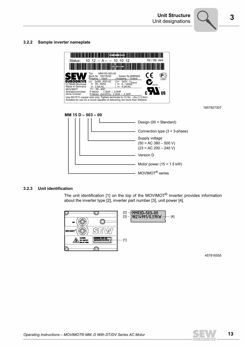
3.2.2 Sample inverter nameplate
3.2.3 Unit identificationThe unit identification [1] on the top of the MOVIMOT® inverter provides informationabout the inverter type [2], inverter part number [3], unit power [4].
1957927307
MM 15 D – 503 – 00
Design (00 = Standard)
Connection type (3 = 3-phase)
Supply voltage(50 = AC 380 – 500 V)(23 = AC 200 – 240 V)
Version D
Motor power (15 = 1.5 kW)
MOVIMOT® series
Status: 10 12 -- A -- -- 10 10 12 02 / 08 444
Typ MM15D-503-00Sach.Nr. 18215033Eingang / InputU=
f=I=
T= -30...40CI=3.5A AC 4.0A ACf=50...60HzD-76646 Bruchsal
MOVIMOTAntriebsumrichter P-Motor
P-Motor (S3/25%): 2.2kW / 3.3HP1.5kW / 2.0HP
Drive InverterUse 60/75°C copper wire only. Tighten terminals to 13,3in. - ibs.(1.5 Nm)Suitable for use on a circuit capable of delivering not more than 5000ms
Made in Germany2...120Hz3x0V...UInputU=3x380...500V AC
Ausgang / OutputSerien Nr.0886946
CH01
N2936
457916555
[2]
[4][3]
[1]
14 Operating Instructions – MOVIMOT® MM..D With DT/DV Series AC Motor
3 Unit designationsUnit Structure
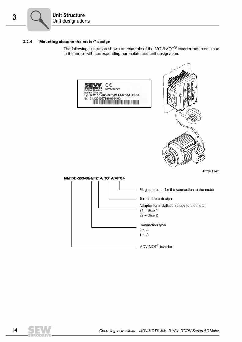
3.2.4 "Mounting close to the motor" design
The following illustration shows an example of the MOVIMOT® inverter mounted closeto the motor with corresponding nameplate and unit designation:
457921547
MM15D-503-00/0/P21A/RO1A/APG4
Plug connector for the connection to the motor
Terminal box design
Adapter for installation close to the motor21 = Size 122 = Size 2
Connection type0 = 1 =
MOVIMOT® inverter
MM15D-503-00/0/P21A/RO1A/APG4
Operating Instructions – MOVIMOT® MM..D With DT/DV Series AC Motor 15
4MOVIMOT® gearmotor
Mechanical Installation
4 Mechanical Installation4.1 MOVIMOT® gearmotor4.1.1 Before you start
Only install the MOVIMOT® drive if:
• The entries on the nameplate of the drive match the voltage supply system.
• the drive is undamaged (no damage caused by transportation or storage).
• you are certain that the following requirements have been fulfilled:
– Ambient temperature corresponds to the specifications in section "TechnicalData". Note that the temperature range of the gear unit may also be restricted(see gear unit operating instructions).
– No oil, acid, gas, vapors, radiation, etc.
Installation tolerances
The following tables shows the permitted tolerances of the shaft ends and flanges of theMOVIMOT® drive.
shaft end Flanges
Diameter tolerance according to EN 50347• ISO j6 with Ø ≤ 26 mm• ISO k6 with Ø ≤ 38 mm up to ≤ 48 mm • ISO m6 at Ø > 55 mm• Center bore in accordance with DIN 332, shape
DR..
Centering shoulder tolerance in accordance with EN 50347• ISO j6 with Ø ≤ 250 mm• ISO h6 with Ø > 300 mm
16 Operating Instructions – MOVIMOT® MM..D With DT/DV Series AC Motor
4MOVIMOT® gearmotorMechanical Installation
4.1.2 Installing MOVIMOT®
Observe the following notes for mounting the MOVIMOT® drive:
• Install/mount the MOVIMOT® drive only in the mounting position specified on themotor nameplate on a level, vibration-free, and torsionally rigid support structure.
• Clean the output shafts thoroughly to ensure they are free of anti-corrosion agents(use a commercially available solvent). Do not allow the solvent to penetrate thebearings and shaft seals – this could damage the material.
• Carefully align the MOVIMOT® inverter and the motor, to avoid placing anyunacceptable strain on the motor shafts (observe permissible overhung load andaxial load data!).
• Do not butt or hammer the shaft end.
• Use an appropriate cover to prevent objects or fluids from entering motors in verticalmounting positions.
• Ensure there is sufficient clearance around the unit to allow for adequate cooling.Furthermore, the unit must be positioned in such a way that it does not reuse the airwarmed by other devices.
• Balance components for subsequent mounting on the shaft with a half key (outputshafts are balanced with a half key).
• Existing condensation drain holes must be sealed with plastic plugs. They must notbe opened unless needed.
• Open condensation drain holes are not permitted. If condensation drain holes areopen, higher enclosures are no longer possible.
4.1.3 installation in damp locations or in the openObserve the following notes for mounting the MOVIMOT® drive in damp areas or in theopen:
• Use suitable cable glands for the supply leads (use reducing adapters if necessary).
• Coat the threads of cable glands and filler plugs with sealing compound and tightenthem well; then coat them again.
• Seal the cable entries well.
• Clean the sealing faces of the MOVIMOT® inverter well before re-assembly.
• If the corrosion protection coating is damaged, restore the coating.
• Check enclosure according to nameplate.
STOPThe degree of protection specified in the technical data only applies if the MOVIMOT®
inverter is properly installed.
When the MOVIMOT® inverter is removed from the connection box, it might be dam-aged by humidity or dust.• Protect the MOVIMOT® inverter when it is removed from the connection box.
Operating Instructions – MOVIMOT® MM..D With DT/DV Series AC Motor 17
4MLU11A / MLU21A / MLG..A optionMechanical Installation
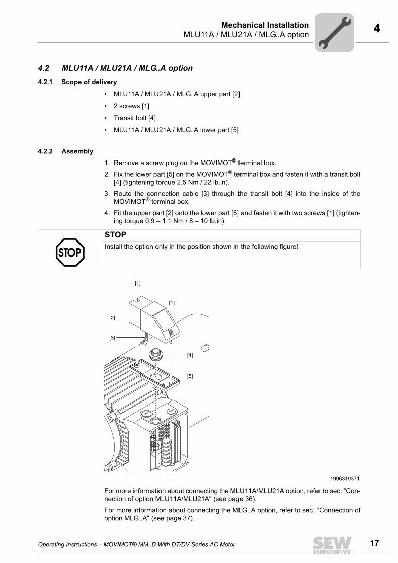
4.2 MLU11A / MLU21A / MLG..A option 4.2.1 Scope of delivery
• MLU11A / MLU21A / MLG..A upper part [2]
• 2 screws [1]
• Transit bolt [4]
• MLU11A / MLU21A / MLG..A lower part [5]
4.2.2 Assembly1. Remove a screw plug on the MOVIMOT® terminal box.
2. Fix the lower part [5] on the MOVIMOT® terminal box and fasten it with a transit bolt[4] (tightening torque 2.5 Nm / 22 lb.in).
3. Route the connection cable [3] through the transit bolt [4] into the inside of theMOVIMOT® terminal box.
4. Fit the upper part [2] onto the lower part [5] and fasten it with two screws [1] (tighten-ing torque 0.9 – 1.1 Nm / 8 – 10 lb.in).
For more information about connecting the MLU11A/MLU21A option, refer to sec. "Con-nection of option MLU11A/MLU21A" (see page 36).
For more information about connecting the MLG..A option, refer to sec. "Connection ofoption MLG..A" (see page 37).
STOPInstall the option only in the position shown in the following figure!
1996319371
[1]
[2]
[3]
[4]
[5]
[1]
18 Operating Instructions – MOVIMOT® MM..D With DT/DV Series AC Motor
4 MLU13A optionMechanical Installation
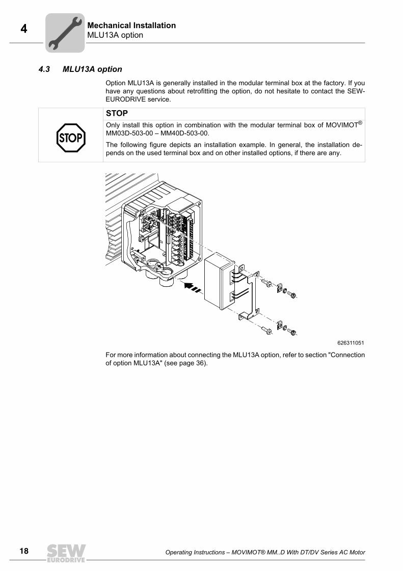
4.3 MLU13A optionOption MLU13A is generally installed in the modular terminal box at the factory. If youhave any questions about retrofitting the option, do not hesitate to contact the SEW-EURODRIVE service.
For more information about connecting the MLU13A option, refer to section "Connectionof option MLU13A" (see page 36).
STOPOnly install this option in combination with the modular terminal box of MOVIMOT®
MM03D-503-00 – MM40D-503-00.
The following figure depicts an installation example. In general, the installation de-pends on the used terminal box and on other installed options, if there are any.
626311051
Operating Instructions – MOVIMOT® MM..D With DT/DV Series AC Motor 19
4URM/BGM optionMechanical Installation
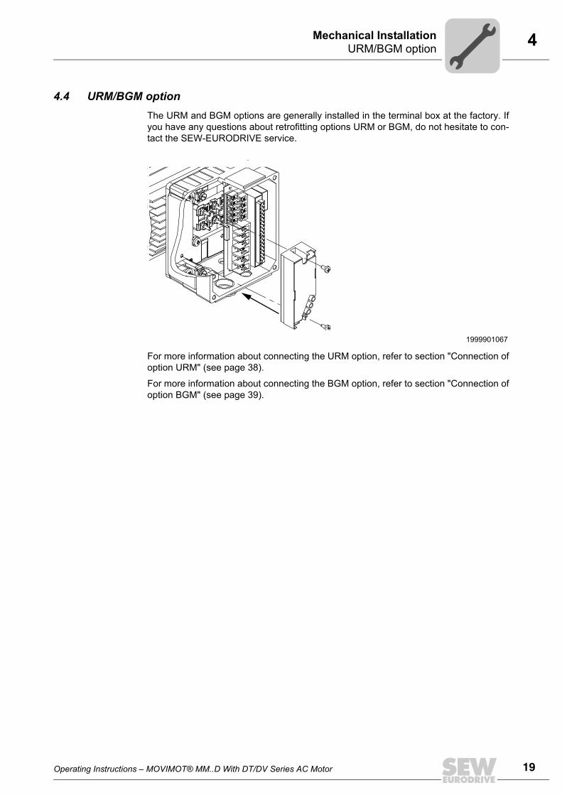
4.4 URM/BGM optionThe URM and BGM options are generally installed in the terminal box at the factory. Ifyou have any questions about retrofitting options URM or BGM, do not hesitate to con-tact the SEW-EURODRIVE service.
For more information about connecting the URM option, refer to section "Connection ofoption URM" (see page 38).
For more information about connecting the BGM option, refer to section "Connection ofoption BGM" (see page 39).
1999901067
20 Operating Instructions – MOVIMOT® MM..D With DT/DV Series AC Motor
4 Installation MBG11AMechanical Installation
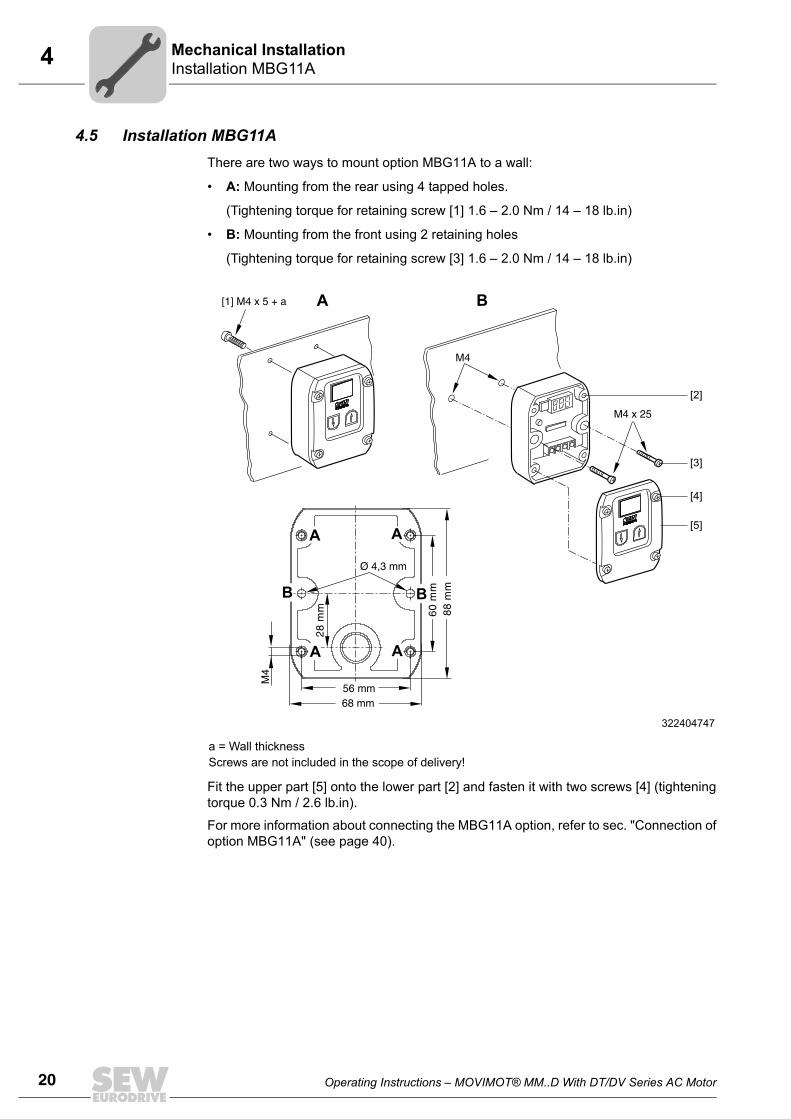
4.5 Installation MBG11AThere are two ways to mount option MBG11A to a wall:
• A: Mounting from the rear using 4 tapped holes.
(Tightening torque for retaining screw [1] 1.6 – 2.0 Nm / 14 – 18 lb.in)
• B: Mounting from the front using 2 retaining holes
(Tightening torque for retaining screw [3] 1.6 – 2.0 Nm / 14 – 18 lb.in)
Fit the upper part [5] onto the lower part [2] and fasten it with two screws [4] (tighteningtorque 0.3 Nm / 2.6 lb.in).
For more information about connecting the MBG11A option, refer to sec. "Connection ofoption MBG11A" (see page 40).
322404747
a = Wall thicknessScrews are not included in the scope of delivery!
A B2
M4
8 m
m
68 mm56 mm
Ø 4,3 mm
M4
[1] M4 x 5 + a
M4 x 25
60 m
m8
8 m
m
A A
A A
B B
[3]
[2]
[4]
[5]
Operating Instructions – MOVIMOT® MM..D With DT/DV Series AC Motor 21
4MWA21A optionMechanical Installation
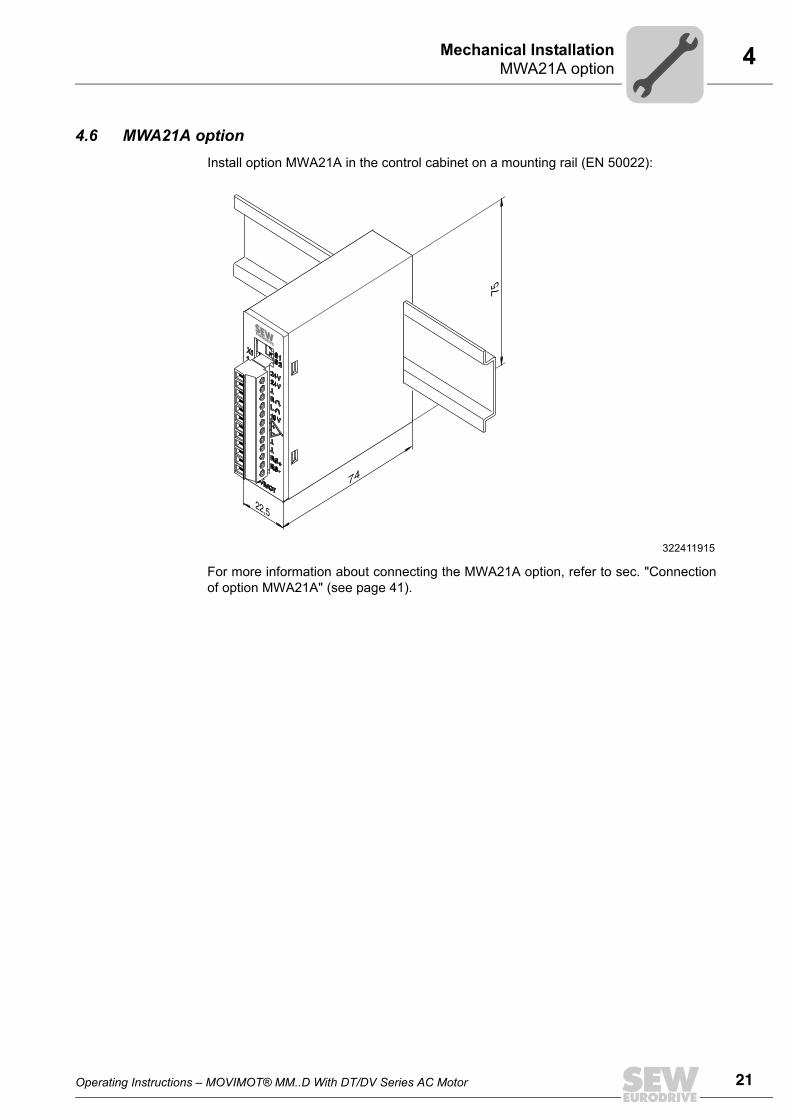
4.6 MWA21A optionInstall option MWA21A in the control cabinet on a mounting rail (EN 50022):
For more information about connecting the MWA21A option, refer to sec. "Connectionof option MWA21A" (see page 41).
322411915
22,5
74
75
22 Operating Instructions – MOVIMOT® MM..D With DT/DV Series AC Motor
4Installing the MOVIMOT® inverter close to the motorMechanical Installation
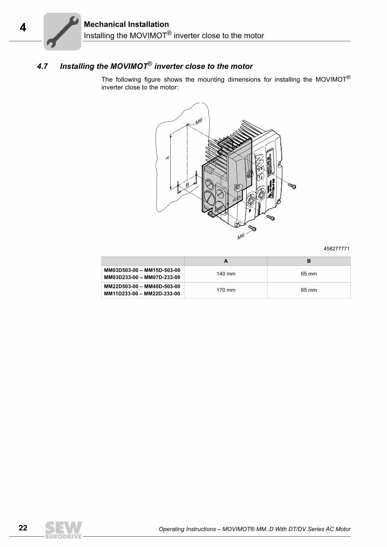
4.7 Installing the MOVIMOT® inverter close to the motorThe following figure shows the mounting dimensions for installing the MOVIMOT®
inverter close to the motor:
458277771
A B
MM03D503-00 – MM15D-503-00MM03D233-00 – MM07D-233-00 140 mm 65 mm
MM22D503-00 – MM40D-503-00MM11D233-00 – MM22D-233-00 170 mm 65 mm
A
B
M6
M6
Operating Instructions – MOVIMOT® MM..D With DT/DV Series AC Motor 23
4Tightening torquesMechanical Installation
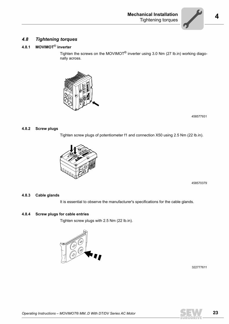
4.8 Tightening torques4.8.1 MOVIMOT® inverter
Tighten the screws on the MOVIMOT® inverter using 3.0 Nm (27 lb.in) working diago-nally across.
4.8.2 Screw plugsTighten screw plugs of potentiometer f1 and connection X50 using 2.5 Nm (22 lb.in).
4.8.3 Cable glandsIt is essential to observe the manufacturer's specifications for the cable glands.
4.8.4 Screw plugs for cable entriesTighten screw plugs with 2.5 Nm (22 lb.in).
458577931
458570379
322777611
24 Operating Instructions – MOVIMOT® MM..D With DT/DV Series AC Motor
4 Tightening torquesMechanical Installation
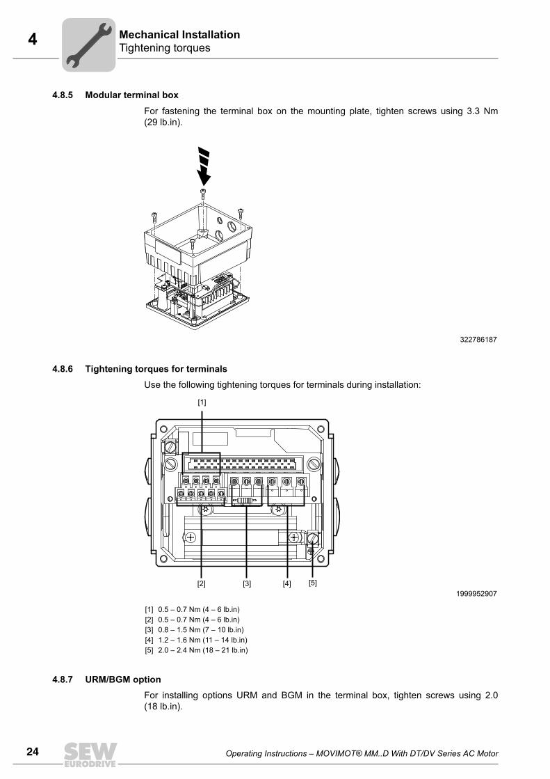
4.8.5 Modular terminal box
For fastening the terminal box on the mounting plate, tighten screws using 3.3 Nm(29 lb.in).
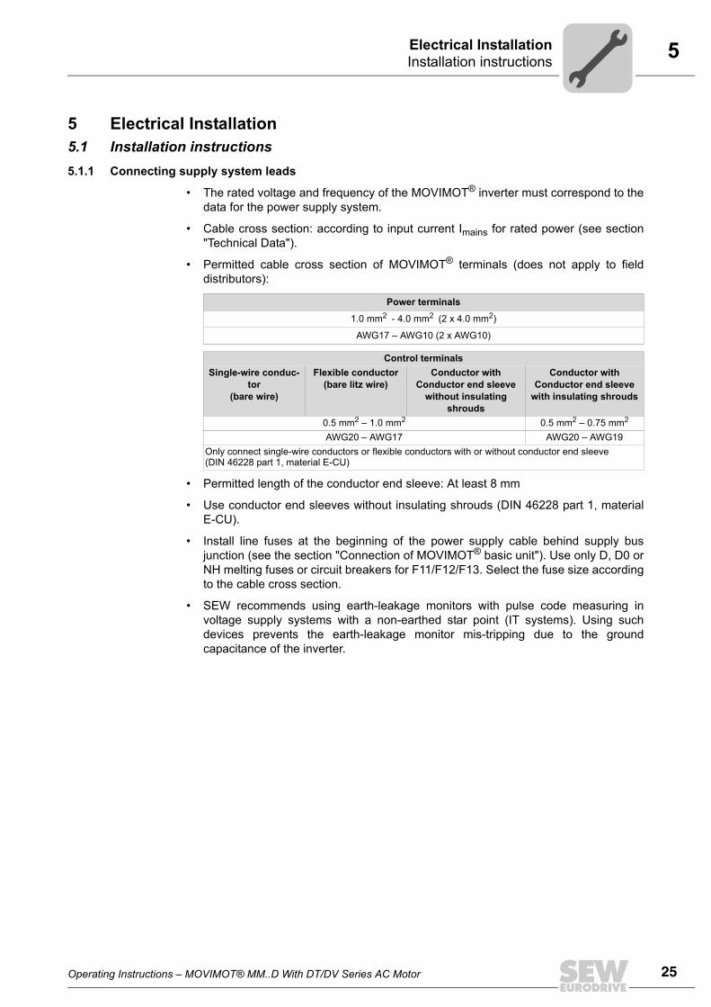
4.8.6 Tightening torques for terminalsUse the following tightening torques for terminals during installation:
4.8.7 URM/BGM optionFor installing options URM and BGM in the terminal box, tighten screws using 2.0(18 lb.in).
322786187
1999952907
[1][2] [3] [4] [5]
0.5 – 0.7 Nm (4 – 6 lb.in)0.5 – 0.7 Nm (4 – 6 lb.in)0.8 – 1.5 Nm (7 – 10 lb.in)1.2 – 1.6 Nm (11 – 14 lb.in)2.0 – 2.4 Nm (18 – 21 lb.in)
[1]
[5][2] [3] [4]
Operating Instructions – MOVIMOT® MM..D With DT/DV Series AC Motor 25
5Installation instructionsElectrical Installation
5 Electrical Installation5.1 Installation instructions5.1.1 Connecting supply system leads
• The rated voltage and frequency of the MOVIMOT® inverter must correspond to thedata for the power supply system.
• Cable cross section: according to input current Imains for rated power (see section"Technical Data").
• Permitted cable cross section of MOVIMOT® terminals (does not apply to fielddistributors):
• Permitted length of the conductor end sleeve: At least 8 mm
• Use conductor end sleeves without insulating shrouds (DIN 46228 part 1, materialE-CU).
• Install line fuses at the beginning of the power supply cable behind supply busjunction (see the section "Connection of MOVIMOT® basic unit"). Use only D, D0 orNH melting fuses or circuit breakers for F11/F12/F13. Select the fuse size accordingto the cable cross section.
• SEW recommends using earth-leakage monitors with pulse code measuring involtage supply systems with a non-earthed star point (IT systems). Using suchdevices prevents the earth-leakage monitor mis-tripping due to the groundcapacitance of the inverter.
Power terminals
1.0 mm2 - 4.0 mm2 (2 x 4.0 mm2)
AWG17 – AWG10 (2 x AWG10)
Control terminalsSingle-wire conduc-
tor(bare wire)
Flexible conductor (bare litz wire)
Conductor with Conductor end sleeve
without insulating shrouds
Conductor with Conductor end sleeve
with insulating shrouds
0.5 mm2 – 1.0 mm2 0.5 mm2 – 0.75 mm2
AWG20 – AWG17 AWG20 – AWG19Only connect single-wire conductors or flexible conductors with or without conductor end sleeve (DIN 46228 part 1, material E-CU)
26 Operating Instructions – MOVIMOT® MM..D With DT/DV Series AC Motor
5 Installation instructionsElectrical Installation
5.1.2 Earth-leakage circuit breakers
• Do not use a conventional earth-leakage circuit breaker as a protective device.Universal current-sensitive earth leakage circuit-breakers (tripping current 300 mA)are permitted as a protective device. During normal operation of MOVIMOT®
inverter, earth-leakage currents of > 3.5 mA can occur.
• SEW-EURODRIVE recommends that you do not use earth-leakage circuit breakers.However, if an earth-leakage circuit breaker is stipulated for direct or indirect protec-tion against contact, observe the following note in accordance with EN 61800-5-1:
5.1.3 Input contactor
• Only use a contactor of utilization category AC3 (EN 60947-4-1) as an inputcontactor.
WARNINGWrong type of earth-leakage circuit breaker installed.
Severe or fatal injuries.
MOVIMOT® can cause direct current in the protective earth. In cases where an earth-leakage circuit breaker is used for protection against direct or indirect contact, only in-stall a type B earth-leakage circuit breaker on the power supply end of the MOVIMOT®
inverter.
STOP• Do not use the K11 input contactor (see wiring diagram (see page 30)) for jog
mode, but only for switching the inverter on and off. For jog mode, use the the com-mands "CW / Stop" or "CCW / Stop".
• Observe a minimum switch-off time of 2 s for the supply system contactor K11.
Operating Instructions – MOVIMOT® MM..D With DT/DV Series AC Motor 27
5Installation instructionsElectrical Installation
5.1.4 Notes on PE connection
Earth-leakage currents ≥ 3.5 mA may occur during normal operation. To meet the re-quirements of EN 61800-5-1 observe the following note:
• Route a second PE conductor with the cross section of the supply system lead inparallel to the protective earth via separate terminals or use a copper protective earthconductor with a cross section of 10 mm2.
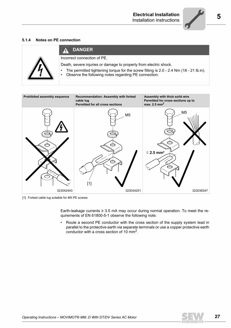
DANGERIncorrect connection of PE.
Death, severe injuries or damage to property from electric shock.• The permitted tightening torque for the screw fitting is 2.0 - 2.4 Nm (18 - 21 lb.in).• Observe the following notes regarding PE connection.
Prohibited assembly sequence Recommendation: Assembly with forked cable lugPermitted for all cross sections
Assembly with thick solid wirePermitted for cross sections up to max. 2.5 mm2
323042443 323034251 323038347
[1] Forked cable lug suitable for M5 PE screws
[1]
M5
2.5 mm²
M5
28 Operating Instructions – MOVIMOT® MM..D With DT/DV Series AC Motor
5 Installation instructionsElectrical Installation
5.1.5 EMC-compliant installation
With respect to the EMC regulation, frequency inverters cannot be operated as stand-alone units. Regarding EMC, they can only be evaluated when they are integrated in adrive system. Conformity is declared for a described, CE-typical drive system. These op-erating instructions contain further information.
5.1.6 Installation altitude above 1000 m above sea levelMOVIMOT® drives with supply voltages of 200 to 240 V or 380 to 500 V can be used ataltitudes above 1,000 msl up to 4,000 msl under the following conditions1) .
• The rated continuous power is reduced based on the reduced cooling above 1000 m(see section "Technical Data").
• Above 2,000 msl, the air and creeping distances are only sufficient for overvoltageclass 2. If the installation calls for overvoltage class 3, you will have to installadditional external overvoltage protection to limit overvoltage peaks to 2.5 kV phase-to-phase and phase-to-ground.
• If safe electrical disconnection is required, it must be implemented outside the deviceat altitudes of 2,000 msl (safe electrical disconnection in accordance with EN 61800-5-1).
• In installation altitudes between 2,000 m to 4,000 msl, the permitted rated powersupply voltages are reduced as follows:
– By 6 V per 100 m for MM..D-503-00
– By 3 V per 100 m for MM..D-233-00
5.1.7 Connecting 24 V supply
• Power the MOVIMOT® inverter either via an external 24 V supply or the MLU..A orMLG..A options.
5.1.8 Binary control
• Connect the required control leads.
• Use shielded cables as control cables and route them separately from supply systemcables.
WARNINGThis drive system is not designed for operation on a public low voltage supply systemthat supplies residential areas.
INFORMATION• This is a product with restricted availability in accordance with IEC 61800-3. It may
cause EMC interference. In this case, it may be recommended for the operator to carry out suitable measures.
• For detailed information on EMC compliant installation, refer to the publication "Electromagnetic Compatibility in Drive Engineering" from SEW-EURODRIVE.
1) The maximum altitude is limited by creeping distances and flameproof components such as electrolyticcapacitors.
Operating Instructions – MOVIMOT® MM..D With DT/DV Series AC Motor 29
5Installation instructionsElectrical Installation
5.1.9 Control via RS-485 interface
The MOVIMOT® drive is controlled via the RS-485 interface by one of the following con-trollers:
• MOVIFIT®-MC
• Fieldbus interfaces MF../MQ..
• PLC bus master
• MLG..A option
• MBG11A option
• MWA21A option
• Use twisted pair shielded cables as control leads and route them separately fromsupply system leads.
5.1.10 Protection devices
• MOVIMOT® drives are equipped with integrated protection devices against overload.External overload devices are not necessary.
5.1.11 UL-compliant installation
• Use only copper cables for temperature range 60/75 °C as connection lead.
• The permitted tightening torques for MOVIMOT® power terminals are: 1.5 Nm(13 lb.in).
• The permitted supply system voltage is 500 V (400/500 V inverter) or 240 V (230 Vinverter). Information about the max. permitted short-circuit currents of the supplysystem and the fuse is listed on the nameplate of the MOVIMOT® inverter.
INFORMATIONOnly ever connect one bus master.
INFORMATION• Only use certified units with a limited output voltage (Umax = DC 30 V) and limited
power (P ≤ 100 VA) as an external DC 24 V voltage source.• The UL certification only applies for the operation on voltage supply systems with
voltages to ground of max. 300 V. The UL-certification does not apply for the operation on voltage supply systems with a non-grounded star point (IT systems).
30 Operating Instructions – MOVIMOT® MM..D With DT/DV Series AC Motor
5Connection of MOVIMOT®Electrical Installation
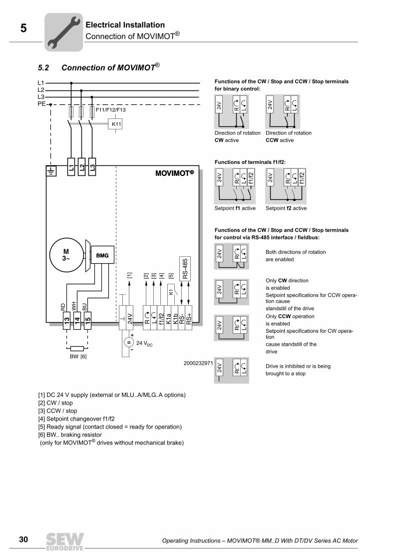
5.2 Connection of MOVIMOT®
2000232971
Functions of the CW / Stop and CCW / Stop terminalsfor binary control:
Direction of rotation CW active
Direction of rotation CCW active
Functions of terminals f1/f2:
Setpoint f1 active Setpoint f2 active
Functions of the CW / Stop and CCW / Stop terminalsfor control via RS-485 interface / fieldbus:
Both directions of rotation are enabled
Only CW directionis enabled Setpoint specifications for CCW opera-tion causestandstill of the driveOnly CCW operationis enabled Setpoint specifications for CW opera-tion cause standstill of thedrive
Drive is inhibited or is being brought to a stop
[1] DC 24 V supply (external or MLU..A/MLG..A options)[2] CW / stop[3] CCW / stop[4] Setpoint changeover f1/f2[5] Ready signal (contact closed = ready for operation)[6] BW.. braking resistor (only for MOVIMOT® drives without mechanical brake)
M3~
L1L2L3PE
K11
F11/F12/F13
K1
RS
-485
13 14 15
L1
L2
L3
24V
R L f1/f2
K1a
K1b
RS
-R
S+
=+
-
BMG
MOVIMOT®
RD
WH
BMG
MOVIMOT®
[1]
[2]
[3]
[4]
[5]
24 VDC
BU
BW [6]
R L24V
R L24V
R L24V
f1/f2
R L24V
f1/f2
24V
R L
24V
R L
24V
R L
24V
R L
Operating Instructions – MOVIMOT® MM..D With DT/DV Series AC Motor 31
5MOVIMOT ® plug connectors
Electrical Installation
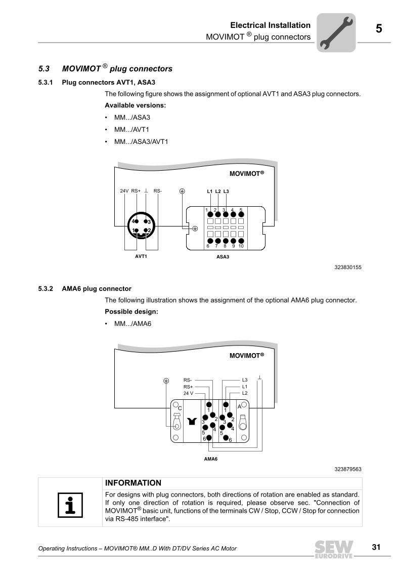
5.3 MOVIMOT ® plug connectors5.3.1 Plug connectors AVT1, ASA3
The following figure shows the assignment of optional AVT1 and ASA3 plug connectors.
Available versions:
• MM.../ASA3
• MM.../AVT1
• MM.../ASA3/AVT1
5.3.2 AMA6 plug connectorThe following illustration shows the assignment of the optional AMA6 plug connector.
Possible design:
• MM.../AMA6
323830155
1 2 3 4 5
6 7 8 9
1 2
4 3
MOVIMOT®
L1 L2 L324V RS+ RS-
ASA3AVT1
10
323879563
MOVIMOT®
AMA6
1
23
456
1
2
AC
3
45
6
24 V
RS+
RS-
L2
L1
L3
INFORMATIONFor designs with plug connectors, both directions of rotation are enabled as standard.If only one direction of rotation is required, please observe sec. "Connection ofMOVIMOT® basic unit, functions of the terminals CW / Stop, CCW / Stop for connectionvia RS-485 interface".
32 Operating Instructions – MOVIMOT® MM..D With DT/DV Series AC Motor
5MOVIMOT®/motor connection – Mounting close to the motorElectrical Installation
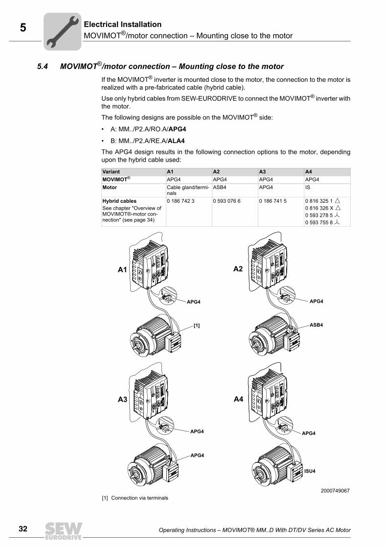
5.4 MOVIMOT®/motor connection – Mounting close to the motorIf the MOVIMOT® inverter is mounted close to the motor, the connection to the motor isrealized with a pre-fabricated cable (hybrid cable).
Use only hybrid cables from SEW-EURODRIVE to connect the MOVIMOT® inverter withthe motor.
The following designs are possible on the MOVIMOT® side:
• A: MM../P2.A/RO.A/APG4
• B: MM../P2.A/RE.A/ALA4The APG4 design results in the following connection options to the motor, dependingupon the hybrid cable used:
Variant A1 A2 A3 A4MOVIMOT® APG4 APG4 APG4 APG4Motor Cable gland/termi-
nalsASB4 APG4 IS
Hybrid cablesSee chapter "Overview of MOVIMOT®-motor con-nection" (see page 34)
0 186 742 3 0 593 076 6 0 186 741 5 0 816 325 1 0 816 326 X 0 593 278 5 0 593 755 8
2000749067[1] Connection via terminals
A2
A3
ASB4
APG4
APG4
APG4
APG4
ISU4
A4
A1
APG4
[1]
Operating Instructions – MOVIMOT® MM..D With DT/DV Series AC Motor 33
5MOVIMOT®/motor connection – Mounting close to the motor
Electrical Installation
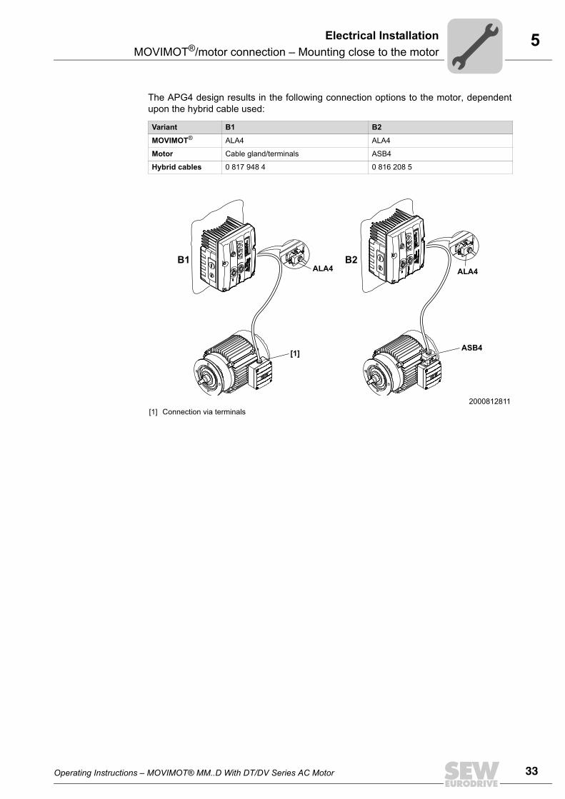
The APG4 design results in the following connection options to the motor, dependentupon the hybrid cable used:
Variant B1 B2
MOVIMOT® ALA4 ALA4
Motor Cable gland/terminals ASB4
Hybrid cables 0 817 948 4 0 816 208 5
2000812811[1] Connection via terminals
B1 B2
ASB4[1]
ALA4 ALA4
34 Operating Instructions – MOVIMOT® MM..D With DT/DV Series AC Motor
5MOVIMOT®/motor connection – Mounting close to the motorElectrical Installation
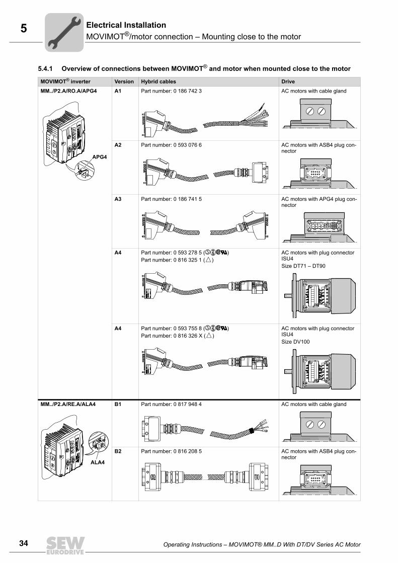
5.4.1 Overview of connections between MOVIMOT® and motor when mounted close to the motor
MOVIMOT® inverter Version Hybrid cables Drive
MM../P2.A/RO.A/APG4 A1 Part number: 0 186 742 3 AC motors with cable gland
A2 Part number: 0 593 076 6 AC motors with ASB4 plug con-nector
A3 Part number: 0 186 741 5 AC motors with APG4 plug con-nector
A4 Part number: 0 593 278 5 ()Part number: 0 816 325 1 ()
AC motors with plug connector ISU4 Size DT71 – DT90
A4 Part number: 0 593 755 8 ()Part number: 0 816 326 X ()
AC motors with plug connector ISU4Size DV100
MM../P2.A/RE.A/ALA4 B1 Part number: 0 817 948 4 AC motors with cable gland
B2 Part number: 0 816 208 5 AC motors with ASB4 plug con-nector
APG4
Auftr
agsn
umm
er:
Auftr
agsn
umm
er:
R 01/
00R 0
1/00
Laen
ge (m
):La
enge
(m):
593 2
78 5
593 2
78 5
Auftr
agsn
umm
er:
Auftr
agsn
umm
er:
R 01/
00R 0
1/00
Laen
ge (m
):La
enge
(m):
593 2
78 5
593 2
78 5
ALA4
Operating Instructions – MOVIMOT® MM..D With DT/DV Series AC Motor 35
5MOVIMOT®/motor connection – Mounting close to the motor
Electrical Installation
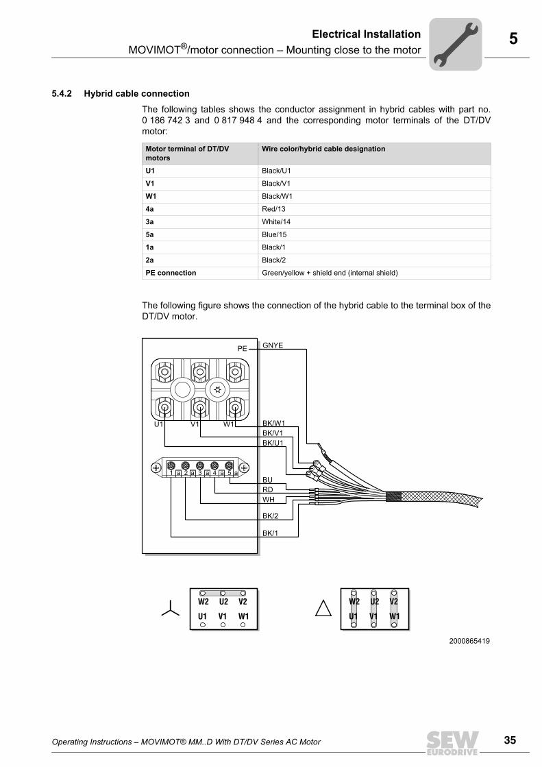
5.4.2 Hybrid cable connection
The following tables shows the conductor assignment in hybrid cables with part no.0 186 742 3 and 0 817 948 4 and the corresponding motor terminals of the DT/DVmotor:
The following figure shows the connection of the hybrid cable to the terminal box of theDT/DV motor.
Motor terminal of DT/DV motors
Wire color/hybrid cable designation
U1 Black/U1
V1 Black/V1
W1 Black/W1
4a Red/13
3a White/14
5a Blue/15
1a Black/1
2a Black/2
PE connection Green/yellow + shield end (internal shield)
2000865419
1
BK/1
BK/2
BURDWH
a a a a a2 3 4 5
BK/W1U1 V1 W1
GNYEPE
BK/V1BK/U1
U1 V1 W1
W2 U2 V2
U1 V1 W1
W2 U2 V2
36 Operating Instructions – MOVIMOT® MM..D With DT/DV Series AC Motor
5Connecting the MOVIMOT® optionsElectrical Installation
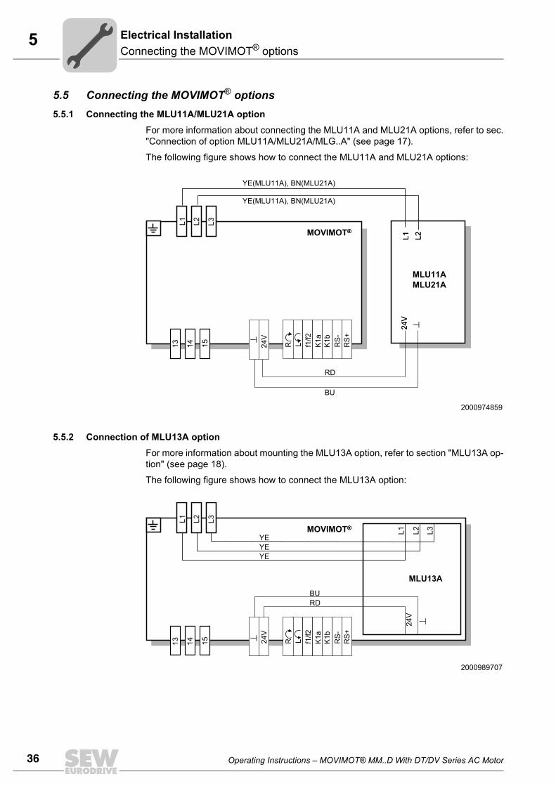
5.5 Connecting the MOVIMOT® options 5.5.1 Connecting the MLU11A/MLU21A option
For more information about connecting the MLU11A and MLU21A options, refer to sec."Connection of option MLU11A/MLU21A/MLG..A" (see page 17).
The following figure shows how to connect the MLU11A and MLU21A options:
5.5.2 Connection of MLU13A optionFor more information about mounting the MLU13A option, refer to section "MLU13A op-tion" (see page 18).
The following figure shows how to connect the MLU13A option:
2000974859L1 L2
24V
MOVIMOT®
YE(MLU11A), BN(MLU21A)
YE(MLU11A), BN(MLU21A)
RD
BUL1 L2
24V
MLU11A MLU21A
®
13 14 15 24V
R L f1/f2
K1a
K1b
RS-
RS+
L1 L2 L3
2000989707
MOVIMOT® L1 L2 L3
24V
MLU13A
®
YEYEYE
RDBU
L1 L2 L3
13 14 15 24V
R L f1/f2
K1a
K1b
RS-
RS+
Operating Instructions – MOVIMOT® MM..D With DT/DV Series AC Motor 37
5Connecting the MOVIMOT® options
Electrical Installation
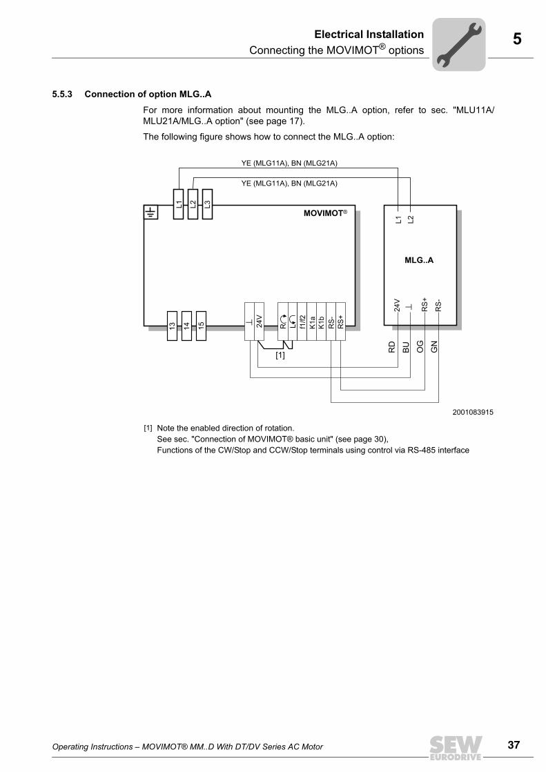
5.5.3 Connection of option MLG..A
For more information about mounting the MLG..A option, refer to sec. "MLU11A/MLU21A/MLG..A option" (see page 17).
The following figure shows how to connect the MLG..A option:
2001083915
[1] Note the enabled direction of rotation. See sec. "Connection of MOVIMOT® basic unit" (see page 30),Functions of the CW/Stop and CCW/Stop terminals using control via RS-485 interface
RD
BU OG
GN
YE (MLG11A), BN (MLG21A)
YE (MLG11A), BN (MLG21A)
MOVIMOT®
L1 L2
24V
RS
+
RS
-
MLG..A
[1]
13 14 15 24V
R L f1/f2
K1a
K1b
RS-
RS+
L1 L2 L3
38 Operating Instructions – MOVIMOT® MM..D With DT/DV Series AC Motor
5Connecting the MOVIMOT® optionsElectrical Installation
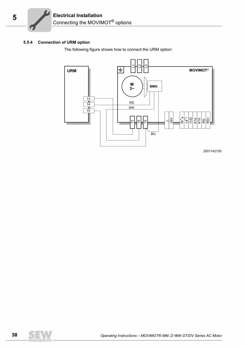
5.5.4 Connection of URM option
The following figure shows how to connect the URM option:
2001142155
M3~
RD
BMG
URM
13
14
15WH
BU
MOVIMOT®
13 14 15 24V
R L f1/f2
K1a
K1b
RS-
RS+
L1 L2 L3
Operating Instructions – MOVIMOT® MM..D With DT/DV Series AC Motor 39
5Connecting the MOVIMOT® options
Electrical Installation
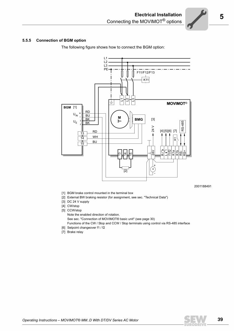
5.5.5 Connection of BGM option
The following figure shows how to connect the BGM option:
2001188491
[1][2][3][4][5]
[6][7]
BGM brake control mounted in the terminal box External BW braking resistor (for assignment, see sec. "Technical Data")DC 24 V supplyCW/stop CCW/stop Note the enabled direction of rotation.See sec. "Connection of MOVIMOT® basic unit" (see page 30) Functions of the CW / Stop and CCW / Stop terminals using control via RS-485 interfaceSetpoint changeover f1 / f2Brake relay
M3~
L1L2L3PE
K11
F11/F12/F13
K1
RS
-485
13
RD
RD
BKBK
WHBU
BU
14 15L3
24V
R L f1/f2
K1a
K1b
RS-
RS+
=+
-
MOVIMOT
+~
~
[1]
[2]
[3]
[4] [5][6] [7]
BMG
BGMMOVIMOT
24
V
1314
15
L1 L2
_
UIN
UE
40 Operating Instructions – MOVIMOT® MM..D With DT/DV Series AC Motor
5Connecting the MOVIMOT® optionsElectrical Installation
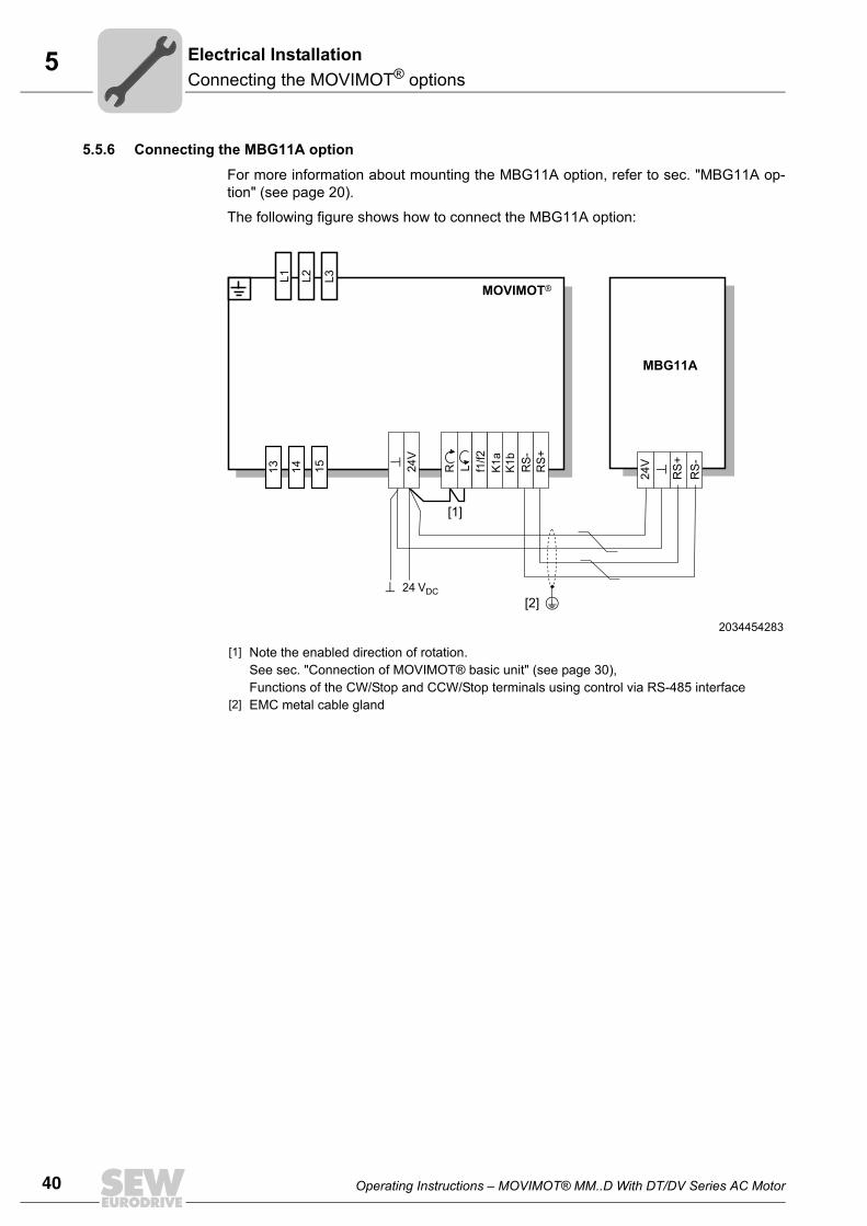
5.5.6 Connecting the MBG11A option
For more information about mounting the MBG11A option, refer to sec. "MBG11A op-tion" (see page 20).
The following figure shows how to connect the MBG11A option:
2034454283
[1] Note the enabled direction of rotation.See sec. "Connection of MOVIMOT® basic unit" (see page 30),Functions of the CW/Stop and CCW/Stop terminals using control via RS-485 interface
[2] EMC metal cable gland
MBG11A
24V
RS
+R
S-
MOVIMOT®
24 VDC[2]
[1]
13 14 15 24V
R L f1/f2
K1a
K1b
RS-
RS+
L1 L2 L3
Operating Instructions – MOVIMOT® MM..D With DT/DV Series AC Motor 41
5Connecting the MOVIMOT® options
Electrical Installation
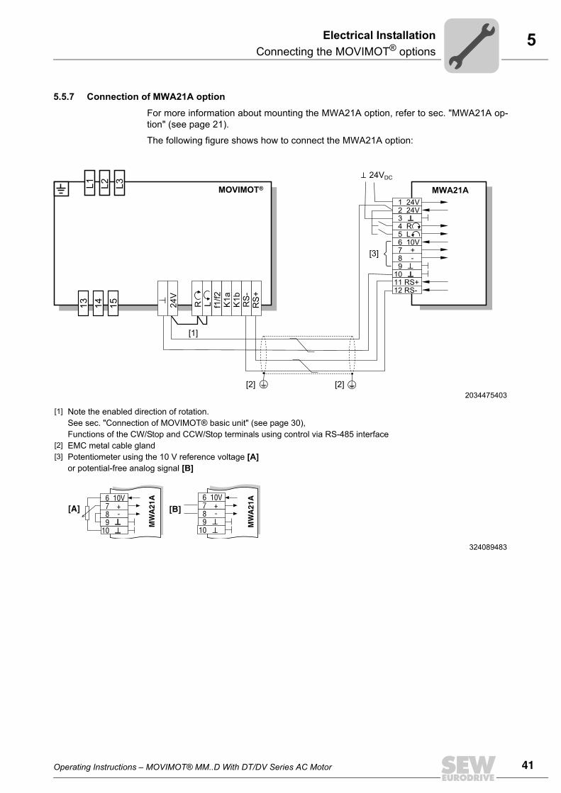
5.5.7 Connection of MWA21A option
For more information about mounting the MWA21A option, refer to sec. "MWA21A op-tion" (see page 21).
The following figure shows how to connect the MWA21A option:
2034475403
[1] Note the enabled direction of rotation. See sec. "Connection of MOVIMOT® basic unit" (see page 30), Functions of the CW/Stop and CCW/Stop terminals using control via RS-485 interface
[2] EMC metal cable gland[3] Potentiometer using the 10 V reference voltage [A]
or potential-free analog signal [B]
324089483
MWA21A1 24V2 24V34 R5 L6 10V7 +8 -9
1011 RS+12 RS-
24VDC
13 14 15
L1 L2 L3
24V
R L f1/f2
K1a
K1b RS
-R
S+
MOVIMOT®
[1]
[2][2]
[3]
6 10V7 +8 -9
10
6 10V7 +8 -9
10
MW
A21
A
MW
A21
A
[A] [B]
42 Operating Instructions – MOVIMOT® MM..D With DT/DV Series AC Motor
5 Connection of RS-485 bus masterElectrical Installation
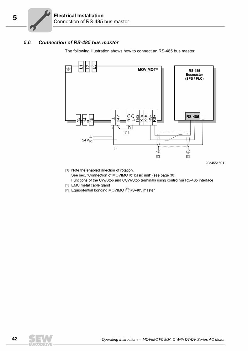
5.6 Connection of RS-485 bus masterThe following illustration shows how to connect an RS-485 bus master:
2034551691
[1] Note the enabled direction of rotation.See sec. "Connection of MOVIMOT® basic unit" (see page 30),Functions of the CW/Stop and CCW/Stop terminals using control via RS-485 interface
[2] EMC metal cable gland[3] Equipotential bonding MOVIMOT®/RS-485 master
RS-485
RS-485Busmaster(SPS / PLC)
13 14 15
L1 L2 L3
24V
R L f1/f2
K1a
K1b RS
-R
S+
MOVIMOT®
24 VDC
[1]
[3]
[2][2]
Operating Instructions – MOVIMOT® MM..D With DT/DV Series AC Motor 43
6Important notes on startupStartup
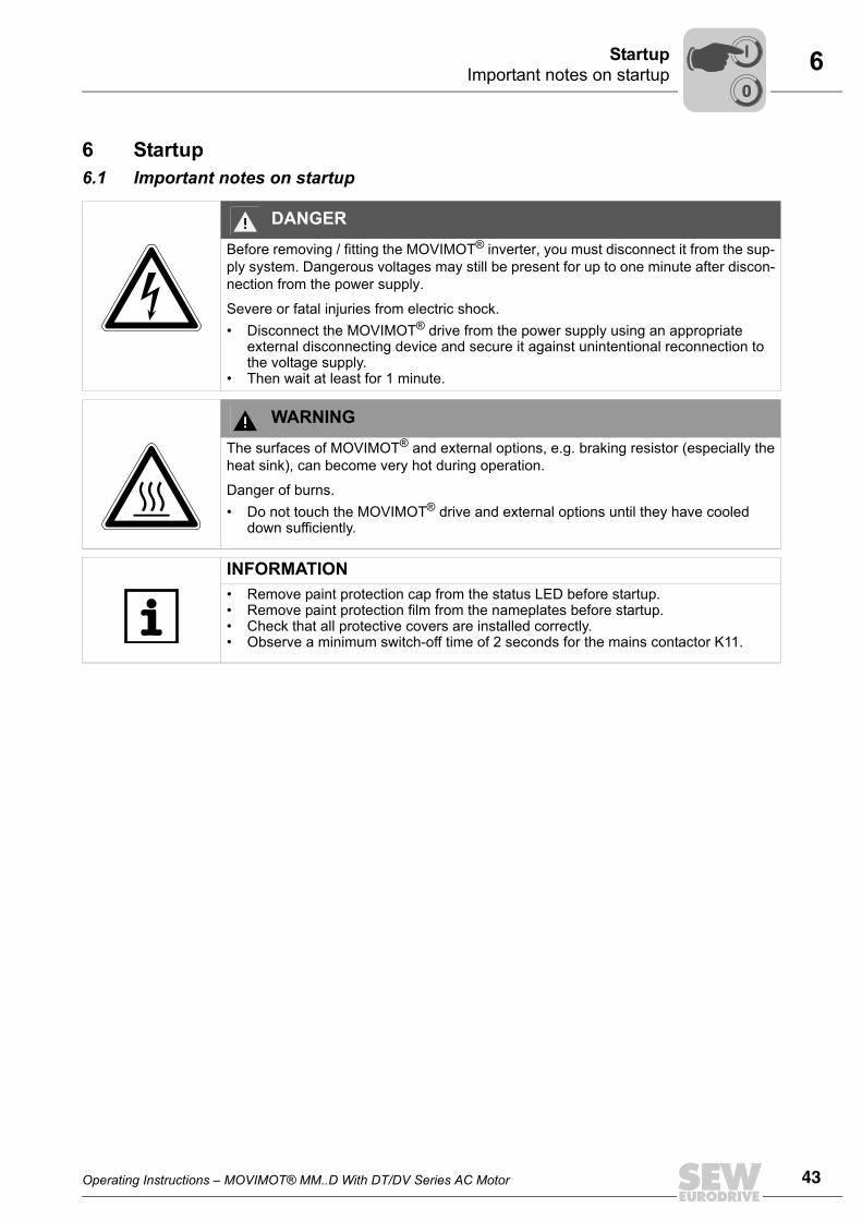
6 Startup6.1 Important notes on startup
DANGERBefore removing / fitting the MOVIMOT® inverter, you must disconnect it from the sup-ply system. Dangerous voltages may still be present for up to one minute after discon-nection from the power supply.
Severe or fatal injuries from electric shock.• Disconnect the MOVIMOT® drive from the power supply using an appropriate
external disconnecting device and secure it against unintentional reconnection to the voltage supply.
• Then wait at least for 1 minute.
WARNINGThe surfaces of MOVIMOT® and external options, e.g. braking resistor (especially theheat sink), can become very hot during operation.
Danger of burns.• Do not touch the MOVIMOT® drive and external options until they have cooled
down sufficiently.
INFORMATION• Remove paint protection cap from the status LED before startup.• Remove paint protection film from the nameplates before startup.• Check that all protective covers are installed correctly.• Observe a minimum switch-off time of 2 seconds for the mains contactor K11.
00
I
44 Operating Instructions – MOVIMOT® MM..D With DT/DV Series AC Motor
6 Description of the controlsStartup
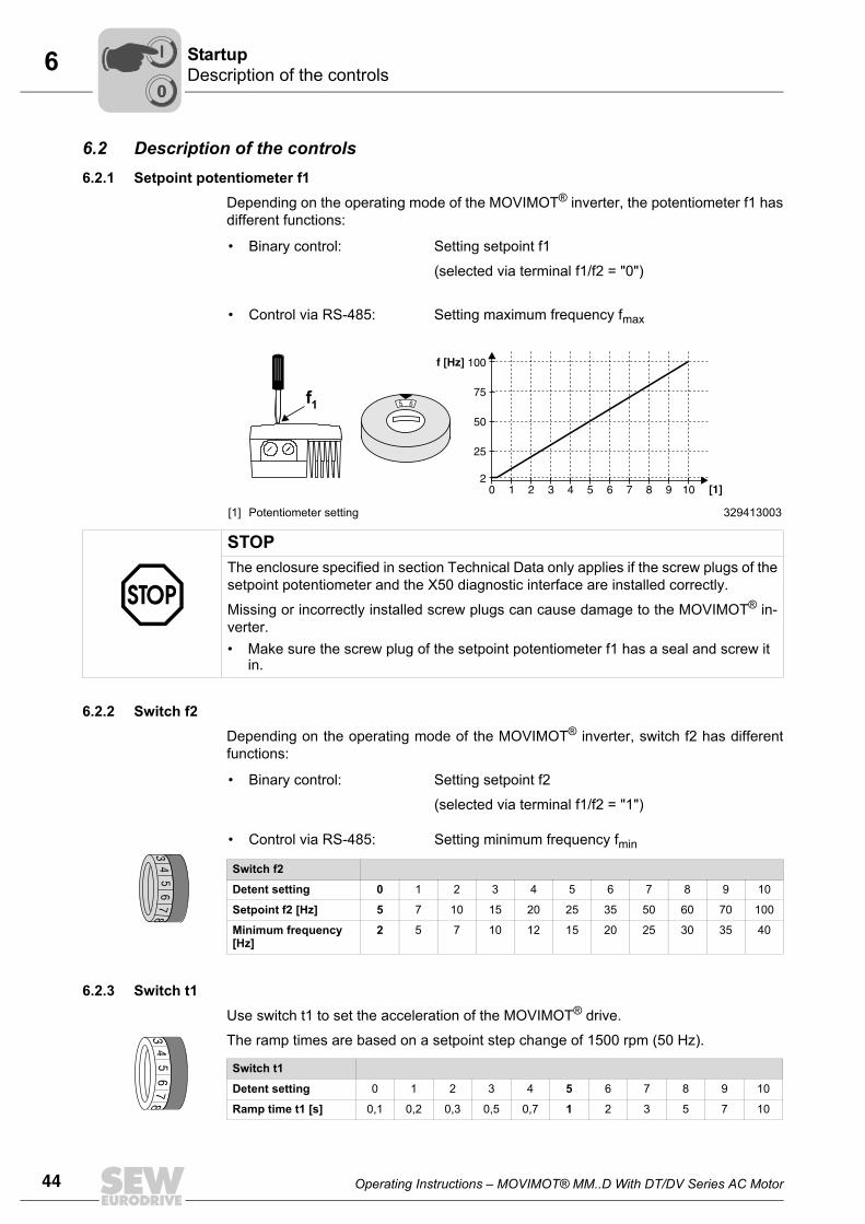
6.2 Description of the controls6.2.1 Setpoint potentiometer f1
Depending on the operating mode of the MOVIMOT® inverter, the potentiometer f1 hasdifferent functions:
6.2.2 Switch f2Depending on the operating mode of the MOVIMOT® inverter, switch f2 has differentfunctions:
6.2.3 Switch t1Use switch t1 to set the acceleration of the MOVIMOT® drive.
The ramp times are based on a setpoint step change of 1500 rpm (50 Hz).
• Binary control: Setting setpoint f1
(selected via terminal f1/f2 = "0")
• Control via RS-485: Setting maximum frequency fmax
[1] Potentiometer setting 329413003
1 2 3 4 5 6 7 8 9 100
100f [Hz
[1]
]
2
75
25
50
65f1
STOPThe enclosure specified in section Technical Data only applies if the screw plugs of thesetpoint potentiometer and the X50 diagnostic interface are installed correctly.
Missing or incorrectly installed screw plugs can cause damage to the MOVIMOT® in-verter.• Make sure the screw plug of the setpoint potentiometer f1 has a seal and screw it
in.
• Binary control: Setting setpoint f2
(selected via terminal f1/f2 = "1")
• Control via RS-485: Setting minimum frequency fmin
Switch f2
Detent setting 0 1 2 3 4 5 6 7 8 9 10
Setpoint f2 [Hz] 5 7 10 15 20 25 35 50 60 70 100
Minimum frequency [Hz]
2 5 7 10 12 15 20 25 30 35 40
34
56
78
Switch t1
Detent setting 0 1 2 3 4 5 6 7 8 9 10
Ramp time t1 [s] 0,1 0,2 0,3 0,5 0,7 1 2 3 5 7 10
34
56
78
00
I
Operating Instructions – MOVIMOT® MM..D With DT/DV Series AC Motor 45
6Description of the controlsStartup
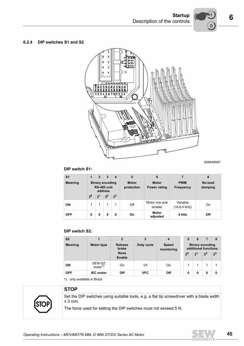
6.2.4 DIP switches S1 and S2
DIP switch S1:
DIP switch S2:
626648587
S1 1 2 3 4 5 6 7 8
Meaning Binary encodingRS-485 unit
address
Motorprotection
MotorPower rating
PWMFrequency
No-loaddamping
20 21 22 23
ON 1 1 1 1 OffMotor one size
smallerVariable
(16,8,4 kHz)On
OFF 0 0 0 0 On Motor adjusted 4 kHz Off
S2 1 2 3 4 5 6 7 8
Meaning Motor type Release brakeNone
Enable
Duty cycle Speedmonitoring
Binary encoding additional functions
20 21 22 23
ON SEW-DZ motor1)
1) only available in Brazil
On V/f On 1 1 1 1
OFF IEC motor Off VFC Off 0 0 0 0
STOPSet the DIP switches using suitable tools, e.g. a flat tip screwdriver with a blade width≤ 3 mm.
The force used for setting the DIP switches must not exceed 5 N.
00
I
46 Operating Instructions – MOVIMOT® MM..D With DT/DV Series AC Motor
6 Description of the DIP switches S1Startup
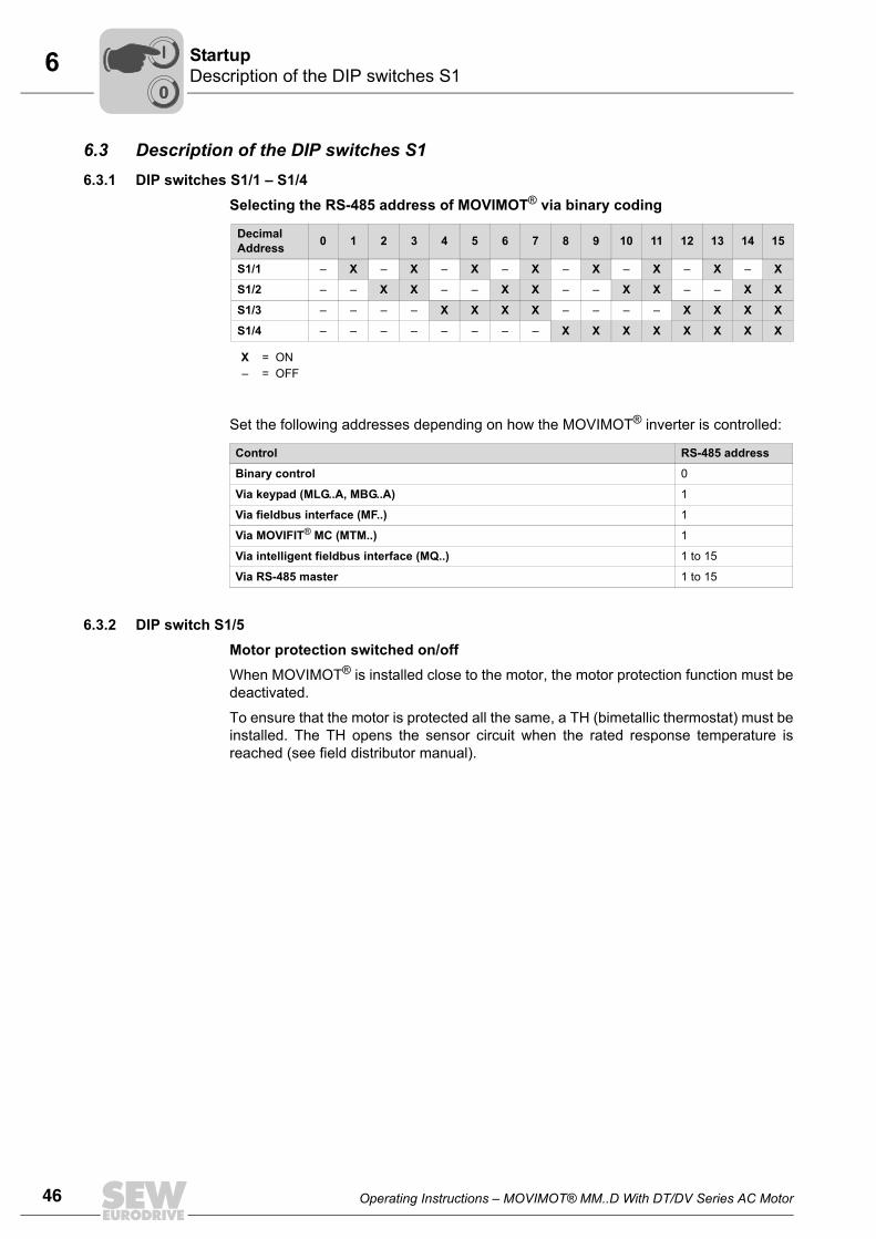
6.3 Description of the DIP switches S16.3.1 DIP switches S1/1 – S1/4
Selecting the RS-485 address of MOVIMOT® via binary coding
Set the following addresses depending on how the MOVIMOT® inverter is controlled:
6.3.2 DIP switch S1/5Motor protection switched on/offWhen MOVIMOT® is installed close to the motor, the motor protection function must bedeactivated.
To ensure that the motor is protected all the same, a TH (bimetallic thermostat) must beinstalled. The TH opens the sensor circuit when the rated response temperature isreached (see field distributor manual).
DecimalAddress 0 1 2 3 4 5 6 7 8 9 10 11 12 13 14 15
S1/1 – X – X – X – X – X – X – X – X
S1/2 – – X X – – X X – – X X – – X X
S1/3 – – – – X X X X – – – – X X X X
S1/4 – – – – – – – – X X X X X X X X
X = ON– = OFF
Control RS-485 address
Binary control 0
Via keypad (MLG..A, MBG..A) 1
Via fieldbus interface (MF..) 1
Via MOVIFIT® MC (MTM..) 1
Via intelligent fieldbus interface (MQ..) 1 to 15
Via RS-485 master 1 to 15
00
I
Operating Instructions – MOVIMOT® MM..D With DT/DV Series AC Motor 47
6Description of the DIP switches S1Startup
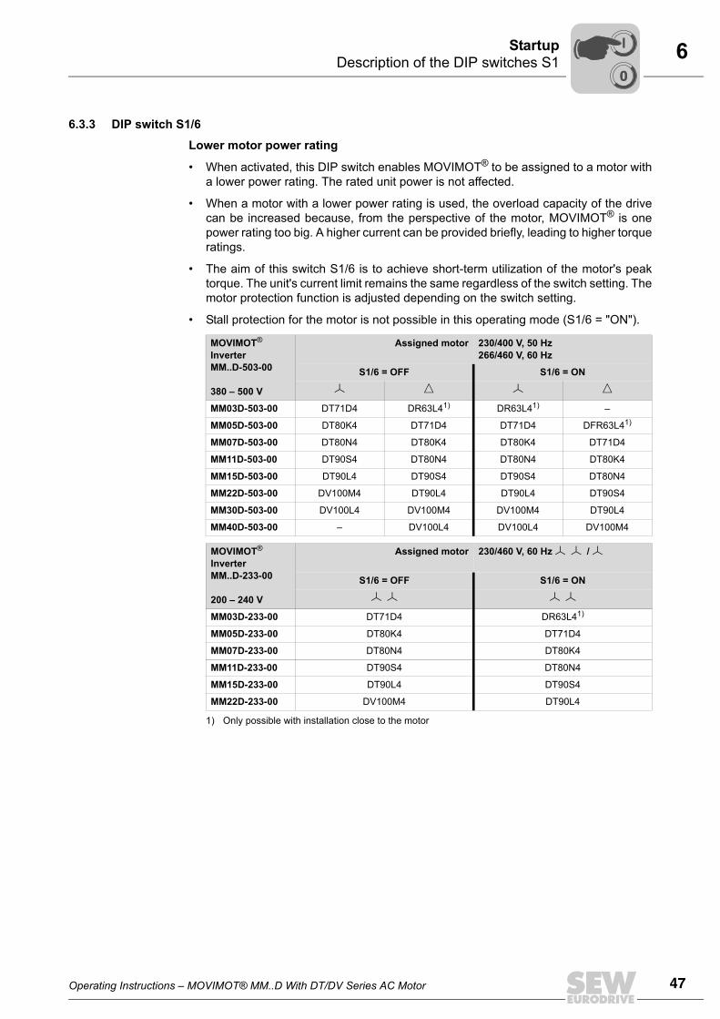
6.3.3 DIP switch S1/6
Lower motor power rating
• When activated, this DIP switch enables MOVIMOT® to be assigned to a motor witha lower power rating. The rated unit power is not affected.
• When a motor with a lower power rating is used, the overload capacity of the drivecan be increased because, from the perspective of the motor, MOVIMOT® is onepower rating too big. A higher current can be provided briefly, leading to higher torqueratings.
• The aim of this switch S1/6 is to achieve short-term utilization of the motor's peaktorque. The unit's current limit remains the same regardless of the switch setting. Themotor protection function is adjusted depending on the switch setting.
• Stall protection for the motor is not possible in this operating mode (S1/6 = "ON").
MOVIMOT® InverterMM..D-503-00
380 – 500 V
Assigned motor 230/400 V, 50 Hz266/460 V, 60 Hz
S1/6 = OFF S1/6 = ON
MM03D-503-00 DT71D4 DR63L41) DR63L41) –
MM05D-503-00 DT80K4 DT71D4 DT71D4 DFR63L41)
MM07D-503-00 DT80N4 DT80K4 DT80K4 DT71D4
MM11D-503-00 DT90S4 DT80N4 DT80N4 DT80K4
MM15D-503-00 DT90L4 DT90S4 DT90S4 DT80N4
MM22D-503-00 DV100M4 DT90L4 DT90L4 DT90S4
MM30D-503-00 DV100L4 DV100M4 DV100M4 DT90L4
MM40D-503-00 – DV100L4 DV100L4 DV100M4
MOVIMOT® InverterMM..D-233-00
200 – 240 V
Assigned motor 230/460 V, 60 Hz /
S1/6 = OFF S1/6 = ON
MM03D-233-00 DT71D4 DR63L41)
1) Only possible with installation close to the motor
MM05D-233-00 DT80K4 DT71D4
MM07D-233-00 DT80N4 DT80K4
MM11D-233-00 DT90S4 DT80N4
MM15D-233-00 DT90L4 DT90S4
MM22D-233-00 DV100M4 DT90L4
00
I
48 Operating Instructions – MOVIMOT® MM..D With DT/DV Series AC Motor
6 Description of DIP switches S2Startup
6.3.4 DIP switch S1/7
Setting the maximum PWM- frequency
• When DIP switch S1/7 is set to "OFF", the MOVIMOT® unit operates with 4 kHzPWM frequency.
• When DIP switch S1/7 is set to "ON", the MOVIMOT® unit operates with a 16 kHzPWM frequency (low noise) and switches back in steps to lower switching frequen-cies depending on the heat sink temperature and the inverter load.
6.3.5 DIP switch S1/8No load vibration damping (S1/8 = "ON")When setting DIP switch S1/8, this function reduces resonance during no-load opera-tion.
6.4 Description of DIP switches S26.4.1 DIP switch S2/1
Motor type
• For IEC and NEMA motors, DIP switch S2/1 must always be set to "OFF".
• For DZ motors with nominal voltages of 220/380 V, 60 Hz (only available in Brazil),the DIP switch must always be set to "ON".
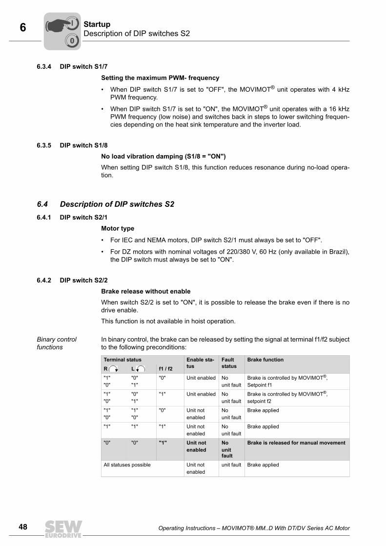
6.4.2 DIP switch S2/2Brake release without enableWhen switch S2/2 is set to "ON", it is possible to release the brake even if there is nodrive enable.
This function is not available in hoist operation.
Binary control functions
In binary control, the brake can be released by setting the signal at terminal f1/f2 subjectto the following preconditions:
Terminal status Enable sta-tus
Fault status
Brake function
R L f1 / f2
"1""0"
"0""1"
"0" Unit enabled No unit fault
Brake is controlled by MOVIMOT®, Setpoint f1
"1""0"
"0""1"
"1" Unit enabled No unit fault
Brake is controlled by MOVIMOT®, setpoint f2
"1""0"
"1""0"
"0" Unit not enabled
No unit fault
Brake applied
"1" "1" "1" Unit not enabled
No unit fault
Brake applied
"0" "0" "1" Unit not enabled
No unit fault
Brake is released for manual movement
All statuses possible Unit not enabled
unit fault Brake applied
00
I
Operating Instructions – MOVIMOT® MM..D With DT/DV Series AC Motor 49
6Description of DIP switches S2Startup
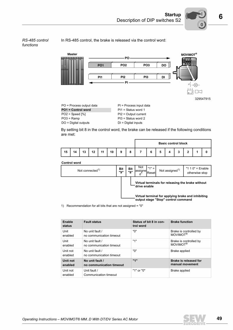
RS-485 control functions
In RS-485 control, the brake is released via the control word:
By setting bit 8 in the control word, the brake can be released if the following conditionsare met:
329547915
PO = Process output data PI = Process input dataPO1 = Control word PI1 = Status word 1PO2 = Speed [%] PI2 = Output currentPO3 = Ramp PI3 = Status word 2DO = Digital outputs DI = Digital inputs
Basic control block
15 14 13 12 11 10 9 8 7 6 5 4 3 2 1 0
Control word
Not connected1)
1) Recommendation for all bits that are not assigned = "0"
Bit "9"
Bit "8"
Not assigne
d1
"1" = Reset
Not assigned1) "1 1 0" = Enableotherwise stop
Virtual terminals for releasing the brake without drive enable
Virtual terminal for applying brake and inhibiting output stage "Stop" control command
Enablestatus
Fault status Status of bit 8 in con-trol word
Brake function
Unit enabled
No unit fault / no communication timeout
"0" Brake is controlled by MOVIMOT®
Unit enabled
No unit fault /no communication timeout
"1" Brake is controlled by MOVIMOT®
Unit notenabled
No unit fault / no communication timeout
"0" Brake applied
Unit not enabled
No unit fault / no communication timeout
"1" Brake is released for manual movement
Unit notenabled
Unit fault /Communication timeout
"1" or "0" Brake applied
MOVIMOT®
PO1 PO2 PO3 DO
Master
-+
PI1 PI2 PI3 DI
PO
PI
00
I
50 Operating Instructions – MOVIMOT® MM..D With DT/DV Series AC Motor
6 Description of DIP switches S2Startup
Setpoint selection for binary control
Setpoint selection in binary control depending on the status of terminal f1/f2:
Behavior if unit not ready
If the unit is not ready, the brake is always applied irrespective of the setting of terminalf1/f2 or bit 8 in the control word.
LED display The status LED flashes periodically at a fast rate (ton : toff = 100 ms : 300 ms) if the brakehas been released for manual movement. This applies both for binary control and forcontrol via RS-485.
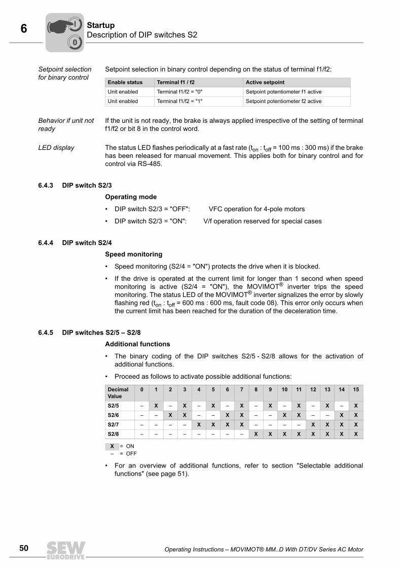
6.4.3 DIP switch S2/3Operating mode
• DIP switch S2/3 = "OFF": VFC operation for 4-pole motors
• DIP switch S2/3 = "ON": V/f operation reserved for special cases
6.4.4 DIP switch S2/4Speed monitoring
• Speed monitoring (S2/4 = "ON") protects the drive when it is blocked.
• If the drive is operated at the current limit for longer than 1 second when speedmonitoring is active (S2/4 = "ON"), the MOVIMOT® inverter trips the speedmonitoring. The status LED of the MOVIMOT® inverter signalizes the error by slowlyflashing red (ton : toff = 600 ms : 600 ms, fault code 08). This error only occurs whenthe current limit has been reached for the duration of the deceleration time.
6.4.5 DIP switches S2/5 – S2/8Additional functions
• The binary coding of the DIP switches S2/5 - S2/8 allows for the activation ofadditional functions.
• Proceed as follows to activate possible additional functions:
• For an overview of additional functions, refer to section "Selectable additionalfunctions" (see page 51).
Enable status Terminal f1 / f2 Active setpoint
Unit enabled Terminal f1/f2 = "0" Setpoint potentiometer f1 active
Unit enabled Terminal f1/f2 = "1" Setpoint potentiometer f2 active
DecimalValue
0 1 2 3 4 5 6 7 8 9 10 11 12 13 14 15
S2/5 – X – X – X – X – X – X – X – X
S2/6 – – X X – – X X – – X X – – X X
S2/7 – – – – X X X X – – – – X X X X
S2/8 – – – – – – – – X X X X X X X X
X = ON– = OFF
00
I
Operating Instructions – MOVIMOT® MM..D With DT/DV Series AC Motor 51
6Selectable additional functions of MM..D-503-00Startup
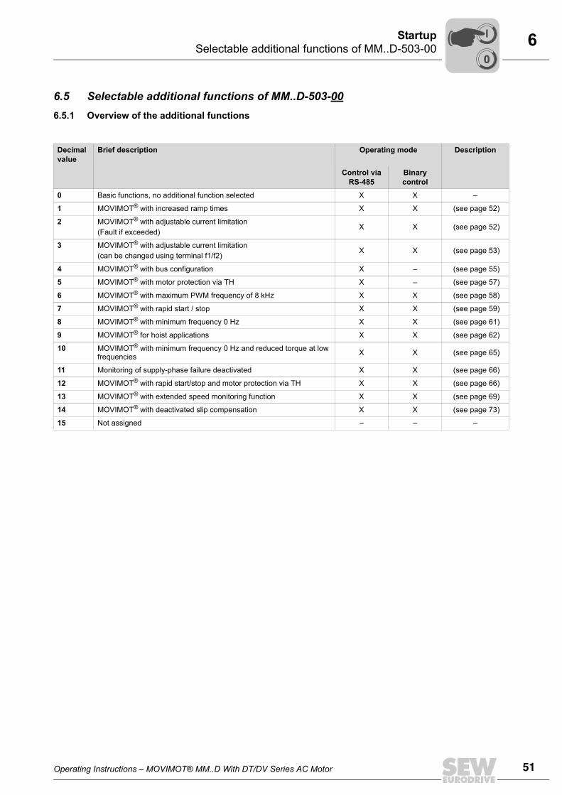
6.5 Selectable additional functions of MM..D-503-006.5.1 Overview of the additional functions
Decimalvalue
Brief description Operating mode Description
Control via RS-485
Binary control
0 Basic functions, no additional function selected X X –
1 MOVIMOT® with increased ramp times X X (see page 52)
2 MOVIMOT® with adjustable current limitation (Fault if exceeded)
X X (see page 52)
3 MOVIMOT® with adjustable current limitation (can be changed using terminal f1/f2)
X X (see page 53)
4 MOVIMOT® with bus configuration X – (see page 55)
5 MOVIMOT® with motor protection via TH X – (see page 57)
6 MOVIMOT® with maximum PWM frequency of 8 kHz X X (see page 58)
7 MOVIMOT® with rapid start / stop X X (see page 59)
8 MOVIMOT® with minimum frequency 0 Hz X X (see page 61)
9 MOVIMOT® for hoist applications X X (see page 62)
10 MOVIMOT® with minimum frequency 0 Hz and reduced torque at low frequencies X X (see page 65)
11 Monitoring of supply-phase failure deactivated X X (see page 66)
12 MOVIMOT® with rapid start/stop and motor protection via TH X X (see page 66)
13 MOVIMOT® with extended speed monitoring function X X (see page 69)
14 MOVIMOT® with deactivated slip compensation X X (see page 73)
15 Not assigned – – –
00
I
52 Operating Instructions – MOVIMOT® MM..D With DT/DV Series AC Motor
6 Selectable additional functions of MM..D-503-00Startup
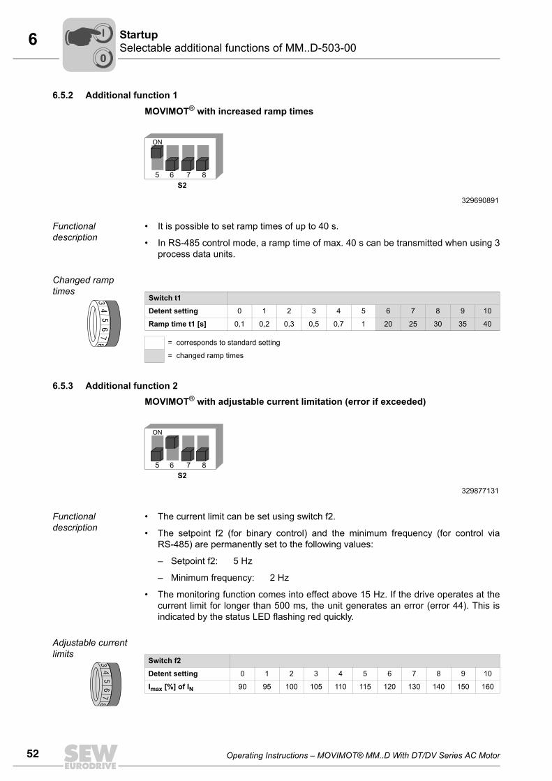
6.5.2 Additional function 1
MOVIMOT® with increased ramp times
Functional description
• It is possible to set ramp times of up to 40 s.
• In RS-485 control mode, a ramp time of max. 40 s can be transmitted when using 3process data units.
Changed ramp times
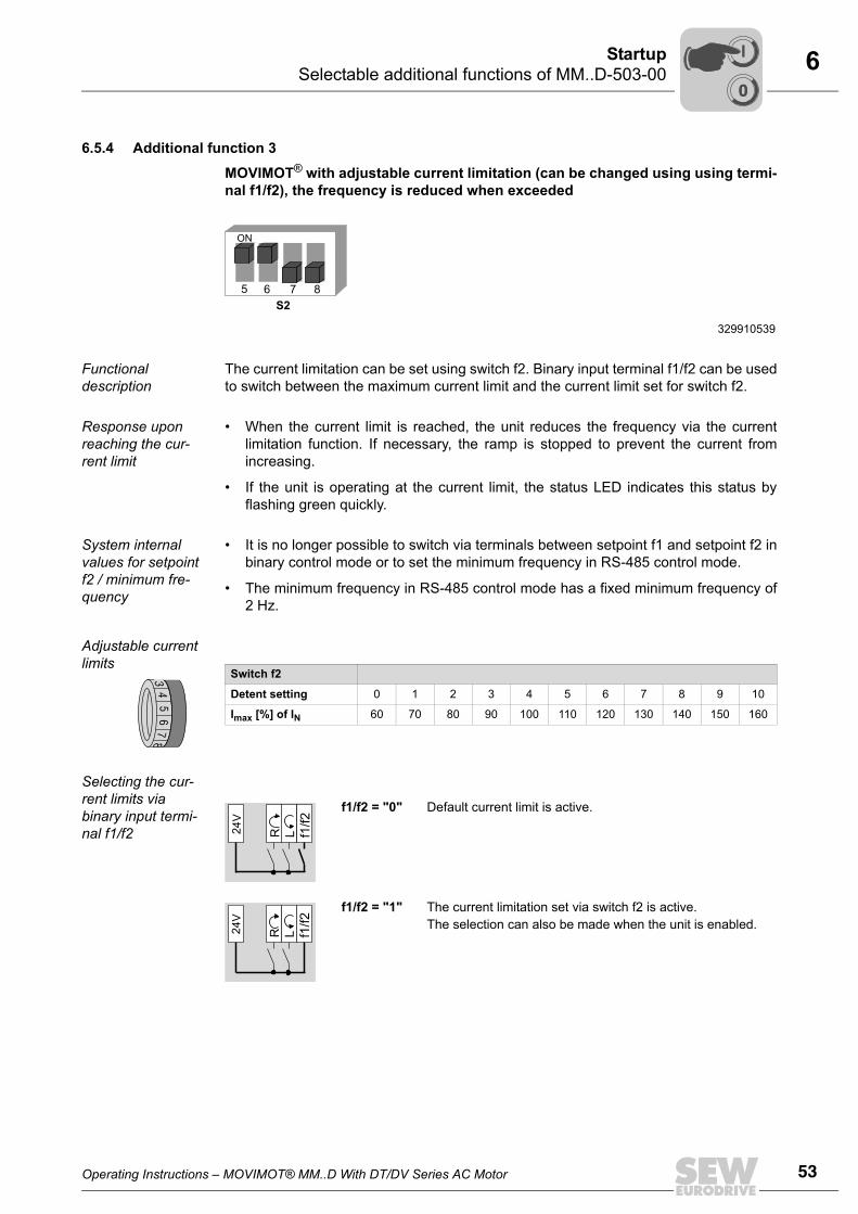
6.5.3 Additional function 2 MOVIMOT® with adjustable current limitation (error if exceeded)
Functional description
• The current limit can be set using switch f2.
• The setpoint f2 (for binary control) and the minimum frequency (for control viaRS-485) are permanently set to the following values:
– Setpoint f2: 5 Hz
– Minimum frequency: 2 Hz
• The monitoring function comes into effect above 15 Hz. If the drive operates at thecurrent limit for longer than 500 ms, the unit generates an error (error 44). This isindicated by the status LED flashing red quickly.
Adjustable current limits
329690891
5 876
S2
ON
Switch t1
Detent setting 0 1 2 3 4 5 6 7 8 9 10
Ramp time t1 [s] 0,1 0,2 0,3 0,5 0,7 1 20 25 30 35 40
= corresponds to standard setting
= changed ramp times
34
56
78
329877131
5 876
S2
ON
Switch f2
Detent setting 0 1 2 3 4 5 6 7 8 9 10
Imax [%] of IN 90 95 100 105 110 115 120 130 140 150 160
34
56
78
00
I
Operating Instructions – MOVIMOT® MM..D With DT/DV Series AC Motor 53
6Selectable additional functions of MM..D-503-00Startup
6.5.4 Additional function 3
MOVIMOT® with adjustable current limitation (can be changed using using termi-nal f1/f2), the frequency is reduced when exceeded
Functional description
The current limitation can be set using switch f2. Binary input terminal f1/f2 can be usedto switch between the maximum current limit and the current limit set for switch f2.
Response upon reaching the cur-rent limit
• When the current limit is reached, the unit reduces the frequency via the currentlimitation function. If necessary, the ramp is stopped to prevent the current fromincreasing.
• If the unit is operating at the current limit, the status LED indicates this status byflashing green quickly.
System internal values for setpoint f2 / minimum fre-quency
• It is no longer possible to switch via terminals between setpoint f1 and setpoint f2 inbinary control mode or to set the minimum frequency in RS-485 control mode.
• The minimum frequency in RS-485 control mode has a fixed minimum frequency of2 Hz.
Adjustable current limits
Selecting the cur-rent limits via binary input termi-nal f1/f2
329910539
5 876
S2
ON
Switch f2
Detent setting 0 1 2 3 4 5 6 7 8 9 10
Imax [%] of IN 60 70 80 90 100 110 120 130 140 150 1603
45
67
8
f1/f2 = "0" Default current limit is active.
f1/f2 = "1" The current limitation set via switch f2 is active. The selection can also be made when the unit is enabled.
R L24V
f1/f2
R L24V
f1/f2
00
I
54 Operating Instructions – MOVIMOT® MM..D With DT/DV Series AC Motor
6 Selectable additional functions of MM..D-503-00Startup
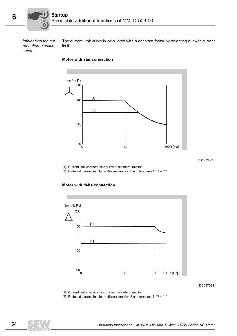
Influencing the cur-rent characteristic curve
The current limit curve is calculated with a constant factor by selecting a lower currentlimit.
Motor with star connection
Motor with delta connection
331979659
[1][2]
Current limit characteristic curve of standard functionReduced current limit for additional function 3 and terminals f1/f2 = "1"
332087051
[1][2]
Current limit characteristic curve of standard functionReduced current limit for additional function 3 and terminals f1/f2 = "1"
200
160
100
500 50 100 f [Hz]
Imax / In [%]
[1]
[2]
200
160
100
500 50 10087
Imax / In [%]
f [Hz]
[1]
[2]
00
I
Operating Instructions – MOVIMOT® MM..D With DT/DV Series AC Motor 55
6Selectable additional functions of MM..D-503-00Startup
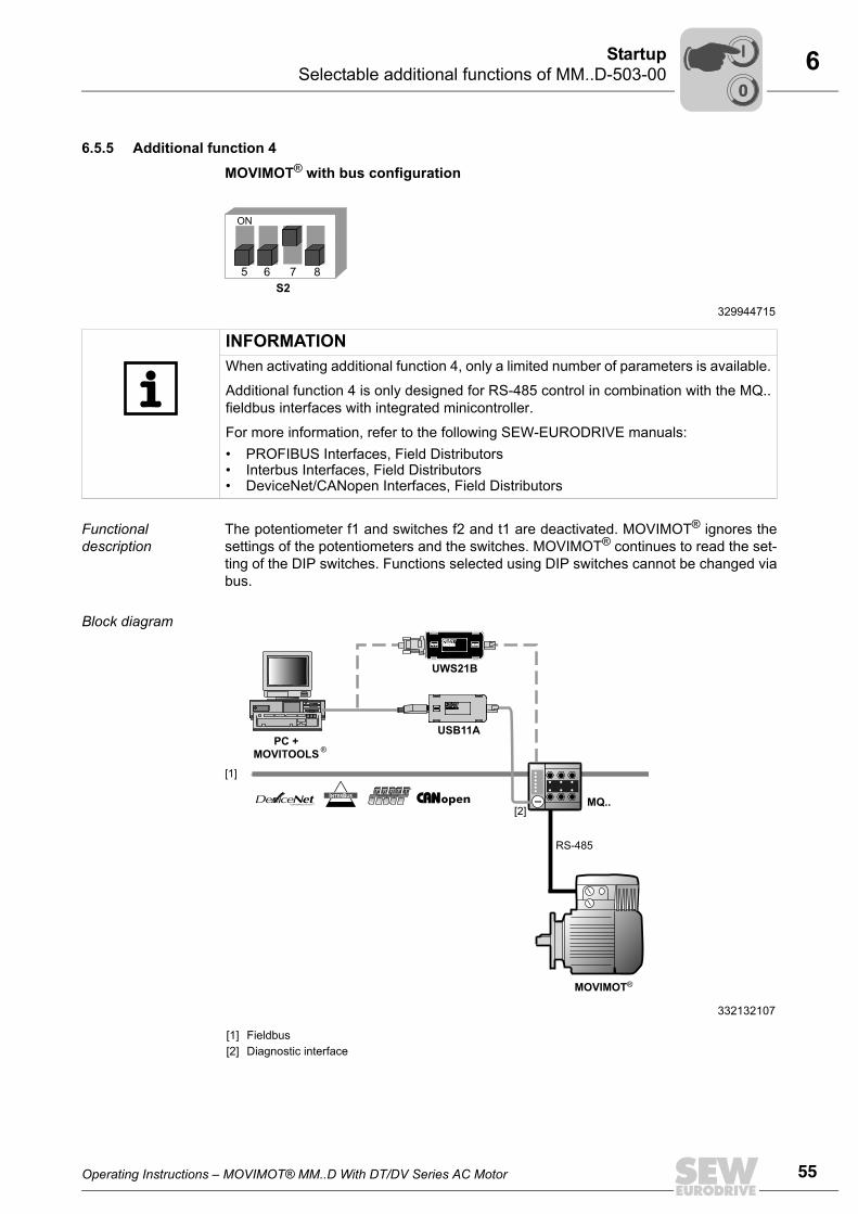
6.5.5 Additional function 4
MOVIMOT® with bus configuration
Functional description
The potentiometer f1 and switches f2 and t1 are deactivated. MOVIMOT® ignores thesettings of the potentiometers and the switches. MOVIMOT® continues to read the set-ting of the DIP switches. Functions selected using DIP switches cannot be changed viabus.
Block diagram
329944715
5 876
S2
ON
INFORMATIONWhen activating additional function 4, only a limited number of parameters is available.
Additional function 4 is only designed for RS-485 control in combination with the MQ..fieldbus interfaces with integrated minicontroller.
For more information, refer to the following SEW-EURODRIVE manuals:• PROFIBUS Interfaces, Field Distributors • Interbus Interfaces, Field Distributors • DeviceNet/CANopen Interfaces, Field Distributors
332132107
[1][2]
FieldbusDiagnostic interface
RS-485
MOVIMOT
MQ..
P R O F I
B U S
®
PROCESS FIELD BUS
[1]
PC +
MOVITOOLS
[2]
USB11A
UWS21B
00
I
56 Operating Instructions – MOVIMOT® MM..D With DT/DV Series AC Motor
6 Selectable additional functions of MM..D-503-00Startup
Changing parameters in MOVITOOLS® MotionStudio
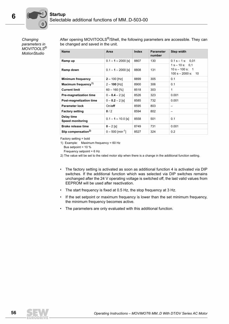
After opening MOVITOOLS®/Shell, the following parameters are accessible. They canbe changed and saved in the unit.
• The factory setting is activated as soon as additional function 4 is activated via DIPswitches. If the additional function which was selected via DIP switches remainsunchanged after the 24 V operating voltage is switched off, the last valid values fromEEPROM will be used after reactivation.
• The start frequency is fixed at 0.5 Hz, the stop frequency at 3 Hz.
• If the set setpoint or maximum frequency is lower than the set minimum frequency,the minimum frequency becomes active.
• The parameters are only evaluated with this additional function.
Name Area Index Parameter number
Step width
Ramp up 0.1 – 1 – 2000 [s] 8807 130 0.1 s – 1 s: 0,011 s – 10 s: 0,110 s – 100 s: 1100 s – 2000 s: 10
Ramp down 0.1 – 1 – 2000 [s] 8808 131
Minimum frequency 2 – 100 [Hz] 8899 305 0.1
Maximum frequency1) 2 – 100 [Hz] 8900 306 0.1
Current limit 60 – 160 [%] 8518 303 1
Pre-magnetization time 0 – 0.4 – 2 [s] 8526 323 0.001
Post-magnetization time 0 – 0.2 – 2 [s] 8585 732 0.001
Parameter lock On/off 8595 803 –
Factory setting 0 / 2 8594 802 –
Delay timeSpeed monitoring 0.1 – 1 – 10.0 [s] 8558 501 0.1
Brake release time 0 – 2 [s] 8749 731 0.001
Slip compensation2) 0 – 500 [min-1] 8527 324 0.2
Factory setting = bold1) Example: Maximum frequency = 60 Hz Bus setpoint = 10 % Frequency setpoint = 6 Hz2) The value will be set to the rated motor slip when there is a change in the additional function setting.
00
I
Operating Instructions – MOVIMOT® MM..D With DT/DV Series AC Motor 57
6Selectable additional functions of MM..D-503-00Startup
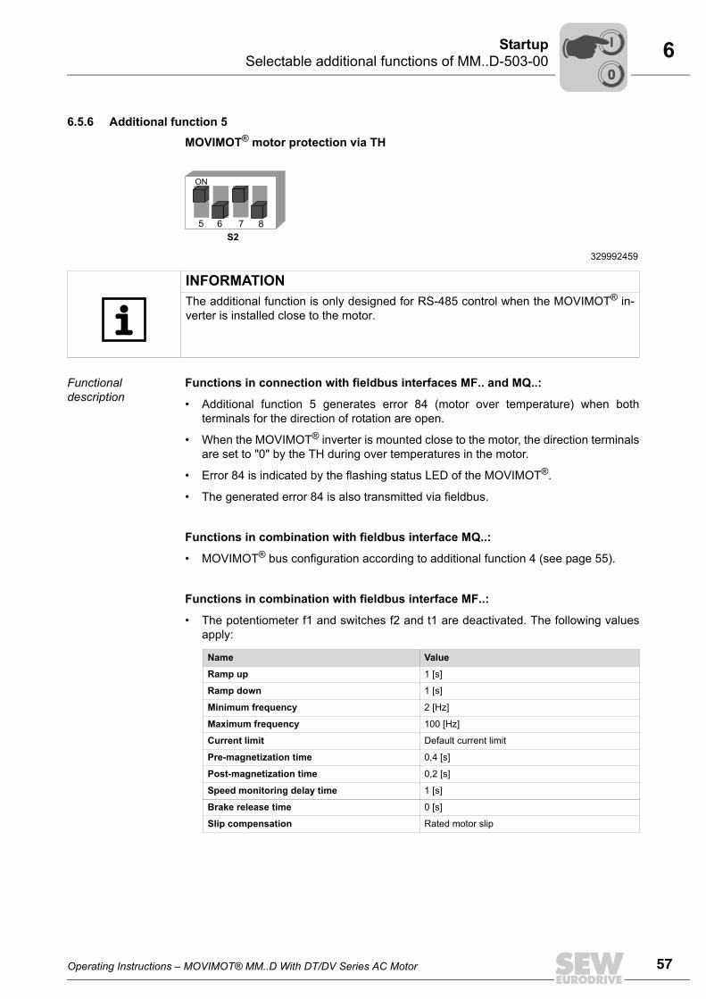
6.5.6 Additional function 5
MOVIMOT® motor protection via TH
Functional description
Functions in connection with fieldbus interfaces MF.. and MQ..:
• Additional function 5 generates error 84 (motor over temperature) when bothterminals for the direction of rotation are open.
• When the MOVIMOT® inverter is mounted close to the motor, the direction terminalsare set to "0" by the TH during over temperatures in the motor.
• Error 84 is indicated by the flashing status LED of the MOVIMOT®.
• The generated error 84 is also transmitted via fieldbus.
Functions in combination with fieldbus interface MQ..:
• MOVIMOT® bus configuration according to additional function 4 (see page 55).
Functions in combination with fieldbus interface MF..:
• The potentiometer f1 and switches f2 and t1 are deactivated. The following valuesapply:
329992459
5 876
S2
ON
INFORMATIONThe additional function is only designed for RS-485 control when the MOVIMOT® in-verter is installed close to the motor.
Name Value
Ramp up 1 [s]
Ramp down 1 [s]
Minimum frequency 2 [Hz]
Maximum frequency 100 [Hz]
Current limit Default current limit
Pre-magnetization time 0,4 [s]
Post-magnetization time 0,2 [s]
Speed monitoring delay time 1 [s]
Brake release time 0 [s]
Slip compensation Rated motor slip
00
I
58 Operating Instructions – MOVIMOT® MM..D With DT/DV Series AC Motor
6 Selectable additional functions of MM..D-503-00Startup
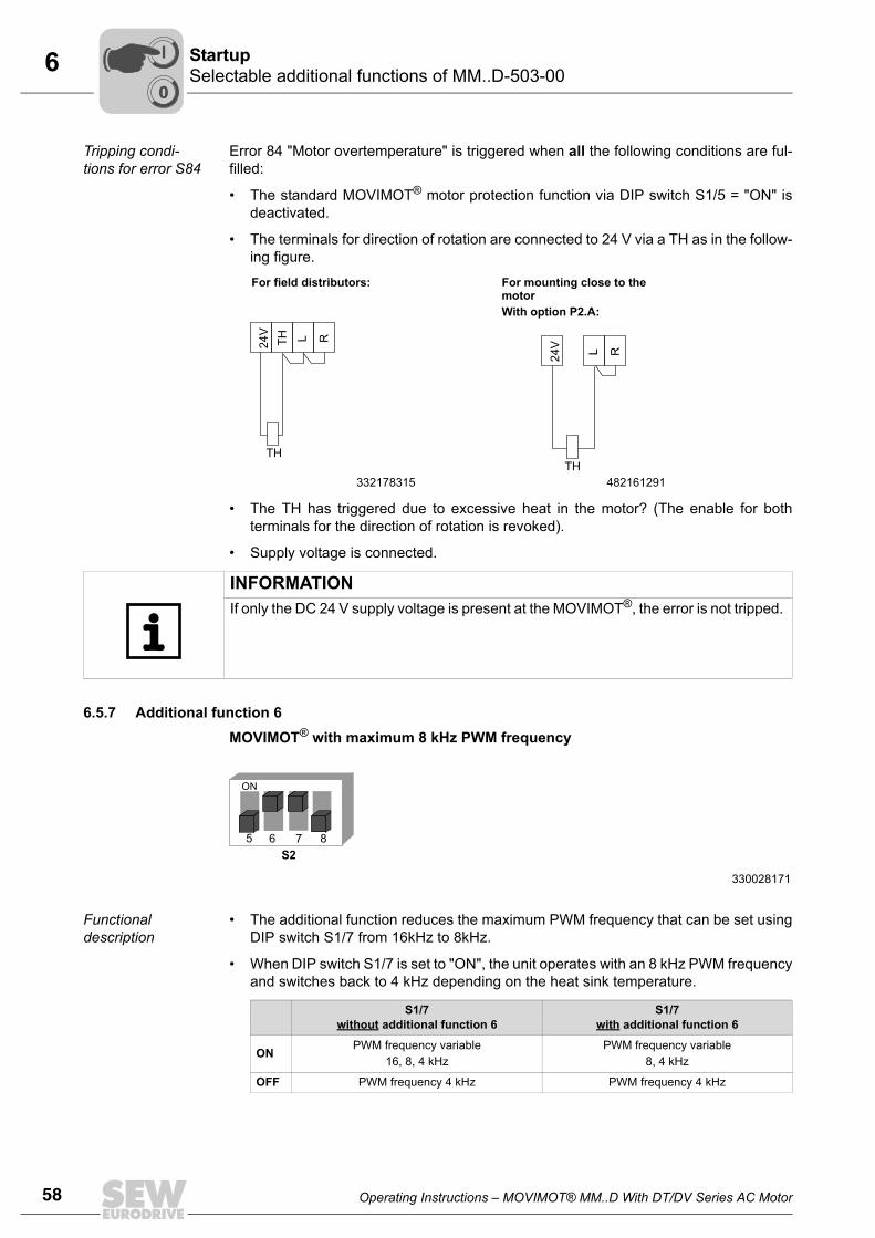
Tripping condi-tions for error S84
Error 84 "Motor overtemperature" is triggered when all the following conditions are ful-filled:
• The standard MOVIMOT® motor protection function via DIP switch S1/5 = "ON" isdeactivated.
• The terminals for direction of rotation are connected to 24 V via a TH as in the follow-ing figure.
• The TH has triggered due to excessive heat in the motor? (The enable for bothterminals for the direction of rotation is revoked).
• Supply voltage is connected.
6.5.7 Additional function 6MOVIMOT® with maximum 8 kHz PWM frequency
Functional description
• The additional function reduces the maximum PWM frequency that can be set usingDIP switch S1/7 from 16kHz to 8kHz.
• When DIP switch S1/7 is set to "ON", the unit operates with an 8 kHz PWM frequencyand switches back to 4 kHz depending on the heat sink temperature.
For field distributors: For mounting close to the motorWith option P2.A:
332178315 482161291
24V
TH L R
TH
24V
L R
TH
INFORMATIONIf only the DC 24 V supply voltage is present at the MOVIMOT®, the error is not tripped.
330028171
5 876
S2
ON
S1/7 without additional function 6
S1/7 with additional function 6
ON PWM frequency variable16, 8, 4 kHz
PWM frequency variable8, 4 kHz
OFF PWM frequency 4 kHz PWM frequency 4 kHz
00
I
Operating Instructions – MOVIMOT® MM..D With DT/DV Series AC Motor 59
6Selectable additional functions of MM..D-503-00Startup
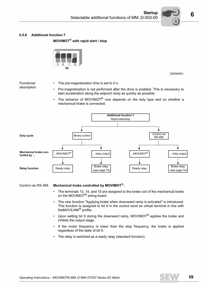
6.5.8 Additional function 7
MOVIMOT® with rapid start / stop
Functional description
• The pre-magnetization time is set to 0 s.
• Pre-magnetization is not performed after the drive is enabled. This is necessary tostart acceleration along the setpoint ramp as quickly as possible.
• The behavior of MOVIMOT® now depends on the duty type and on whether amechanical brake is connected.
Control via RS-485 Mechanical brake controlled by MOVIMOT®:
• The terminals 13, 14, and 15 are assigned to the brake coil of the mechanical brakeon the MOVIMOT® wiring board.
• The new function "Applying brake when downward ramp is activated" is introduced.This function is assigned to bit 9 in the control word as virtual terminal in line withtheMOVILINK® profile.
• Upon setting bit 9 during the downward ramp, MOVIMOT® applies the brake andinhibits the output stage.
• If the motor frequency is lower than the stop frequency, the brake is appliedregardless of the state of bit 9.
• The relay is switched as a ready relay (standard function).
330064651
5 876
S2
ON
Additional function 7Rapid start/stop
Duty cycle Binary control Control via RS-485
Mechanical brake con-trolled by ... ...MOVIMOT® ... relay output ...MOVIMOT® ... relay output
Relay function Ready relayBrake relay
(see page 74)Ready relay
Brake relay (see page 74)
00
I
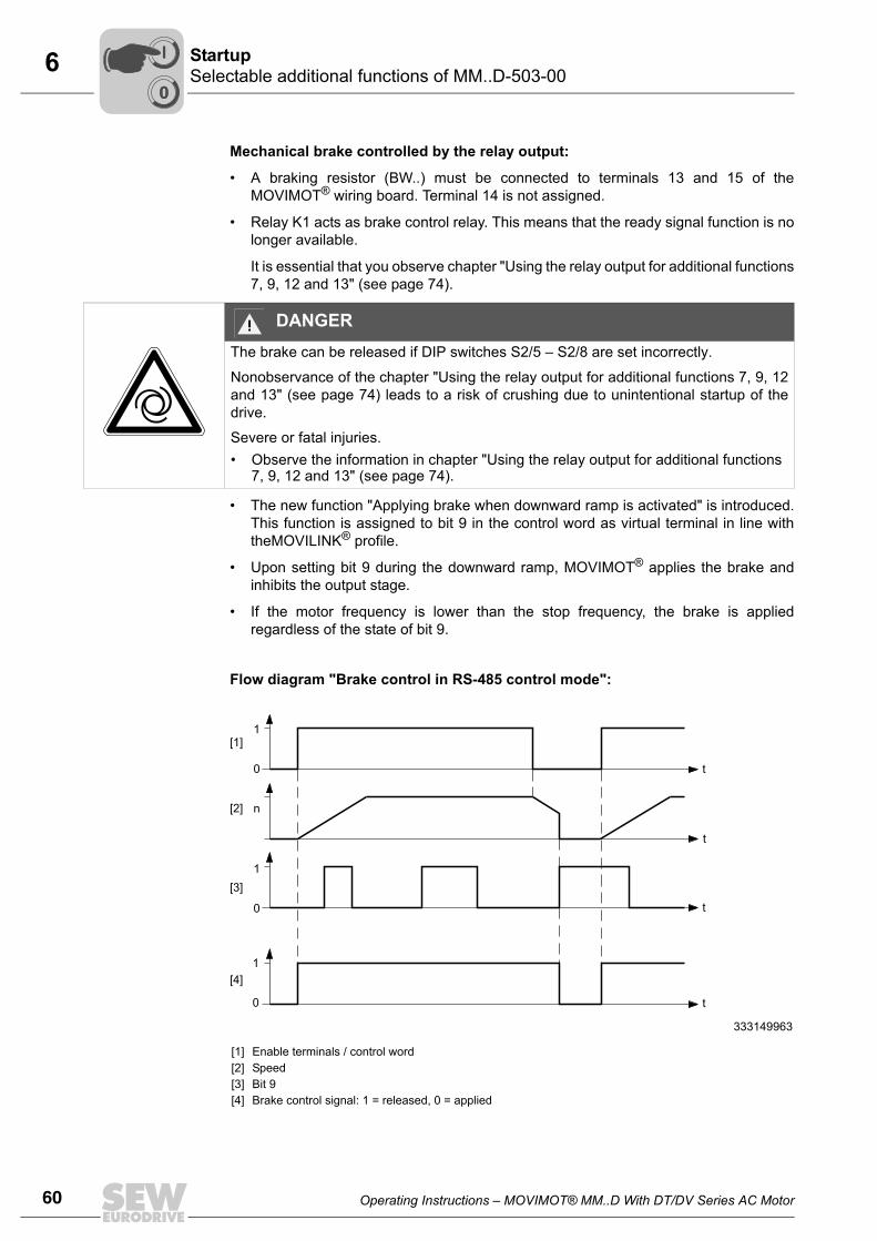
60 Operating Instructions – MOVIMOT® MM..D With DT/DV Series AC Motor
6 Selectable additional functions of MM..D-503-00Startup
Mechanical brake controlled by the relay output:
• A braking resistor (BW..) must be connected to terminals 13 and 15 of theMOVIMOT® wiring board. Terminal 14 is not assigned.
• Relay K1 acts as brake control relay. This means that the ready signal function is nolonger available.
It is essential that you observe chapter "Using the relay output for additional functions7, 9, 12 and 13" (see page 74).
• The new function "Applying brake when downward ramp is activated" is introduced.This function is assigned to bit 9 in the control word as virtual terminal in line withtheMOVILINK® profile.
• Upon setting bit 9 during the downward ramp, MOVIMOT® applies the brake andinhibits the output stage.
• If the motor frequency is lower than the stop frequency, the brake is appliedregardless of the state of bit 9.
Flow diagram "Brake control in RS-485 control mode":
DANGERThe brake can be released if DIP switches S2/5 – S2/8 are set incorrectly.
Nonobservance of the chapter "Using the relay output for additional functions 7, 9, 12and 13" (see page 74) leads to a risk of crushing due to unintentional startup of thedrive.
Severe or fatal injuries.• Observe the information in chapter "Using the relay output for additional functions
7, 9, 12 and 13" (see page 74).
333149963
[1][2][3][4]
Enable terminals / control wordSpeedBit 9Brake control signal: 1 = released, 0 = applied
[1]
[2]
[3]
[4]
1
0
n
1
0
1
0
t
t
t
t
00
I
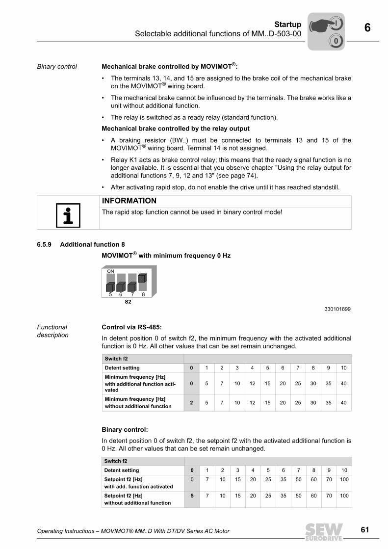
Operating Instructions – MOVIMOT® MM..D With DT/DV Series AC Motor 61
6Selectable additional functions of MM..D-503-00Startup
Binary control Mechanical brake controlled by MOVIMOT®:
• The terminals 13, 14, and 15 are assigned to the brake coil of the mechanical brakeon the MOVIMOT® wiring board.
• The mechanical brake cannot be influenced by the terminals. The brake works like aunit without additional function.
• The relay is switched as a ready relay (standard function).
Mechanical brake controlled by the relay output
• A braking resistor (BW..) must be connected to terminals 13 and 15 of theMOVIMOT® wiring board. Terminal 14 is not assigned.
• Relay K1 acts as brake control relay; this means that the ready signal function is nolonger available. It is essential that you observe chapter "Using the relay output foradditional functions 7, 9, 12 and 13" (see page 74).
• After activating rapid stop, do not enable the drive until it has reached standstill.
6.5.9 Additional function 8 MOVIMOT® with minimum frequency 0 Hz
Functional description
Control via RS-485:In detent position 0 of switch f2, the minimum frequency with the activated additionalfunction is 0 Hz. All other values that can be set remain unchanged.
Binary control:In detent position 0 of switch f2, the setpoint f2 with the activated additional function is0 Hz. All other values that can be set remain unchanged.
INFORMATIONThe rapid stop function cannot be used in binary control mode!
330101899
5 876
S2
ON
Switch f2
Detent setting 0 1 2 3 4 5 6 7 8 9 10
Minimum frequency [Hz] with additional function acti-vated
0 5 7 10 12 15 20 25 30 35 40
Minimum frequency [Hz] without additional function 2 5 7 10 12 15 20 25 30 35 40
Switch f2
Detent setting 0 1 2 3 4 5 6 7 8 9 10
Setpoint f2 [Hz]with add. function activated
0 7 10 15 20 25 35 50 60 70 100
Setpoint f2 [Hz]without additional function
5 7 10 15 20 25 35 50 60 70 100
00
I
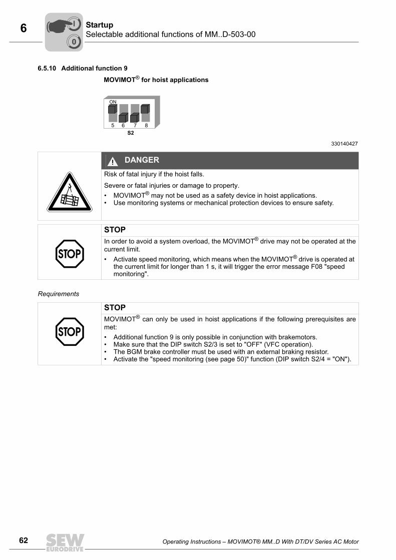
62 Operating Instructions – MOVIMOT® MM..D With DT/DV Series AC Motor
6 Selectable additional functions of MM..D-503-00Startup
6.5.10 Additional function 9
MOVIMOT® for hoist applications
Requirements
330140427
5 876
S2
ON
DANGERRisk of fatal injury if the hoist falls.
Severe or fatal injuries or damage to property.• MOVIMOT® may not be used as a safety device in hoist applications.• Use monitoring systems or mechanical protection devices to ensure safety.
STOPIn order to avoid a system overload, the MOVIMOT® drive may not be operated at thecurrent limit.• Activate speed monitoring, which means when the MOVIMOT® drive is operated at
the current limit for longer than 1 s, it will trigger the error message F08 "speed monitoring".
STOPMOVIMOT® can only be used in hoist applications if the following prerequisites aremet:• Additional function 9 is only possible in conjunction with brakemotors.• Make sure that the DIP switch S2/3 is set to "OFF" (VFC operation).• The BGM brake controller must be used with an external braking resistor.• Activate the "speed monitoring (see page 50)" function (DIP switch S2/4 = "ON").
00
I
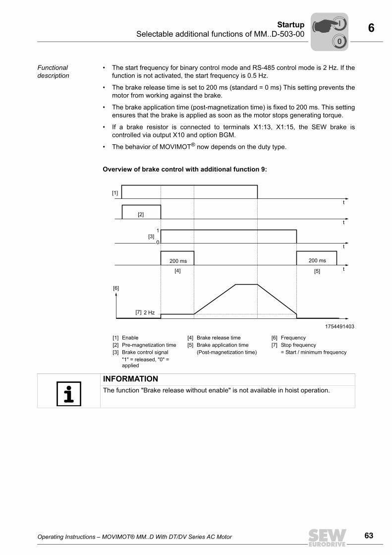
Operating Instructions – MOVIMOT® MM..D With DT/DV Series AC Motor 63
6Selectable additional functions of MM..D-503-00Startup
Functional description
• The start frequency for binary control mode and RS-485 control mode is 2 Hz. If thefunction is not activated, the start frequency is 0.5 Hz.
• The brake release time is set to 200 ms (standard = 0 ms) This setting prevents themotor from working against the brake.
• The brake application time (post-magnetization time) is fixed to 200 ms. This settingensures that the brake is applied as soon as the motor stops generating torque.
• If a brake resistor is connected to terminals X1:13, X1:15, the SEW brake iscontrolled via output X10 and option BGM.
• The behavior of MOVIMOT® now depends on the duty type.
Overview of brake control with additional function 9:
1754491403
[1][2][3]
EnablePre-magnetization timeBrake control signal"1" = released, "0" = applied
[4][5]
Brake release timeBrake application time (Post-magnetization time)
[6][7]
FrequencyStop frequency= Start / minimum frequency
[1]
t
t
t
t200 ms200 ms
2 Hz
[2]
[3]
[5][4]
[6]
[7]
1
0
INFORMATIONThe function "Brake release without enable" is not available in hoist operation.
00
I
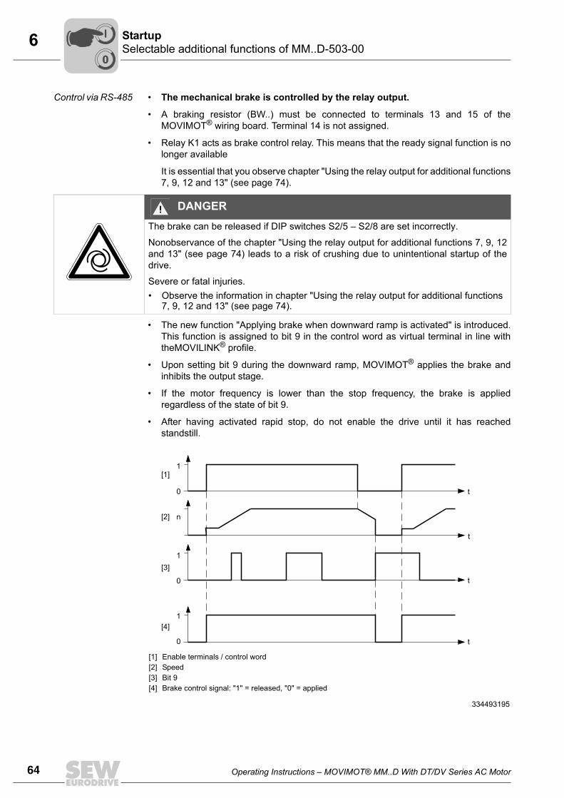
64 Operating Instructions – MOVIMOT® MM..D With DT/DV Series AC Motor
6 Selectable additional functions of MM..D-503-00Startup
Control via RS-485 • The mechanical brake is controlled by the relay output.
• A braking resistor (BW..) must be connected to terminals 13 and 15 of theMOVIMOT® wiring board. Terminal 14 is not assigned.
• Relay K1 acts as brake control relay. This means that the ready signal function is nolonger available
It is essential that you observe chapter "Using the relay output for additional functions7, 9, 12 and 13" (see page 74).
• The new function "Applying brake when downward ramp is activated" is introduced.This function is assigned to bit 9 in the control word as virtual terminal in line withtheMOVILINK® profile.
• Upon setting bit 9 during the downward ramp, MOVIMOT® applies the brake andinhibits the output stage.
• If the motor frequency is lower than the stop frequency, the brake is appliedregardless of the state of bit 9.
• After having activated rapid stop, do not enable the drive until it has reachedstandstill.
DANGERThe brake can be released if DIP switches S2/5 – S2/8 are set incorrectly.
Nonobservance of the chapter "Using the relay output for additional functions 7, 9, 12and 13" (see page 74) leads to a risk of crushing due to unintentional startup of thedrive.
Severe or fatal injuries.• Observe the information in chapter "Using the relay output for additional functions
7, 9, 12 and 13" (see page 74).
[1] [2][3] [4]
Enable terminals / control wordSpeedBit 9Brake control signal: "1" = released, "0" = applied
334493195
t
t
t
t
[1]
[2]
[3]
[4]
1
0
n
1
0
1
0
00
I
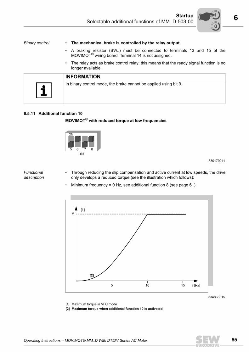
Operating Instructions – MOVIMOT® MM..D With DT/DV Series AC Motor 65
6Selectable additional functions of MM..D-503-00Startup
Binary control • The mechanical brake is controlled by the relay output.
• A braking resistor (BW..) must be connected to terminals 13 and 15 of theMOVIMOT® wiring board. Terminal 14 is not assigned.
• The relay acts as brake control relay; this means that the ready signal function is nolonger available.
6.5.11 Additional function 10MOVIMOT® with reduced torque at low frequencies
Functional description
• Through reducing the slip compensation and active current at low speeds, the driveonly develops a reduced torque (see the illustration which follows):
• Minimum frequency = 0 Hz, see additional function 8 (see page 61).
INFORMATIONIn binary control mode, the brake cannot be applied using bit 9.
330179211
5 876
S2
ON
334866315
[1][2]
Maximum torque in VFC modeMaximum torque when additional function 10 is activated
M
5
[1]
[2]
10 15 f [Hz]
00
I
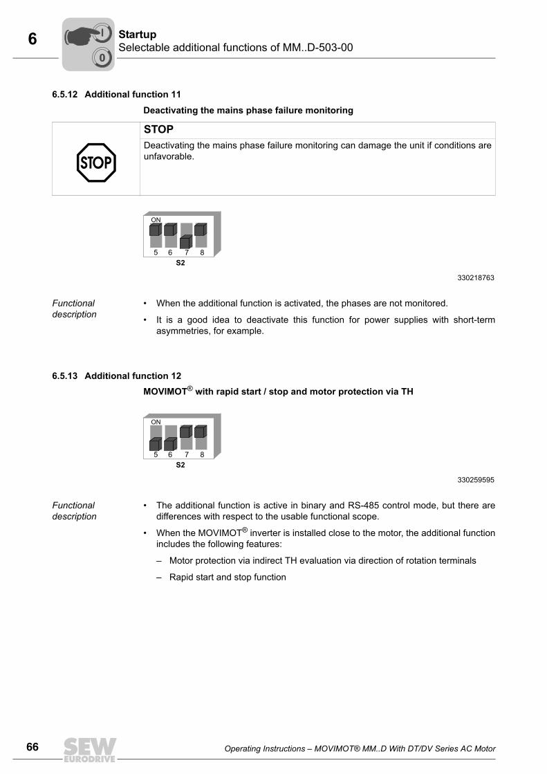
66 Operating Instructions – MOVIMOT® MM..D With DT/DV Series AC Motor
6 Selectable additional functions of MM..D-503-00Startup
6.5.12 Additional function 11
Deactivating the mains phase failure monitoring
Functional description
• When the additional function is activated, the phases are not monitored.
• It is a good idea to deactivate this function for power supplies with short-termasymmetries, for example.
6.5.13 Additional function 12MOVIMOT® with rapid start / stop and motor protection via TH
Functional description
• The additional function is active in binary and RS-485 control mode, but there aredifferences with respect to the usable functional scope.
• When the MOVIMOT® inverter is installed close to the motor, the additional functionincludes the following features:
– Motor protection via indirect TH evaluation via direction of rotation terminals
– Rapid start and stop function
STOPDeactivating the mains phase failure monitoring can damage the unit if conditions areunfavorable.
330218763
5 876
S2
ON
330259595
5 876
S2
ON
00
I
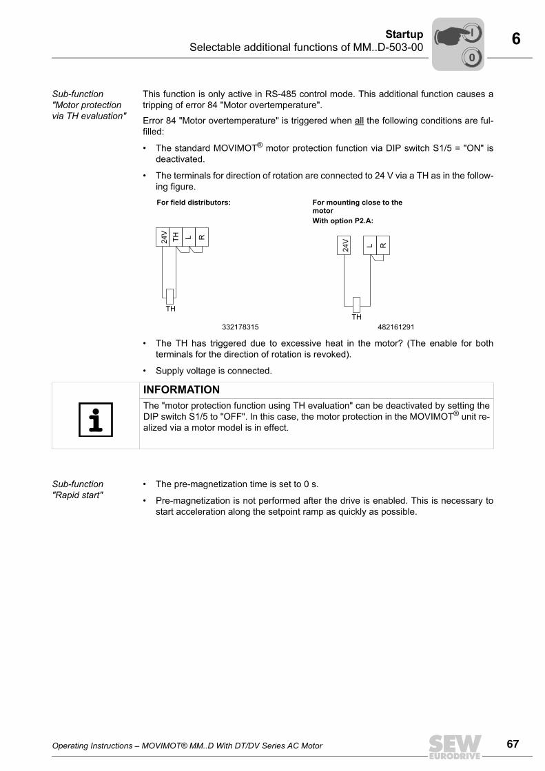
Operating Instructions – MOVIMOT® MM..D With DT/DV Series AC Motor 67
6Selectable additional functions of MM..D-503-00Startup
Sub-function "Motor protection via TH evaluation"
This function is only active in RS-485 control mode. This additional function causes atripping of error 84 "Motor overtemperature".
Error 84 "Motor overtemperature" is triggered when all the following conditions are ful-filled:
• The standard MOVIMOT® motor protection function via DIP switch S1/5 = "ON" isdeactivated.
• The terminals for direction of rotation are connected to 24 V via a TH as in the follow-ing figure.
• The TH has triggered due to excessive heat in the motor? (The enable for bothterminals for the direction of rotation is revoked).
• Supply voltage is connected.
Sub-function "Rapid start"
• The pre-magnetization time is set to 0 s.
• Pre-magnetization is not performed after the drive is enabled. This is necessary tostart acceleration along the setpoint ramp as quickly as possible.
For field distributors: For mounting close to the motorWith option P2.A:
332178315 482161291
24V
TH L R
TH
24V
L R
TH
INFORMATIONThe "motor protection function using TH evaluation" can be deactivated by setting theDIP switch S1/5 to "OFF". In this case, the motor protection in the MOVIMOT® unit re-alized via a motor model is in effect.
00
I
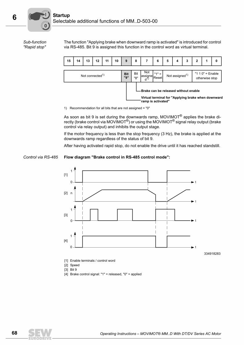
68 Operating Instructions – MOVIMOT® MM..D With DT/DV Series AC Motor
6 Selectable additional functions of MM..D-503-00Startup
Sub-function "Rapid stop"
The function "Applying brake when downward ramp is activated" is introduced for controlvia RS-485. Bit 9 is assigned this function in the control word as virtual terminal.
As soon as bit 9 is set during the downwards ramp, MOVIMOT® applies the brake di-rectly (brake control via MOVIMOT®) or using the MOVIMOT® signal relay output (brakecontrol via relay output) and inhibits the output stage.
If the motor frequency is less than the stop frequency (3 Hz), the brake is applied at thedownwards ramp regardless of the status of bit 9.
After having activated rapid stop, do not enable the drive until it has reached standstill.
Control via RS-485 Flow diagram "Brake control in RS-485 control mode":
15 14 13 12 11 10 9 8 7 6 5 4 3 2 1 0
Not connected1)
1) Recommendation for all bits that are not assigned = "0"
Bit "9"
Bit"8"
Not assigne
d1)"1" = Reset Not assigned1) "1 1 0" = Enable
otherwise stop
Brake can be released without enable
Virtual terminal for "Applying brake when downward ramp is activated"
334918283
[1][2][3][4]
Enable terminals / control wordSpeedBit 9Brake control signal: "1" = released, "0" = applied
[1]
[2]
[3]
[4]
1
0
n
1
0
1
0
t
t
t
t
00
I
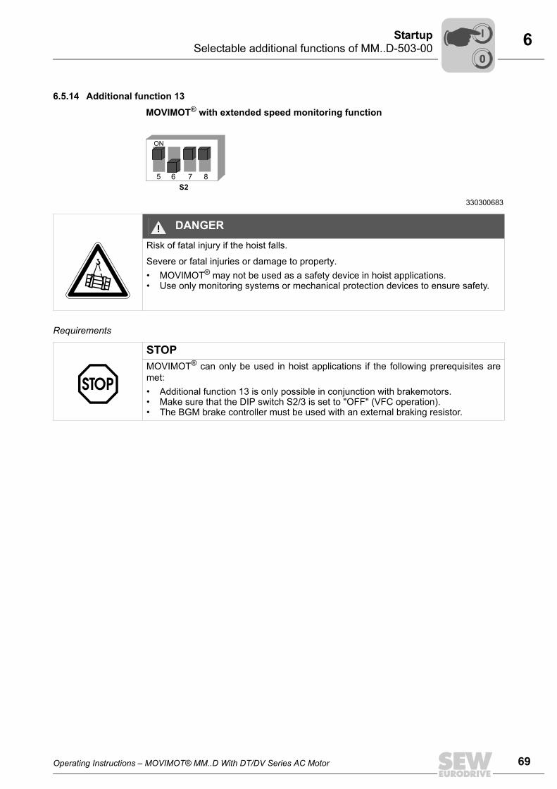
Operating Instructions – MOVIMOT® MM..D With DT/DV Series AC Motor 69
6Selectable additional functions of MM..D-503-00Startup
6.5.14 Additional function 13
MOVIMOT® with extended speed monitoring function
Requirements
330300683
5 876
S2
ON
DANGERRisk of fatal injury if the hoist falls.
Severe or fatal injuries or damage to property.• MOVIMOT® may not be used as a safety device in hoist applications.• Use only monitoring systems or mechanical protection devices to ensure safety.
STOPMOVIMOT® can only be used in hoist applications if the following prerequisites aremet:• Additional function 13 is only possible in conjunction with brakemotors.• Make sure that the DIP switch S2/3 is set to "OFF" (VFC operation).• The BGM brake controller must be used with an external braking resistor.
00
I
70 Operating Instructions – MOVIMOT® MM..D With DT/DV Series AC Motor
6 Selectable additional functions of MM..D-503-00Startup
Functional description
Additional function 13 includes the following functions:
• Additional function 9, MOVIMOT® for hoist applications
• Speed monitoring with adjustable monitoring time
Once additional function 13 is activated, speed monitoring is always on, regardless ofthe setting of DIP switch S2/4.
After activating additional function 13, the DIP switch S2/4 had the following functionsdepending on the set RS-485 address:
Binary control The RS-485 address set at DIP switches S1/1 to S1/4 is 0.
• S2/4 = "OFF"
– The speed monitoring time 2 is set at switch t1.
– The speed monitoring times 1 and 3 are fixed to 1 s.
– The ramp time is fixed to 1 s.
– Setpoint f2 is set as switch f2.
• S2/4 = "ON"
– The speed monitoring time 2 is set at switch f2.
– The speed monitoring times 1 and 3 are fixed to 1 s.
– The setpoint is fixed at 5 Hz.
– The ramp time is set at switch t1.
Control via RS-485 The RS-485 address set at DIP switches S1/1 to S1/4 is not 0.
• S2/4 = "OFF"
– The speed monitoring time 2 is set at switch t1.
– The speed monitoring times 1 and 3 are set at switch f2.
– The ramp time is fixed to 1 s.
– The minimum frequency is fixed at 2 Hz.
• S2/4 = "ON"
– The speed monitoring time 2 is set at switch f2.
– The speed monitoring times 1 and 3 are fixed to 1 s.
– The ramp time is set at switch t1.
– The minimum frequency is fixed at 2 Hz.
00
I
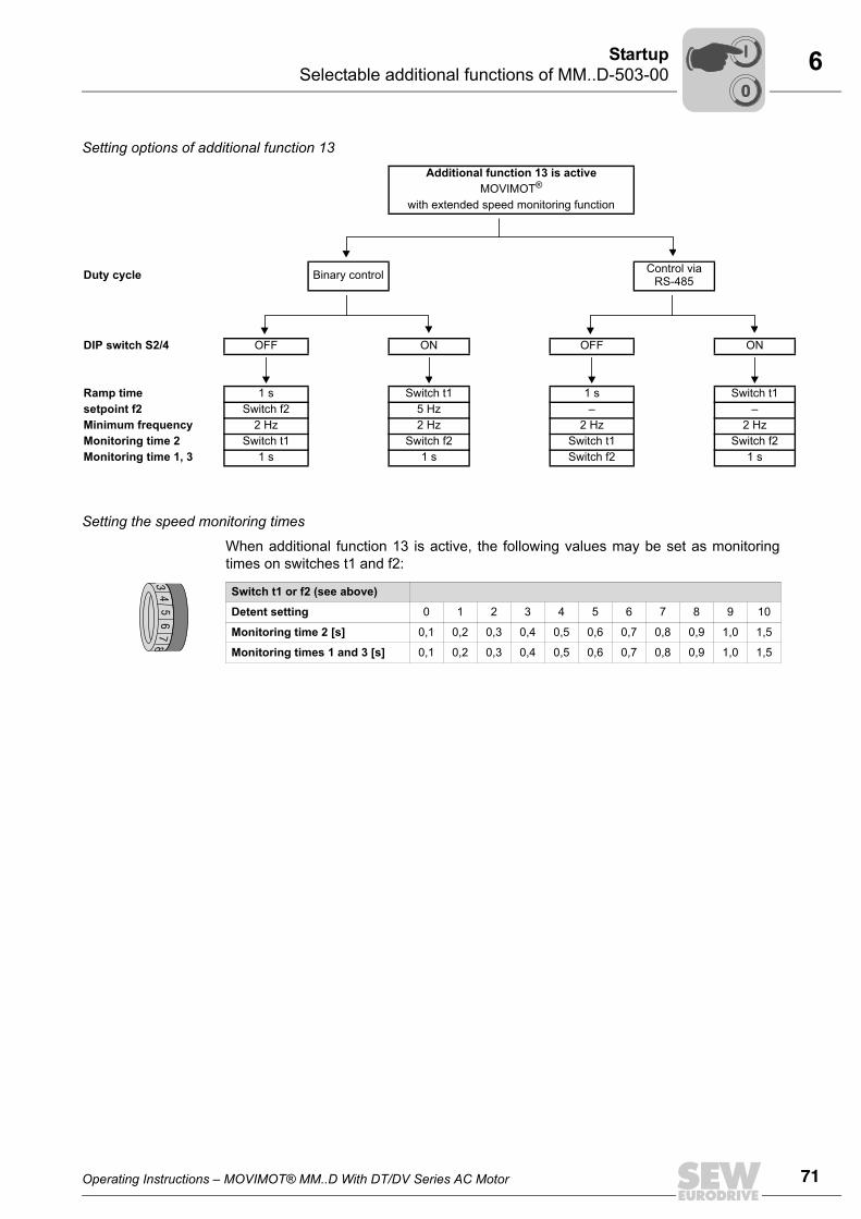
Operating Instructions – MOVIMOT® MM..D With DT/DV Series AC Motor 71
6Selectable additional functions of MM..D-503-00Startup
Setting options of additional function 13
Setting the speed monitoring times
When additional function 13 is active, the following values may be set as monitoringtimes on switches t1 and f2:
Additional function 13 is activeMOVIMOT®
with extended speed monitoring function
Duty cycle Binary control Control via RS-485
DIP switch S2/4 OFF ON OFF ON
Ramp time 1 s Switch t1 1 s Switch t1setpoint f2 Switch f2 5 Hz – –Minimum frequency 2 Hz 2 Hz 2 Hz 2 HzMonitoring time 2 Switch t1 Switch f2 Switch t1 Switch f2Monitoring time 1, 3 1 s 1 s Switch f2 1 s
Switch t1 or f2 (see above)
Detent setting 0 1 2 3 4 5 6 7 8 9 10
Monitoring time 2 [s] 0,1 0,2 0,3 0,4 0,5 0,6 0,7 0,8 0,9 1,0 1,5
Monitoring times 1 and 3 [s] 0,1 0,2 0,3 0,4 0,5 0,6 0,7 0,8 0,9 1,0 1,5
34
56
78
00
I
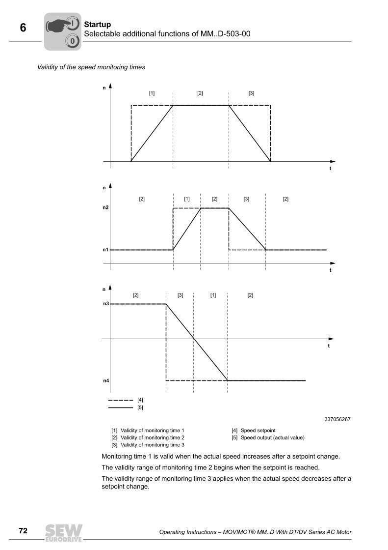
72 Operating Instructions – MOVIMOT® MM..D With DT/DV Series AC Motor
6 Selectable additional functions of MM..D-503-00Startup
Validity of the speed monitoring times
Monitoring time 1 is valid when the actual speed increases after a setpoint change.
The validity range of monitoring time 2 begins when the setpoint is reached.
The validity range of monitoring time 3 applies when the actual speed decreases after asetpoint change.
337056267
[1] [2] [3]
Validity of monitoring time 1Validity of monitoring time 2Validity of monitoring time 3
[4] [5]
Speed setpointSpeed output (actual value)
t
n
t
n
t
n
n1
n2
n3
n4
[1] [2]
[2]
[2]
[4][5]
[3] [1] [2]
[1] [2] [3] [2]
[3]
00
I
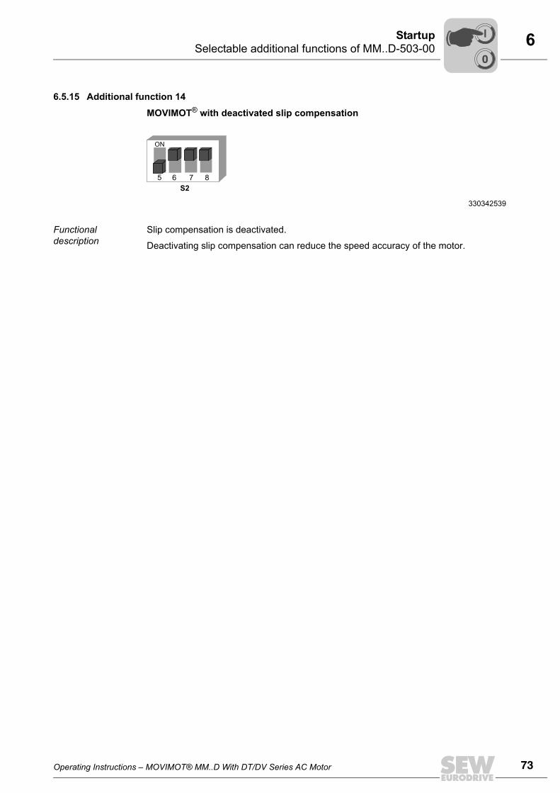
Operating Instructions – MOVIMOT® MM..D With DT/DV Series AC Motor 73
6Selectable additional functions of MM..D-503-00Startup
6.5.15 Additional function 14
MOVIMOT® with deactivated slip compensation
Functional description
Slip compensation is deactivated.
Deactivating slip compensation can reduce the speed accuracy of the motor.
330342539
5 876
S2
ON
00
I
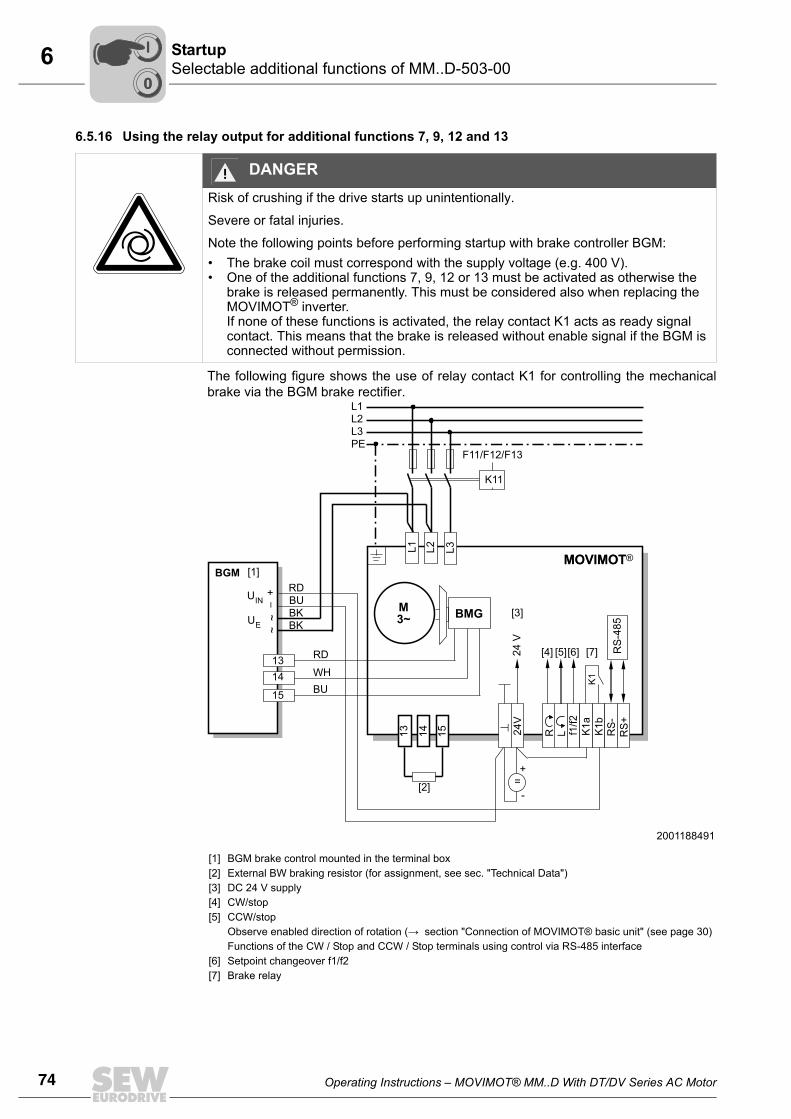
74 Operating Instructions – MOVIMOT® MM..D With DT/DV Series AC Motor
6 Selectable additional functions of MM..D-503-00Startup
6.5.16 Using the relay output for additional functions 7, 9, 12 and 13
The following figure shows the use of relay contact K1 for controlling the mechanicalbrake via the BGM brake rectifier.
DANGERRisk of crushing if the drive starts up unintentionally.
Severe or fatal injuries.
Note the following points before performing startup with brake controller BGM:• The brake coil must correspond with the supply voltage (e.g. 400 V).• One of the additional functions 7, 9, 12 or 13 must be activated as otherwise the
brake is released permanently. This must be considered also when replacing the MOVIMOT® inverter.If none of these functions is activated, the relay contact K1 acts as ready signal contact. This means that the brake is released without enable signal if the BGM is connected without permission.
2001188491
[1][2][3][4][5]
[6][7]
BGM brake control mounted in the terminal box External BW braking resistor (for assignment, see sec. "Technical Data")DC 24 V supplyCW/stop CCW/stop Observe enabled direction of rotation (→ section "Connection of MOVIMOT® basic unit" (see page 30) Functions of the CW / Stop and CCW / Stop terminals using control via RS-485 interfaceSetpoint changeover f1/f2Brake relay
M3~
L1L2L3PE
K11
F11/F12/F13
K1
RS
-485
13
RD
RD
BKBK
WHBU
BU
14 15L3
24V
R L f1/f2
K1a
K1b
RS-
RS+
=+
-
MOVIMOT
+~
~
[1]
[2]
[3]
[4] [5][6] [7]
BMG
BGMMOVIMOT
24
V
1314
15
L1 L2
_
UIN
UE
00
I
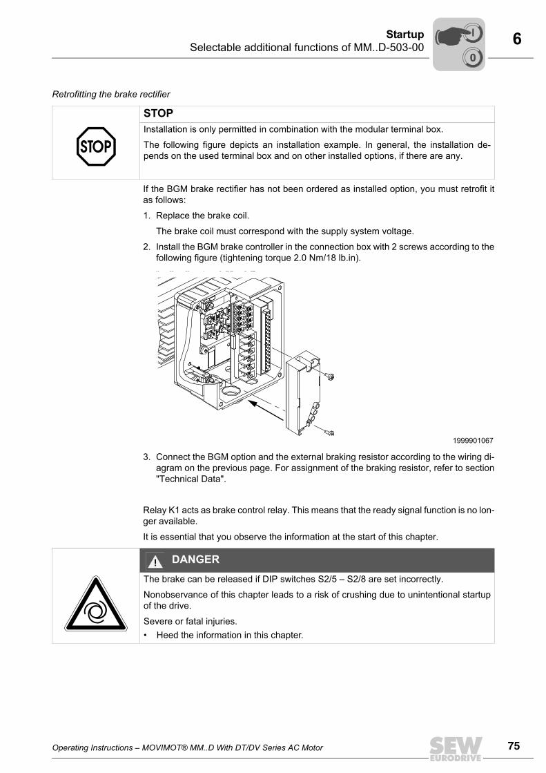
Operating Instructions – MOVIMOT® MM..D With DT/DV Series AC Motor 75
6Selectable additional functions of MM..D-503-00Startup
Retrofitting the brake rectifier
If the BGM brake rectifier has not been ordered as installed option, you must retrofit itas follows:
1. Replace the brake coil.
The brake coil must correspond with the supply system voltage.
2. Install the BGM brake controller in the connection box with 2 screws according to thefollowing figure (tightening torque 2.0 Nm/18 lb.in).
3. Connect the BGM option and the external braking resistor according to the wiring di-agram on the previous page. For assignment of the braking resistor, refer to section"Technical Data".
Relay K1 acts as brake control relay. This means that the ready signal function is no lon-ger available.
It is essential that you observe the information at the start of this chapter.
STOPInstallation is only permitted in combination with the modular terminal box.
The following figure depicts an installation example. In general, the installation de-pends on the used terminal box and on other installed options, if there are any.
1999901067
DANGERThe brake can be released if DIP switches S2/5 – S2/8 are set incorrectly.
Nonobservance of this chapter leads to a risk of crushing due to unintentional startupof the drive.
Severe or fatal injuries.• Heed the information in this chapter.
00
I

76 Operating Instructions – MOVIMOT® MM..D With DT/DV Series AC Motor
6 Startup with binary controlStartup
6.6 Startup with binary control
1. Check the connection of the MOVIMOT® inverter.
See section "Electrical Installation".
2. Make sure that the DIP switches S1/1 – S1/4 are set to "OFF" (address = 0).
This means MOVIMOT® is controlled binary via terminals.
3. Set the first speed at the setpoint potentiometer f1 (active when terminals f1/f2 = "0")(factory setting: about 1500 rpm (50 Hz).
4. Make sure the screw plug of the setpoint potentiometer f1 has a seal and screw it in.
DANGERWhen working on the unit, dangerous voltage levels may still be present up to one min-ute after the mains is disconnected.
Severe or fatal injuries from electric shock.• Disconnect the MOVIMOT® drive from the power supply using an appropriate
external disconnecting device and secure it against unintentional reconnection to the voltage supply.
• Then wait at least for 1 minute.
337484811
329413003
[1] Potentiometer setting
1
ON
6 7 854321
ON
432
1 2 3 4 5 6 7 8 9 100
100f [Hz
[1]
]
2
75
25
50
65f1
STOPThe enclosure specified in section Technical Data only applies if the screw plugs of thesetpoint potentiometer and the X50 diagnostic interface are installed correctly.
A missing or incorrectly installed screw plug can cause damage to the MOVIMOT® in-verter.
00
I
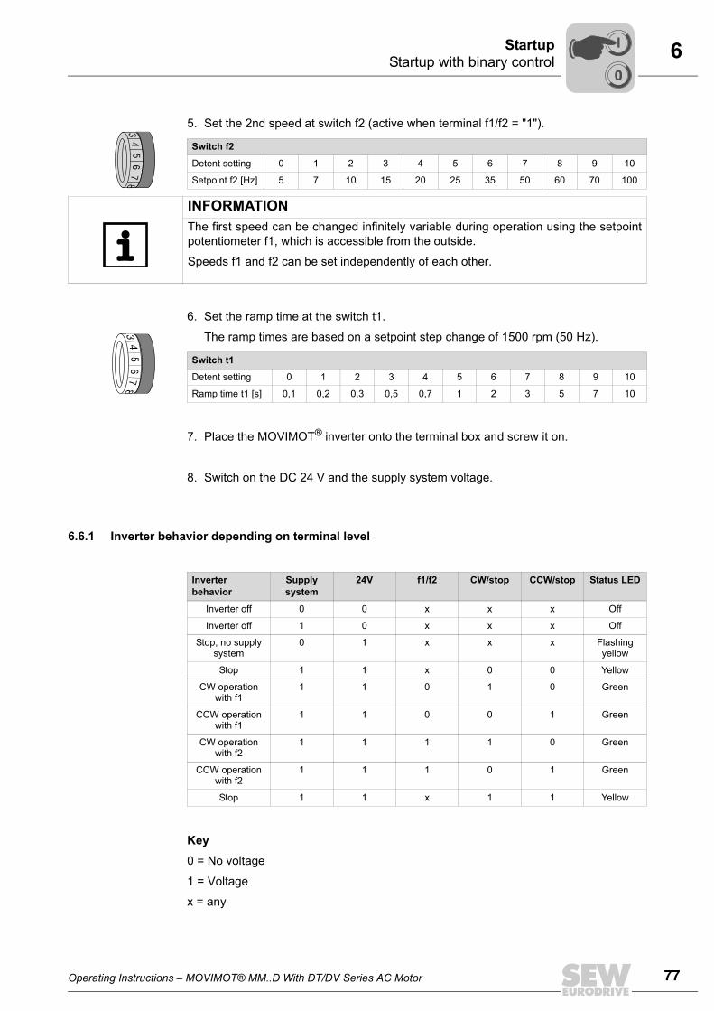
Operating Instructions – MOVIMOT® MM..D With DT/DV Series AC Motor 77
6Startup with binary controlStartup
5. Set the 2nd speed at switch f2 (active when terminal f1/f2 = "1").
6. Set the ramp time at the switch t1.
The ramp times are based on a setpoint step change of 1500 rpm (50 Hz).
7. Place the MOVIMOT® inverter onto the terminal box and screw it on.
8. Switch on the DC 24 V and the supply system voltage.
6.6.1 Inverter behavior depending on terminal level
Key0 = No voltage
1 = Voltage
x = any
Switch f2
Detent setting 0 1 2 3 4 5 6 7 8 9 10
Setpoint f2 [Hz] 5 7 10 15 20 25 35 50 60 70 100
34
56
78
INFORMATIONThe first speed can be changed infinitely variable during operation using the setpointpotentiometer f1, which is accessible from the outside.
Speeds f1 and f2 can be set independently of each other.
Switch t1
Detent setting 0 1 2 3 4 5 6 7 8 9 10
Ramp time t1 [s] 0,1 0,2 0,3 0,5 0,7 1 2 3 5 7 10
34
56
78
Inverterbehavior
Supply system
24V f1/f2 CW/stop CCW/stop Status LED
Inverter off 0 0 x x x Off
Inverter off 1 0 x x x Off
Stop, no supply system
0 1 x x x Flashing yellow
Stop 1 1 x 0 0 Yellow
CW operation with f1
1 1 0 1 0 Green
CCW operation with f1
1 1 0 0 1 Green
CW operation with f2
1 1 1 1 0 Green
CCW operation with f2
1 1 1 0 1 Green
Stop 1 1 x 1 1 Yellow
00
I
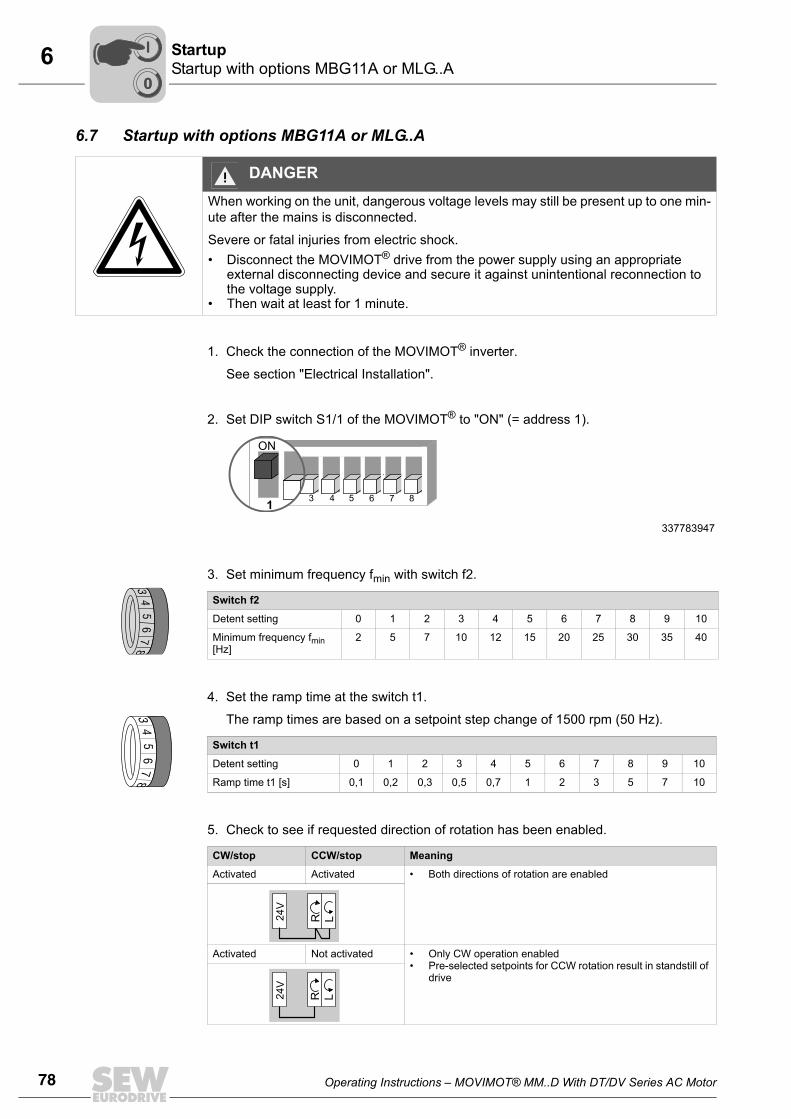
78 Operating Instructions – MOVIMOT® MM..D With DT/DV Series AC Motor
6 Startup with options MBG11A or MLG..AStartup
6.7 Startup with options MBG11A or MLG..A
1. Check the connection of the MOVIMOT® inverter.
See section "Electrical Installation".
2. Set DIP switch S1/1 of the MOVIMOT® to "ON" (= address 1).
3. Set minimum frequency fmin with switch f2.
4. Set the ramp time at the switch t1.
The ramp times are based on a setpoint step change of 1500 rpm (50 Hz).
5. Check to see if requested direction of rotation has been enabled.
DANGERWhen working on the unit, dangerous voltage levels may still be present up to one min-ute after the mains is disconnected.
Severe or fatal injuries from electric shock.• Disconnect the MOVIMOT® drive from the power supply using an appropriate
external disconnecting device and secure it against unintentional reconnection to the voltage supply.
• Then wait at least for 1 minute.
337783947
Switch f2
Detent setting 0 1 2 3 4 5 6 7 8 9 10
Minimum frequency fmin [Hz]
2 5 7 10 12 15 20 25 30 35 40
Switch t1
Detent setting 0 1 2 3 4 5 6 7 8 9 10
Ramp time t1 [s] 0,1 0,2 0,3 0,5 0,7 1 2 3 5 7 10
CW/stop CCW/stop Meaning
Activated Activated • Both directions of rotation are enabled
Activated Not activated • Only CW operation enabled• Pre-selected setpoints for CCW rotation result in standstill of
drive
1
ON
6 7 854321
ON
2
34
56
78
34
56
78
24V
R L
24V
R L
00
I
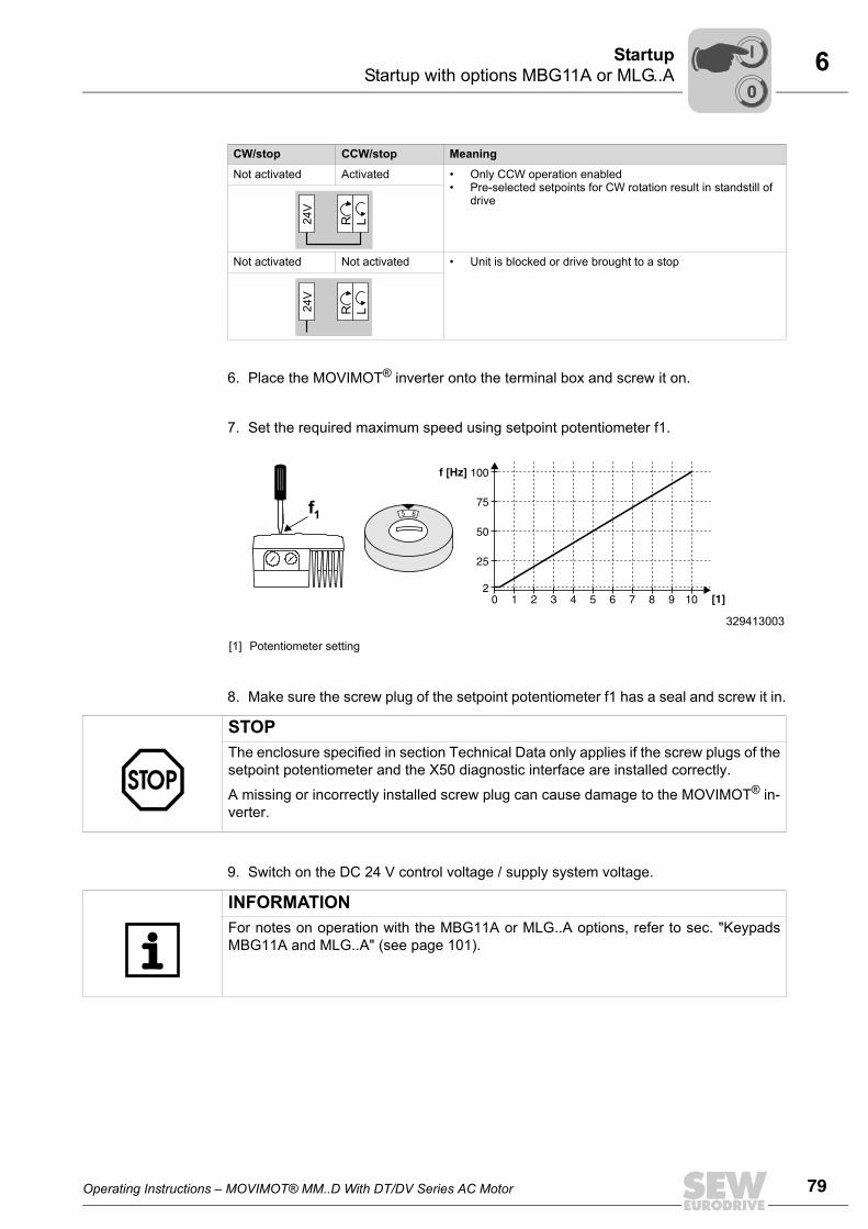
Operating Instructions – MOVIMOT® MM..D With DT/DV Series AC Motor 79
6Startup with options MBG11A or MLG..AStartup
6. Place the MOVIMOT® inverter onto the terminal box and screw it on.
7. Set the required maximum speed using setpoint potentiometer f1.
8. Make sure the screw plug of the setpoint potentiometer f1 has a seal and screw it in.
9. Switch on the DC 24 V control voltage / supply system voltage.
Not activated Activated • Only CCW operation enabled• Pre-selected setpoints for CW rotation result in standstill of
drive
Not activated Not activated • Unit is blocked or drive brought to a stop
329413003
[1] Potentiometer setting
CW/stop CCW/stop Meaning
24V
R L
24V
R L
1 2 3 4 5 6 7 8 9 100
100f [Hz
[1]
]
2
75
25
50
65f1
STOPThe enclosure specified in section Technical Data only applies if the screw plugs of thesetpoint potentiometer and the X50 diagnostic interface are installed correctly.
A missing or incorrectly installed screw plug can cause damage to the MOVIMOT® in-verter.
INFORMATIONFor notes on operation with the MBG11A or MLG..A options, refer to sec. "KeypadsMBG11A and MLG..A" (see page 101).
00
I
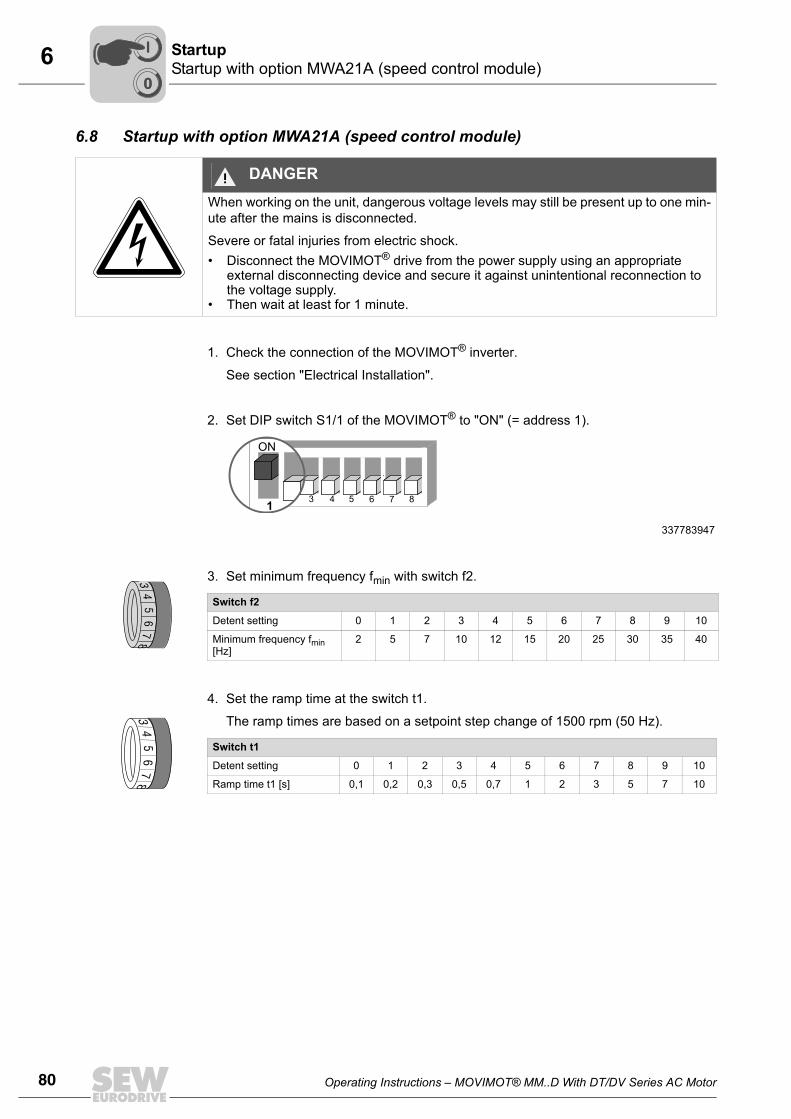
80 Operating Instructions – MOVIMOT® MM..D With DT/DV Series AC Motor
6 Startup with option MWA21A (speed control module)Startup
6.8 Startup with option MWA21A (speed control module)
1. Check the connection of the MOVIMOT® inverter.
See section "Electrical Installation".
2. Set DIP switch S1/1 of the MOVIMOT® to "ON" (= address 1).
3. Set minimum frequency fmin with switch f2.
4. Set the ramp time at the switch t1.
The ramp times are based on a setpoint step change of 1500 rpm (50 Hz).
DANGERWhen working on the unit, dangerous voltage levels may still be present up to one min-ute after the mains is disconnected.
Severe or fatal injuries from electric shock.• Disconnect the MOVIMOT® drive from the power supply using an appropriate
external disconnecting device and secure it against unintentional reconnection to the voltage supply.
• Then wait at least for 1 minute.
337783947
Switch f2
Detent setting 0 1 2 3 4 5 6 7 8 9 10
Minimum frequency fmin [Hz]
2 5 7 10 12 15 20 25 30 35 40
Switch t1
Detent setting 0 1 2 3 4 5 6 7 8 9 10
Ramp time t1 [s] 0,1 0,2 0,3 0,5 0,7 1 2 3 5 7 10
1
ON
6 7 854321
ON
2
34
56
78
34
56
78
00
I
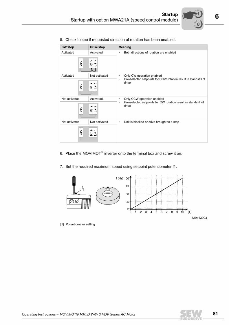
Operating Instructions – MOVIMOT® MM..D With DT/DV Series AC Motor 81
6Startup with option MWA21A (speed control module)Startup
5. Check to see if requested direction of rotation has been enabled.
6. Place the MOVIMOT® inverter onto the terminal box and screw it on.
7. Set the required maximum speed using setpoint potentiometer f1.
CW/stop CCW/stop Meaning
Activated Activated • Both directions of rotation are enabled
Activated Not activated • Only CW operation enabled• Pre-selected setpoints for CCW rotation result in standstill of
drive
Not activated Activated • Only CCW operation enabled• Pre-selected setpoints for CW rotation result in standstill of
drive
Not activated Not activated • Unit is blocked or drive brought to a stop
329413003
[1] Potentiometer setting
24V
R L
24V
R L
24V
R L
24V
R L
1 2 3 4 5 6 7 8 9 100
100f [Hz
[1]
]
2
75
25
50
65f1
00
I
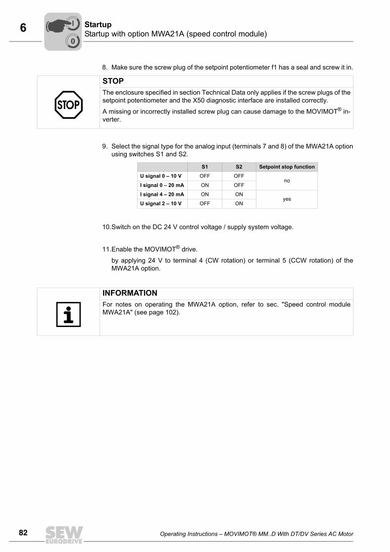
82 Operating Instructions – MOVIMOT® MM..D With DT/DV Series AC Motor
6 Startup with option MWA21A (speed control module)Startup
8. Make sure the screw plug of the setpoint potentiometer f1 has a seal and screw it in.
9. Select the signal type for the analog input (terminals 7 and 8) of the MWA21A optionusing switches S1 and S2.
10.Switch on the DC 24 V control voltage / supply system voltage.
11.Enable the MOVIMOT® drive.
by applying 24 V to terminal 4 (CW rotation) or terminal 5 (CCW rotation) of theMWA21A option.
STOPThe enclosure specified in section Technical Data only applies if the screw plugs of thesetpoint potentiometer and the X50 diagnostic interface are installed correctly.
A missing or incorrectly installed screw plug can cause damage to the MOVIMOT® in-verter.
S1 S2 Setpoint stop function
U signal 0 – 10 V OFF OFFno
I signal 0 – 20 mA ON OFF
I signal 4 – 20 mA ON ONyes
U signal 2 – 10 V OFF ON
INFORMATIONFor notes on operating the MWA21A option, refer to sec. "Speed control moduleMWA21A" (see page 102).
00
I
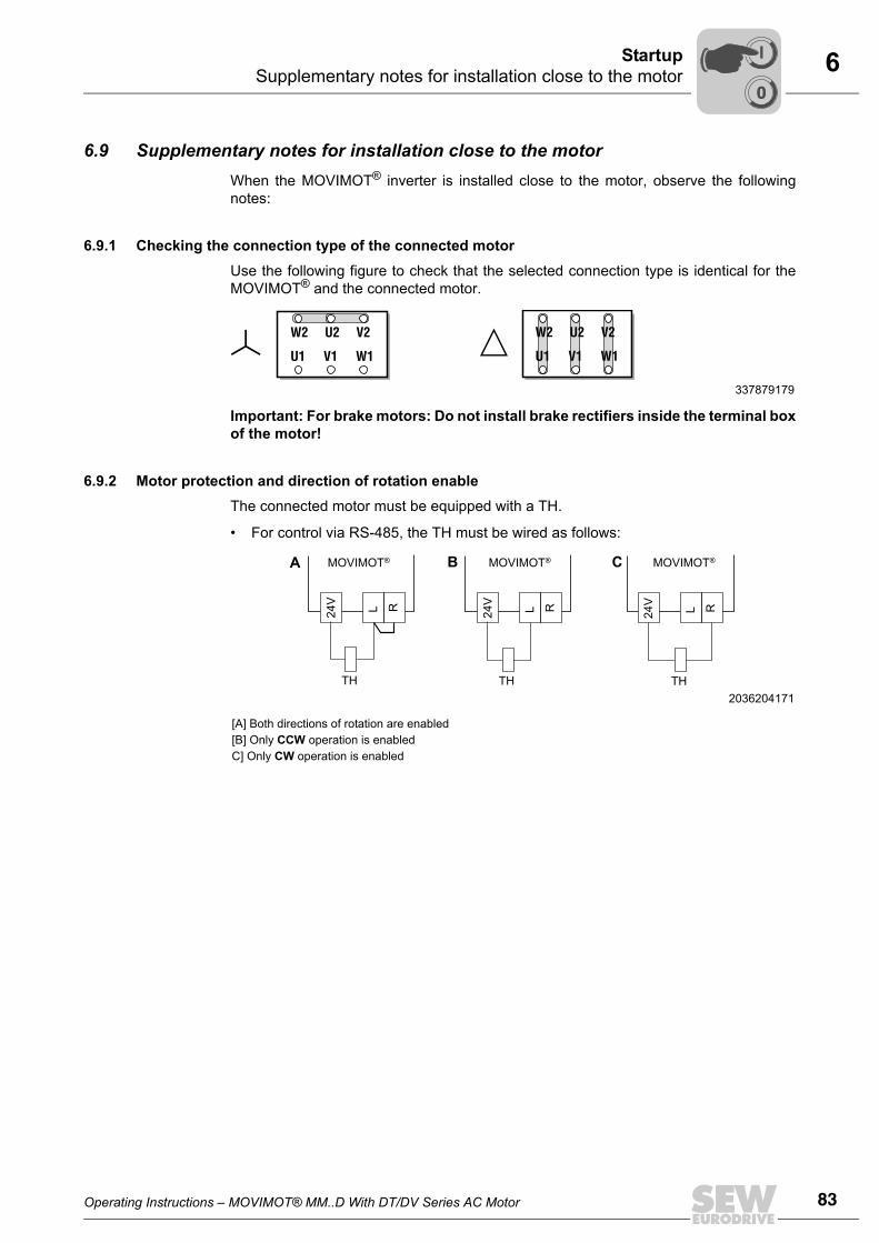
Operating Instructions – MOVIMOT® MM..D With DT/DV Series AC Motor 83
6Supplementary notes for installation close to the motorStartup
6.9 Supplementary notes for installation close to the motor When the MOVIMOT® inverter is installed close to the motor, observe the followingnotes:
6.9.1 Checking the connection type of the connected motorUse the following figure to check that the selected connection type is identical for theMOVIMOT® and the connected motor.
Important: For brake motors: Do not install brake rectifiers inside the terminal boxof the motor!
6.9.2 Motor protection and direction of rotation enableThe connected motor must be equipped with a TH.
• For control via RS-485, the TH must be wired as follows:
337879179
U1 V1 W1
W2 U2 V2
U1 V1 W1
W2 U2 V2
2036204171
[A] Both directions of rotation are enabled[B] Only CCW operation is enabledC] Only CW operation is enabled
24V L R 24V L R 24V L R
TH TH TH
MOVIMOT® MOVIMOT® MOVIMOT®A B C
00
I
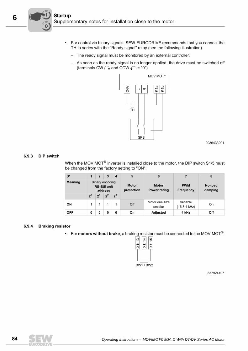
84 Operating Instructions – MOVIMOT® MM..D With DT/DV Series AC Motor
6 Supplementary notes for installation close to the motorStartup
• For control via binary signals, SEW-EURODRIVE recommends that you connect theTH in series with the "Ready signal" relay (see the following illustration).
– The ready signal must be monitored by an external controller.
– As soon as the ready signal is no longer applied, the drive must be switched off(terminals CW and CCW = "0").
6.9.3 DIP switchWhen the MOVIMOT® inverter is installed close to the motor, the DIP switch S1/5 mustbe changed from the factory setting to "ON":
6.9.4 Braking resistor
• For motors without brake, a braking resistor must be connected to the MOVIMOT®.
2036433291
TH
SPS
24V
K1a
K1bL R
MOVIMOT®
S1 1 2 3 4 5
Motorprotection
6
MotorPower rating
7
PWMFrequency
8
No-loaddamping
Meaning Binary encodingRS-485 unit
address
20 21 22 23
ON 1 1 1 1 OffMotor one size
smallerVariable
(16,8,4 kHz)On
OFF 0 0 0 0 On Adjusted 4 kHz Off
337924107
BW1 / BW2
X1:
13
X1:
14
X1:
15
00
I
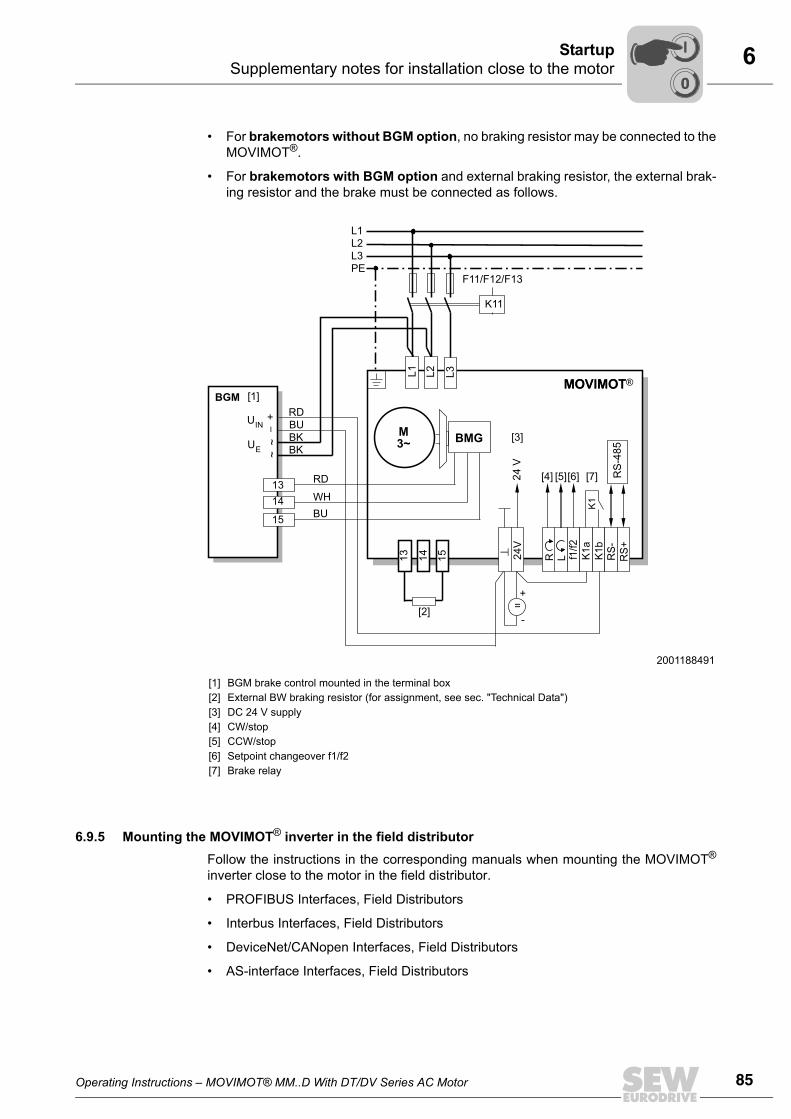
Operating Instructions – MOVIMOT® MM..D With DT/DV Series AC Motor 85
6Supplementary notes for installation close to the motorStartup
• For brakemotors without BGM option, no braking resistor may be connected to theMOVIMOT®.
• For brakemotors with BGM option and external braking resistor, the external brak-ing resistor and the brake must be connected as follows.
6.9.5 Mounting the MOVIMOT® inverter in the field distributorFollow the instructions in the corresponding manuals when mounting the MOVIMOT®
inverter close to the motor in the field distributor.
• PROFIBUS Interfaces, Field Distributors
• Interbus Interfaces, Field Distributors
• DeviceNet/CANopen Interfaces, Field Distributors
• AS-interface Interfaces, Field Distributors
2001188491
[1][2][3][4][5][6][7]
BGM brake control mounted in the terminal box External BW braking resistor (for assignment, see sec. "Technical Data")DC 24 V supplyCW/stop CCW/stop Setpoint changeover f1/f2Brake relay
M3~
L1L2L3PE
K11
F11/F12/F13
K1
RS
-485
13
RD
RD
BKBK
WHBU
BU14 15
L3
24V
R L f1/f2
K1a
K1b
RS-
RS+
=+
-
MOVIMOT
+~
~
[1]
[2]
[3]
[4] [5][6] [7]
BMG
BGMMOVIMOT
24
V
1314
15
L1 L2
_
UIN
UE
00
I
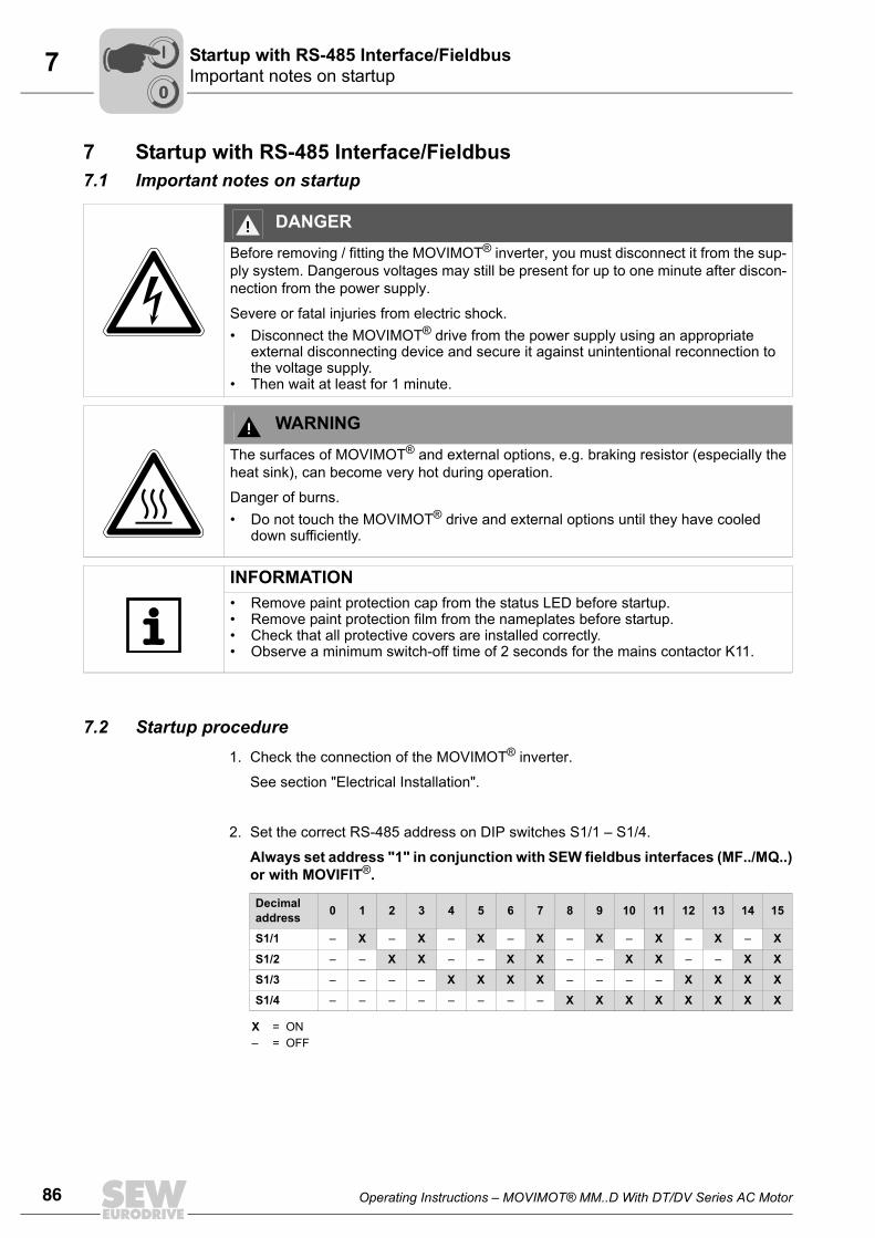
86 Operating Instructions – MOVIMOT® MM..D With DT/DV Series AC Motor
7 Important notes on startupStartup with RS-485 Interface/Fieldbus
7 Startup with RS-485 Interface/Fieldbus7.1 Important notes on startup
7.2 Startup procedure1. Check the connection of the MOVIMOT® inverter.
See section "Electrical Installation".
2. Set the correct RS-485 address on DIP switches S1/1 – S1/4.
Always set address "1" in conjunction with SEW fieldbus interfaces (MF../MQ..)or with MOVIFIT®.
DANGERBefore removing / fitting the MOVIMOT® inverter, you must disconnect it from the sup-ply system. Dangerous voltages may still be present for up to one minute after discon-nection from the power supply.
Severe or fatal injuries from electric shock.• Disconnect the MOVIMOT® drive from the power supply using an appropriate
external disconnecting device and secure it against unintentional reconnection to the voltage supply.
• Then wait at least for 1 minute.
WARNINGThe surfaces of MOVIMOT® and external options, e.g. braking resistor (especially theheat sink), can become very hot during operation.
Danger of burns.• Do not touch the MOVIMOT® drive and external options until they have cooled
down sufficiently.
INFORMATION• Remove paint protection cap from the status LED before startup.• Remove paint protection film from the nameplates before startup.• Check that all protective covers are installed correctly.• Observe a minimum switch-off time of 2 seconds for the mains contactor K11.
Decimal address 0 1 2 3 4 5 6 7 8 9 10 11 12 13 14 15
S1/1 – X – X – X – X – X – X – X – X
S1/2 – – X X – – X X – – X X – – X X
S1/3 – – – – X X X X – – – – X X X X
S1/4 – – – – – – – – X X X X X X X X
X = ON– = OFF
00
I
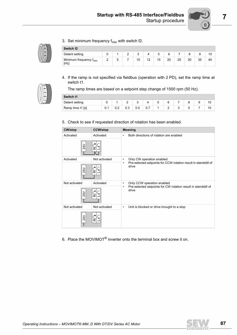
Operating Instructions – MOVIMOT® MM..D With DT/DV Series AC Motor 87
7Startup procedureStartup with RS-485 Interface/Fieldbus
3. Set minimum frequency fmin with switch f2.
4. If the ramp is not specified via fieldbus (operation with 2 PD), set the ramp time atswitch t1.
The ramp times are based on a setpoint step change of 1500 rpm (50 Hz).
5. Check to see if requested direction of rotation has been enabled.
6. Place the MOVIMOT® inverter onto the terminal box and screw it on.
Switch f2
Detent setting 0 1 2 3 4 5 6 7 8 9 10
Minimum frequency fmin [Hz]
2 5 7 10 12 15 20 25 30 35 40
Switch t1
Detent setting 0 1 2 3 4 5 6 7 8 9 10
Ramp time t1 [s] 0.1 0.2 0.3 0.5 0.7 1 2 3 5 7 10
CW/stop CCW/stop Meaning
Activated Activated • Both directions of rotation are enabled
Activated Not activated • Only CW operation enabled• Pre-selected setpoints for CCW rotation result in standstill of
drive
Not activated Activated • Only CCW operation enabled• Pre-selected setpoints for CW rotation result in standstill of
drive
Not activated Not activated • Unit is blocked or drive brought to a stop
34
56
78
34
56
78
24V
R L
24V
R L
24V
R L
24V
R L
00
I
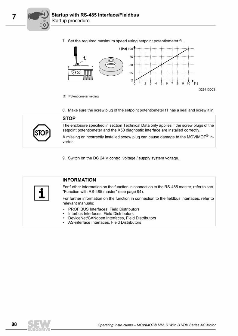
88 Operating Instructions – MOVIMOT® MM..D With DT/DV Series AC Motor
7 Startup procedureStartup with RS-485 Interface/Fieldbus
7. Set the required maximum speed using setpoint potentiometer f1.
8. Make sure the screw plug of the setpoint potentiometer f1 has a seal and screw it in.
9. Switch on the DC 24 V control voltage / supply system voltage.
329413003
[1] Potentiometer setting
1 2 3 4 5 6 7 8 9 100
100f [Hz
[1]
]
2
75
25
50
65f1
STOPThe enclosure specified in section Technical Data only applies if the screw plugs of thesetpoint potentiometer and the X50 diagnostic interface are installed correctly.
A missing or incorrectly installed screw plug can cause damage to the MOVIMOT® in-verter.
INFORMATIONFor further information on the function in connection to the RS-485 master, refer to sec."Function with RS-485 master" (see page 94).
For further information on the function in connection to the fieldbus interfaces, refer torelevant manuals:• PROFIBUS Interfaces, Field Distributors• Interbus Interfaces, Field Distributors• DeviceNet/CANopen Interfaces, Field Distributors• AS-interface Interfaces, Field Distributors
00
I
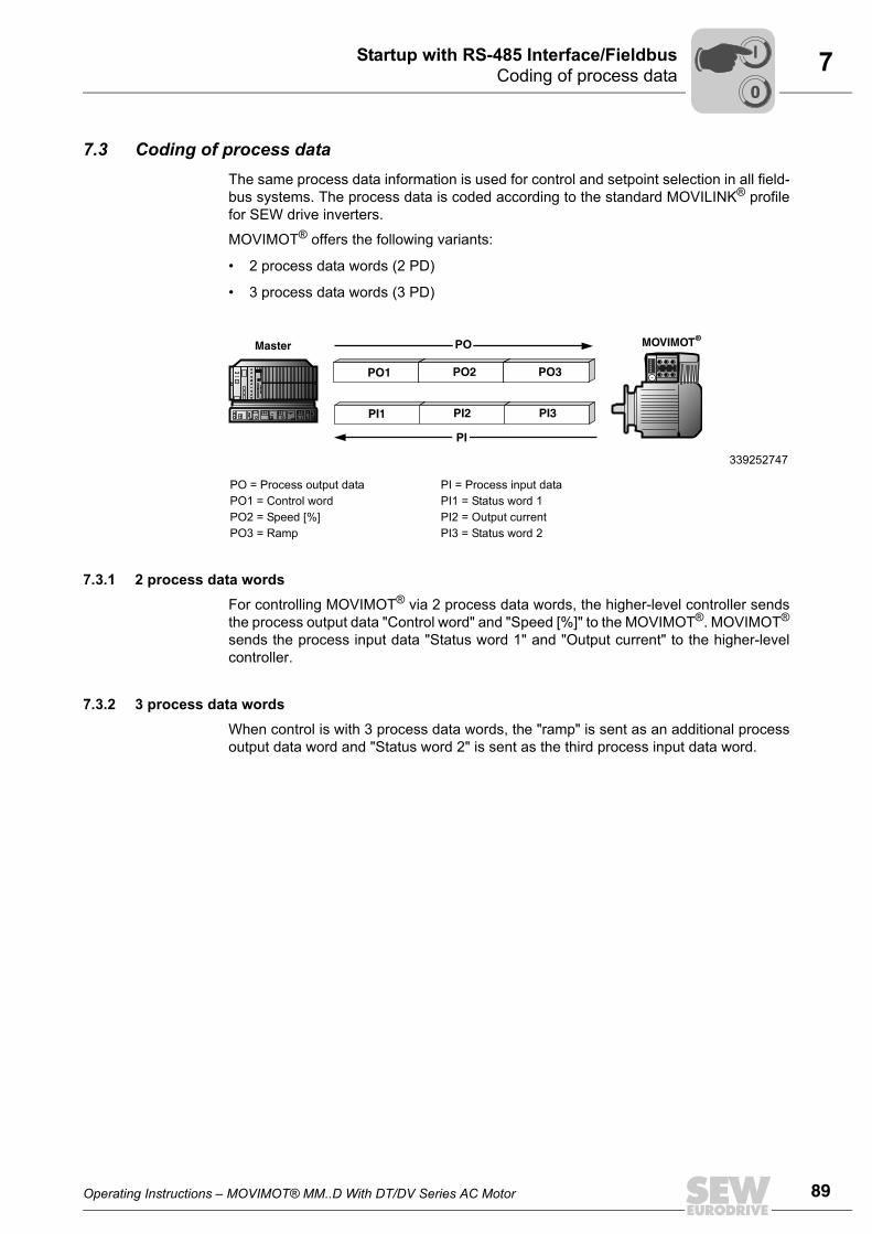
Operating Instructions – MOVIMOT® MM..D With DT/DV Series AC Motor 89
7Coding of process dataStartup with RS-485 Interface/Fieldbus
7.3 Coding of process dataThe same process data information is used for control and setpoint selection in all field-bus systems. The process data is coded according to the standard MOVILINK® profilefor SEW drive inverters.
MOVIMOT® offers the following variants:
• 2 process data words (2 PD)
• 3 process data words (3 PD)
7.3.1 2 process data wordsFor controlling MOVIMOT® via 2 process data words, the higher-level controller sendsthe process output data "Control word" and "Speed [%]" to the MOVIMOT®. MOVIMOT®
sends the process input data "Status word 1" and "Output current" to the higher-levelcontroller.
7.3.2 3 process data wordsWhen control is with 3 process data words, the "ramp" is sent as an additional processoutput data word and "Status word 2" is sent as the third process input data word.
339252747
PO = Process output data PI = Process input dataPO1 = Control word PI1 = Status word 1PO2 = Speed [%] PI2 = Output currentPO3 = Ramp PI3 = Status word 2
MOVIMOT®
PO1 PO2 PO3
Master
PI1 PI2 PI3
PO
PI
00
I
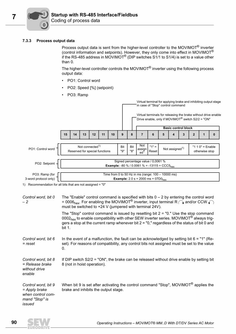
90 Operating Instructions – MOVIMOT® MM..D With DT/DV Series AC Motor
7 Coding of process dataStartup with RS-485 Interface/Fieldbus
7.3.3 Process output data
Process output data is sent from the higher-level controller to the MOVIMOT® inverter(control information and setpoints). However, they only come into effect in MOVIMOT®
if the RS-485 address in MOVIMOT® (DIP switches S1/1 to S1/4) is set to a value otherthan 0.
The higher-level controller controls the MOVIMOT® inverter using the following processoutput data:
• PO1: Control word
• PO2: Speed [%] (setpoint)
• PO3: Ramp
Control word, bit 0 – 2
The "Enable" control command is specified with bits 0 – 2 by entering the control word= 0006hex. For enabling the MOVIMOT® inverter, input terminal R and/or CCW must be switched to +24 V (jumpered with terminal 24V).
The "Stop" control command is issued by resetting bit 2 = "0." Use the stop command0002hex to enable compatibility with other SEW inverter series. MOVIMOT® always trig-gers a stop at the current ramp whenever bit 2 = "0," regardless of the status of bit 0 andbit 1.
Control word, bit 6 = reset
In the event of a malfunction, the fault can be acknowledged by setting bit 6 = "1" (Re-set). For reasons of compatibility, any control bits not assigned must be set to the value0.
Control word, bit 8 = Release brake without drive enable
If DIP switch S2/2 = "ON", the brake can be released without drive enable by setting bit8 (not in hoist operation).
Control word, bit 9 = Apply brake when control com-mand "Stop" is issued
When bit 9 is set after activating the control command "Stop", MOVIMOT® applies thebrake and inhibits the output stage.
Virtual terminal for applying brake and inhibiting output stage in case of "Stop" control command
Virtual terminals for releasing the brake without drive enableDrive enable, only if MOVIMOT® switch S2/2 = "ON"
Basic control block
15 14 13 12 11 10 9 8 7 6 5 4 3 2 1 0
PO1: Control wordNot connected1)
Reserved for special functionsBit"9"
Bit"8"
Not assign
ed1
"1" = Reset
Not assigned1) "1 1 0" = Enableotherwise stop
PO2: SetpointSigned percentage value / 0,0061 %
Example: -80 % / 0.0061 % = -13115 = CCC5hex
PO3: Ramp (for3-word protocol only)
Time from 0 to 50 Hz in ms (range: 100 – 10000 ms)Example: 2.0 s = 2000 ms = 07D0hex
1) Recommendation for all bits that are not assigned = "0"
00
I
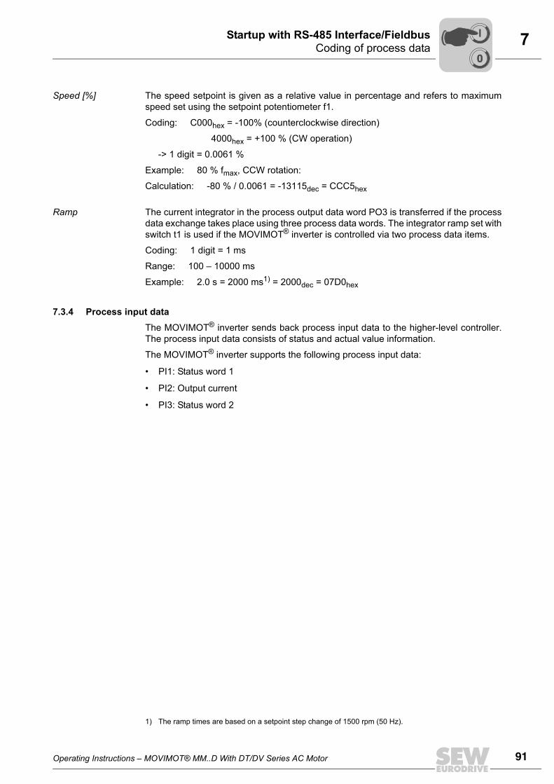
Operating Instructions – MOVIMOT® MM..D With DT/DV Series AC Motor 91
7Coding of process dataStartup with RS-485 Interface/Fieldbus
Speed [%] The speed setpoint is given as a relative value in percentage and refers to maximumspeed set using the setpoint potentiometer f1.
Coding: C000hex = -100% (counterclockwise direction)
4000hex = +100 % (CW operation)
-> 1 digit = 0.0061 %
Example: 80 % fmax, CCW rotation:
Calculation: -80 % / 0.0061 = -13115dec = CCC5hex
Ramp The current integrator in the process output data word PO3 is transferred if the processdata exchange takes place using three process data words. The integrator ramp set withswitch t1 is used if the MOVIMOT® inverter is controlled via two process data items.
Coding: 1 digit = 1 ms
Range: 100 – 10000 ms
Example: 2.0 s = 2000 ms1) = 2000dec = 07D0hex
7.3.4 Process input dataThe MOVIMOT® inverter sends back process input data to the higher-level controller.The process input data consists of status and actual value information.
The MOVIMOT® inverter supports the following process input data:
• PI1: Status word 1
• PI2: Output current
• PI3: Status word 2
1) The ramp times are based on a setpoint step change of 1500 rpm (50 Hz).
00
I
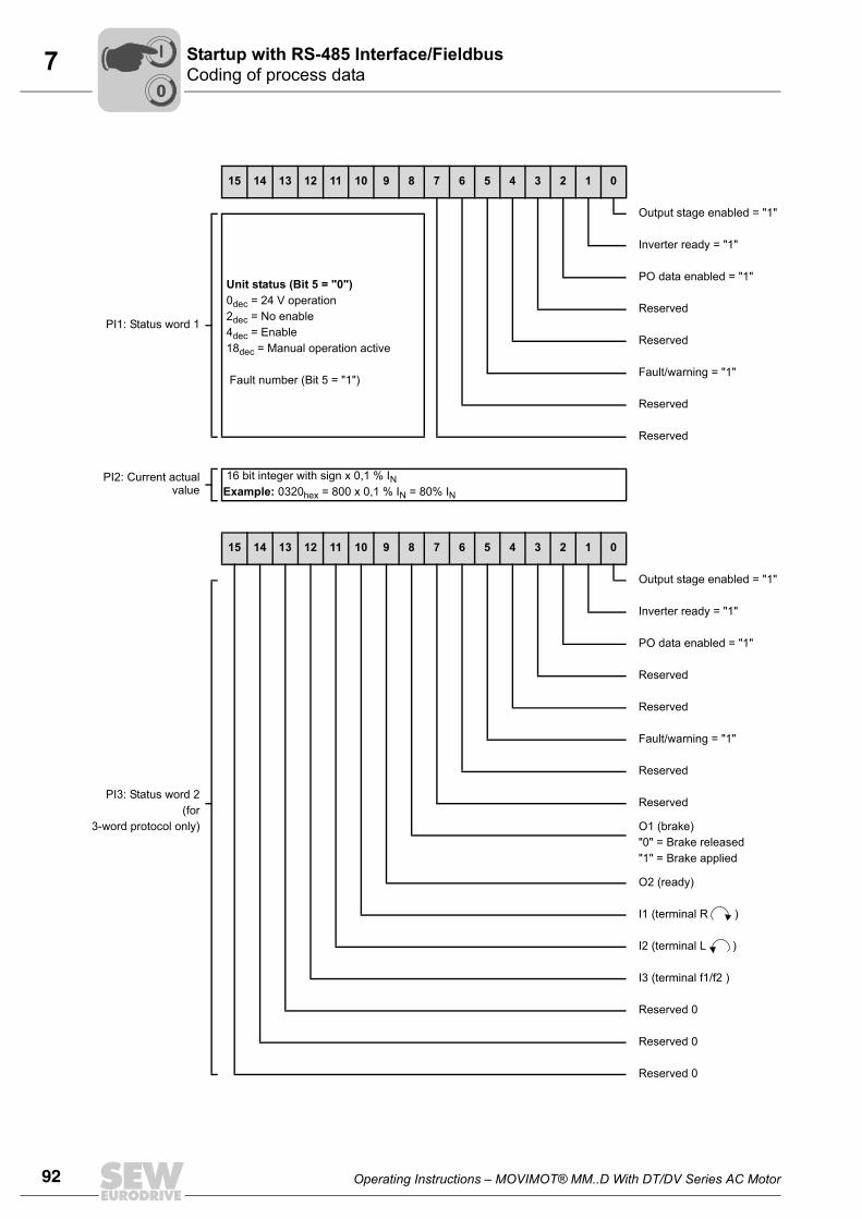
92 Operating Instructions – MOVIMOT® MM..D With DT/DV Series AC Motor
7 Coding of process dataStartup with RS-485 Interface/Fieldbus
15 14 13 12 11 10 9 8 7 6 5 4 3 2 1 0
Output stage enabled = "1"
PI1: Status word 1
Unit status (Bit 5 = "0") 0dec = 24 V operation 2dec = No enable 4dec = Enable 18dec = Manual operation active
Fault number (Bit 5 = "1")
Inverter ready = "1"
PO data enabled = "1"
Reserved
Reserved
Fault/warning = "1"
Reserved
Reserved
PI2: Current actualvalue
16 bit integer with sign x 0,1 % INExample: 0320hex = 800 x 0,1 % IN = 80% IN
PI3: Status word 2(for
3-word protocol only)
15 14 13 12 11 10 9 8 7 6 5 4 3 2 1 0
Output stage enabled = "1"
Inverter ready = "1"
PO data enabled = "1"
Reserved
Reserved
Fault/warning = "1"
Reserved
Reserved
O1 (brake) "0" = Brake released"1" = Brake applied
O2 (ready)
I1 (terminal R )
I2 (terminal L )
I3 (terminal f1/f2 )
Reserved 0
Reserved 0
Reserved 0
00
I
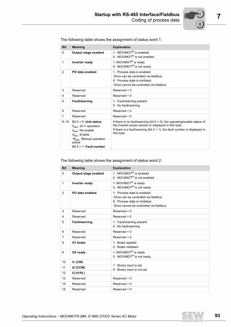
Operating Instructions – MOVIMOT® MM..D With DT/DV Series AC Motor 93
7Coding of process dataStartup with RS-485 Interface/Fieldbus
The following table shows the assignment of status word 1:
The following table shows the assignment of status word 2:
Bit Meaning Explanation
0 Output stage enabled 1: MOVIMOT® is enabled0: MOVIMOT® is not enabled
1 Inverter ready 1: MOVIMOT® is ready0: MOVIMOT® is not ready
2 PO data enabled 1: Process data is enabled; Drive can be controlled via fieldbus0: Process data is inhibited; Drive cannot be controlled via fieldbus
3 Reserved Reserved = 0
4 Reserved Reserved = 0
5 Fault/warning 1: Fault/warning present0: No fault/warning
6 Reserved Reserved = 0
7 Reserved Reserved = 0
8–15 Bit 5 = 0: Unit status0dec: 24 V operation2dec: No enable4dec: Enable18dec: Manual operation activeBit 5 = 1: Fault number
If there is no fault/warning (bit 5 = 0), the operating/enable status of the inverter power section is displayed in this byte.If there is a fault/warning (bit 5 = 1), the fault number is displayed in this byte.
Bit Meaning Explanation
0 Output stage enabled 1: MOVIMOT® is enabled0: MOVIMOT® is not enabled
1 Inverter ready 1: MOVIMOT® is ready0: MOVIMOT® is not ready
2 PO data enabled 1: Process data is enabled; Drive can be controlled via fieldbus0: Process data is inhibited; Drive cannot be controlled via fieldbus
3 Reserved Reserved = 0
4 Reserved Reserved = 0
5 Fault/warning 1: Fault/warning present0: No fault/warning
6 Reserved Reserved = 0
7 Reserved Reserved = 0
8 O1 brake 1: Brake applied0: Brake released
9 O2 ready 1: MOVIMOT® is ready0: MOVIMOT® is not ready
10 I1 (CW)1: Binary input is set0: Binary input is not set
11 I2 (CCW)
12 I3 (f1/f2 )
13 Reserved Reserved = 0
14 Reserved Reserved = 0
15 Reserved Reserved = 0
00
I
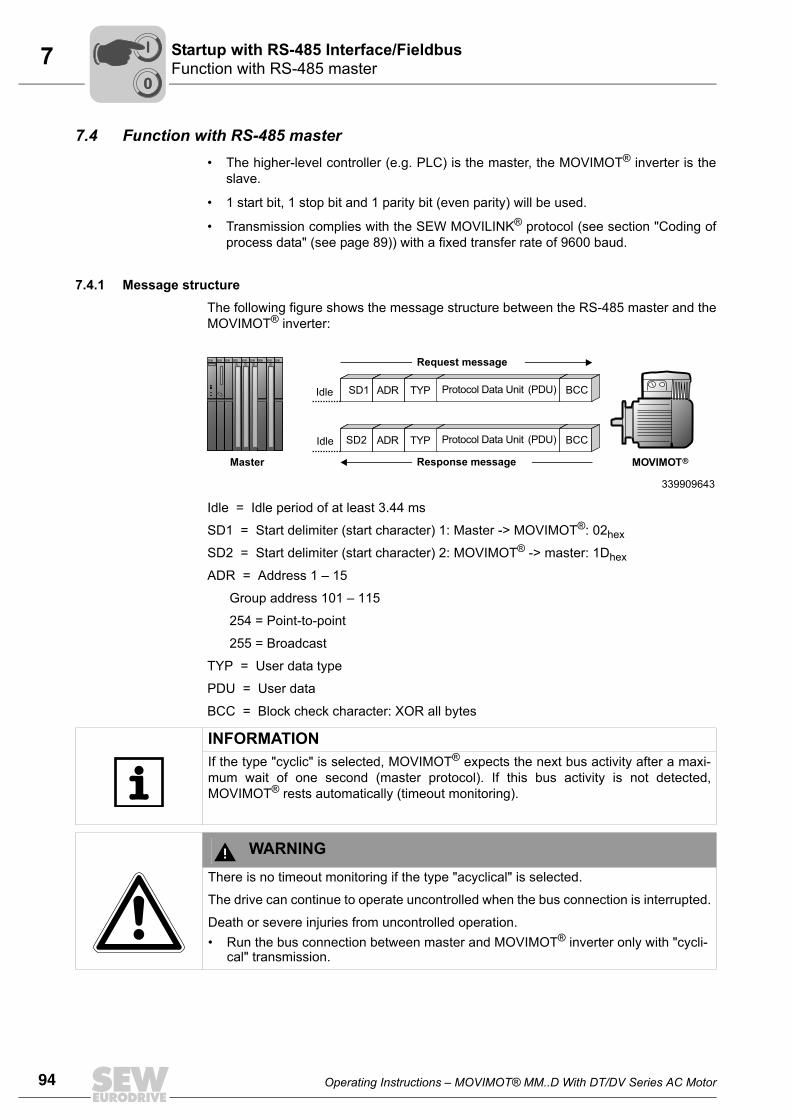
94 Operating Instructions – MOVIMOT® MM..D With DT/DV Series AC Motor
7 Function with RS-485 masterStartup with RS-485 Interface/Fieldbus
7.4 Function with RS-485 master• The higher-level controller (e.g. PLC) is the master, the MOVIMOT® inverter is the
slave.
• 1 start bit, 1 stop bit and 1 parity bit (even parity) will be used.
• Transmission complies with the SEW MOVILINK® protocol (see section "Coding ofprocess data" (see page 89)) with a fixed transfer rate of 9600 baud.
7.4.1 Message structureThe following figure shows the message structure between the RS-485 master and theMOVIMOT® inverter:
Idle = Idle period of at least 3.44 ms
SD1 = Start delimiter (start character) 1: Master -> MOVIMOT®: 02hex
SD2 = Start delimiter (start character) 2: MOVIMOT® -> master: 1Dhex
ADR = Address 1 – 15
Group address 101 – 115
254 = Point-to-point
255 = Broadcast
TYP = User data type
PDU = User data
BCC = Block check character: XOR all bytes
339909643
SD2 ADR TYP Protocol Data Unit (PDU) BCC
SD1 ADR TYP Protocol Data Unit (PDU) BCC
Request message
Response message MOVIMOT®Master
Idle
Idle
INFORMATIONIf the type "cyclic" is selected, MOVIMOT® expects the next bus activity after a maxi-mum wait of one second (master protocol). If this bus activity is not detected,MOVIMOT® rests automatically (timeout monitoring).
WARNINGThere is no timeout monitoring if the type "acyclical" is selected.
The drive can continue to operate uncontrolled when the bus connection is interrupted.
Death or severe injuries from uncontrolled operation.• Run the bus connection between master and MOVIMOT® inverter only with "cycli-
cal" transmission.
00
I
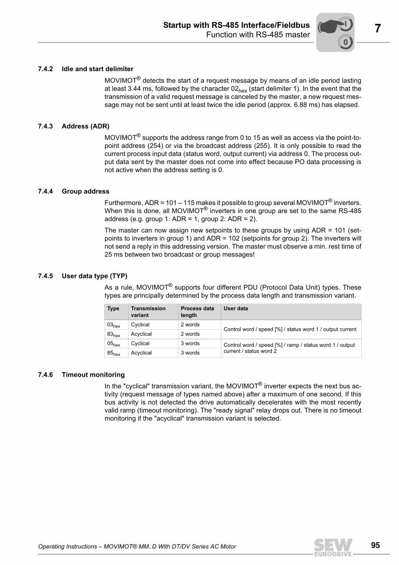
Operating Instructions – MOVIMOT® MM..D With DT/DV Series AC Motor 95
7Function with RS-485 masterStartup with RS-485 Interface/Fieldbus
7.4.2 Idle and start delimiter
MOVIMOT® detects the start of a request message by means of an idle period lastingat least 3.44 ms, followed by the character 02hex (start delimiter 1). In the event that thetransmission of a valid request message is canceled by the master, a new request mes-sage may not be sent until at least twice the idle period (approx. 6.88 ms) has elapsed.
7.4.3 Address (ADR) MOVIMOT® supports the address range from 0 to 15 as well as access via the point-to-point address (254) or via the broadcast address (255). It is only possible to read thecurrent process input data (status word, output current) via address 0. The process out-put data sent by the master does not come into effect because PO data processing isnot active when the address setting is 0.
7.4.4 Group addressFurthermore, ADR = 101 – 115 makes it possible to group several MOVIMOT® inverters.When this is done, all MOVIMOT® inverters in one group are set to the same RS-485address (e.g. group 1: ADR = 1, group 2: ADR = 2).
The master can now assign new setpoints to these groups by using ADR = 101 (set-points to inverters in group 1) and ADR = 102 (setpoints for group 2). The inverters willnot send a reply in this addressing version. The master must observe a min. rest time of25 ms between two broadcast or group messages!
7.4.5 User data type (TYP)As a rule, MOVIMOT® supports four different PDU (Protocol Data Unit) types. Thesetypes are principally determined by the process data length and transmission variant.
7.4.6 Timeout monitoringIn the "cyclical" transmission variant, the MOVIMOT® inverter expects the next bus ac-tivity (request message of types named above) after a maximum of one second. If thisbus activity is not detected the drive automatically decelerates with the most recentlyvalid ramp (timeout monitoring). The "ready signal" relay drops out. There is no timeoutmonitoring if the "acyclical" transmission variant is selected.
Type Transmission variant
Process data length
User data
03hex Cyclical 2 wordsControl word / speed [%] / status word 1 / output current
83hex Acyclical 2 words
05hex Cyclical 3 words Control word / speed [%] / ramp / status word 1 / output current / status word 285hex Acyclical 3 words
00
I
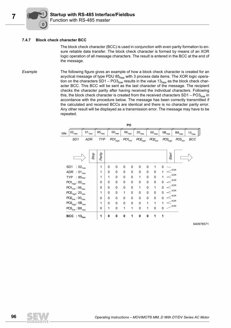
96 Operating Instructions – MOVIMOT® MM..D With DT/DV Series AC Motor
7 Function with RS-485 masterStartup with RS-485 Interface/Fieldbus
7.4.7 Block check character BCC
The block check character (BCC) is used in conjunction with even parity formation to en-sure reliable data transfer. The block check character is formed by means of an XORlogic operation of all message characters. The result is entered in the BCC at the end ofthe message.
Example The following figure gives an example of how a block check character is created for anacyclical message of type PDU 85hex with 3 process data items. The XOR logic opera-tion on the characters SD1 – PO3low results in the value 13hex as the block check char-acter BCC. This BCC will be sent as the last character of the message. The recipientchecks the character parity after having received the individual characters. Followingthis, the block check character is created from the received characters SD1 – PO3low inaccordance with the procedure below. The message has been correctly transmitted ifthe calculated and received BCCs are identical and there is no character parity error.Any other result will be displayed as a transmission error. The message may have to berepeated.
640978571
1 0 0 0 0 0 0 011 0 0 0 0 0 0 101 1 0 0 0 1 0 100 0 0 0 0 0 0 000 0 0 0 0 1 0 011 0 0 1 0 0 0 000 0 0 0 0 0 0 001 0 0 0 0 0 1 110 1 0 1 1 0 1 00
1 0 0 0 1 0 0 11
TYPADRSD1 PO1high PO1low PO2high PO2low PO3high PO3low BCC
Parit
y
Stop
Star
tSD1 02hex
ADR 01hex
TYP
::: 85hex
BCC : 13hex
XOR
XOR
XOR
XOR
XOR
XOR
XOR
XOR
Idle 02hex 01hex 85hex 00hex 06hex 20hex 00hex 0Bhex B8hex 13hex
PO
PO1high: 00hex
PO1low : 06hex
PO2high: 20hex
PO2low : 00hex
PO3high: 0Bhex
PO3low : B8hex
00
I
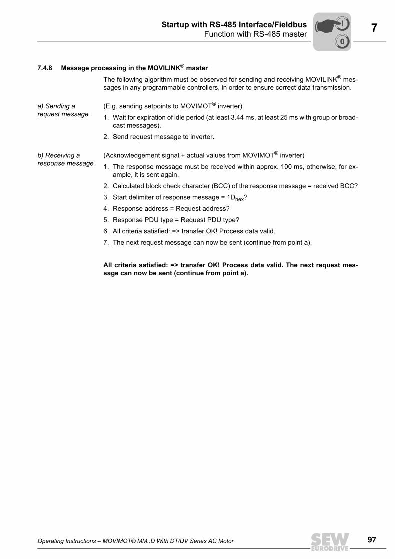
Operating Instructions – MOVIMOT® MM..D With DT/DV Series AC Motor 97
7Function with RS-485 masterStartup with RS-485 Interface/Fieldbus
7.4.8 Message processing in the MOVILINK® master
The following algorithm must be observed for sending and receiving MOVILINK® mes-sages in any programmable controllers, in order to ensure correct data transmission.
a) Sending a request message
(E.g. sending setpoints to MOVIMOT® inverter)
1. Wait for expiration of idle period (at least 3.44 ms, at least 25 ms with group or broad-cast messages).
2. Send request message to inverter.
b) Receiving a response message
(Acknowledgement signal + actual values from MOVIMOT® inverter)
1. The response message must be received within approx. 100 ms, otherwise, for ex-ample, it is sent again.
2. Calculated block check character (BCC) of the response message = received BCC?
3. Start delimiter of response message = 1Dhex?
4. Response address = Request address?
5. Response PDU type = Request PDU type?
6. All criteria satisfied: => transfer OK! Process data valid.
7. The next request message can now be sent (continue from point a).
All criteria satisfied: => transfer OK! Process data valid. The next request mes-sage can now be sent (continue from point a).
00
I
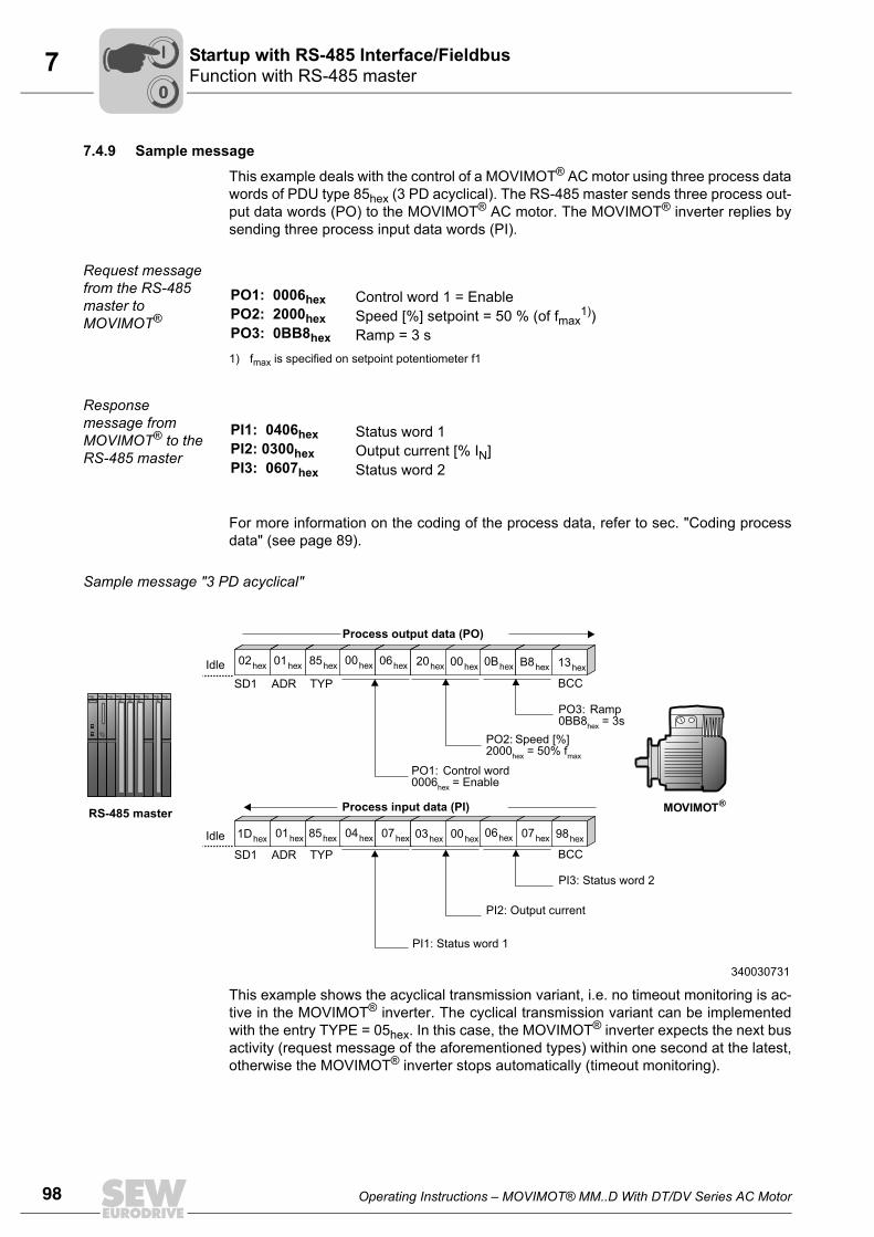
98 Operating Instructions – MOVIMOT® MM..D With DT/DV Series AC Motor
7 Function with RS-485 masterStartup with RS-485 Interface/Fieldbus
7.4.9 Sample message
This example deals with the control of a MOVIMOT® AC motor using three process datawords of PDU type 85hex (3 PD acyclical). The RS-485 master sends three process out-put data words (PO) to the MOVIMOT® AC motor. The MOVIMOT® inverter replies bysending three process input data words (PI).
Request message from the RS-485 master to MOVIMOT®
Response message from MOVIMOT® to the RS-485 master
For more information on the coding of the process data, refer to sec. "Coding processdata" (see page 89).
Sample message "3 PD acyclical"
This example shows the acyclical transmission variant, i.e. no timeout monitoring is ac-tive in the MOVIMOT® inverter. The cyclical transmission variant can be implementedwith the entry TYPE = 05hex. In this case, the MOVIMOT® inverter expects the next busactivity (request message of the aforementioned types) within one second at the latest,otherwise the MOVIMOT® inverter stops automatically (timeout monitoring).
PO1: 0006hex Control word 1 = EnablePO2: 2000hex Speed [%] setpoint = 50 % (of fmax
1))
1) fmax is specified on setpoint potentiometer f1
PO3: 0BB8hex Ramp = 3 s
PI1: 0406hex Status word 1PI2: 0300hex Output current [% IN]PI3: 0607hex Status word 2
TYP
TYP
ADR
ADR
SD1
SD1
BCC
BCC
MOVIMOT®
Idle
Idle
02hex 01hex 85hex 00hex 06hex 20hex 00hex 0Bhex B8hex 13hex
1Dhex 01hex 85hex 04hex 07hex 03hex 00hex 06hex 07hex 98hex
RS-485 master
PO1: Control word0006 = Enablehex
PI1: Status word 1
PO2: Speed [%] 2000 = 50% fhex max
PI2: Output current
PO3: Ramp0BB8 = 3shex
PI3: Status word 2
Process output data (PO)
Process input data (PI)
340030731
00
I
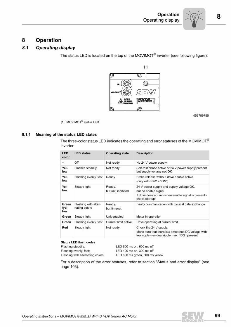
Operating Instructions – MOVIMOT® MM..D With DT/DV Series AC Motor 99
8Operating displayOperation
8 Operation8.1 Operating display
The status LED is located on the top of the MOVIMOT® inverter (see following figure).
8.1.1 Meaning of the status LED statesThe three-color status LED indicates the operating and error statuses of the MOVIMOT®
inverter.
For a description of the error statuses, refer to section "Status and error display" (seepage 103).
459759755
[1] MOVIMOT® status LED
[1]
LED color
LED status Operating state Description
– Off Not ready No 24 V power supply
Yel-low
Flashes steadily Not ready Self-test phase active or 24 V power supply present but supply voltage not OK
Yel-low
Flashing evenly, fast Ready Brake release without drive enable active(only with S2/2 = "ON")
Yel-low
Steady light Ready, but unit inhibited
24 V power supply and supply voltage OK, but no enable signalIf drive does not run when enable signal is present - check startup!
Green/yel-low
Flashing with alter-nating colors
Ready, but timeout
Faulty communication with cyclical data exchange
Green Steady light Unit enabled Motor in operation
Green Flashing evenly, fast Current limit active Drive operating at current limit
Red Steady light Not ready Check the 24 V supply.Make sure that there is a smoothed DC voltage with low ripple (residual ripple max. 13%) present
Status LED flash codesFlashing steadily: LED 600 ms on, 600 ms offFlashing evenly, fast: LED 100 ms on, 300 ms offFlashing with alternating colors: LED 600 ms green, 600 ms yellow
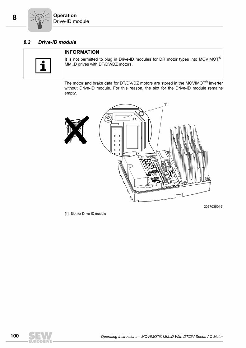
100 Operating Instructions – MOVIMOT® MM..D With DT/DV Series AC Motor
8 Drive-ID moduleOperation
8.2 Drive-ID module
The motor and brake data for DT/DV/DZ motors are stored in the MOVIMOT® inverterwithout Drive-ID module. For this reason, the slot for the Drive-ID module remainsempty.
INFORMATIONIt is not permitted to plug in Drive-ID modules for DR motor types into MOVIMOT®
MM..D drives with DT/DV/DZ motors.
2037035019
[1] Slot for Drive-ID module
[1]
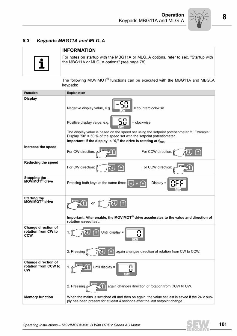
Operating Instructions – MOVIMOT® MM..D With DT/DV Series AC Motor 101
8Keypads MBG11A and MLG..AOperation
8.3 Keypads MBG11A and MLG..A
The following MOVIMOT® functions can be executed with the MBG11A and MBG..Akeypads:
INFORMATIONFor notes on startup with the MBG11A or MLG..A options, refer to sec. "Startup withthe MBG11A or MLG..A options" (see page 78).
Function Explanation
Display
Negative display value, e.g. = counterclockwise
Positive display value, e.g. = clockwise
The display value is based on the speed set using the setpoint potentiometer f1. Example: Display "50" = 50 % of the speed set with the setpoint potentiometer.Important: If the display is "0," the drive is rotating at fmin.
Increase the speedFor CW direction: For CCW direction:
Reducing the speedFor CW direction: For CCW direction:
Stopping the MOVIMOT® drive Pressing both keys at the same time: Display =
Starting the MOVIMOT® drive or
Important: After enable, the MOVIMOT® drive accelerates to the value and direction of rotation saved last.
Change direction of rotation from CW to CCW
1. Until display =
2. Pressing again changes direction of rotation from CW to CCW.
Change direction of rotation from CCW to CW
1. Until display =
2. Pressing again changes direction of rotation from CCW to CW.
Memory function When the mains is switched off and then on again, the value set last is saved if the 24 V sup-ply has been present for at least 4 seconds after the last setpoint change.
+
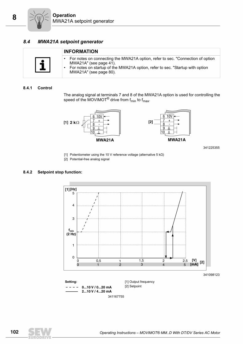
102 Operating Instructions – MOVIMOT® MM..D With DT/DV Series AC Motor
8 MWA21A setpoint generatorOperation
8.4 MWA21A setpoint generator
8.4.1 ControlThe analog signal at terminals 7 and 8 of the MWA21A option is used for controlling thespeed of the MOVIMOT® drive from fmin to fmax.
8.4.2 Setpoint stop function:
INFORMATION• For notes on connecting the MWA21A option, refer to sec. "Connection of option
MWA21A" (see page 41).• For notes on startup of the MWA21A option, refer to sec. "Startup with option
MWA21A" (see page 80).
341225355
[1][2]
Potentiometer using the 10 V reference voltage (alternative 5 kΩ)Potential-free analog signal
6 10V7 +8 -9
10
6 10V7 +8 -9
10
MWA21A MWA21A
2 k[1] [2]
341098123
Setting: [1] Output frequency[2] Setpoint
341167755
0 0,5 1 1,5 2 2,50 1 2 3 4 5
[V][mA]
f(2 Hz)
min
[Hz]5
4
3
1
0
[1]
[2]
0...10 V / 0...20 mA2...10 V / 4...20 mA
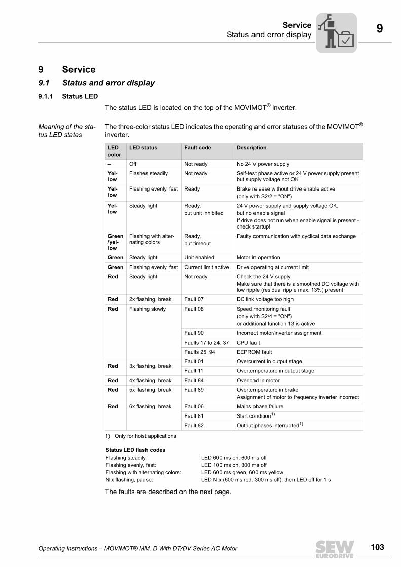
Operating Instructions – MOVIMOT® MM..D With DT/DV Series AC Motor 103
9Status and error displayService
9 Service9.1 Status and error display9.1.1 Status LED
The status LED is located on the top of the MOVIMOT® inverter.
Meaning of the sta-tus LED states
The three-color status LED indicates the operating and error statuses of the MOVIMOT®
inverter.
The faults are described on the next page.
LED color
LED status Fault code Description
– Off Not ready No 24 V power supply
Yel-low
Flashes steadily Not ready Self-test phase active or 24 V power supply present but supply voltage not OK
Yel-low
Flashing evenly, fast Ready Brake release without drive enable active(only with S2/2 = "ON")
Yel-low
Steady light Ready, but unit inhibited
24 V power supply and supply voltage OK, but no enable signalIf drive does not run when enable signal is present - check startup!
Green/yel-low
Flashing with alter-nating colors
Ready, but timeout
Faulty communication with cyclical data exchange
Green Steady light Unit enabled Motor in operation
Green Flashing evenly, fast Current limit active Drive operating at current limit
Red Steady light Not ready Check the 24 V supply.Make sure that there is a smoothed DC voltage with low ripple (residual ripple max. 13%) present
Red 2x flashing, break Fault 07 DC link voltage too high
Red Flashing slowly Fault 08 Speed monitoring fault (only with S2/4 = "ON")or additional function 13 is active
Fault 90 Incorrect motor/inverter assignment
Faults 17 to 24, 37 CPU fault
Faults 25, 94 EEPROM fault
Red 3x flashing, breakFault 01 Overcurrent in output stage
Fault 11 Overtemperature in output stage
Red 4x flashing, break Fault 84 Overload in motor
Red 5x flashing, break Fault 89 Overtemperature in brakeAssignment of motor to frequency inverter incorrect
Red 6x flashing, break Fault 06 Mains phase failure
Fault 81 Start condition1)
Fault 82 Output phases interrupted1)
1) Only for hoist applications
Status LED flash codesFlashing steadily: LED 600 ms on, 600 ms offFlashing evenly, fast: LED 100 ms on, 300 ms offFlashing with alternating colors: LED 600 ms green, 600 ms yellowN x flashing, pause: LED N x (600 ms red, 300 ms off), then LED off for 1 s
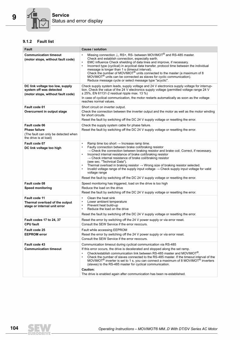
104 Operating Instructions – MOVIMOT® MM..D With DT/DV Series AC Motor
9 Status and error displayService
9.1.2 Fault list
Fault Cause / solution
Communication timeout (motor stops, without fault code)
• Missing connection ⊥, RS+, RS- between MOVIMOT® and RS-485 master. Check and establish connection, especially earth.
• EMC influence Check shielding of data lines and improve, if necessary.• Incorrect type (cyclical) in acyclical data transfer, protocol time between the individual
message is longer than 1 s (timeout interval).Check the number of MOVIMOT® units connected to the master (a maximum of 8 MOVIMOT® units can be connected as slaves for cyclic communication).Reduce message cycle or select message type "acyclic".
DC link voltage too low, supply system off was detected(motor stops, without fault code)
Check supply system leads, supply voltage and 24 V electronics supply voltage for interrup-tion. Check the value of the 24 V electronics supply voltage (permitted voltage range 24 V ± 25%, EN 61131-2 residual ripple max. 13 %)In case of cyclical communication, the motor restarts automatically as soon as the voltage reaches normal values.
Fault code 01 Overcurrent in output stage
Short circuit on inverter output.Check the connection between the inverter output and the motor as well as the motor winding for short circuits.Reset the fault by switching off the DC 24 V supply voltage or resetting the error.
Fault code 06 Phase failure(The fault can only be detected when the drive is at load)
Check the supply system cable for phase failure. Reset the fault by switching off the DC 24 V supply voltage or resetting the error.
Fault code 07 DC link voltage too high
• Ramp time too short → Increase ramp time.• Faulty connection between brake coil/braking resistor
→ Check the connection between braking resistor and brake coil. Correct, if necessary.• Incorrect internal resistance of brake coil/braking resistor
→ Check internal resistance of brake coil/braking resistor (see sec. "Technical Data").
• Thermal overload in braking resistor → Wrong size of braking resistor selected.• Invalid voltage range of the supply input voltage → Check supply input voltage for valid
voltage rangeReset the fault by switching off the DC 24 V supply voltage or resetting the error.
Fault code 08Speed monitoring
Speed monitoring has triggered, load on the drive is too high Reduce the load on the driveReset the fault by switching off the DC 24 V supply voltage or resetting the error.
Fault code 11 Thermal overload of the output stage or internal unit error
• Clean the heat sink• Lower ambient temperature• Prevent heat build-up• Reduce the load on the driveReset the fault by switching off the DC 24 V supply voltage or resetting the error.
Fault codes 17 to 24, 37CPU fault
Reset the error by switching off the 24 V power supply or via error reset.Consult the SEW Service if the error reoccurs.
Fault code 25EEPROM error
Fault while accessing EEPROMReset the error by switching off the 24 V power supply or via error reset.Consult the SEW Service if the error reoccurs.
Fault code 43Communication timeout
Communication timeout during cyclical communication via RS-485If this error occurs, the drive is decelerated and stopped along the set ramp.• Check/establish communication link between RS-485 master and MOVIMOT®.• Check the number of slaves connected to the RS-485 master. If the timeout interval of the
MOVIMOT® inverter is set to 1 s, you can connect a maximum of 8 MOVIMOT® inverters (slaves) to the RS-485 master for cyclical communication.
Caution:The drive is enabled again after communication has been re-established.
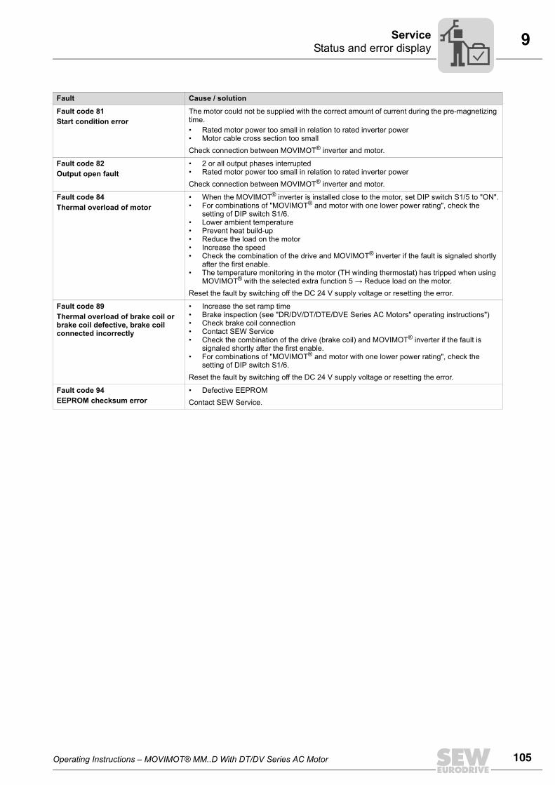
Operating Instructions – MOVIMOT® MM..D With DT/DV Series AC Motor 105
9Status and error displayService
Fault code 81Start condition error
The motor could not be supplied with the correct amount of current during the pre-magnetizing time.• Rated motor power too small in relation to rated inverter power• Motor cable cross section too smallCheck connection between MOVIMOT® inverter and motor.
Fault code 82Output open fault
• 2 or all output phases interrupted• Rated motor power too small in relation to rated inverter powerCheck connection between MOVIMOT® inverter and motor.
Fault code 84 Thermal overload of motor
• When the MOVIMOT® inverter is installed close to the motor, set DIP switch S1/5 to "ON".• For combinations of "MOVIMOT® and motor with one lower power rating", check the
setting of DIP switch S1/6.• Lower ambient temperature• Prevent heat build-up• Reduce the load on the motor • Increase the speed• Check the combination of the drive and MOVIMOT® inverter if the fault is signaled shortly
after the first enable.• The temperature monitoring in the motor (TH winding thermostat) has tripped when using
MOVIMOT® with the selected extra function 5 → Reduce load on the motor.Reset the fault by switching off the DC 24 V supply voltage or resetting the error.
Fault code 89 Thermal overload of brake coil or brake coil defective, brake coil connected incorrectly
• Increase the set ramp time• Brake inspection (see "DR/DV/DT/DTE/DVE Series AC Motors" operating instructions")• Check brake coil connection• Contact SEW Service• Check the combination of the drive (brake coil) and MOVIMOT® inverter if the fault is
signaled shortly after the first enable.• For combinations of "MOVIMOT® and motor with one lower power rating", check the
setting of DIP switch S1/6. Reset the fault by switching off the DC 24 V supply voltage or resetting the error.
Fault code 94EEPROM checksum error
• Defective EEPROMContact SEW Service.
Fault Cause / solution
106 Operating Instructions – MOVIMOT® MM..D With DT/DV Series AC Motor
9 Replacing unitsService
9.2 Replacing units
1. Remove the screws and take off the MOVIMOT® inverter from the terminal box.
2. Compare the data on the nameplate of the previous MOVIMOT® inverter with thedata on the nameplate of the newMOVIMOT® inverter.
3. Set all controls
• DIP switch S1
• DIP switch S2
• Setpoint potentiometer f1
• Switch f2
• Switch t1
on the new MOVIMOT® inverter analogously to the controls of the previousMOVIMOT® inverter.
DANGERWhen working on the unit, dangerous voltage levels may still be present up to one min-ute after the mains is disconnected.
Severe or fatal injuries from electric shock.• Disconnect the MOVIMOT® drive from the supply system and secure it against
unintentional reconnection to the voltage supply.• Then wait at least for 1 minute.
STOPThe previous MOVIMOT® inverter can only be replaced by a MOVIMOT® inverter withthe same power rating and the same input voltage.

Operating Instructions – MOVIMOT® MM..D With DT/DV Series AC Motor 107
9Replacing unitsService
4. Make sure that no Drive-ID module for DR motor types is plugged into theMOVIMOT® inverter
5. Place the new MOVIMOT® inverter onto the terminal box and screw it on.
6. Supply voltage to the MOVIMOT® inverter.
Check whether the new MOVIMOT® inverter is functioning properly.
2037035019
[1] Slot for Drive-ID module
[1]
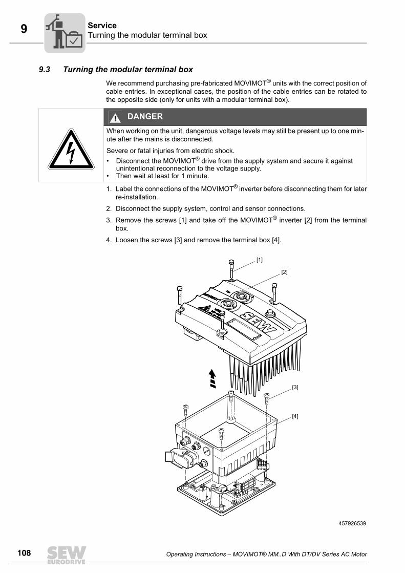
108 Operating Instructions – MOVIMOT® MM..D With DT/DV Series AC Motor
9 Turning the modular terminal boxService
9.3 Turning the modular terminal boxWe recommend purchasing pre-fabricated MOVIMOT® units with the correct position ofcable entries. In exceptional cases, the position of the cable entries can be rotated tothe opposite side (only for units with a modular terminal box).
1. Label the connections of the MOVIMOT® inverter before disconnecting them for laterre-installation.
2. Disconnect the supply system, control and sensor connections.
3. Remove the screws [1] and take off the MOVIMOT® inverter [2] from the terminalbox.
4. Loosen the screws [3] and remove the terminal box [4].
DANGERWhen working on the unit, dangerous voltage levels may still be present up to one min-ute after the mains is disconnected.
Severe or fatal injuries from electric shock.• Disconnect the MOVIMOT® drive from the supply system and secure it against
unintentional reconnection to the voltage supply.• Then wait at least for 1 minute.
457926539
[4]
[3]
[1]
[2]
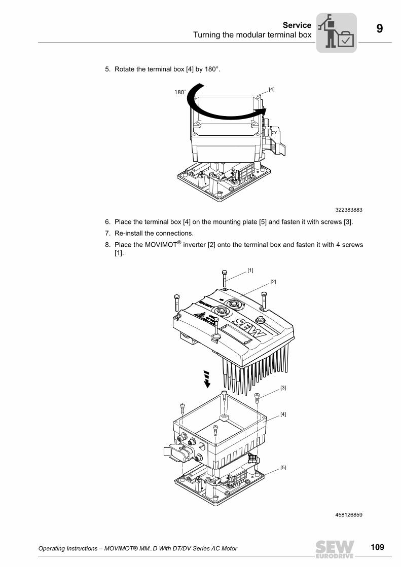
Operating Instructions – MOVIMOT® MM..D With DT/DV Series AC Motor 109
9Turning the modular terminal boxService
5. Rotate the terminal box [4] by 180°.
6. Place the terminal box [4] on the mounting plate [5] and fasten it with screws [3].
7. Re-install the connections.
8. Place the MOVIMOT® inverter [2] onto the terminal box and fasten it with 4 screws[1].
322383883
458126859
180˚ [4]
[4]
[5]
[3]
[1]
[2]
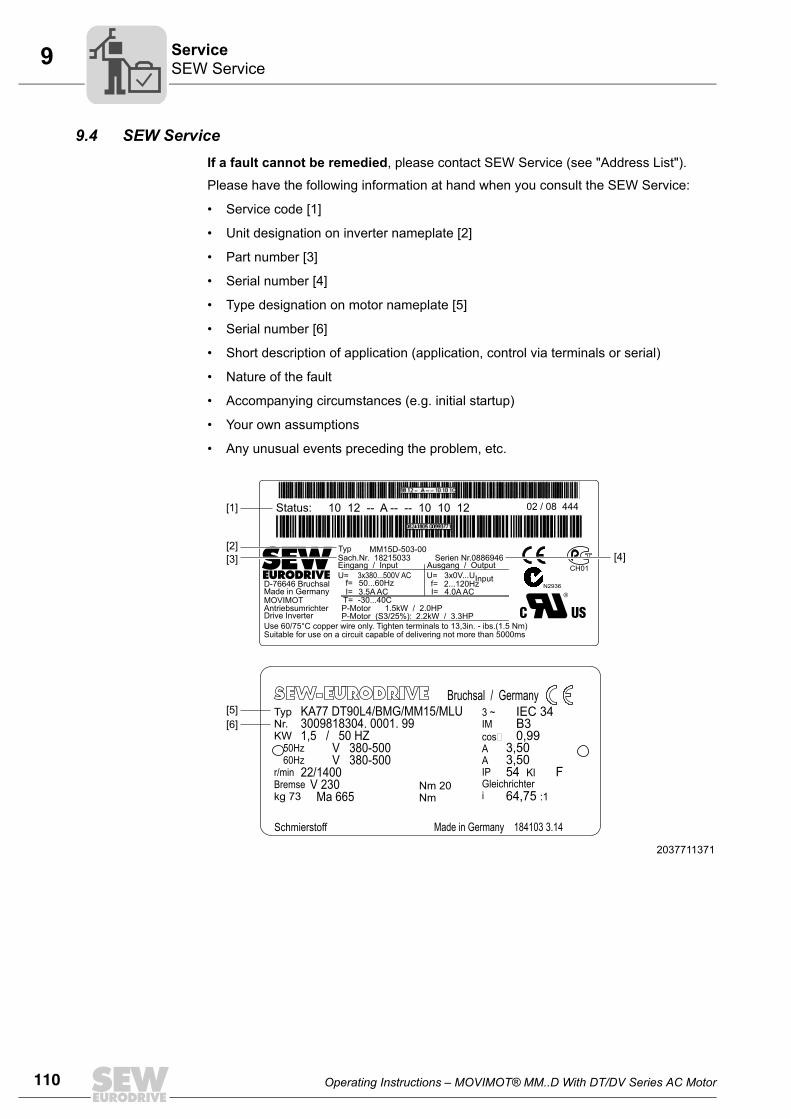
110 Operating Instructions – MOVIMOT® MM..D With DT/DV Series AC Motor
9 SEW ServiceService
9.4 SEW ServiceIf a fault cannot be remedied, please contact SEW Service (see "Address List").
Please have the following information at hand when you consult the SEW Service:
• Service code [1]
• Unit designation on inverter nameplate [2]
• Part number [3]
• Serial number [4]
• Type designation on motor nameplate [5]
• Serial number [6]
• Short description of application (application, control via terminals or serial)
• Nature of the fault
• Accompanying circumstances (e.g. initial startup)
• Your own assumptions
• Any unusual events preceding the problem, etc.
2037711371
[1]
[3] [4][2]
[5][6]
Status: 10 12 -- A -- -- 10 10 12 02 / 08 444
Typ MM15D-503-00Sach.Nr. 18215033Eingang / InputU=
f=I=
T= -30...40CI=3.5A AC 4.0A ACf=50...60HzD-76646 Bruchsal
MOVIMOTAntriebsumrichter P-Motor
P-Motor (S3/25%): 2.2kW / 3.3HP1.5kW / 2.0HP
Drive InverterUse 60/75°C copper wire only. Tighten terminals to 13,3in. - ibs.(1.5 Nm)Suitable for use on a circuit capable of delivering not more than 5000ms
Made in Germany2...120Hz3x0V...UInputU=3x380...500V AC
Ausgang / OutputSerien Nr.0886946
CH01
N2936
TypNr.KW
kg 73
50Hz60Hz
r/minBremse
KA77 DT90L4/BMG/MM15/MLU3009818304. 0001. 991,5 / 50 HZ
V 380-500V 380-500
22/1400V 230
Ma 665
IEC 34B30,99
3,503,5054 F
64,75
Kl
:1
Schmierstoff
Bruchsal / Germany3 ~IMcosAAIPGleichrichteri
Nm 20Nm
Made in Germany 184103 3.14
Operating Instructions – MOVIMOT® MM..D With DT/DV Series AC Motor 111
9Extended storageService
9.5 Extended storageIf the unit is stored for a long time, connect it to the mains voltage for at least 5 minutesevery 2 years. Otherwise, the unit's service life may be reduced.
9.5.1 Procedure when maintenance has been neglectedElectrolytic capacitors are used in the inverters. They are subject to aging effects whendeenergized. This effect can damage the capacitors if the unit is connected using therated voltage after a longer period of storage.
If you have not performed maintenance regularly, SEW-EURODRIVE recommends thatyou increase the line voltage slowly up to the maximum voltage. This can be done, forexample, by using a variable transformer for which the output voltage has been set ac-cording to the following overview. After you have completed the regeneration process,the unit can be used immediately or stored again for an extended period with mainte-nance.
The following stages are recommended:
AC 400/500 V units:
• Stage 1: AC 0 V to AC 350 V within a few seconds
• Stage 2: AC 350 V for 15 minutes
• Stage 3: AC 420 V for 15 minutes
• Stage 4: AC 500 V for 1 hour
9.6 DisposalThis product consists of:
• Iron
• Aluminum
• Copper
• Plastic
• Electronic components
Dispose of all components in accordance with applicable regulations!
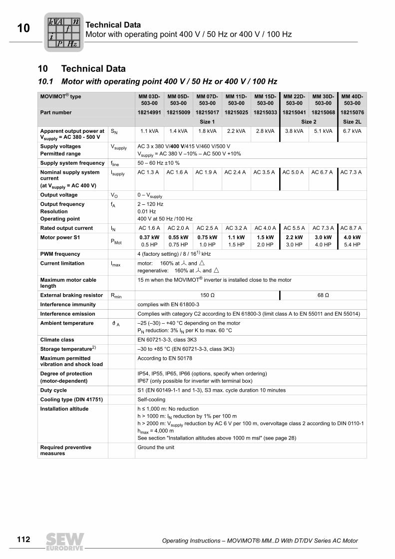
112 Operating Instructions – MOVIMOT® MM..D With DT/DV Series AC Motor
10 Motor with operating point 400 V / 50 Hz or 400 V / 100 HzTechnical Data
10 Technical Data 10.1 Motor with operating point 400 V / 50 Hz or 400 V / 100 Hz
MOVIMOT® type MM 03D- 503-00
MM 05D- 503-00
MM 07D- 503-00
MM 11D- 503-00
MM 15D-503-00
MM 22D-503-00
MM 30D-503-00
MM 40D-503-00
Part number 18214991 18215009 18215017 18215025 18215033 18215041 18215068 18215076
Size 1 Size 2 Size 2L
Apparent output power at Vsupply = AC 380 - 500 V
SN 1.1 kVA 1.4 kVA 1.8 kVA 2.2 kVA 2.8 kVA 3.8 kVA 5.1 kVA 6.7 kVA
Supply voltagesPermitted range
Vsupply AC 3 x 380 V/400 V/415 V/460 V/500 VVsupply = AC 380 V –10% – AC 500 V +10%
Supply system frequency fline 50 – 60 Hz ±10 %
Nominal supply system current (at Vsupply = AC 400 V)
Isupply AC 1.3 A AC 1.6 A AC 1.9 A AC 2.4 A AC 3.5 A AC 5.0 A AC 6.7 A AC 7.3 A
Output voltage VO 0 – Vsupply
Output frequencyResolutionOperating point
fA 2 – 120 Hz0.01 Hz400 V at 50 Hz /100 Hz
Rated output current IN AC 1.6 A AC 2.0 A AC 2.5 A AC 3.2 A AC 4.0 A AC 5.5 A AC 7.3 A AC 8.7 A
Motor power S1PMot
0.37 kW0.5 HP
0.55 kW0.75 HP
0.75 kW1.0 HP
1.1 kW1.5 HP
1.5 kW2.0 HP
2.2 kW3.0 HP
3.0 kW4.0 HP
4.0 kW5.4 HP
PWM frequency 4 (factory setting) / 8 / 161) kHz
Current limitation Imax motor: 160% at and regenerative: 160% at and
Maximum motor cable length
15 m when the MOVIMOT® inverter is installed close to the motor
External braking resistor Rmin 150 Ω 68 Ω
Interference immunity complies with EN 61800-3
Interference emission Complies with category C2 according to EN 61800-3 (limit class A to EN 55011 and EN 55014)
Ambient temperature ϑ A –25 (–30) – +40 °C depending on the motorPN reduction: 3% IN per K to max. 60 °C
Climate class EN 60721-3-3, class 3K3
Storage temperature2) –30 to +85 °C (EN 60721-3-3, class 3K3)
Maximum permitted vibration and shock load
According to EN 50178
Degree of protection (motor-dependent)
IP54, IP55, IP65, IP66 (options, specify when ordering)IP67 (only possible for inverter with terminal box)
Duty cycle S1 (EN 60149-1-1 and 1-3), S3 max. cycle duration 10 minutes
Cooling type (DIN 41751) Self-cooling
Installation altitude h ≤ 1,000 m: No reductionh > 1000 m: IN reduction by 1% per 100 mh > 2000 m: Vsupply reduction by AC 6 V per 100 m, overvoltage class 2 according to DIN 0110-1hmax = 4,000 mSee section "Installation altitudes above 1000 m msl" (see page 28)
Required preventive measures
Ground the unit
Pi
fkVA
Hz
n
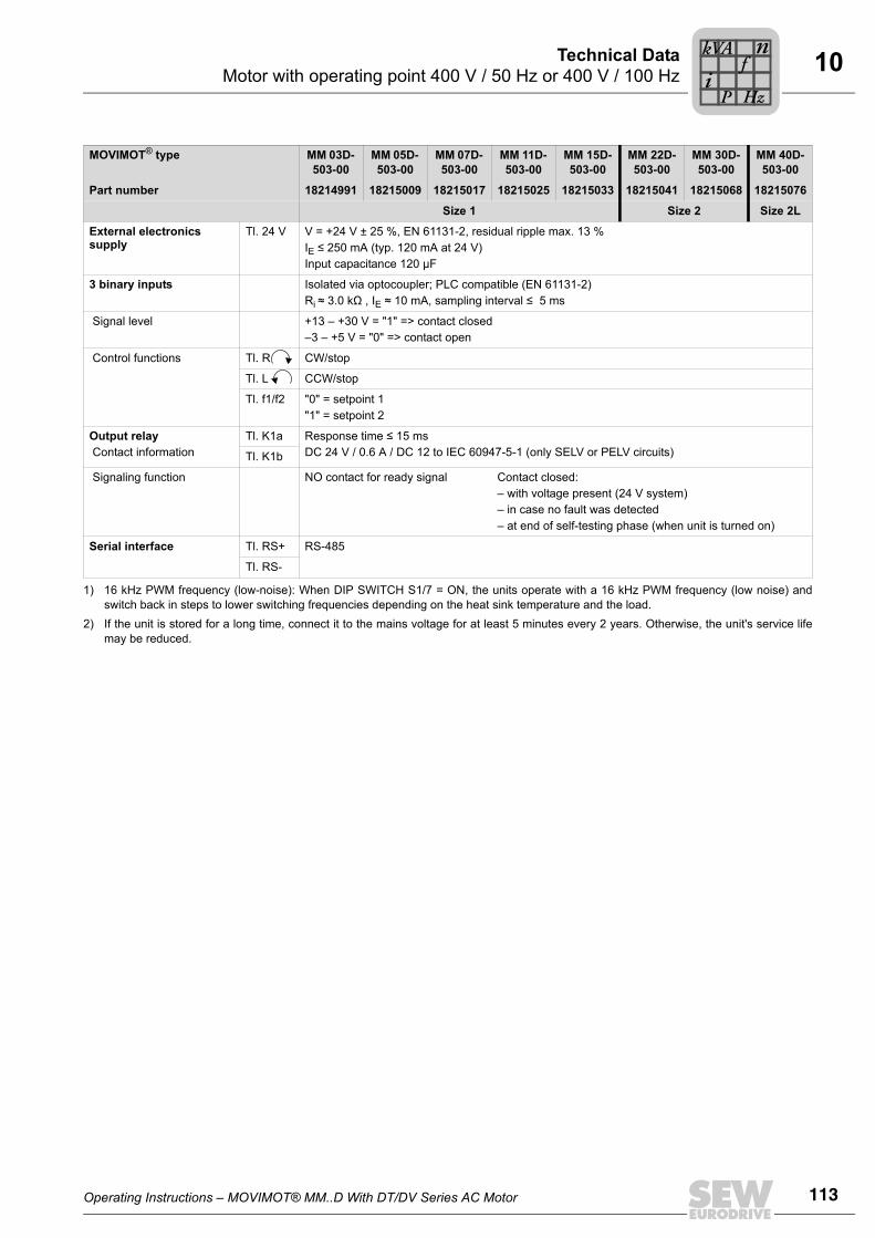
Operating Instructions – MOVIMOT® MM..D With DT/DV Series AC Motor 113
10Motor with operating point 400 V / 50 Hz or 400 V / 100 HzTechnical Data
External electronics supply
Tl. 24 V V = +24 V ± 25 %, EN 61131-2, residual ripple max. 13 %IE ≤ 250 mA (typ. 120 mA at 24 V)Input capacitance 120 µF
3 binary inputs Isolated via optocoupler; PLC compatible (EN 61131-2)Ri ≈ 3.0 kΩ , IE ≈ 10 mA, sampling interval ≤ 5 ms
Signal level +13 – +30 V = "1" => contact closed–3 – +5 V = "0" => contact open
Control functions Tl. R CW/stop
Tl. L CCW/stop
Tl. f1/f2 "0" = setpoint 1 "1" = setpoint 2
Output relay Contact information
Tl. K1a Response time ≤ 15 msDC 24 V / 0.6 A / DC 12 to IEC 60947-5-1 (only SELV or PELV circuits)Tl. K1b
Signaling function NO contact for ready signal Contact closed:– with voltage present (24 V system)– in case no fault was detected– at end of self-testing phase (when unit is turned on)
Serial interface Tl. RS+ RS-485
Tl. RS-
1) 16 kHz PWM frequency (low-noise): When DIP SWITCH S1/7 = ON, the units operate with a 16 kHz PWM frequency (low noise) andswitch back in steps to lower switching frequencies depending on the heat sink temperature and the load.
2) If the unit is stored for a long time, connect it to the mains voltage for at least 5 minutes every 2 years. Otherwise, the unit's service lifemay be reduced.
MOVIMOT® type MM 03D- 503-00
MM 05D- 503-00
MM 07D- 503-00
MM 11D- 503-00
MM 15D-503-00
MM 22D-503-00
MM 30D-503-00
MM 40D-503-00
Part number 18214991 18215009 18215017 18215025 18215033 18215041 18215068 18215076
Size 1 Size 2 Size 2L
Pi
fkVA
Hz
n
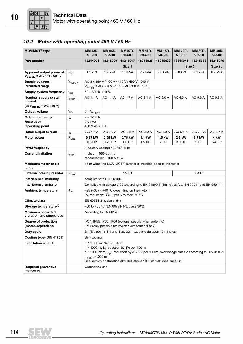
114 Operating Instructions – MOVIMOT® MM..D With DT/DV Series AC Motor
10 Motor with operating point 460 V / 60 HzTechnical Data
10.2 Motor with operating point 460 V / 60 Hz
MOVIMOT® type MM 03D- 503-00
MM 05D- 503-00
MM 07D- 503-00
MM 11D- 503-00
MM 15D-503-00
MM 22D-503-00
MM 30D-503-00
MM 40D-503-00
Part number 18214991 18215009 18215017 18215025 18215033 18215041 18215068 18215076
Size 1 Size 2 Size 2L
Apparent output power at Vsupply = AC 380 - 500 V
SN 1.1 kVA 1.4 kVA 1.8 kVA 2.2 kVA 2.8 kVA 3.8 kVA 5.1 kVA 6.7 kVA
Supply voltagesPermitted range
Vsupply AC 3 x 380 V / 400 V / 415 V / 460 V / 500 VVsupply = AC 380 V –10% – AC 500 V +10%
Supply system frequency fline 50 – 60 Hz ±10 %
Nominal supply system current (at Vsupply = AC 460 V)
Isupply AC 1.1 A AC 1.4 A AC 1.7 A AC 2.1 A AC 3.0 A AC 4.3 A AC 5.8 A AC 6.9 A
Output voltage VO 0 – Vsupply
Output frequencyResolutionOperating point
fA 2 – 120 Hz0.01 Hz460 V at 60 Hz
Rated output current IN AC 1.6 A AC 2.0 A AC 2.5 A AC 3.2 A AC 4.0 A AC 5.5 A AC 7.3 A AC 8.7 A
Motor power PMot 0.37 kW0.5 HP
0.55 kW0.75 HP
0.75 kW1.0 HP
1.1 kW1.5 HP
1.5 kW2 HP
2.2 kW3.0 HP
3.7 kW5 HP
4 kW5.4 HP
PWM frequency 4 (factory setting) / 8 / 161) kHz
Current limitation Imax motor: 160% at regenerative: 160% at
Maximum motor cable length
15 m when the MOVIMOT® inverter is installed close to the motor
External braking resistor Rmin 150 Ω 68 Ω
Interference immunity complies with EN 61800–3
Interference emission Complies with category C2 according to EN 61800-3 (limit class A to EN 55011 and EN 55014)
Ambient temperature ϑ A –25 (–30) – +40 °C depending on the motorPN reduction: 3% IN per K to max. 60 °C
Climate class EN 60721-3-3, class 3K3
Storage temperature2) –30 to +85 °C (EN 60721-3-3, class 3K3)
Maximum permitted vibration and shock load
According to EN 50178
Degree of protection(motor-dependent)
IP54, IP55, IP65, IP66 (options, specify when ordering)IP67 (only possible for inverter with terminal box)
Duty cycle S1 (EN 60149-1-1 and 1-3), S3 max. cycle duration 10 minutes
Cooling type (DIN 41751) Self-cooling
Installation altitude h ≤ 1,000 m: No reductionh > 1000 m: IN reduction by 1% per 100 mh > 2000 m: Vsupply reduction by AC 6 V per 100 m, overvoltage class 2 according to DIN 0110-1hmax = 4,000 mSee section "Installation altitudes above 1000 m msl" (see page 28)
Required preventive measures
Ground the unit
Pi
fkVA
Hz
n
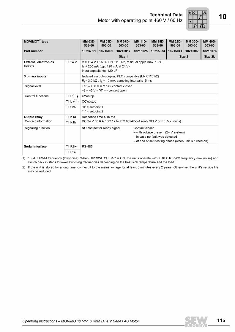
Operating Instructions – MOVIMOT® MM..D With DT/DV Series AC Motor 115
10Motor with operating point 460 V / 60 HzTechnical Data
External electronics supply
Tl. 24 V V = +24 V ± 25 %, EN 61131-2, residual ripple max. 13 %IE ≤ 250 mA (typ. 120 mA at 24 V)Input capacitance 120 µF
3 binary inputs Isolated via optocoupler; PLC compatible (EN 61131-2)Ri ≈ 3.0 kΩ , IE ≈ 10 mA, sampling interval ≤ 5 ms
Signal level +13 – +30 V = "1" => contact closed–3 – +5 V = "0" => contact open
Control functions Tl. R CW/stop
Tl. L CCW/stop
Tl. f1/f2 "0" = setpoint 1 "1" = setpoint 2
Output relay Contact information
Tl. K1a Response time ≤ 15 msDC 24 V / 0.6 A / DC 12 to IEC 60947-5-1 (only SELV or PELV circuits)Tl. K1b
Signaling function NO contact for ready signal Contact closed:– with voltage present (24 V system)– in case no fault was detected– at end of self-testing phase (when unit is turned on)
Serial interface Tl. RS+ RS-485
Tl. RS-
1) 16 kHz PWM frequency (low-noise): When DIP SWITCH S1/7 = ON, the units operate with a 16 kHz PWM frequency (low noise) andswitch back in steps to lower switching frequencies depending on the heat sink temperature and the load.
2) If the unit is stored for a long time, connect it to the mains voltage for at least 5 minutes every 2 years. Otherwise, the unit's service lifemay be reduced.
MOVIMOT® type MM 03D- 503-00
MM 05D- 503-00
MM 07D- 503-00
MM 11D- 503-00
MM 15D-503-00
MM 22D-503-00
MM 30D-503-00
MM 40D-503-00
Part number 18214991 18215009 18215017 18215025 18215033 18215041 18215068 18215076
Size 1 Size 2 Size 2L
Pi
fkVA
Hz
n
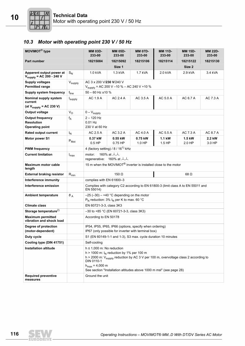
116 Operating Instructions – MOVIMOT® MM..D With DT/DV Series AC Motor
10 Motor with operating point 230 V / 50 HzTechnical Data
10.3 Motor with operating point 230 V / 50 Hz
MOVIMOT® type MM 03D- 233-00
MM 05D- 233-00
MM 07D- 233-00
MM 11D- 233-00
MM 15D- 233-00
MM 22D- 233-00
Part number 18215084 18215092 18215106 18215114 18215122 18215130
Size 1 Size 2
Apparent output power at Vsupply = AC 200 - 240 V
SN 1.0 kVA 1.3 kVA 1.7 kVA 2.0 kVA 2.9 kVA 3.4 kVA
Supply voltagesPermitted range
Vsupply AC 3 x 200 V/230 V/240 VVsupply = AC 200 V –10 % – AC 240 V +10 %
Supply system frequency fline 50 – 60 Hz ±10 %
Nominal supply system current (at Vsupply = AC 230 V)
Isupply AC 1.9 A AC 2.4 A AC 3.5 A AC 5.0 A AC 6.7 A AC 7.3 A
Output voltage VO 0 – Vsupply
Output frequencyResolutionOperating point
fA 2 – 120 Hz0.01 Hz230 V at 60 Hz
Rated output current IN AC 2.5 A AC 3.2 A AC 4.0 A AC 5.5 A AC 7.3 A AC 8.7 A
Motor power S1PMot
0.37 kW0.5 HP
0.55 kW0.75 HP
0.75 kW1.0 HP
1.1 kW1.5 HP
1.5 kW2.0 HP
2.2 kW3.0 HP
PWM frequency 4 (factory setting) / 8 / 161) kHz
Current limitation Imax motor: 160% at regenerative: 160% at
Maximum motor cable length
15 m when the MOVIMOT® inverter is installed close to the motor
External braking resistor Rmin 150 Ω 68 Ω
Interference immunity complies with EN 61800–3
Interference emission Complies with category C2 according to EN 61800-3 (limit class A to EN 55011 and EN 55014)
Ambient temperature ϑ A –25 (–30) – +40 °C depending on the motorPN reduction: 3% IN per K to max. 60 °C
Climate class EN 60721-3-3, class 3K3
Storage temperature2) –30 to +85 °C (EN 60721-3-3, class 3K3)
Maximum permitted vibration and shock load
According to EN 50178
Degree of protection (motor-dependent)
IP54, IP55, IP65, IP66 (options, specify when ordering) IP67 (only possible for inverter with terminal box)
Duty cycle S1 (EN 60149-1-1 and 1-3), S3 max. cycle duration 10 minutes
Cooling type (DIN 41751) Self-cooling
Installation altitude h ≤ 1,000 m: No reductionh > 1000 m: IN reduction by 1% per 100 mh > 2000 m: Vsupply reduction by AC 3 V per 100 m, overvoltage class 2 according to DIN 0110-1hmax = 4,000 mSee section "Installation altitudes above 1000 m msl" (see page 28)
Required preventive measures
Ground the unit
Pi
fkVA
Hz
n
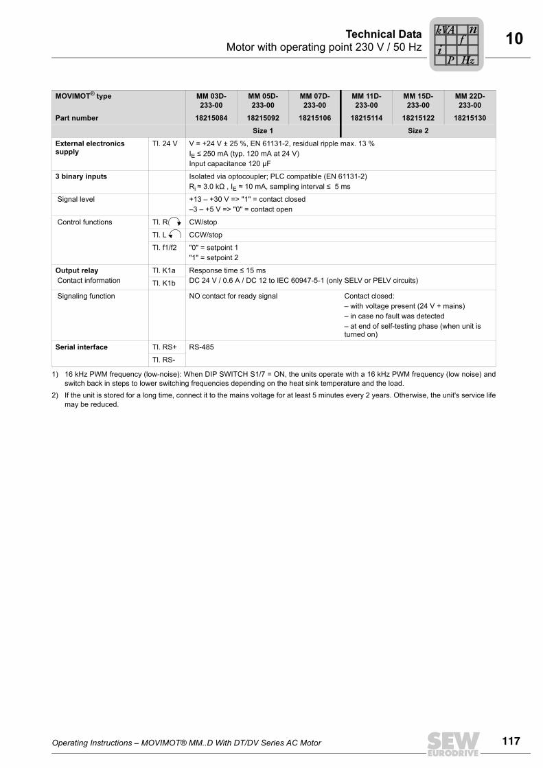
Operating Instructions – MOVIMOT® MM..D With DT/DV Series AC Motor 117
10Motor with operating point 230 V / 50 HzTechnical Data
External electronics supply
Tl. 24 V V = +24 V ± 25 %, EN 61131-2, residual ripple max. 13 %IE ≤ 250 mA (typ. 120 mA at 24 V) Input capacitance 120 µF
3 binary inputs Isolated via optocoupler; PLC compatible (EN 61131-2)Ri ≈ 3.0 kΩ , IE ≈ 10 mA, sampling interval ≤ 5 ms
Signal level +13 – +30 V => "1" = contact closed–3 – +5 V => "0" = contact open
Control functions Tl. R CW/stop
Tl. L CCW/stop
Tl. f1/f2 "0" = setpoint 1 "1" = setpoint 2
Output relay Contact information
Tl. K1a Response time ≤ 15 msDC 24 V / 0.6 A / DC 12 to IEC 60947-5-1 (only SELV or PELV circuits)Tl. K1b
Signaling function NO contact for ready signal Contact closed:– with voltage present (24 V + mains)– in case no fault was detected– at end of self-testing phase (when unit is turned on)
Serial interface Tl. RS+ RS-485
Tl. RS-
1) 16 kHz PWM frequency (low-noise): When DIP SWITCH S1/7 = ON, the units operate with a 16 kHz PWM frequency (low noise) andswitch back in steps to lower switching frequencies depending on the heat sink temperature and the load.
2) If the unit is stored for a long time, connect it to the mains voltage for at least 5 minutes every 2 years. Otherwise, the unit's service lifemay be reduced.
MOVIMOT® type MM 03D- 233-00
MM 05D- 233-00
MM 07D- 233-00
MM 11D- 233-00
MM 15D- 233-00
MM 22D- 233-00
Part number 18215084 18215092 18215106 18215114 18215122 18215130
Size 1 Size 2
Pi
fkVA
Hz
n
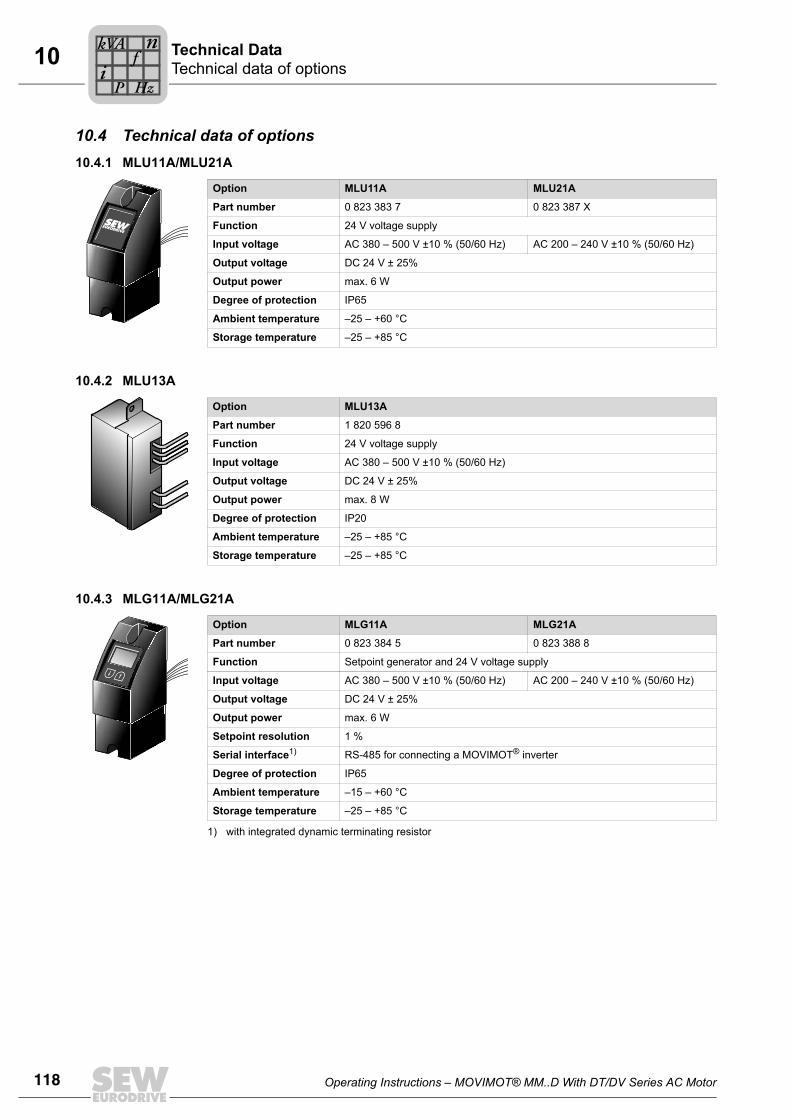
118 Operating Instructions – MOVIMOT® MM..D With DT/DV Series AC Motor
10 Technical data of optionsTechnical Data
10.4 Technical data of options10.4.1 MLU11A/MLU21A
10.4.2 MLU13A
10.4.3 MLG11A/MLG21A
Option MLU11A MLU21A
Part number 0 823 383 7 0 823 387 X
Function 24 V voltage supply
Input voltage AC 380 – 500 V ±10 % (50/60 Hz) AC 200 – 240 V ±10 % (50/60 Hz)
Output voltage DC 24 V ± 25%
Output power max. 6 W
Degree of protection IP65
Ambient temperature –25 – +60 °C
Storage temperature –25 – +85 °C
Option MLU13A
Part number 1 820 596 8
Function 24 V voltage supply
Input voltage AC 380 – 500 V ±10 % (50/60 Hz)
Output voltage DC 24 V ± 25%
Output power max. 8 W
Degree of protection IP20
Ambient temperature –25 – +85 °C
Storage temperature –25 – +85 °C
Option MLG11A MLG21A
Part number 0 823 384 5 0 823 388 8
Function Setpoint generator and 24 V voltage supply
Input voltage AC 380 – 500 V ±10 % (50/60 Hz) AC 200 – 240 V ±10 % (50/60 Hz)
Output voltage DC 24 V ± 25%
Output power max. 6 W
Setpoint resolution 1 %
Serial interface1)
1) with integrated dynamic terminating resistor
RS-485 for connecting a MOVIMOT® inverter
Degree of protection IP65
Ambient temperature –15 – +60 °C
Storage temperature –25 – +85 °C
Pi
fkVA
Hz
n
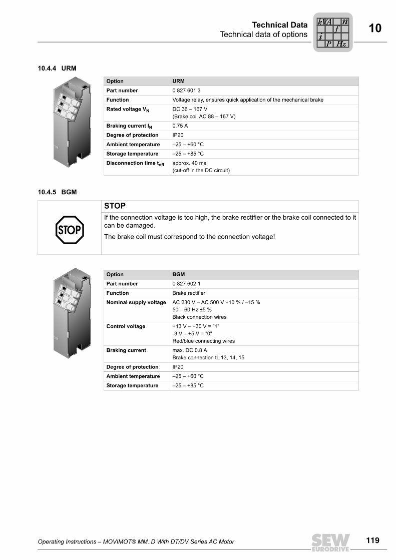
Operating Instructions – MOVIMOT® MM..D With DT/DV Series AC Motor 119
10Technical data of optionsTechnical Data
10.4.4 URM
10.4.5 BGM
Option URM
Part number 0 827 601 3
Function Voltage relay, ensures quick application of the mechanical brake
Rated voltage VN DC 36 – 167 V(Brake coil AC 88 – 167 V)
Braking current IN 0.75 A
Degree of protection IP20
Ambient temperature –25 – +60 °C
Storage temperature –25 – +85 °C
Disconnection time toff approx. 40 ms (cut-off in the DC circuit)
STOPIf the connection voltage is too high, the brake rectifier or the brake coil connected to itcan be damaged.
The brake coil must correspond to the connection voltage!
Option BGM
Part number 0 827 602 1
Function Brake rectifier
Nominal supply voltage AC 230 V – AC 500 V +10 % / –15 %50 – 60 Hz ±5 %Black connection wires
Control voltage +13 V – +30 V = "1" -3 V – +5 V = "0"Red/blue connecting wires
Braking current max. DC 0.8 ABrake connection tl. 13, 14, 15
Degree of protection IP20
Ambient temperature –25 – +60 °C
Storage temperature –25 – +85 °C
Pi
fkVA
Hz
n
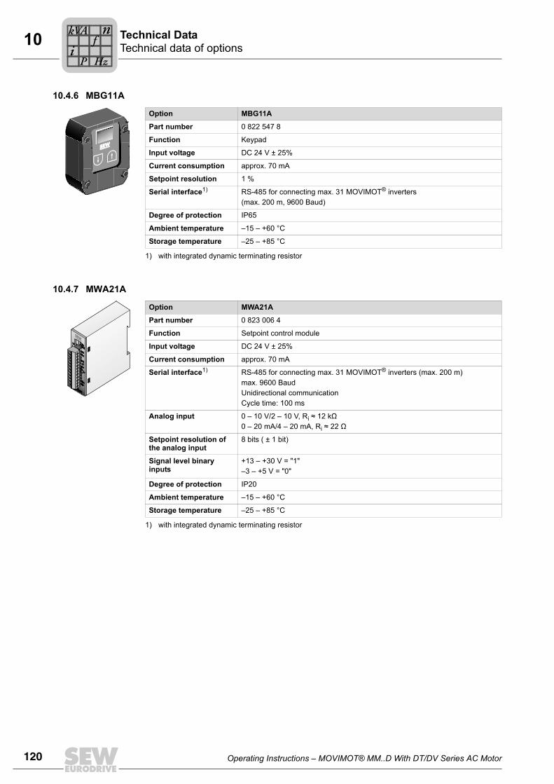
120 Operating Instructions – MOVIMOT® MM..D With DT/DV Series AC Motor
10 Technical data of optionsTechnical Data
10.4.6 MBG11A
10.4.7 MWA21A
Option MBG11A
Part number 0 822 547 8
Function Keypad
Input voltage DC 24 V ± 25%
Current consumption approx. 70 mA
Setpoint resolution 1 %
Serial interface1)
1) with integrated dynamic terminating resistor
RS-485 for connecting max. 31 MOVIMOT® inverters (max. 200 m, 9600 Baud)
Degree of protection IP65
Ambient temperature –15 – +60 °C
Storage temperature –25 – +85 °C
Option MWA21A
Part number 0 823 006 4
Function Setpoint control module
Input voltage DC 24 V ± 25%
Current consumption approx. 70 mA
Serial interface1)
1) with integrated dynamic terminating resistor
RS-485 for connecting max. 31 MOVIMOT® inverters (max. 200 m)max. 9600 BaudUnidirectional communicationCycle time: 100 ms
Analog input 0 – 10 V/2 – 10 V, Ri ≈ 12 kΩ 0 – 20 mA/4 – 20 mA, Ri ≈ 22 Ω
Setpoint resolution of the analog input
8 bits ( ± 1 bit)
Signal level binary inputs
+13 – +30 V = "1"–3 – +5 V = "0"
Degree of protection IP20
Ambient temperature –15 – +60 °C
Storage temperature –25 – +85 °C
Pi
fkVA
Hz
n
Operating Instructions – MOVIMOT® MM..D With DT/DV Series AC Motor 121
10Integrated RS-485 interfaceTechnical Data
10.5 Integrated RS-485 interface
10.6 Diagnostics interface
RS-485 interface
Standard RS-485 to EIA standard (with integrated dynamic terminating resistor)
Baud rate 9.6 kBd31.25 kBaud (in connection with MF.., MQ.., MOVIFIT® MC fieldbus interfaces)
Start bits 1 start bit
Stop bits 1 stop bit
Data bits 8 data bits
Parity 1 parity bit, completing for even parity (even parity)
Data direction Bi-directional
Duty cycle Asynchronous, semi-duplex
Timeout interval 1 s
Cable length max. 200 m in RS-485 operation with 9,600 Baudmax. 30 m at transmission rate: 31250 baud 1)
1) Transmission rate of 31,250 Baud will be detected automatically in case of operation with MF.. fieldbusinterface.
Number of stations
• Max. 32 stations (1 bus master2) + 31 MOVIMOT®) broadcast and group addresses possible
• 15 MOVIMOT® can be addressed individually
2) ext. control or options MBG11A, MWA21A or MLG..A
Diagnostic interface X50
Standard RS-485 to EIA standard (with integrated dynamic terminating resistor)
Baud rate 9.6 kBd
Start bits 1 start bit
Stop bits 1 stop bit
Data bits 8 data bits
Parity 1 parity bit, completing for even parity (even parity)
Data direction Bi-directional
Duty cycle asynchronous, semi-duplex
Connection RJ10 socket (point-to-point connection, without process data)
Pi
fkVA
Hz
n
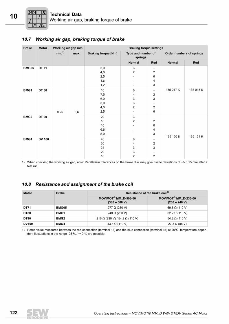
122 Operating Instructions – MOVIMOT® MM..D With DT/DV Series AC Motor
10 Working air gap, braking torque of brakeTechnical Data
10.7 Working air gap, braking torque of brake
10.8 Resistance and assignment of the brake coil
Brake Motor Working air gap mm Braking torque settings
min.1)
1) When checking the working air gap, note: Parallelism tolerances on the brake disk may give rise to deviations of +/- 0.15 mm after atest run.
max. Braking torque [Nm] Type and number of springs
Order numbers of springs
Normal Red Normal Red
BMG05 DT 71
0,25 0,6
5,04,02,51,61,2
32---
-2643
135 017 X 135 018 8BMG1 DT 80 107,56,05,04,02,5
64332-
-23-26
BMG2 DT 90 2016106,65,0
32---
-2643
135 150 8 135 151 6BMG4 DV 100 40
30242016
64332
-23-2
Motor Brake Resistance of the brake coil1)
1) Rated value measured between the red connection (terminal 13) and the blue connection (terminal 15) at 20°C, temperature-depen-dent fluctuations in the range -25 % / +40 % are possible.
MOVIMOT® MM..D-503-00(380 – 500 V)
MOVIMOT® MM..D-233-00(200 – 240 V)
DT71 BMG05 277 Ω (230 V) 69.6 Ω (110 V)
DT80 BMG1 248 Ω (230 V) 62.2 Ω (110 V)
DT90 BMG2 216 Ω (230 V) / 54.2 Ω (110 V) 54.2 Ω (110 V)
DV100 BMG4 43.5 Ω (110 V) 27.3 Ω (88 V)
Pi
fkVA
Hz
n
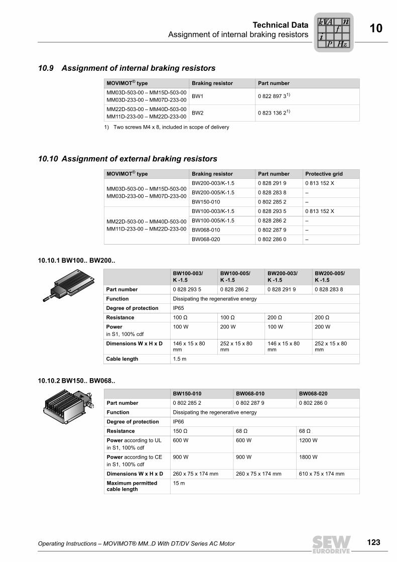
Operating Instructions – MOVIMOT® MM..D With DT/DV Series AC Motor 123
10Assignment of internal braking resistorsTechnical Data
10.9 Assignment of internal braking resistors
10.10 Assignment of external braking resistors
10.10.1 BW100.. BW200..
10.10.2 BW150.. BW068..
MOVIMOT® type Braking resistor Part number
MM03D-503-00 – MM15D-503-00MM03D-233-00 – MM07D-233-00
BW1 0 822 897 31)
1) Two screws M4 x 8, included in scope of delivery
MM22D-503-00 – MM40D-503-00MM11D-233-00 – MM22D-233-00
BW2 0 823 136 21)
MOVIMOT® type Braking resistor Part number Protective grid
MM03D-503-00 – MM15D-503-00MM03D-233-00 – MM07D-233-00
BW200-003/K-1.5 0 828 291 9 0 813 152 X
BW200-005/K-1.5 0 828 283 8 –
BW150-010 0 802 285 2 –
MM22D-503-00 – MM40D-503-00MM11D-233-00 – MM22D-233-00
BW100-003/K-1.5 0 828 293 5 0 813 152 X
BW100-005/K-1.5 0 828 286 2 –
BW068-010 0 802 287 9 –
BW068-020 0 802 286 0 –
BW100-003/K -1.5
BW100-005/K -1.5
BW200-003/K -1.5
BW200-005/K -1.5
Part number 0 828 293 5 0 828 286 2 0 828 291 9 0 828 283 8
Function Dissipating the regenerative energy
Degree of protection IP65
Resistance 100 Ω 100 Ω 200 Ω 200 Ω
Powerin S1, 100% cdf
100 W 200 W 100 W 200 W
Dimensions W x H x D 146 x 15 x 80 mm
252 x 15 x 80 mm
146 x 15 x 80 mm
252 x 15 x 80 mm
Cable length 1.5 m
BW150-010 BW068-010 BW068-020
Part number 0 802 285 2 0 802 287 9 0 802 286 0
Function Dissipating the regenerative energy
Degree of protection IP66
Resistance 150 Ω 68 Ω 68 Ω
Power according to ULin S1, 100% cdf
600 W 600 W 1200 W
Power according to CEin S1, 100% cdf
900 W 900 W 1800 W
Dimensions W x H x D 260 x 75 x 174 mm 260 x 75 x 174 mm 610 x 75 x 174 mm
Maximum permitted cable length
15 m
Pi
fkVA
Hz
n
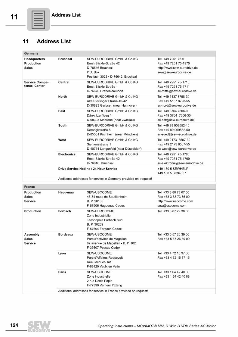
124 Operating Instructions – MOVIMOT® MM..D With DT/DV Series AC Motor
11 Address List
11 Address List
Germany
HeadquartersProductionSales
Bruchsal SEW-EURODRIVE GmbH & Co KGErnst-Blickle-Straße 42 D-76646 BruchsalP.O. BoxPostfach 3023 • D-76642 Bruchsal
Tel. +49 7251 75-0Fax +49 7251 75-1970http://[email protected]
Service Compe-tence Center
Central SEW-EURODRIVE GmbH & Co KGErnst-Blickle-Straße 1 D-76676 Graben-Neudorf
Tel. +49 7251 75-1710Fax +49 7251 [email protected]
North SEW-EURODRIVE GmbH & Co KGAlte Ricklinger Straße 40-42 D-30823 Garbsen (near Hannover)
Tel. +49 5137 8798-30Fax +49 5137 [email protected]
East SEW-EURODRIVE GmbH & Co KGDänkritzer Weg 1D-08393 Meerane (near Zwickau)
Tel. +49 3764 7606-0Fax +49 3764 [email protected]
South SEW-EURODRIVE GmbH & Co KGDomagkstraße 5D-85551 Kirchheim (near München)
Tel. +49 89 909552-10Fax +49 89 [email protected]
West SEW-EURODRIVE GmbH & Co KGSiemensstraße 1D-40764 Langenfeld (near Düsseldorf)
Tel. +49 2173 8507-30Fax +49 2173 [email protected]
Electronics SEW-EURODRIVE GmbH & Co KGErnst-Blickle-Straße 42 D-76646 Bruchsal
Tel. +49 7251 75-1780Fax +49 7251 [email protected]
Drive Service Hotline / 24 Hour Service +49 180 5 SEWHELP+49 180 5 7394357
Additional addresses for service in Germany provided on request!
France
ProductionSalesService
Haguenau SEW-USOCOME 48-54 route de Soufflenheim B. P. 20185F-67506 Haguenau Cedex
Tel. +33 3 88 73 67 00 Fax +33 3 88 73 66 00http://[email protected]
Production Forbach SEW-EUROCOME Zone Industrielle Technopôle Forbach SudB. P. 30269F-57604 Forbach Cedex
Tel. +33 3 87 29 38 00
AssemblySalesService
Bordeaux SEW-USOCOME Parc d'activités de Magellan62 avenue de Magellan - B. P. 182F-33607 Pessac Cedex
Tel. +33 5 57 26 39 00Fax +33 5 57 26 39 09
Lyon SEW-USOCOME Parc d'Affaires RooseveltRue Jacques TatiF-69120 Vaulx en Velin
Tel. +33 4 72 15 37 00Fax +33 4 72 15 37 15
Paris SEW-USOCOME Zone industrielle 2 rue Denis Papin F-77390 Verneuil I'Etang
Tel. +33 1 64 42 40 80Fax +33 1 64 42 40 88
Additional addresses for service in France provided on request!
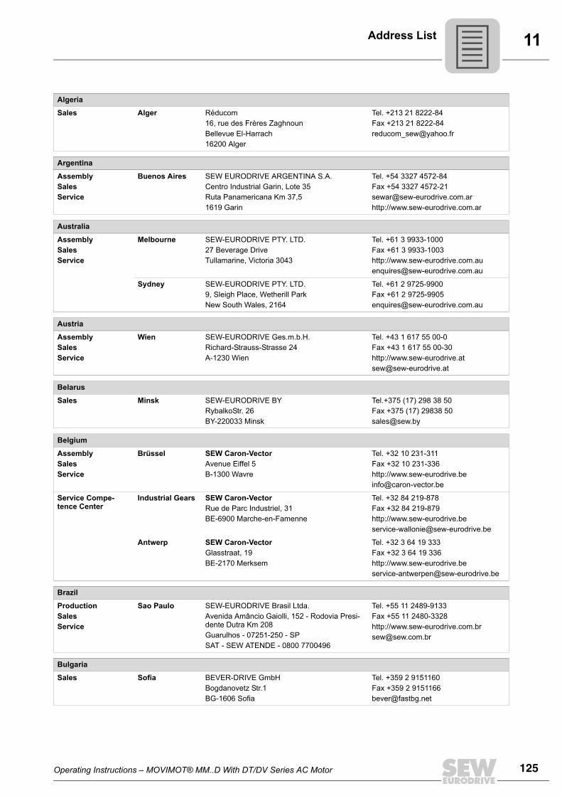
Operating Instructions – MOVIMOT® MM..D With DT/DV Series AC Motor 125
11Address List
Algeria
Sales Alger Réducom 16, rue des Frères ZaghnounBellevue El-Harrach16200 Alger
Tel. +213 21 8222-84Fax +213 21 [email protected]
Argentina
AssemblySalesService
Buenos Aires SEW EURODRIVE ARGENTINA S.A.Centro Industrial Garin, Lote 35Ruta Panamericana Km 37,51619 Garin
Tel. +54 3327 4572-84Fax +54 3327 [email protected]://www.sew-eurodrive.com.ar
Australia
AssemblySalesService
Melbourne SEW-EURODRIVE PTY. LTD.27 Beverage DriveTullamarine, Victoria 3043
Tel. +61 3 9933-1000Fax +61 3 9933-1003http://[email protected]
Sydney SEW-EURODRIVE PTY. LTD.9, Sleigh Place, Wetherill Park New South Wales, 2164
Tel. +61 2 9725-9900Fax +61 2 [email protected]
Austria
AssemblySalesService
Wien SEW-EURODRIVE Ges.m.b.H. Richard-Strauss-Strasse 24A-1230 Wien
Tel. +43 1 617 55 00-0Fax +43 1 617 55 00-30http://[email protected]
Belarus
Sales Minsk SEW-EURODRIVE BYRybalkoStr. 26BY-220033 Minsk
Tel.+375 (17) 298 38 50Fax +375 (17) 29838 [email protected]
Belgium
AssemblySalesService
Brüssel SEW Caron-VectorAvenue Eiffel 5B-1300 Wavre
Tel. +32 10 231-311Fax +32 10 231-336http://[email protected]
Service Compe-tence Center
Industrial Gears SEW Caron-VectorRue de Parc Industriel, 31BE-6900 Marche-en-Famenne
Tel. +32 84 219-878Fax +32 84 219-879http://[email protected]
Antwerp SEW Caron-VectorGlasstraat, 19BE-2170 Merksem
Tel. +32 3 64 19 333Fax +32 3 64 19 336http://[email protected]
Brazil
ProductionSalesService
Sao Paulo SEW-EURODRIVE Brasil Ltda.Avenida Amâncio Gaiolli, 152 - Rodovia Presi-dente Dutra Km 208Guarulhos - 07251-250 - SPSAT - SEW ATENDE - 0800 7700496
Tel. +55 11 2489-9133Fax +55 11 2480-3328http://[email protected]
Bulgaria
Sales Sofia BEVER-DRIVE GmbHBogdanovetz Str.1BG-1606 Sofia
Tel. +359 2 9151160Fax +359 2 [email protected]
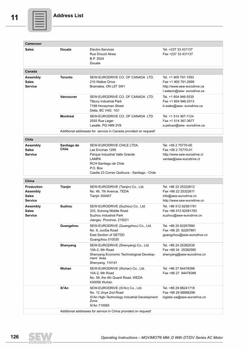
126 Operating Instructions – MOVIMOT® MM..D With DT/DV Series AC Motor
11 Address List
Cameroon
Sales Douala Electro-ServicesRue Drouot AkwaB.P. 2024Douala
Tel. +237 33 431137Fax +237 33 431137
Canada
AssemblySalesService
Toronto SEW-EURODRIVE CO. OF CANADA LTD. 210 Walker Drive Bramalea, ON L6T 3W1
Tel. +1 905 791-1553Fax +1 905 791-2999http://www.sew-eurodrive.cal.watson@sew- eurodrive.ca
Vancouver SEW-EURODRIVE CO. OF CANADA LTD.Tilbury Industrial Park7188 Honeyman Street Delta, BC V4G 1G1
Tel. +1 604 946-5535Fax +1 604 946-2513b.wake@sew- eurodrive.ca
Montreal SEW-EURODRIVE CO. OF CANADA LTD.2555 Rue Leger Lasalle, PQ H8N 2V9
Tel. +1 514 367-1124Fax +1 514 367-3677a.peluso@sew- eurodrive.ca
Additional addresses for service in Canada provided on request!
Chile
AssemblySalesService
Santiago de Chile
SEW-EURODRIVE CHILE LTDA.Las Encinas 1295Parque Industrial Valle GrandeLAMPARCH-Santiago de ChileP.O. BoxCasilla 23 Correo Quilicura - Santiago - Chile
Tel. +56 2 75770-00Fax +56 2 75770-01http://[email protected]
China
ProductionAssemblySalesService
Tianjin SEW-EURODRIVE (Tianjin) Co., Ltd.No. 46, 7th Avenue, TEDATianjin 300457
Tel. +86 22 25322612Fax +86 22 [email protected]://www.sew-eurodrive.cn
AssemblySalesService
Suzhou SEW-EURODRIVE (Suzhou) Co., Ltd.333, Suhong Middle RoadSuzhou Industrial ParkJiangsu Province, 215021
Tel. +86 512 62581781Fax +86 512 [email protected]
Guangzhou SEW-EURODRIVE (Guangzhou) Co., Ltd.No. 9, JunDa RoadEast Section of GETDDGuangzhou 510530
Tel. +86 20 82267890Fax +86 20 [email protected]
Shenyang SEW-EURODRIVE (Shenyang) Co., Ltd.10A-2, 6th RoadShenyang Economic Technological Develop-ment AreaShenyang, 110141
Tel. +86 24 25382538Fax +86 24 [email protected]
Wuhan SEW-EURODRIVE (Wuhan) Co., Ltd.10A-2, 6th RoadNo. 59, the 4th Quanli Road, WEDA430056 Wuhan
Tel. +86 27 84478398Fax +86 27 84478388
Xi'An SEW-EURODRIVE (Xi'An) Co., Ltd.No. 12 Jinye 2nd RoadXi'An High-Technology Industrial Development ZoneXi'An 710065
Tel. +86 29 88241718Fax +86 29 [email protected]
Additional addresses for service in China provided on request!
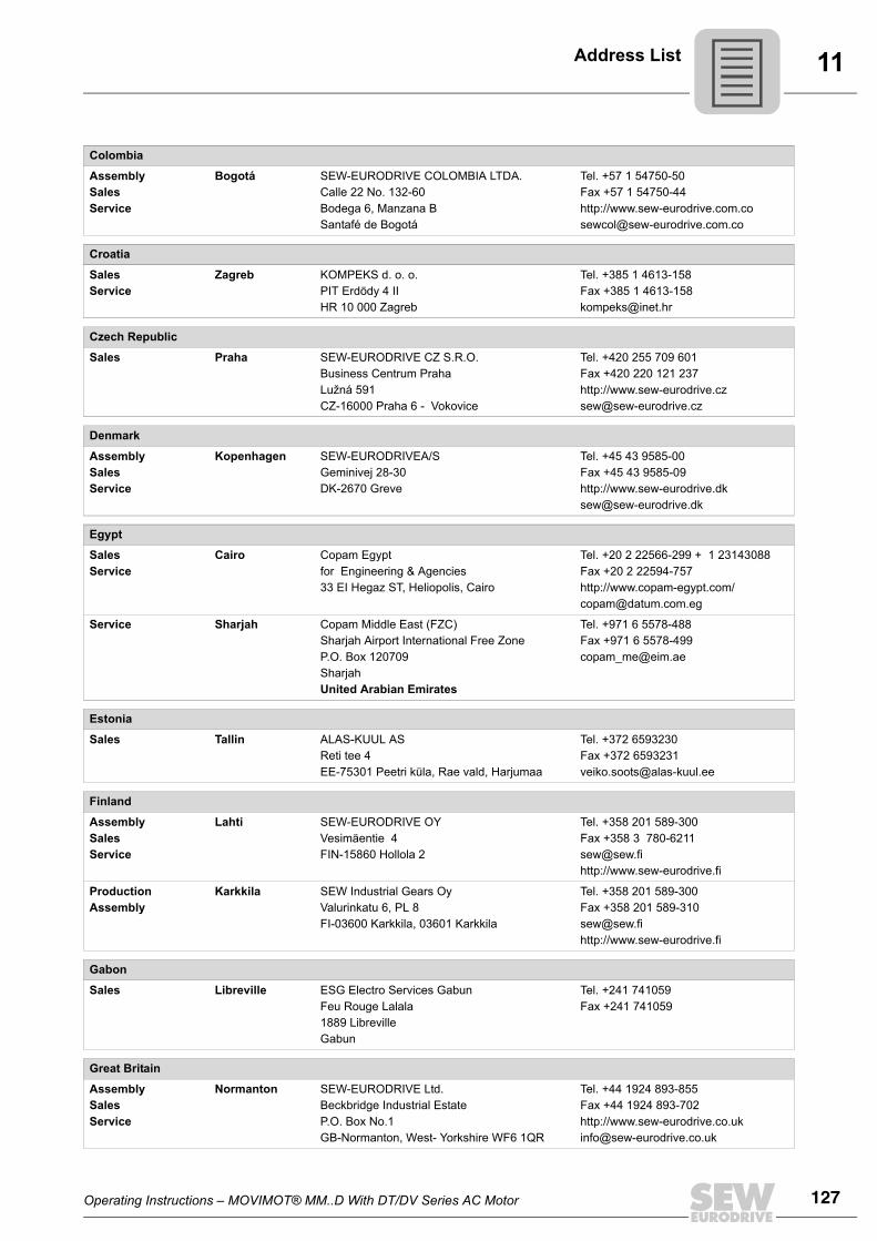
Operating Instructions – MOVIMOT® MM..D With DT/DV Series AC Motor 127
11Address List
Colombia
AssemblySalesService
Bogotá SEW-EURODRIVE COLOMBIA LTDA. Calle 22 No. 132-60Bodega 6, Manzana BSantafé de Bogotá
Tel. +57 1 54750-50Fax +57 1 54750-44http://[email protected]
Croatia
SalesService
Zagreb KOMPEKS d. o. o.PIT Erdödy 4 IIHR 10 000 Zagreb
Tel. +385 1 4613-158Fax +385 1 [email protected]
Czech Republic
Sales Praha SEW-EURODRIVE CZ S.R.O.Business Centrum Praha Lužná 591CZ-16000 Praha 6 - Vokovice
Tel. +420 255 709 601Fax +420 220 121 237http://[email protected]
Denmark
AssemblySalesService
Kopenhagen SEW-EURODRIVEA/SGeminivej 28-30DK-2670 Greve
Tel. +45 43 9585-00Fax +45 43 9585-09http://[email protected]
Egypt
SalesService
Cairo Copam Egypt for Engineering & Agencies33 EI Hegaz ST, Heliopolis, Cairo
Tel. +20 2 22566-299 + 1 23143088Fax +20 2 22594-757http://www.copam-egypt.com/ [email protected]
Service Sharjah Copam Middle East (FZC) Sharjah Airport International Free ZoneP.O. Box 120709SharjahUnited Arabian Emirates
Tel. +971 6 5578-488Fax +971 6 [email protected]
Estonia
Sales Tallin ALAS-KUUL ASReti tee 4EE-75301 Peetri küla, Rae vald, Harjumaa
Tel. +372 6593230Fax +372 [email protected]
Finland
AssemblySalesService
Lahti SEW-EURODRIVE OYVesimäentie 4FIN-15860 Hollola 2
Tel. +358 201 589-300Fax +358 3 [email protected]://www.sew-eurodrive.fi
ProductionAssembly
Karkkila SEW Industrial Gears OyValurinkatu 6, PL 8FI-03600 Karkkila, 03601 Karkkila
Tel. +358 201 589-300Fax +358 201 [email protected]://www.sew-eurodrive.fi
Gabon
Sales Libreville ESG Electro Services GabunFeu Rouge Lalala1889 LibrevilleGabun
Tel. +241 741059Fax +241 741059
Great Britain
AssemblySalesService
Normanton SEW-EURODRIVE Ltd.Beckbridge Industrial Estate P.O. Box No.1GB-Normanton, West- Yorkshire WF6 1QR
Tel. +44 1924 893-855Fax +44 1924 893-702http://[email protected]
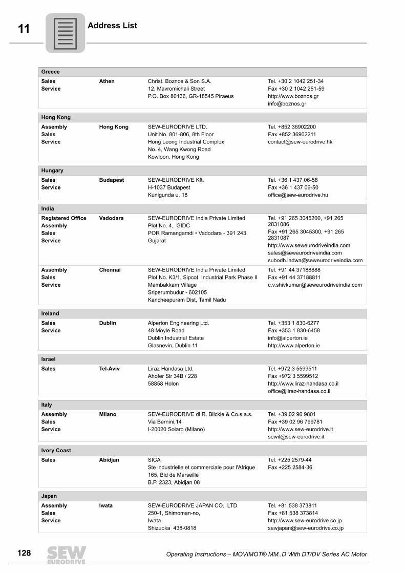
128 Operating Instructions – MOVIMOT® MM..D With DT/DV Series AC Motor
11 Address List
Greece
SalesService
Athen Christ. Boznos & Son S.A.12, Mavromichali StreetP.O. Box 80136, GR-18545 Piraeus
Tel. +30 2 1042 251-34 Fax +30 2 1042 251-59http://[email protected]
Hong Kong
AssemblySalesService
Hong Kong SEW-EURODRIVE LTD.Unit No. 801-806, 8th FloorHong Leong Industrial ComplexNo. 4, Wang Kwong Road Kowloon, Hong Kong
Tel. +852 36902200Fax +852 [email protected]
Hungary
SalesService
Budapest SEW-EURODRIVE Kft.H-1037 BudapestKunigunda u. 18
Tel. +36 1 437 06-58Fax +36 1 437 [email protected]
India
Registered OfficeAssemblySalesService
Vadodara SEW-EURODRIVE India Private LimitedPlot No. 4, GIDCPOR Ramangamdi • Vadodara - 391 243Gujarat
Tel. +91 265 3045200, +91 265 2831086Fax +91 265 3045300, +91 265 2831087http://[email protected]@seweurodriveindia.com
AssemblySalesService
Chennai SEW-EURODRIVE India Private LimitedPlot No. K3/1, Sipcot Industrial Park Phase IIMambakkam VillageSriperumbudur - 602105Kancheepuram Dist, Tamil Nadu
Tel. +91 44 37188888Fax +91 44 [email protected]
Ireland
SalesService
Dublin Alperton Engineering Ltd. 48 Moyle RoadDublin Industrial EstateGlasnevin, Dublin 11
Tel. +353 1 830-6277Fax +353 1 [email protected]://www.alperton.ie
Israel
Sales Tel-Aviv Liraz Handasa Ltd. Ahofer Str 34B / 22858858 Holon
Tel. +972 3 5599511Fax +972 3 5599512http://[email protected]
Italy
AssemblySalesService
Milano SEW-EURODRIVE di R. Blickle & Co.s.a.s.Via Bernini,14 I-20020 Solaro (Milano)
Tel. +39 02 96 9801Fax +39 02 96 799781http://[email protected]
Ivory Coast
Sales Abidjan SICASte industrielle et commerciale pour l'Afrique165, Bld de MarseilleB.P. 2323, Abidjan 08
Tel. +225 2579-44Fax +225 2584-36
Japan
AssemblySalesService
Iwata SEW-EURODRIVE JAPAN CO., LTD 250-1, Shimoman-no,IwataShizuoka 438-0818
Tel. +81 538 373811Fax +81 538 373814http://[email protected]
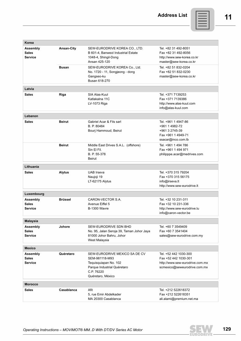
Operating Instructions – MOVIMOT® MM..D With DT/DV Series AC Motor 129
11Address List
Korea
AssemblySalesService
Ansan-City SEW-EURODRIVE KOREA CO., LTD. B 601-4, Banweol Industrial Estate 1048-4, Shingil-DongAnsan 425-120
Tel. +82 31 492-8051Fax +82 31 492-8056http://[email protected]
Busan SEW-EURODRIVE KOREA Co., Ltd.No. 1720 - 11, Songjeong - dongGangseo-kuBusan 618-270
Tel. +82 51 832-0204Fax +82 51 [email protected]
Latvia
Sales Riga SIA Alas-KuulKatlakalna 11CLV-1073 Riga
Tel. +371 7139253Fax +371 7139386http://[email protected]
Lebanon
Sales Beirut Gabriel Acar & Fils sarlB. P. 80484Bourj Hammoud, Beirut
Tel. +961 1 4947-86 +961 1 4982-72+961 3 2745-39Fax +961 1 4949-71 [email protected]
Beirut Middle East Drives S.A.L. (offshore)Sin El Fil.B. P. 55-378Beirut
Tel. +961 1 494 786Fax +961 1 494 [email protected]
Lithuania
Sales Alytus UAB IrsevaNaujoji 19LT-62175 Alytus
Tel. +370 315 79204Fax +370 315 [email protected]://www.sew-eurodrive.lt
Luxembourg
AssemblySalesService
Brüssel CARON-VECTOR S.A.Avenue Eiffel 5B-1300 Wavre
Tel. +32 10 231-311Fax +32 10 231-336http://[email protected]
Malaysia
AssemblySalesService
Johore SEW-EURODRIVE SDN BHD No. 95, Jalan Seroja 39, Taman Johor Jaya81000 Johor Bahru, JohorWest Malaysia
Tel. +60 7 3549409Fax +60 7 [email protected]
Mexico
AssemblySalesService
Quéretaro SEW-EURODRIVE MEXICO SA DE CVSEM-981118-M93Tequisquiapan No. 102Parque Industrial QuéretaroC.P. 76220Quéretaro, México
Tel. +52 442 1030-300Fax +52 442 1030-301http://[email protected]
Morocco
Sales Casablanca Afit5, rue Emir AbdelkaderMA 20300 Casablanca
Tel. +212 522618372Fax +212 [email protected]
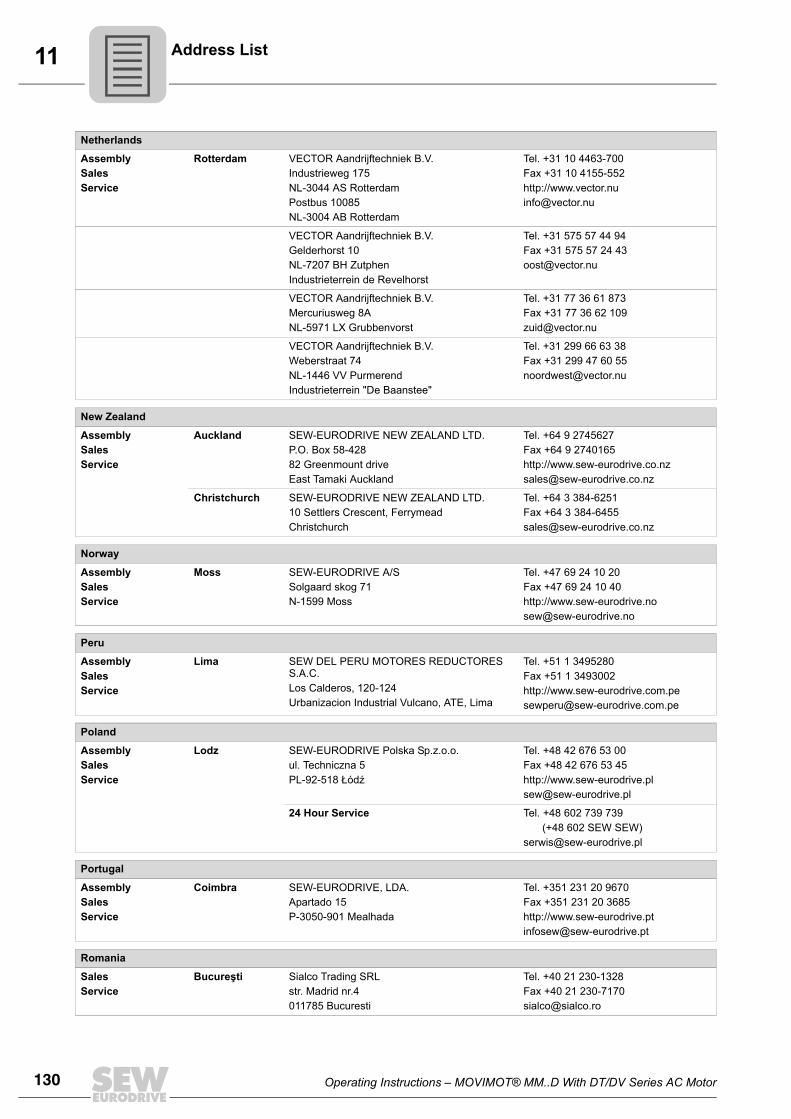
130 Operating Instructions – MOVIMOT® MM..D With DT/DV Series AC Motor
11 Address List
Netherlands
AssemblySalesService
Rotterdam VECTOR Aandrijftechniek B.V. Industrieweg 175 NL-3044 AS RotterdamPostbus 10085NL-3004 AB Rotterdam
Tel. +31 10 4463-700Fax +31 10 4155-552http://[email protected]
VECTOR Aandrijftechniek B.V. Gelderhorst 10NL-7207 BH ZutphenIndustrieterrein de Revelhorst
Tel. +31 575 57 44 94Fax +31 575 57 24 [email protected]
VECTOR Aandrijftechniek B.V. Mercuriusweg 8ANL-5971 LX Grubbenvorst
Tel. +31 77 36 61 873Fax +31 77 36 62 [email protected]
VECTOR Aandrijftechniek B.V. Weberstraat 74NL-1446 VV PurmerendIndustrieterrein "De Baanstee"
Tel. +31 299 66 63 38Fax +31 299 47 60 [email protected]
New Zealand
AssemblySalesService
Auckland SEW-EURODRIVE NEW ZEALAND LTD. P.O. Box 58-428 82 Greenmount driveEast Tamaki Auckland
Tel. +64 9 2745627Fax +64 9 2740165http://[email protected]
Christchurch SEW-EURODRIVE NEW ZEALAND LTD. 10 Settlers Crescent, FerrymeadChristchurch
Tel. +64 3 384-6251Fax +64 3 [email protected]
Norway
AssemblySalesService
Moss SEW-EURODRIVE A/SSolgaard skog 71N-1599 Moss
Tel. +47 69 24 10 20Fax +47 69 24 10 40http://[email protected]
Peru
AssemblySalesService
Lima SEW DEL PERU MOTORES REDUCTORES S.A.C.Los Calderos, 120-124Urbanizacion Industrial Vulcano, ATE, Lima
Tel. +51 1 3495280Fax +51 1 3493002http://[email protected]
Poland
AssemblySalesService
Lodz SEW-EURODRIVE Polska Sp.z.o.o.ul. Techniczna 5 PL-92-518 Łódź
Tel. +48 42 676 53 00Fax +48 42 676 53 45http://[email protected]
24 Hour Service Tel. +48 602 739 739(+48 602 SEW SEW)
Portugal
AssemblySalesService
Coimbra SEW-EURODRIVE, LDA.Apartado 15 P-3050-901 Mealhada
Tel. +351 231 20 9670Fax +351 231 20 3685http://[email protected]
Romania
SalesService
Bucureşti Sialco Trading SRL str. Madrid nr.4 011785 Bucuresti
Tel. +40 21 230-1328Fax +40 21 230-7170 [email protected]
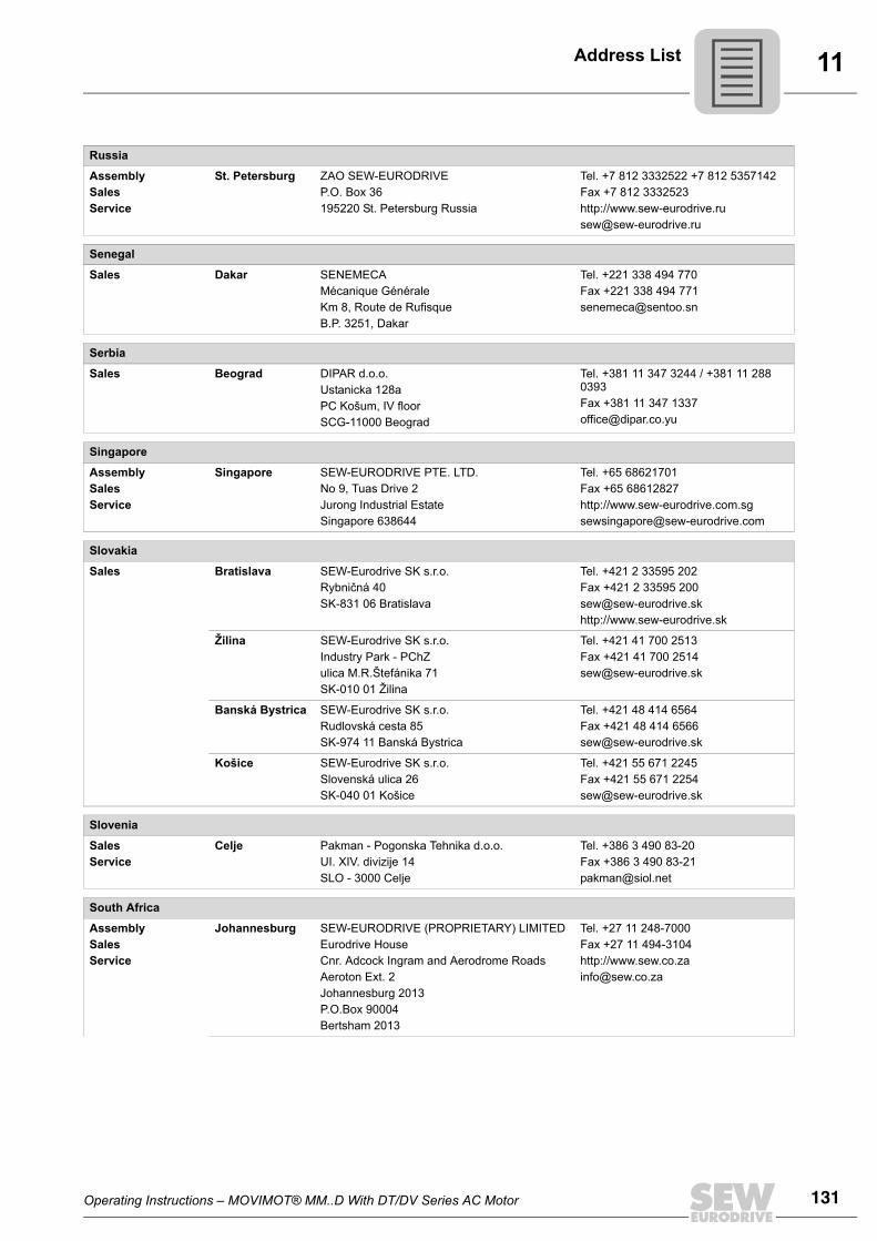
Operating Instructions – MOVIMOT® MM..D With DT/DV Series AC Motor 131
11Address List
Russia
AssemblySalesService
St. Petersburg ZAO SEW-EURODRIVE P.O. Box 36 195220 St. Petersburg Russia
Tel. +7 812 3332522 +7 812 5357142Fax +7 812 3332523http://[email protected]
Senegal
Sales Dakar SENEMECA Mécanique GénéraleKm 8, Route de Rufisque B.P. 3251, Dakar
Tel. +221 338 494 770Fax +221 338 494 [email protected]
Serbia
Sales Beograd DIPAR d.o.o.Ustanicka 128aPC Košum, IV floorSCG-11000 Beograd
Tel. +381 11 347 3244 / +381 11 288 0393Fax +381 11 347 [email protected]
Singapore
AssemblySalesService
Singapore SEW-EURODRIVE PTE. LTD. No 9, Tuas Drive 2 Jurong Industrial Estate Singapore 638644
Tel. +65 68621701Fax +65 68612827http://[email protected]
Slovakia
Sales Bratislava SEW-Eurodrive SK s.r.o.Rybničná 40SK-831 06 Bratislava
Tel. +421 2 33595 202Fax +421 2 33595 [email protected]://www.sew-eurodrive.sk
Žilina SEW-Eurodrive SK s.r.o.Industry Park - PChZulica M.R.Štefánika 71SK-010 01 Žilina
Tel. +421 41 700 2513Fax +421 41 700 [email protected]
Banská Bystrica SEW-Eurodrive SK s.r.o.Rudlovská cesta 85SK-974 11 Banská Bystrica
Tel. +421 48 414 6564Fax +421 48 414 [email protected]
Košice SEW-Eurodrive SK s.r.o.Slovenská ulica 26SK-040 01 Košice
Tel. +421 55 671 2245Fax +421 55 671 [email protected]
Slovenia
SalesService
Celje Pakman - Pogonska Tehnika d.o.o.UI. XIV. divizije 14SLO - 3000 Celje
Tel. +386 3 490 83-20Fax +386 3 490 [email protected]
South Africa
AssemblySalesService
Johannesburg SEW-EURODRIVE (PROPRIETARY) LIMITEDEurodrive House Cnr. Adcock Ingram and Aerodrome RoadsAeroton Ext. 2Johannesburg 2013P.O.Box 90004Bertsham 2013
Tel. +27 11 248-7000Fax +27 11 494-3104http://[email protected]
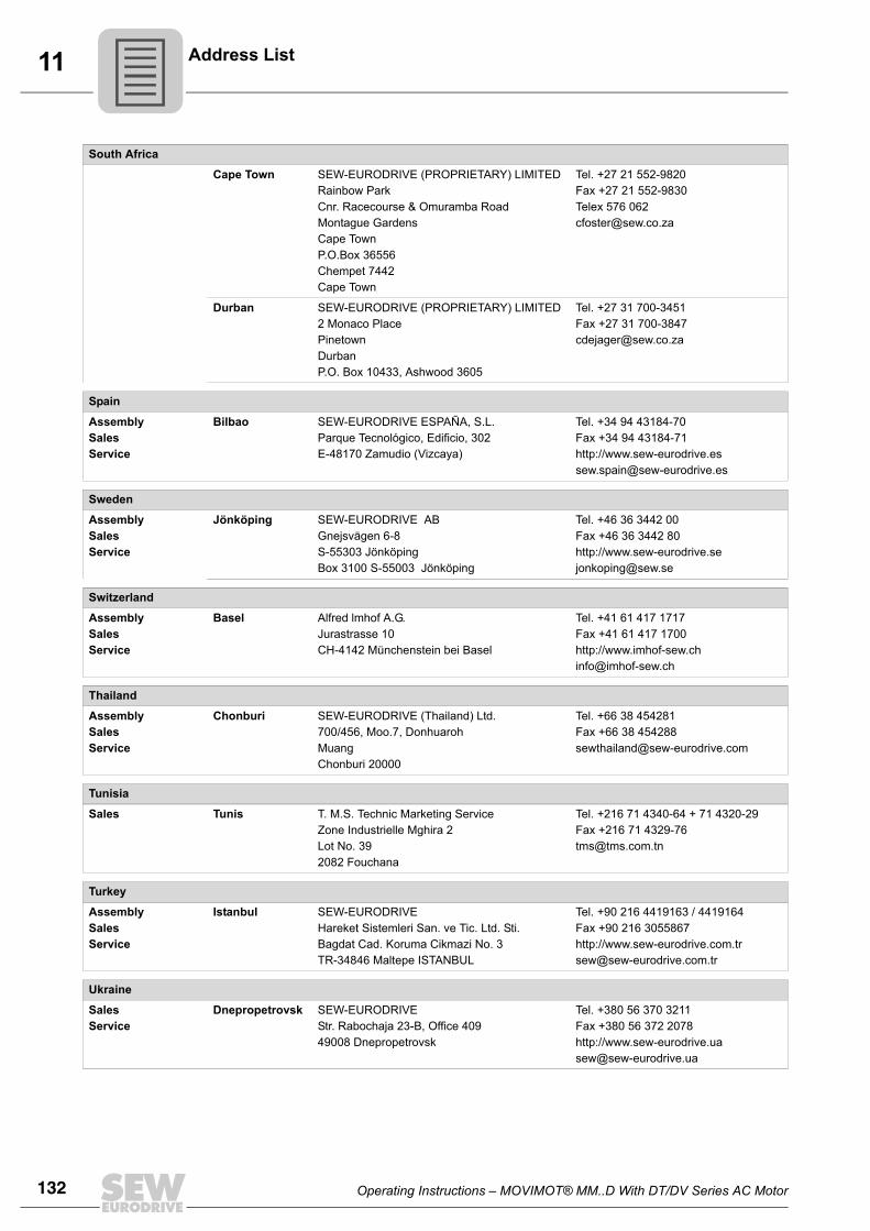
132 Operating Instructions – MOVIMOT® MM..D With DT/DV Series AC Motor
11 Address List
Cape Town SEW-EURODRIVE (PROPRIETARY) LIMITED Rainbow ParkCnr. Racecourse & Omuramba RoadMontague GardensCape TownP.O.Box 36556Chempet 7442 Cape Town
Tel. +27 21 552-9820Fax +27 21 552-9830Telex 576 [email protected]
Durban SEW-EURODRIVE (PROPRIETARY) LIMITED2 Monaco PlacePinetownDurbanP.O. Box 10433, Ashwood 3605
Tel. +27 31 700-3451Fax +27 31 [email protected]
Spain
AssemblySalesService
Bilbao SEW-EURODRIVE ESPAÑA, S.L. Parque Tecnológico, Edificio, 302E-48170 Zamudio (Vizcaya)
Tel. +34 94 43184-70Fax +34 94 43184-71http://[email protected]
Sweden
AssemblySalesService
Jönköping SEW-EURODRIVE ABGnejsvägen 6-8S-55303 JönköpingBox 3100 S-55003 Jönköping
Tel. +46 36 3442 00Fax +46 36 3442 80http://[email protected]
Switzerland
AssemblySalesService
Basel Alfred lmhof A.G.Jurastrasse 10 CH-4142 Münchenstein bei Basel
Tel. +41 61 417 1717Fax +41 61 417 1700http://[email protected]
Thailand
AssemblySalesService
Chonburi SEW-EURODRIVE (Thailand) Ltd.700/456, Moo.7, DonhuarohMuang Chonburi 20000
Tel. +66 38 454281Fax +66 38 [email protected]
Tunisia
Sales Tunis T. M.S. Technic Marketing ServiceZone Industrielle Mghira 2Lot No. 392082 Fouchana
Tel. +216 71 4340-64 + 71 4320-29Fax +216 71 [email protected]
Turkey
AssemblySalesService
Istanbul SEW-EURODRIVE Hareket Sistemleri San. ve Tic. Ltd. Sti. Bagdat Cad. Koruma Cikmazi No. 3 TR-34846 Maltepe ISTANBUL
Tel. +90 216 4419163 / 4419164Fax +90 216 3055867http://[email protected]
Ukraine
SalesService
Dnepropetrovsk SEW-EURODRIVEStr. Rabochaja 23-B, Office 40949008 Dnepropetrovsk
Tel. +380 56 370 3211Fax +380 56 372 2078http://[email protected]
South Africa
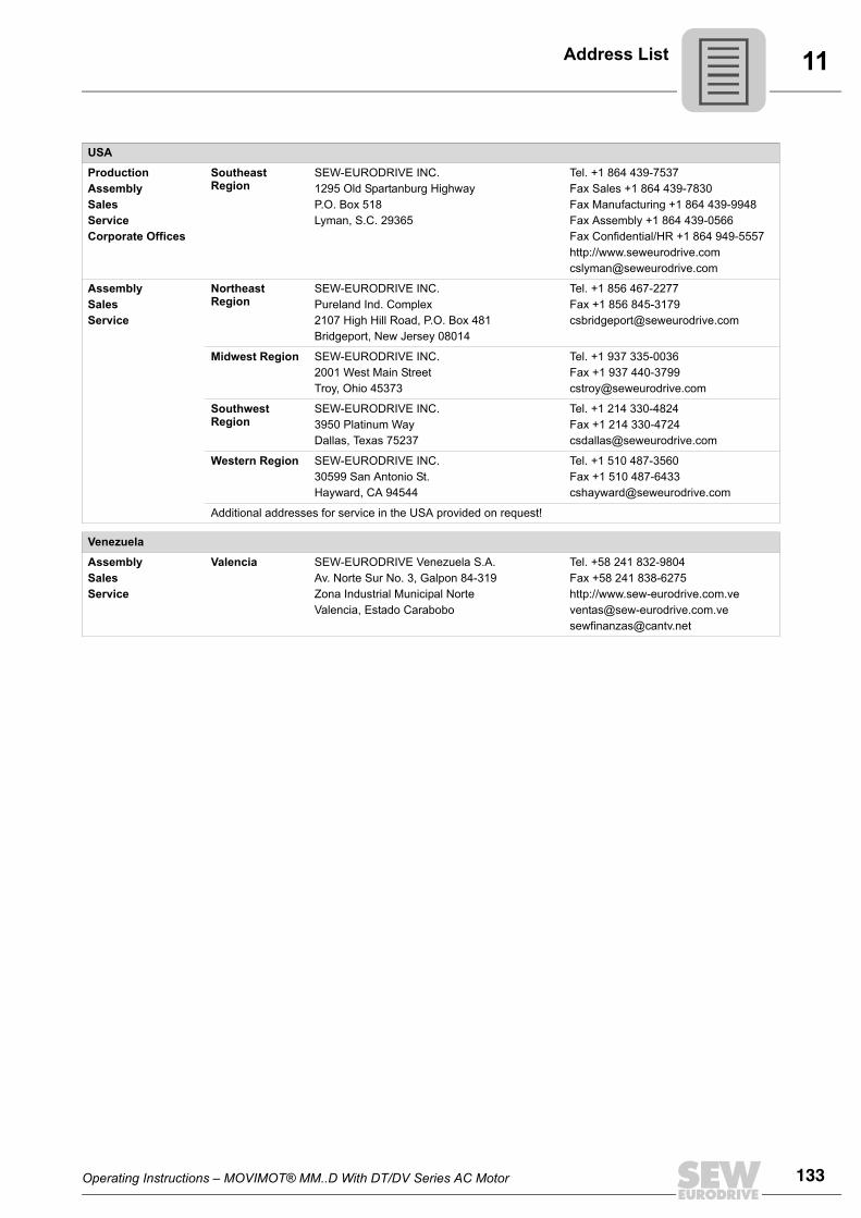
Operating Instructions – MOVIMOT® MM..D With DT/DV Series AC Motor 133
11Address List
USA
ProductionAssemblySalesServiceCorporate Offices
Southeast Region
SEW-EURODRIVE INC. 1295 Old Spartanburg Highway P.O. Box 518Lyman, S.C. 29365
Tel. +1 864 439-7537Fax Sales +1 864 439-7830Fax Manufacturing +1 864 439-9948Fax Assembly +1 864 439-0566Fax Confidential/HR +1 864 949-5557http://[email protected]
AssemblySalesService
Northeast Region
SEW-EURODRIVE INC. Pureland Ind. Complex 2107 High Hill Road, P.O. Box 481Bridgeport, New Jersey 08014
Tel. +1 856 467-2277Fax +1 856 [email protected]
Midwest Region SEW-EURODRIVE INC.2001 West Main Street Troy, Ohio 45373
Tel. +1 937 335-0036Fax +1 937 [email protected]
Southwest Region
SEW-EURODRIVE INC.3950 Platinum Way Dallas, Texas 75237
Tel. +1 214 330-4824Fax +1 214 [email protected]
Western Region SEW-EURODRIVE INC. 30599 San Antonio St.Hayward, CA 94544
Tel. +1 510 487-3560Fax +1 510 [email protected]
Additional addresses for service in the USA provided on request!
Venezuela
AssemblySalesService
Valencia SEW-EURODRIVE Venezuela S.A.Av. Norte Sur No. 3, Galpon 84-319Zona Industrial Municipal NorteValencia, Estado Carabobo
Tel. +58 241 832-9804Fax +58 241 838-6275http://[email protected]@cantv.net
134 Operating Instructions – MOVIMOT® MM..D With DT/DV Series AC Motor
Index
Index
AAdditional documentation.........................................8Additional function 1...............................................52Additional function 10.............................................65Additional function 11.............................................66Additional function 12.............................................66Additional function 13.............................................69Additional function 14.............................................73Additional function 2...............................................52Additional function 3...............................................53Additional function 4...............................................55Additional function 5...............................................57Additional function 6...............................................58Additional function 7...............................................59Additional function 8...............................................61Additional function 9...............................................62Additional functions................................................51
Setting................................................................50Address range........................................................95AMA6 .....................................................................31ASA3......................................................................31AVT1 ......................................................................31
BBGM.......................................................................74
Connection.........................................................39Installation..........................................................19Retrofitting..........................................................75Technical data..................................................119
Binary control ...................................................28, 76Block check character BCC ...................................96Brake
Braking torque..................................................122Working air gap................................................122
Brake coil, technical data .....................................122Brake control BGM.................................................74Brake rectifier BGM..............................................119Brake release without enable.................................48Braking resistors
external ............................................................123Internal .............................................................123
Braking torque......................................................122Bus configuration ...................................................55
CCable cross section ...............................................25Cable glands..........................................................16CCW rotation, enable ............................................30Coding of process data..........................................89Communication interface .......................................86Conductor end sleeves
MOVIMOT® standard variant ............................25Connection
BGM...................................................................39MBG11A ............................................................40MLG11A.............................................................37MLG21A.............................................................37MLU11A.............................................................36MLU13A.............................................................36MLU21A.............................................................36Motor, overview .................................................34Motor, when mounted close to the motor ..........32MOVIMOT® basic unit.......................................30MWA21A............................................................41Options ..............................................................36PE......................................................................27RS-485 bus master............................................42Safety notes.........................................................9URM...................................................................38
Control mode .........................................................50Controls .................................................................44Copyright .................................................................6Current limitation, adjustable ...........................52, 53CW rotation, enable ...............................................30
DDamp locations ......................................................16Designated use........................................................7Diagnostics
With status LED...............................................103Diagnostics interface X50 ....................................121DIP switches
S1 and S2 ..........................................................45Direction of rotation enable....................................83Disposal ...............................................................111Documentation, additional .......................................8Drive-ID module
Demounting .....................................................107Description.......................................................100
Operating Instructions – MOVIMOT® MM..D With DT/DV Series AC Motor 135
Index
EEarth-leakage circuit breaker .................................26EMC-compliant installation.....................................28Enabling direction of rotation ...........................30, 87Error display.........................................................103Exclusion of liability ..................................................6Extended storage.................................................111
FFault list................................................................104Fieldbus .................................................................86Function with RS-485 master.................................94
GGroup address .......................................................95
HHandling
Binary control .....................................................77With MLG11A...................................................101With MWA21A, setpoint generator...................102
Hoist application.................................................8, 69Hoist applications...................................................62Hybrid cable ...........................................................34
IIdentification...........................................................13Idle .........................................................................95Input contactor .......................................................26Installation................................................................8
BGM...................................................................19Close to the motor..............................................22In damp locations...............................................16Input contactor ...................................................26MBG11A ............................................................20Mechanical.........................................................15MLG11A.............................................................17MLG21A.............................................................17MLU11A .............................................................17MLU13A .............................................................18MLU21A .............................................................17MWA21A............................................................21Notes..................................................................16Turning the terminal box ..................................108URM...................................................................19
Installation altitude .................................................28
Installation close to the motorInstallation dimensions ......................................22Startup information ............................................83
Installation instructions ..........................................25Installation tolerances ............................................15Integrator ramp ......................................................44
LLED........................................................................99Line fuses ..............................................................25Lower motor power rating ......................................47Low-noise operation ..............................................48
MMains phase failure monitoring, deactivation.........66Maximal frequency.................................................44MBG11A
Connection.........................................................40Installation..........................................................20Operation .........................................................101Startup ...............................................................78Technical data .................................................120
Mechanical installation...........................................15Message processing..............................................97Message structure .................................................94Minimum frequency ...............................................44Minimum frequency 0 Hz .......................................61MLG11A
Connection.........................................................37Installation..........................................................17Operation .........................................................101Startup ...............................................................78Technical data .................................................118
MLG21AConnection.........................................................37Installation..........................................................17Operation .........................................................101Startup ...............................................................78Technical data .................................................118
MLU11AConnection.........................................................36Installation..........................................................17Technical data .................................................118
MLU13AConnection.........................................................36Installation..........................................................18Technical data .................................................118
136 Operating Instructions – MOVIMOT® MM..D With DT/DV Series AC Motor
Index
MLU21AConnection.........................................................36Installation..........................................................17Technical data..................................................118
Modular terminal box, turning...............................108Motor
Connection type .................................................83Connection when mounted close to the motor...32Enabling the direction of rotation .......................83Motor protection .................................................83
Motor protection ...............................................46, 83Motor protection using TH......................................57Motor terminal assignment.....................................35Motor type ..............................................................48Mounting close to the motor
Connection MOVIMOT® and motor...................32Unit designation .................................................14
MOVILINK® unit profile..........................................89MWA21A
Connection.........................................................41Installation..........................................................21Operation .........................................................102Startup ...............................................................80Technical data..................................................120
NNameplate
Inverter...............................................................13Motor..................................................................12Mounting close to the motor...............................14
No load vibration damping .....................................48
OOperating display ...................................................99Operating mode .....................................................50Operation
Binary control .....................................................77Safety notes .........................................................9With MBG11A ..................................................101With MLG21A...................................................101
Operation, low-noise ..............................................48Other applicable documentation ..............................8
PPaint protection cap .........................................43, 86Paint protection film .........................................43, 86PE connection........................................................27Plug connectors .....................................................31
Process dataProcess input data .............................................91Process output data...........................................90
Protection devices .................................................29PWM frequency ...............................................48, 58
RRamp times............................................................44Ramp times, extended...........................................52Rapid start / stop....................................................59Rapid start / stop and motor protection using TH ..66Rated voltage.........................................................25Relay output...........................................................74Replacing MOVIMOT® ........................................106Replacing units ....................................................106Request message..................................................98Response message ...............................................98Right to claim under limited warranty.......................6RS-485
Address range ...................................................95Connection RS-485 bus master.........................42Function with RS-485 master ............................94Group address ...................................................95RS-485 address, selection.................................46RS-485 interface................................................29Technical data interface...................................121User data type ...................................................95
SSafe disconnection ..................................................9Safety functions .......................................................7Safety notes.............................................................7
Electrical connection............................................9General information .............................................7Installation............................................................8Operation .............................................................9Storage ................................................................8Structure ..............................................................5Transportation......................................................8"Easy" startup ..............................................43, 86
Service.........................................................103, 110Setpoint f1..............................................................44Setpoint potentiometer f1.......................................44Setpoint stop function ..........................................102SEW Service........................................................110Slip compensation, deactivated .............................73Speed monitoring...................................................50Speed monitoring, extended..................................69
Operating Instructions – MOVIMOT® MM..D With DT/DV Series AC Motor 137
Index
Start delimiter .........................................................95Startup ...................................................................43
MOVIMOT® with fieldbus interface....................86Note for installation close to the motor...............83With binary control .............................................76With MBG11A ....................................................78With MLG11A.....................................................78With MLG21A.....................................................78With MWA21A....................................................80
Status display.......................................................103Storage ....................................................................8Structure of the safety notes ....................................5Supply system leads ..............................................25Switch f2 ................................................................44Switch t1 ................................................................44
TTarget group ............................................................7Technical data
MOVIMOT® 230V / 50Hz ................................116MOVIMOT® 400 V / 50 Hz or 400 V / 100 Hz .112MOVIMOT® 460 V / 60 Hz ..............................114Options.............................................................118
Tightening torqueFor MOVIMOT® terminals .................................24
Tightening torques .................................................23Timeout monitoring ................................................95Torque, reduced.....................................................65Transportation..........................................................8Turning the terminal box ......................................108
UUL-compliant installation
MOVIMOT® with AS-Interface...........................29Unit designation
Inverter...............................................................13Motor..................................................................12Mounting close to the motor...............................14
Unit identification....................................................13Unit structure..........................................................10URM
Connection.........................................................38Installation..........................................................19Technical data..................................................119
VVoltage relay URM...............................................119
WWorking air gap....................................................122
0 ... 924 V supply ............................................................28


SEW-EURODRIVE—Driving the world
SEW-EURODRIVEDriving the world
www.sew-eurodrive.com
SEW-EURODRIVE GmbH & Co KGP.O. Box 3023D-76642 Bruchsal/GermanyPhone +49 7251 75-0Fax +49 7251 [email protected]


![SEW Eurodrive MOVIMOT with DT/DV Motors Operating · PDF fileThe operating instructions are an integral part of the product and contain ... 1.2 Structure of the safety notes ... [1]](https://img.pdfslide.us/doc/110x75/5a9e2b2e7f8b9a6a218baa02/sew-eurodrive-movimot-with-dtdv-motors-operating-operating-instructions-are-an.jpg)