Embed Size (px)
Citation preview

......
MINING AT GOLDSTREAM
BY
R. B. HUMPHREY*
PREPARED FOR PRESENTATION
AT THE
DISTRICT 6 MEETING
OF THE
CANADIAN INSTITUTE OF MINING AND METALLURGY
*CHIEF ENGINEER,
MACLAREN FOREST PRODUCTS,
GOLDSTREAM MINING DIVISION.
SMITHERS, BRITISH COLUMBIAOCTOBER 26th - 29th, 1983.

TABLE OF CONTENTS
PAGE
ABSTRACT 1
1.0 INTRODUCTION 2
2.0 GEOLOGY OF GOLDSTREAM MINE 3
2.1 Geometry and Sequence 3
2.2 Description of the Deposit 3
3.0 SERVICES 4
3.1 Power 4
3.2 Water Supply 4
3.3 Propane 5
3.4 Compressed Air 5
3.5 Sewage System 6
3.6 Manpower 6
3.7 Ore Processing 7
4.0 OPEN PIT MINING 10
5.0 UNDERGROUND 12
5.1 Main Accesses and Seryices 12
5.2 Mine Development 13
5.3 Equipment 13
5.4 The Mjning Method 16
6.0 CONCLUSION 21
LIST OF ILLUSTRATIONS 22

ABSTRACT
The Goldstream copper-zinc property is located 93 kilo
meters north of Revelstoke in South Eastern British'Columbia.
(Figure 1) The known ore reserves of four million tonnes will
maintain a production rate of 1360 metric tonnes per day for
eight years.
This paper describes the Goldstream property with emp
hasis on the underground mining method termed "Step Room
and Fill".
-1-

1.0 INTRODUCTION
Maclaren Forest Products, a division of Noranda Mines
Ltd., is currently operating the Goldstream copper zinc prop
erty. The property includes a small open pit, an underground
mine, service buildings, a campsite, a concentrator and a
tailings pond. (Figure 2)
The Goldstream deposit was discovered during the const
ruction of a logging road in 1972. The first claims were
staked by Frank King, Gordon Bried and Bruce Bried in 1973.
Noranda Exploration optioned the property in 1974 and com
pleted 8900 metres of surface diamond drilling in 1975. In
1976, 1100 metres of drifting and 2250 metres of underground
diamond drilling took place. Subsequent feasibility studies
were carried out from 1977 to 1979 and the decision to proceed
with development and construction was made in 1980. The first
concentrate was produced in May of 1983.
-2-

2.0 GEOLOGY OF GOLDSTREAM MINE
2.1 Geometry and Sequence
The deposit lies within a sequence of metamorphosed
and deformed sedimentary and volcanic rocks. The shape is
that of a "flattened rod" or "ruler" and although it occurs
concordantly with the surrounding rock units and at a part
icular stratigraphic horizon, it rakes across the dip of the
other units.
The general sequence of rocks encountered from hanging
wall to footwall is as follows; dark banded phyllite, garnet
zone, grey green phyllite, massive sulphides, grey green
phyllite and metamorphic limestone. (Figure 3)
2.2 Description of the Deposit
The deposit consists of a single continuous bed of mass
ive and disseminated sulphides varying in thickness from one
to fifteen metres. The average thickness is three metres. The
strike length varies from 340 metres at the outcrop to 180
metres at depth. The average dip is 33°. The rake is 45° off
·of true dip. The hanging wall and footwall contacts roll on
dip as well as on strike. The down dip length is open but prov
en to 1050 metres in length.
The zone outcrops at the 920 metre elevation on the north
side of the valley. The Goldstream River crosses over the dep
osit at the 645 metre elevation. The valley slope is covered
by four to six metres of glacial till with up to 30 metres
of boulders and gravel in the valley bottom.
-3-

3.0 SERVICES
3.1 Power
B. C. Hydro constructed a 69,000 volt hydro line from
Mica Dam to Goldstream. The line parallels highway 23 to
the Goldstream Valley and then follows the valley to the
Mine Site. The twin 400 KW Cullen Detroit diesel generators,
that supplied power during construction, have been maintain
ed on standby.
3.2 Water Supply
The supply of fresh water has been a major problem at
Goldstream since the beginning of construction. It was not
anticipated that this would be a problem as the mine is in
the Interior Rain Belt with an average annual precipitation
of 1.15 metres. Several wells were drilled in high potential
areas and all hit water but not in the quantities required
by the concentrator. The Goldstream River could supply the
necessary quantity of water but during spring run off the
quality of water is poor. The major creeks on the south
.slope of the valley were tested for supply. The closest
creek large enough was sourced 1.5 kilometres east of the
mine site and can only supply sufficient water for about
10 months of the year.
Therefore, a dual system was established usi~g the East
Creek for the majority of the year and the Goldstream River,
when it is clear. (Figure 4) A filter bed was constructed
beside East Creek with a 15 centimetre sclair line gravity
-4-

feeding the 110,000 litre head tank located above the con
centrator. This system can supply the mill and mine for the
majority of the year without pumping. During low water per
iods the Goldstream River is relatively clear. A pumping
system was installed below the concentrator beside the Gold
stream. This system can supply the entire plant as a backup
source but will normally only be used for the concentrator
during low water season.
3.3 Propane
Propane is used in large quantities in most areas of
the mine site. To eliminate the requirement for several
small tanks, an underground grid system was installed. A
68,000 litre tank was placed at the 770 portal area. This
is the site of the main mine ventilation station and the
largest propane consumer, the mine air heaters. (Figure 5)
The grid system distributes propane to the compressor room
mine air heater, the main service building and the concent
rator. The propane vaporizer and a cylinder fill facility
are also located at 770.
3.4 Compressed Air
The compressed air requirements for the site are prod
uced in a compressor room located just inside the 700 portal.
~he compressors are two Atlas Copco ZRS-B units and two Gar
dner Denver EAYPT 400 units with provisions for a third Gar
dner Denver. The four installed units can supply 8,000 CFM
at 110 PSI.
-5-

The compressed air IS piped from the compressors to an
abandoned drill drift used as an air receiver. A 1.2 metre
thick concrete wall was constructed at the entrance to the
drill drift to give approximately 2000 cubic metres storage
capacity. (Figure 6)
The compressors are cooled by a closed circuit glycol
system. Fluid cooling towers were erected on surface above
the compressor room to cool the glycol in the summer. The
glycol is used to heat the fresh air supply to the compre
ssor room and the main service building shop in the winter.
3.5 Sewage System
Two identical and independent sewage collection and
treatment systems are used. One is located at the mine site,
and the other at the mancamp. The sewage plants are rotating
biological discs for primary treatment and a subsequent drain
age field for final disposal. (Figure 7)
3.6 Manpower
Goldstream will have between 180 to 200 employees. (Fig
ure 8) Presently about half live in the Goldstream camp and
half commute daily from Revelstoke.
The camp is located five kilometres west of the mine
site. The housing units are two story bunkhouse facilities
connected to a central recreation dining complex by covered
walkways. This camp will accommodate 120 people. (Figure 9)
-6-

The employees that commute from Revelstoke are tran
sported in 8 passenger vans which are supplied and maintained
by the Company. Employees are not charged for transportation
and are not paid for travelling time.
3.7 Ore Processing
The crushing and screening plants are located at the
632 metre elevation. The primary crushing unit is a 36" x
48" jaw crusher which breaks the are to minus 6". The prim
ary crushed ore is conveyed to a 5' x 10' rod deck screen
set at minus 5/8". The screen is 1n a closed circuit with a
5~' shorthead cone crusher. The minus 5/8" material is con
veyed to a 4800 ton fine ore bin for storage. Ore is reclai
med from the bin via a slot feeder and conveyed directly to
the concentrator. (Figure 10)
The concentrator building 1S located below the main
service building at the 660 metre elevation. (Figure 11 & 12)
The primary grind is obtained in a rod mill and a ball mill
in a closed circuit with cyclones. Copper and zinc regrind
mills are used for further liberation, as required. The
grinding circuits were designed to give 85% minus 200 mesh
at 60 tonnes per hour. The flotation process uses 7450 cubic
feet of conventional flotation cells. The largest cell is 100
cubic feet and the smallest is 25 cubic feet. Two concen
trates are produced, copper and zinc. Thickening is by con
ventional gravity thickeners. Further dewatering takes place
-7-
A seepage collection system and pumping facility at the
west dam will return the water back to the tailings pond.
Future dam construction will be staged as required to pro
vide sufficient storage, 2 to 3 years, at any time during
the life of the operation.
Interception and diversion of surface water flows
have been achieved by constructing ditches on the south side
of the area. Flows to the east and north are naturally diver
ted from the area by Brewster Creek and the local divide.
Water, as required, will be returned to the mill for
re-use via a reclaim pump system. Excess water resulting from
precipitation will be discharged as necessary from the impound
ment area to natural drainage flowing:-,t;o the Goldstream. The
quality of the water discharged to the environment will be
monitored on a regular basis.
-9-
4.0 OPE~ PIT
A small open pit, located above the main service build
ing (Figure 11), is being used to mine the top 70 metres of
the orebody. This method ensures recovery of the upper part
of the are that would not be totally recoverable by under
ground methods.
The pit are is in the form of a thin lense with an aver
age strike length of 300 metres, an average width of 2 to 8
metres and an average dip of 40°. The reserve contained in
the pit is 424,000 diluted tonnes at 4.08% copper. The tot-
al waste stripping will involve 1.2 million tonnes which is
being dumped two kilometres east of the pit. The overburden
stripping involved 160,000 cubic metres and was disposed of
on roads and with the waste.
An interceptor ditch was dug around the top of the pit
and the overburden was sloped back at 30°. A 15 metre wide
safety berm was cut in waste above the ore outcrop. The pit
design calls for mining ten 7.5 metre benches, along the
footwall contact. The hanging wall will be mined on a 45°
slope with 7.5 metre berms. (Figure 14) Access to the pit is
from both the east and west ends. (Figure 15) Ore is dumped
into the pit ore pass to the 700 metre level underground
and handled to the main ore pass.
-10-
The ore has proven to be extremely hard to fracture,
while the waste is relatively easy. The drilling patterns
use all verticle holes. The ore is drilled on a 1.5 metre
square pattern using 6 centimetre holes. The waste is drill
ed on a 3.6 metre square pattern using 10 centimetre holes.
Current practice is to blast the holes containing all waste
first and remove to the waste pile. The remaining waste is
blasted with the ore and is visually separated by the load
er operator with a geologists instructions.
The footwall is scaled as required. Rock bolts are in
stalled in the footwall on a 3 metre square pattern, except
where wall conditions warrant additional support. The bolts
used are 2.5 centimetre rebar grouted in place. The holes
are drilled with the production drills.
The equipment used in the pit is as follows:
Drilling
Trucks
'Loaders
Dozers
1 - Atlas Copco ROC 810 H Hydraulic
1 - Tamrock Fixtrack DH
4 - Caterpillar 769C
2 - Caterpillar 988B
1 - Caterpillar 930
2 - Caterpillar D8K - 1 ripper
- 1 winch
Miscellaneous - 1 - Caterpillar 14G Grader
1 - JCB 3D 111 Loader-Backhoe
-11-
5.0 UNDERGROUND
5.1 Main Accesses And Services (Figure 16)
The main access to the mine is via two portals at the
700 metre elevation. One portal is a service portal and one
is a man access way.
The access to the crusher, fine ore bin and main sumps
lS from the 672 portal. The 660 portal is the conveyorway to
the mill.
The portal at the 770 elevation is the main ventilation
intake and the portal at the 830 elevation will be the main
ventilation exhaust. (Figure 17)
The basic ventilation scheme is to intake 240,000 CFM
at the 770 portal down raises on the east side of the mine
distributed through the stoping areas and haulages, then
exhausted out a ramp system on the west side of the mine to
the 830 portal. The compressor room and crusher station are
supplied with fresh air from the compressor raise. This system
is isolated from the rest of the mine. (Figure 18)
An electrical distribution system has been installed
throughout the mine. The main transformers are at the crusher,
in the compressor room and by the 770 ventilation station.
The ore development transformer is in a station at the west
end of 715 drift. This transformer feeds most of the electric
mining equipment like the electric jumbos and fans.
-12-
- ,,
Water is supplied underground, from the main head
tank~ through the main service building to a booster pump
located in the compressor room. The underground distribution
system is via five and ten centimetre victaulic lines.
Compressed air is piped from the receiver drift, des
cribed in section 3.4, throughout the mine in twenty, fift
een or ten centimetre victaulic lines as required.
5.2 Mine Development
The orebody is accessed from the hangingwall by 5 metre
x 3.5 metre crosscuts on 60 metre intervals. Sills are driven
on strike at these horizons along the hanging wall contact~
to the east and west limits of the ore zone. They are 4 met
res wide by 3 metres high with a shanty back for ground con
trol and to provide room for vent tubing. (Figure 19)
A footwall ramp system on the west side of the are zone
has been developed to provide equipment access and for an
exhaust air route.
Raises were developed on the east side of the ore zone
.to provide fresh air and an emergency escape way.
5.3 Equipment
Goldstream has been planned and developed as a mechan
ized mine. Only raising and some rockbolting are currently
being done using conventional airleg methods.
-13-

The equipment currently In use underground is as follows:
Drilling
Trucks
LIm
Ventilation
Miscellaneous
2 - Two Boom Jarvis Clark 1'1J1"1 2GB Air Jumbo
3 - Single Boom Tamrock Electric-Hydraulic Jumbo
1 - Single Boom Tamrock Diesel-Hydraulic Jumbo
8 - Secan Stopers
8 - Secan Jacklegs
2 - Canun Stopers
2 - Canun Jacklegs
5 - Jarvis Clark JDT 413
3 - Jarvis Clark JDT 426
8 - Jarvis Clark JS220
2 - Jarvis Clark JS500
2 - Joy 200 HP 54-26-1770 Axial Vane, Series 1000
4 Joy 60 HP 42-26-1770 Axial Vane, Series 2000
12 - Joy 40 HP 34-26-1770 Axial Vane, Series 2000
1 - Joy 20 HP 48-21-1170 Axial Vane, Series 1000
1 - Joy 20 HP 42-17-1170 Axial Vane, Series 1000
1 - D3 Caterpillar Dozer
1 - True Gunal Shotcrete Machine
1 - Nortec Alimak Raise Climber
The Jarvis Clark air jumbo and the Tamrock diesel elec
tric jumbo have been used strictly in mine development. The
Tamrock electric hydraulic jumbos are being used in stoping and
-14-

..... III,'t .-
"
its associated orc development. They have a flexible boom
that allows them to be used for rockbolting as well as for
stoping. The 1 .5 metre wide Getman carrier is snIall enough
to allow mining in a narrow twisting stope with a minimum
of dilution.
Stope mucking is with the Jarvis Clark JS, 220 scooptrams
to mill holes. The narrow width of the ore body and their
low ventilation requirements make them ideal. Development
mucking is also usually done with the JS 220s' dumping into
the JDT 413 trucks. Again size and ventilation requirements
were the deciding factors in equipment selection.
Drawpoint mucking and production retramming is done by
the JS 500 scooptrams loading the JDT 426 trucks. The main
retram from the open pit ore pass has a chute that loads the
JDT 426 trucks.
The airleg drills are used in rockbolting and raising.
The alimak raise climber is used in the larger raises over
60 metres in length. Road maintenance is done with the D-3
Caterpillar dozer. The shotcrete machine is used mainly for
construction work but also gets some use for ground control.
The 40 HP fans are the main type used for directional
ventilation in development and stoping applications. They are
used with either 0.9 metre or 1.2 metre diameter vent tubing,
depending on the ventilation requirement. The 60 HP fans
are used in the main haulage drifts, where the large equip
ment is used, with 1.2 metre diameter tubing.
-15-

~.! ,,~ ,'"
5.4 The Mining Method
The three mining blocks currently in production or
under development are 655, 715 and 770. Each of these blocks
will be mined in the same manner using the "Step Room and
Fill" method. (Figure 20)
Ore block development is started by driving a ramp in
ore from the extreme west end of the top level breaking thro
ugh into the bottom level. This ramp 1S driven with a shanty
back at 4 metres wide by 3 metres high, down at 17% grade.
Access must be maintained around the ore ramp collar on the
sill horizons. Therefore, a footwall slash is required. The
ramp is started by benching the floor of the sill and slash
ing the wall to the hanging wall contact. (Figure 21) The
line of the ramp is under geological control.
Great care must be taken not to break the hangingwall
contact. Whenever this has happened, ground conditions have
been poor. When the ramp face is 4 - 5 metres wide, a pillar
is established between the sill and the ramp. At this stage
the ore ramp is driven like any other ramp, except the line
is under geological control. A geologist usually marks up
each round, but the shifters and miners soon gain expertise
at defining the ore-waste contact.
A vertical drop is left from the ramp benching. This
is a potential safety hazard and requires a safety fence.
They are usually constructed: from 20 centimetre timber.bolt
ed to the back and concreted to the floor.
-16-

Tbe ore ramps average 350 metres in length and can
take a long time to develop. The time span can be shortened
by driving the ramp from the bottom up, as well as from the
top. A problem with this approach is in trying to connect
the two legs. The r~~p layout is never exactly known because
of the rolling nature of the hangingwall. Therefore, the
ramps are connected by either adjusting the grade near break
through or they are connected with a strike sublevel.
An ore haulage drift is driven on the bottom level par
alleling the ore ramp. (Figure 22) Drawpoints are cut from
this haulage and 1.5 x 1.5 metre mill hole raises are driven
to the ore horizon near the are ramp. This work is completed
as early as practical so that the mill holes can be used for
stope development as well as production. Ore is picked up
in the drawpoints by 5 yard scooptrams and loaded into 26 ton
trucks. All ore is hauled to the main ore pass on 700 level
which feeds directly to the crusher.
The are ramp splits the are block into east and west
stoping areas at about a 75 - 25 ratio.
The east mining block is divided into stapes with sub
levels at 10 - 12 metre elevation intervals and with internal
ramps at 50 - 70 metre strike intervals. The sublevels are
driven with a slight upgrade, three metres high and three
to five metres wide. If the are is wider than five metres,
then the footwall contact will be found by test holing and
the remaining are will be left for slashing at a later date.
In narrow areas, the sublevels are driven three metres wide
with a shanty back to facilitate vent tubing. (Figure 23)
-17-

The sublevels must be turned off the main ore ramp in
such a manner that ramp access can be maintained. Wall slash
ing is started at the d~signed sublevel elevation in the ore
strike direction at the grade of the ramp. When the ramp plus
slash, is eight to ten metres in width a pillar is established.
(Figure 24) Since the sublevel has dropped below the designed
elevation, it is brought back to proper grade as steeply as
possible. The sublevel is driven the extent of the ore zone,
under geological control, following the hangingwall contact.
The strike length of each sublevel will determine the number
of stopes there will be at that horizon. The locations of the
internal ore ramps are chosen with the most easterly one
being driven first. Pipe and vent ducting are removed beyond
the ramp collar. Access on the sublevel beyond the beginning
of the ramp bench is lost but is no longer required. The ramp
is started in the same manner as the main ore ramp, by bench
ing the floor and slashing the wall under geological control.
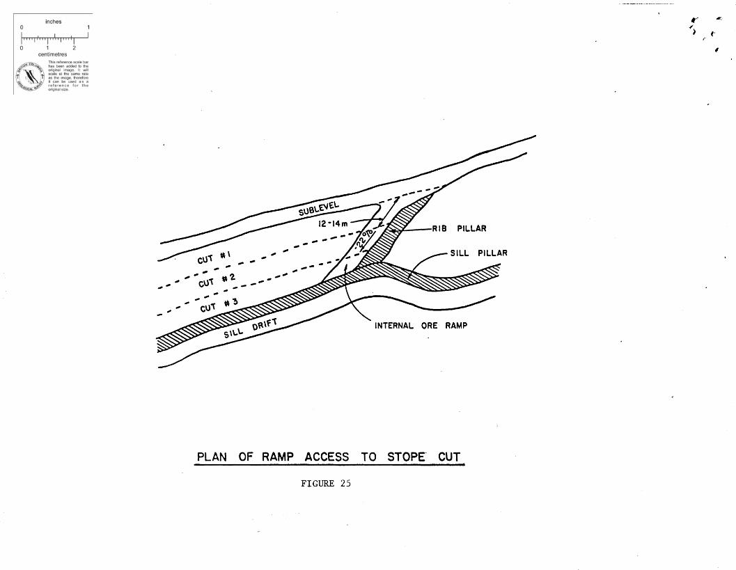
The internal ramp is 22% because of the short ramp length
involved. It is driven 12 to 14 metres or just enough to give
access to the first 2.5 metre cut in the stope. (Figure 25)
Each cut is benched at a slight upgrade to the full width of
the ore. The cuts are advanced in three metre horizontal ben
ches to the ore limit in the end stope or to a rib pillar in
an internal stope. The benches are drilled as a slash without
a cut. (Figure 26) Each cut is accessed in the same manner
by advancing the internal ore ramp.
-18-

Ground control is carried out as close to the mining
face as practical. Current practice is to use 1.8 metre
split sets on a 1.4 metre pattern. Longer bolts, 2.4 split
sets and rebar are used as required. Swellex bolts are curr
ently being tested. They are attractive because the hoJes
can be drilled with the stoping jumbo and the bolts can be
installed later in a remote fashion. This routine more effic
iently matches the mining cycle.
Stopes are mined in the manner discussed from the bot
tom of a block up and from the east end of the are zone in
towards the main ore ramp. (Figure 27)
Sill and rib pillars are left for ground support until
the stope can be backfilled. The backfill plant is currently
being designed and is scheduled for use in the summer of 1984.
The fill sequence will be from the bottom up and from
the main ramp east. The sequence is such that it will poten
tially allow for all rib and sill pillar recoveries. (Figure
28) A stope will be prepared for fill by building fill fences
and drainage towers. The stope will be flood filled as tight
to the back as possible. The sill pillar above the filled
block can then be removed as can the rib pillar to the east
of the filled stope. All pillar recovery must be from above
or beside a filled stope as cemented fill is not being planned.
-19-
The mining method to be used for the 25% of the ore
zone that is west of the main ore ramp will be similar to
that on the east side. A permanent barrier rib pillar will
be left below the are ramp for ground support and to make
the mining of the east and west sides independent of each
other.
The main difference in mining the two areas is in the
method of access. Access to the west stopes is from the foot
wall ramp system. Short ramps or crosscuts are driven to int
ersect the ore horizon at the designed sublevel elevations.
The sublevels and internal ore ramps are driven in the same
manner as on the east side. The ore on this side is narrower
so the pillars will be less attractive to recovery. There
fore, the stopes are designed for a larger size to try and
extract a higher percentage of ore in primary mining. Fill
ing and pillar recovery will be sequenced from the footwall
ramp to the barrier pillar and from the bottom up. Recovery
of ore remnants and pillars will depend on the economics of
each individual block. (Figure 29)
Production requirements from each stoping block will
be 12,000 tonnes per month. During the pit operation, two
stoping blocks and development ore from a third, are requi
red. At the end of the pit production, three stoping blocks
and development in a fourth, will provide the total mine
production required.
-20-

6.0 CONCLUSION
Construction and development of Goldstream took place
at a time of severe economic recession in the' mining indus
try. It was recognized from the beginning of the Goldstream
Project, that in order to be profitable in the 1980's, it
must be a very efficient operation. This fact was one of
the main reasons for the automation of the concentrator
and the use of a highly mechanized mining method.
It is the belief of Goldstream Management that a high
degree of employee involvement in decision making will also
add substantially to the efficiency of the operation.
The project was a very welcome addition to the Revel
stoke area where unemploYment levels are high. It will also
help to reduce the economic downturn of the Revelstoke Dam
completion.
The total capital and preproduction costs were $71,200,000.
(Figure 30) Ongoing capital projects will include the backfill
plant, raising the tailings dams and deep ore development.
-21-

LIST OF ILLUSTRATIONS
FIGURE 1 - LOCATION MAP'
FIGURE 2 - GOLDSTREAM CLAIM BOUNDARY
FIGURE 3 - GOLDSTREAM ROCK UNITS
FIGURE 4 - GENERAL SURFACE PLAN - WATER LINE LAYOUT
FIGURE 5 - GENERAL SURFACE PLAN - PROPANE LINE LAYOUT
FIGURE 6 - COMPRESSED AIR SYSTEM
FIGURE 7 - SEWAGE TREATMENT - GENERAL ARRANGEMENT
FIGURE 8 - GOLDSTREAM WORKFORCE PROJECTION
FIGURE 9 - GOLDSTREAM CAMP - GENERAL LAYOUT
FIGURE 10 - GOLDSTREAM GENERAL PROCESS FLOW DIAGRAM
FIGURE 11 - GENERAL SURFACE PLAN
FIGURE 12 - GOLDSTREAM CONCENTRATOR - GENERAL ARRANGEMENT
FIGURE 13 - WEST TAILINGS DAM SECTION
FIGURE 14 - TYPICAL SECTION OF OPEN PIT
FIGURE 15 - OPEN PIT PLAN
FIGURE 16 - UNDERGROUND SERVICE AREA - GENERAL ARRANGEMENT
FIGURE 17 - VERTICAL SECTION OF UNDERGROUND DEVELOPMENT
FIGURE 18 - UNDERGROUND VENTILATION SCHEMATIC
FIGURE 19 - CROSS SECTION OF SILL DRIFT
FIGURE 20 - GOLDSTREAM ORE SILL DEVELOPMENT
FIGURE 21 - PLAN OF ORE RAMP COLLAR
FIGURE 22 - PLAN OF ORE BLOCK DEVELOPMENT
FIGURE 23 - CROSS SECTION OF SUBLEVELS
FIGURE 24 - PLAN OF SUBLEVEL COLLARED OFF ORE RAMP
FIGURE 25 - PLAN OF RAMP ACCESS TO STOPE CUT
FIGURE 26 - CROSS SECTION OF STOPE BENCHING
FIGURE 27 - MINING SEQUENCE OF THE EAST ORE BLOCKS
FIGURE 28 - FILLING AND PILLAR RECOVERY SYSTEM SEQUENCE
FIGURE 29 - MINING OF WEST ORE BLOCK
FIGURE 30 - CAPITAL AND PREPRODUCTION COSTS
-22-

..
K'LO~1ETERS
FROM REVELSTOKE TO
GOLDSTREAM 93MICA DAM 137KAMLOOPS 209
\···-:~--!r'.~... .:r.lfkon NWT'l / III \ ._- •.• _ •.. _ ••••-=-:..--..,. .'. B.C. :
\ .'. I
I·:0u·-
ail.t:<iJ
LOCATION MAPFIGURE 1
1I
f
iI
"!!II

>0::<
toz::>oCD~<t-JU~«w0::...eno-Jo(!)
enwz~«cz«0::oZ
I/)
/---------
C'-
67
'0lI.'
,~
-:;;
m~
I:~;
/"
,-
--1-,I'~
---
-----"
---II
'Y'
'l\99
J:)
~SD3
II.
I'L
,I
tI,
---.,I
H\
/'I
,1\rV
1";
L...j
.,'"
,............
.,'I
---
i,
g~
I,I,Ir
.~
!/
I~/
•CJ~"
,
I,~~
•~e,1'
I~~",;'
L)~
.,/
\,t
·7 /'
~\
,.
~\•\.\\•
..,),~
..""..~
I•I•(.\.\
~j
·r'
'\
,\,\.\•\....
\\)\~J
....-If'
"

IIIII----SILICEOUS CHLORITE- BIOTITE PHYLLITE, + 5Cm
--- DARK CARBONACEOUS AND CALCAREOUS PHYLLITE, 200 -250m
GARNET ZONE, 5 -15m
~ SERICITE PHYLLITE, 5-IOm
---- MASSIVE SULFI DE, 1- 8m
~~~_~i ~""'-SERICITE PHYLLITE, 5-iOm
'" BANDED LIMESTONE, 10-20m
INTERLAYERED SERICITE-BIOTITE CHLORITE PHYLLITE, +50m
GOLDSTREAM ROCK UNITS
FIGURE 3
"f .. , ..

'-'-. ---.--
To Waste dump
To r:ast Creek f';:;:.f= Y" niter~
FIGURE 4
,.,,,I
I,/
I/,
I/,
/,,,/,
/,,/,,,,,
/.,,,,
GENERAL SURFACE PLANWATER LINE LAYOUT
" ~==:::::i~=====::::J1,/,,
//,,,
/,/,
/," ORE BODY,,,,,,,,
IJ~
~
II,I
•II
............. ~
~," ;,"<.~"'", .
" ~, .770 portol-!-WMain Ventilatio~
I Station .~I
J~,
,/
//,,
II,
//
/,/
/,
OPEN PIT AREA
~.'er~
,/
//
/(,I

To Waste dump
To East Creek= filter bed.
FIGURE 5
CYLI NDER FILL BUILDING
",,/
II
I/
/~,,,,,,,,,
I.f,,,,
I,,,,,J,,
GENERAL SURFACE PLANPROPANE LINE LAYOUT
,.......... '". I
,,~, "
f \, '.
f \
\
IJ
I,I,,•III
", .., I 18,000 US GAL. PROPANE TANK
~~'-;( ;~_ ..., ., /--.....--I " gh,t---~:-VAPORIZER, t··
770 portal~MainVentilationI Station
I 18 Mil. BTU/HRJ MINE AIR HEATER,,
",,-
..::...:~:.:.:.:.;.-:B=-T,:,,::U::..l,/..:..H:.:.:.R GAS HEATER
o Sewage field
/./.,
//,
/.I
/,,,I,,
/,/,
/~
0·9 Mil. BTU/HRMAKE - UP AIR HEATER
,, Pit
//
" OPEN PIT AREAII
./oncentratI &'ildinO
AI B RECElyER ORJ FT2000 M3 CAPACITY
I- 2 M CONCRETE BULKHEAD
25 CM AIR LINE
COMPRESSED AIR SYSTEM
Figure 6
";,.. t,
•
GLYCOL LINE
COMPRESSOR ROOM2-ATLAS COPCO ZR582 - GARNER DENVER EAYPT 400
.. 700 PORTAL~r .....
SERVICE
~ ~BUILOING
2-15CM GLYCOL LINE
-.

#1
#;
.; f,4
I. 100 FT. ·1I
~SEWAGE DRAIN FIELD_ 4" PERFORATED PIPES"--
t-U.
0IX)
- '1]1\,-TREATMENTSEWAGE
PLANT
SEWAGE TREATMENT GENERAL ARRANGEMENT
FIGURE 7

,
GOLDSTREAM WORKFORCE PROJECTION
STAFF HOURLY TOTAL
UNDERGROUND 5 (7 ) 42 (73) 47 (80)
OPEN PIT 2 (0) 18 (0) 20 ( 0 )
MILL OPERATIONS 13 21 34
MINE MAINTENANCE 1 20 21
MILL MAINTENANCE 1 10 11
ELECTRICAL 1 6 7
SURFACE 1 7 ( 8 ) 8 (9)
SAFETY/FIRST AID 2 4 6
WAREHOUSE 1 3 4
ENGINEERING 9 9
GEOLOGY 3 3
ACCOUNTING/PURCHASING 9 9
EMPLOYEE RELATIONS 1 1
MANAGEMENT 4 4
53 (53 ) 131 (145) 184 (198)
( ) INDICATES WORKFORCE AFTER PIT COMPLETION
FIGURE 8

t,A
..~!,.
PARKING
BUNKHOUSE .. e"
GOLDSTREAM CAMP-GENERAL LAYOUT
FIGURE 9
PARKING
= -0
=<l. =W
W
en en::::l
::::l
00
::c DINING:J:
~~
z AND z::::l ::::lm RECREATION m
COMPLEX

•
(0:
LIO~I{lhI31Rod Mill
ooI041~1131
Ball Mill
GOLDSTREAM GENERAL PROCESSFLOW· DIAGRAM
FIGURE 10
Automatic
~Pressure
o Filtero
9',
9\
, ~
,~
To East Creek filter bed= .
GENERAL SURFACE PLANFIGURE 11
I~=:::::::-==i::::====I,,,I
//,,
I,,,,,,'ORE BODY,,,,
"",,,
'1, I,,I
II
~I
~,I,
",,,,,~,,,,,,,,,,
~,,~----::=:::::::::::: ,
I,,I
I,,II,,
I~.,
~+u-:'''''' ., t'
, Main Venti a Ion770 Portal Station
II
JI,
II
830 Portal -;4;1,
"
O f ;,-'3 Sewage le.~, .
~
//
/,,,I,
I'/,
",/,
,/
//
, OPEN 'PIT AREAf,.
\
I~~.'t4"""""""'ff I~
; Powder '"
~

~
~ .. ,~
CopperConcentrate
Loadout
Boy
ZincConcentrate
LoadoutBay
-Conveyor
Conveyor
On- stream Analysera Computer Room
OLimeDissolvingTank
ZincThickenerTonk
,I,I
Off ices a Reqgent Storage Area
III
ConditionerTanks
I In J I'(Distributor l
'lL- ...l
1 I
QRearind
Rod a Ball Storage
Electrical Room @L-----------L..:~~:::::7~====~--~'\-.J,~~\:";:':;;::-;:', > ) ( ,' ( ,
GOLDSTREAM CONCENTRATOR - GENERAL ARRANGEMENT
FIGURE 12

f
,,
('
It. of Starter Dam
....._____ a.- _ _ _ _ _ _ _ _ _ _ __",-, '-
..
.-~
.....!Jj
U,;
670
680 .•
70°1I"-J&:I..u
690 - ~
I:"
.....
Silty Sand 8 Grovel( (Glacial Till 01 deplh)---J
I·Om Filter
It. of Ultlmote Dam
I !i 20'Om .1
~7·0
"
5·0 CUltimate crest el. 700·0 m
1(Subject to review)
~,.- ~.7'"
." '" ......... 2-'- /'''", ...m·m '1~"'''", ....-::-llI ~,1:..-"1~ " ~, '.... .... ~ Profi Ie of possible~ ~,' \ .... ~ future embankment
'" ~ .....2 Compacted ......~ I silty sand 8 gravel~ ..........
Compacted ~ .......tL-- silly sand 6 gravel) ....................
...
Stripped Foundation(peat deposits and otherobjectionable materialsremoved)
wtde~ln'lo.omKey Trench
Sand 8 Grovel
~TAILINGS
WEST TAILINGS DAM SECTION
FIGURE 13

SAFETYBENCH
897·5
TYPICAL SECTION OF OPEN PI T
FIGURE 14
~
~ ,
•• •, -,

Z<t
..JQ
.LJ"')--e
I-~
E15100
Q.
~0H~
ZlJJQ
.0
E1
50
00
E1
52
00
zE
14
90
0
...J
enen~LLJa:o
!::~..J
LaJ0
::o
0
enen
0
g}Q.
(7)0
o~
z
0o
et
0eta:
N
0
Z
0NZ
~15200
-;~,
El.o
go
n'
-.....
...
,I
II
/,
II
t ,,
/I"
II
l,
II
\\
,,
\
\,
\,
II
I\
\I
I,
II
II
10\
,1
6'
I,
1,
IN1
0I
, ,1 m
/N
\,
\(;;'9
I
EI5
00
0'
\\8
1
,(7)
II,
.IJ
,~II
I""'~I
I,,
I
II
III
I
I,
II
II
I1
,I
E15100
,\,
.

655~
~
To612 Porta
if
..
ToMill
No.7 Conveyor
Screen House
Main Service Drift
Crushing Station
Pass
~'~
FIGURE 16
,
CompressorRoom
Main Sump
700 Haulage
UNDERGROUND SERVICE AREAGENERAL ARRANGEMENT
100 Portal
,
Serv i ceBuilding
,
II
(I
I,I,
/I
/,
,
//
655 Access Ramp
ORE BODY
/I
//

700 M
500 M
700
Open Pit Area
ooanN
\ ,\ I~'\/ /~
\ I \\ I
I\/\\
\
II
'I'II
i'~
I II/"~C ~Qtf \~ ~C"Proposed V f""oo; ......
Y 11 Shaft '! ~ .....' II -! _
~----........
' ....... ...... .............
.,f
--...
,~
....... .........
VERTICAL SECTION OF UNDERGROUND DEVELOPMENTFIGURE 17

~
,
..f
FOOTWALLRAMP SYSTEM
~':-~-,:""~'!-':"'71~;~~r'"'~i;'~,,!,,-::~~;"""~ '---~-------,---,....---.:
BOO M
850 M
770 HAULAGE DRIFT•30,000 CFM, < <
I 60,000 CFMLaJen
750 M « :IE0::: LL.
t-U
Z 0L&J 0> 0z 0- 715 HAULAGE DRIFT« co~ -
30,000 CFM
90,000 CFM/A.~700 M 301000 CFM
L&Jen :Eex l.L
a:: U
0t- OZ 0 655 HAULAGE DRIFTw> 0
30,000 CFM ~~U ~~-t~-(O\\ ,. I 401000 CFM(j)
tt,; CO~ ~~ r~
650 M
10,000 CFM
UNDERGROUND VENTILATION SCHEMATIC
FIGURE 18

,
L&Jm::lI-....
,zw>
W£
,
I-U-
0::C.J.JU
)
lL'"
0.....
~~
~
Z0e",H~
I-0lLIU
)
..J
U)
..J
U)
<
0
~
0::
C)
0
Z(5Z4:
::I:

,
....ZW~Ct.
0...JU
J>WC
0
...JN
-J~
00~c.:J
l1JH~
0::0~«l1J0::t-OO0..J0C
)
"-...\
\\\\
\\,\
,
or()C
X)
c ..~
,\ \
\
... ."
'""
~~
,\
"\
\
,\\\
\\
\
""\
',\
\\
\\,
,
\\
\\
\\
,\
\\
\
,\,\
\\'
\
....>
-
,\
\\
,o~
\\
0
,\
\\\\
_a
l
\'\,
\'
"E
Q)
,\\\
"
-..
\\
\
..JO
\\
\\
'\.1,\
\\
\\
,,\
\',
,\\
\
..-\,
lL.
\\
\-.;
,,\.~t;
u.-\a::
\\
~\\
%"0
'\
0"
a\
\..J
0--\
\-1
~,
tt-\,..J
~,\
'1\'u
)\\C
/)
-0=.\
\(/)
<:0\\~\\
,0
u)'
,
\\o
,,\t-
~\
,0
\\
t-0
\\
to,
0\
,
(1)\\
~\,
\0'\,
\~\
......\\
\t-
\\
,\
\\
'"\
\
\\
\\
\\
\,\
\
"\,
\\
"'
\
\\
,\\
"\\
.1.=\
\
r

FOOTWALL
SLASH
PLAN OF ORE RAMP COLLAR
FIGURE 21
BENCH
WALL SLASH
SECTION "A-A"
.../
~
BENCH
,..

~
I
~
,
...
I
,
/,
/
I
/~
/',
/~
STOPI NG BLOCKJ
,/ LIMIT OFr--- ORE BODY, .
I
/
//~
,
I
/I
/ ~EAST~ ,-(
I/
,/
II
PLAN OF ORE BLOCK DEVELOPMENT
FIGURE 22

HANGING WALL
Ertl
I. 5m .1
CROSS SECTION OF SUBLEVEL
IN WIDE ORE
FIGURE 23
HANGING WALL
FOOTWALL
I' 3m----l
CROSS SECTION OF SUBLEVEL
I N NARROW ORE
t
'" ..I'
~

.....
\
\\
\\
".J:\
~\
~\
\
0
:E«Q:
LLIQ
:oU
.u..oo~<
t..J...Joo...JW>~CD:::>enlLoZ<
t..Ja.
,,,,\\\\\
,\
\\
\\\
t'I'
-\..
,....
\\
..........
';\a
::;)\
(,)\
(,)\\
,\
\,
\
\\
Q.
::::E<{
0::
lIJ0
::,o..J<
{za:lIJtoZ
....:::>oi.LJ0
oteno....enenwoo<
t
0~<
ta:u..oZ<
t-I
a.

/'",
t'""., {,
"I
HANGING WALL
CUT #2
,
;/#
/'
~
CUT # I
SUBLEVEL
FOOTWALL
#/
CROSS SECTION OF STOPE BENCHING
FIGURE 26

~-
("I
r(, WEST STOPING
BLOCK
BARRIER PILLARI
SUBLEVELS
,/(
o~~
~ ... ~~\~
,
j-LIMIT OF.ORE BODY
S\\.-\.-I 10~
CROWN PILLAR~<:( ( ( (~
RIB
MINING SEQUENCE OF THE EAST ORE BLOCKS
FIGURE 27

CROWN
RIB PILLAR -..",~--
/,
/,/
FILLING AND PILLAR RECOVERY SEQUENCE
FIGURE 28
BARRIER PILLAR
LEGEND
o FI LL SEQUENCE
o ,PILLAR SEQUENCE
:z: BULKHEAD .
•••• FILL FENCE
It" ",.f'~ J ('

l'~'·:!"i,?~':'",~,!:~:c,_- _~,~';,-.,-. - '~''''f!'t¥i.~Y;.:;;r''~''''''
BARRIER PILLAR
/ EAST SlOPING BLOCK~
SUBLEVELS
~~~~
O~<t,
~~~
S\\..\"- LeO\\Oti\ / LIMIT OF
ORE BODY
~
//
MINING OF WEST ORE BLOCK
FIGURE 29
/,
;;»,c I ORE RAMPS
SUBLEVELACCESS
t: (,#JC
I

r..·'~,>."·· '.-'·r '. ,..
iJ.. ,_.. ·... fiI
CAPITAL AND PRE-PRODUCTION COSTS
UNDERGROUND
OPEN PIT
CONCENTRATOR
DEVELOPMENT
EQUIPMENT
INSTALLATIONS
DEVELOPMENT
EQUIPMENT
10,000,000
3,300,000
5,800,000
1,300,000
1,700,000
18,000,000
GENERAL SITE AND BUILDINGS
POWER
CONCENTRATE LOADOUTS
CAMPSITE
STARTUP
PRE-PRODUCTION INDIRECTS
TOTAL
FIGURE 30
5,700,000
6,300,000
1,000,000
3,700,000
1,700,000
12,700,000
71,200,000

in Larox pressure filters obtaining three to five percent
moisture. The dried concentrates are stored on covered con
crete pads just outside the concentrator. Copper concen
trate is trucked to a rail loadout facility in Revelstoke
and loaded into rail cars for shipment to Noranda's Horne
Smelter. Zinc concentrate is trucked directly to Cominco's
Trail Smelter.
Tailings are pumped from the concentrator basement
by two parallel pumping systems up to a tailings box at
the 730 elevation. ·This control tank feeds the tailings
line, which follows a route parallel to the mine access
road, at a slope of about 0.5% to the tailings pond. It
sits on a prepared base cut into the hillside. Localized
cover has been placed on the line to protect it from minor
earth and snow slides and culvert pipes have been used to
protect the line at road crossings.
The tailings containment area is a rectangular, U
shaped valley approximately 1000 metres long and 200 metres
wide. With its natural topographic relief it was well sui
'ted to the requirements for the tailings impoundment. The
available tailings storage area is approximately 24 hect
ares to elevation 700. (Figure 2)
The tailings impoundment area required the construc
tion of two earth dams averaging approximately 19 metres
in height. The dams have been constructed as water reten
tion structures. (Figure 13)
-8-