Embed Size (px)
Citation preview

1
© 2005-2009 HYPER RACING INC. Basic Micro Sprint Setup
THE SETUP PHILOSOPHY: BASELINE CHASSIS SETUPThe baseline setup is defined as the zero point from which allchanges are made and described from. It is basic and repeatable.It is documented, and changes can be made to it, with the pur-pose of recording the resulting gain (or loss) in performance.When the setup is changed, it should be in reference to this point. Re-establish the baseline setup at the following times:•before the first time on the track each season•once every four races or more often if time allows•after an accident capable of changing the setup
This baseline setup procedure can be checked it in about tenminutes, and modified it in about five to twenty minutes. Bepatient, make notes, and fill out a setup sheet during theprocess. Once the baseline setup is in the chassis, use thesuggested adjustments on page 8 to fine tune your handling. To determine the measurements, block sizes, offsets, andangles needed for your chassis, you will need a setup sheet.The setup sheet will include the measurements you will needto complete the setup procedure. If you have a Hyper Chassis,we have very detailed settings and suggested adjustmentsthat will work for your chassis. To obtain a set up sheet foryour Hyper chassis, visit the chassis owner’s section of hyper-racing.com, and choose a setup based on track conditions, orcall the shop. If you do not have a Hyper Chassis, consult yourchassis manufacturer for a baseline setup. If this information isunavailable, use these specifications as a starting point, or visithyperracing.com, and choose a generic setup. MATERIALS• two framing squares, measuring approximately 12” x 12” atsmallest to 18” at largest
•8’ or 25’ tape measure•6” or 12” steel ruler•set up blocks (found in the Hyper Racing Catalog) or woodblocks cut square and accurate within 1/32” to the lengthsspecified below. These blocks heights will vary dependingon track conditions, chassis type, driver preferences, driverweight, and track layout.Reference your setup sheet to find the correct size blocks to use for your chassis.
•grease pencil or marker•level stands or blocks: make your own with eight 2”x4”x20”pieces of wood, use four on each end of the car
•1/4”x at least 6’ flexible tape measure (stagger tape)•Setup sheet from manufacturer or hyperracing.com
PREPARATIONThe chassis must be in a race ready condition with all boltstight and all components in place. make sure there are no bentrods, rod ends, shocks, axles, hubs, or torsion arms. With tor-sion cars make sure the bars spin freely in the bushings, youmay need to use a reamer to remove material from the bush-ings to enable the bars to move freely with no resistance.Make sure all rods can move freely and don’t bind up through-out the suspension movement. Choose a level, flat surface.Support the car by its lower frame rail on level stands orblocks as described in the materials section. The car shouldbe level and high enough for the axles to fall and to fullyextend the shocks. Place the 2-3/4” rear blocks between therear axle and the lower frame rail on the left and right sides ofthe car. Place front blocks under the front axle. The blocksensure that the axle is parallel to the frame. There should beno tension between the coil spring nuts and the coil spring orthe torsion stop jacker bolt and the torsion tube. If there is,turn the adjusters up until the springs or stops are free. Thedriver should not be in the car. The blocks will remain in placeuntil Step 9: Toe.PROCEDURE1. Bearing Carrier TimingWith the chassis raised and the 2-3/4” bearing carrier timingsetup blocks under the rear axle, place the framing square onthe floor and slide it up to the axle along side the bearing carrier. Measure the distance horizontally from the center ofthe upper rod end to the square (distance x). Then, measurethe distance from the center of the lower rod end to the square(distance y). If you have anew style bearing carrier with a bubble level in it, adjust the rod ends until the bubble is in the middle.On the 4-link suspension (250cc Hyper), loosen the jam nutson either of the control arms and turn the control arm until thespecifications listed below are achieved. On the wishbone-type chassis (600cc Hyper), remove the bolts holding the wish-bone to the bearing carrier to make adjustments. Tighten thejam nuts towards the radius rods. Move to the other bearingcarrier and repeat the procedure. For coil-over (Hyper), wishbone, and shackle-type torsion(Hyper) chassis distances x and y should be equal, makingbearing carrier perfectly level. Also at this point, make the leftside wish bone as short as possible for the Hyper chassis, thiskeeps the rear axle as far front as possible providing maximumforward bite. The right side wishbone will end up with the threerod ends extended about 1/2” to get the rear axle square.For trailing arm torsion chassis (RTS, PMP, Stallard), the top ofthe bearing carrier should be tilted toward the front 3 degrees.Distance x will be about 5/16” greater than distance y. For trail-ing arm torsion chassis with the brake caliper bolted to thebearing carrier (not on a brake floater), x and y should beequal, to keep the bearing carrier from spinning over center.
PREPARE TO WIN 2010: BASIC MICRO SPRINT SETUPBy: Mike Dicely
THIS INFORMATION IN THIS DOCUMENT MAY NOTBE REPRODUCED IN ANY WAY WITHOUT THEEXPRESSED WRITTEN CONSENT OFHYPER RACING INC.
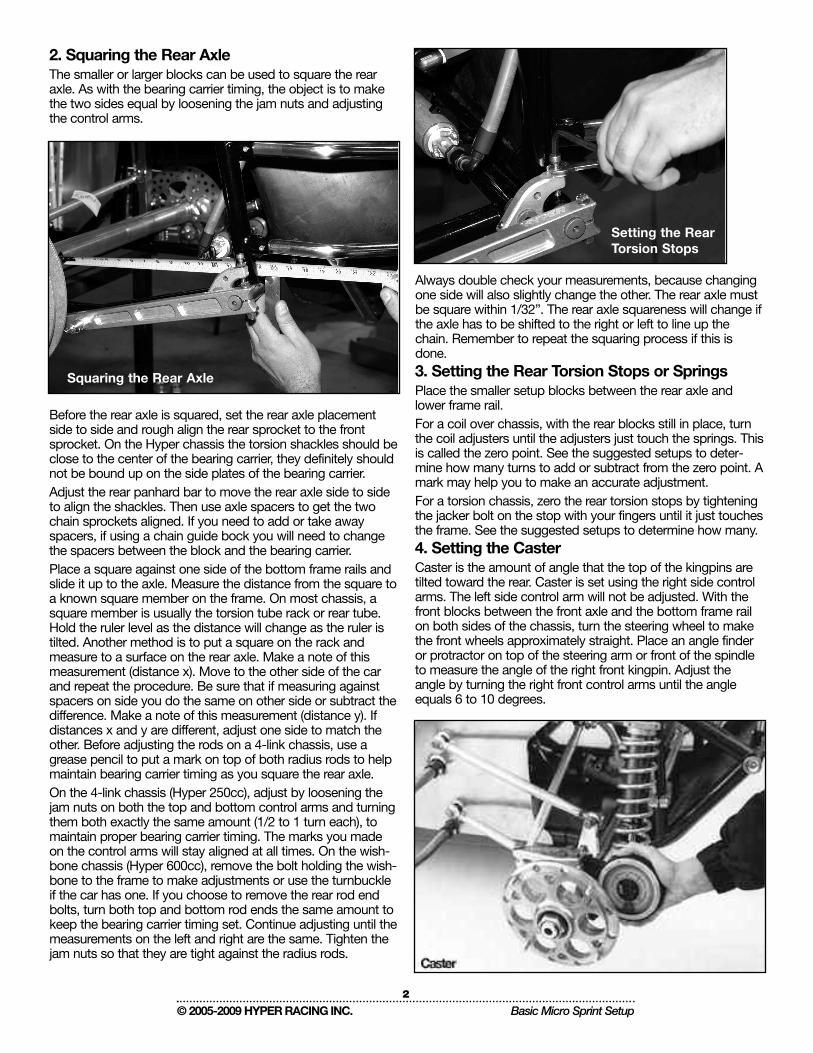
2. Squaring the Rear AxleThe smaller or larger blocks can be used to square the rearaxle. As with the bearing carrier timing, the object is to makethe two sides equal by loosening the jam nuts and adjustingthe control arms.
Before the rear axle is squared, set the rear axle placementside to side and rough align the rear sprocket to the frontsprocket. On the Hyper chassis the torsion shackles should beclose to the center of the bearing carrier, they definitely shouldnot be bound up on the side plates of the bearing carrier. Adjust the rear panhard bar to move the rear axle side to sideto align the shackles. Then use axle spacers to get the twochain sprockets aligned. If you need to add or take awayspacers, if using a chain guide bock you will need to changethe spacers between the block and the bearing carrier.Place a square against one side of the bottom frame rails andslide it up to the axle. Measure the distance from the square toa known square member on the frame. On most chassis, asquare member is usually the torsion tube rack or rear tube.Hold the ruler level as the distance will change as the ruler istilted. Another method is to put a square on the rack andmeasure to a surface on the rear axle. Make a note of thismeasurement (distance x). Move to the other side of the carand repeat the procedure. Be sure that if measuring againstspacers on side you do the same on other side or subtract thedifference. Make a note of this measurement (distance y). Ifdistances x and y are different, adjust one side to match theother. Before adjusting the rods on a 4-link chassis, use agrease pencil to put a mark on top of both radius rods to helpmaintain bearing carrier timing as you square the rear axle. On the 4-link chassis (Hyper 250cc), adjust by loosening thejam nuts on both the top and bottom control arms and turningthem both exactly the same amount (1/2 to 1 turn each), tomaintain proper bearing carrier timing. The marks you madeon the control arms will stay aligned at all times. On the wish-bone chassis (Hyper 600cc), remove the bolt holding the wish-bone to the frame to make adjustments or use the turnbuckleif the car has one. If you choose to remove the rear rod endbolts, turn both top and bottom rod ends the same amount tokeep the bearing carrier timing set. Continue adjusting until themeasurements on the left and right are the same. Tighten thejam nuts so that they are tight against the radius rods.
Always double check your measurements, because changingone side will also slightly change the other. The rear axle mustbe square within 1/32”. The rear axle squareness will change ifthe axle has to be shifted to the right or left to line up thechain. Remember to repeat the squaring process if this isdone.3. Setting the Rear Torsion Stops or SpringsPlace the smaller setup blocks between the rear axle andlower frame rail. For a coil over chassis, with the rear blocks still in place, turnthe coil adjusters until the adjusters just touch the springs. Thisis called the zero point. See the suggested setups to deter-mine how many turns to add or subtract from the zero point. Amark may help you to make an accurate adjustment. For a torsion chassis, zero the rear torsion stops by tighteningthe jacker bolt on the stop with your fingers until it just touchesthe frame. See the suggested setups to determine how many.4. Setting the CasterCaster is the amount of angle that the top of the kingpins aretilted toward the rear. Caster is set using the right side controlarms. The left side control arm will not be adjusted. With thefront blocks between the front axle and the bottom frame railon both sides of the chassis, turn the steering wheel to makethe front wheels approximately straight. Place an angle finderor protractor on top of the steering arm or front of the spindleto measure the angle of the right front kingpin. Adjust theangle by turning the right front control arms until the angleequals 6 to 10 degrees.
2
© 2005-2009 HYPER RACING INC. Basic Micro Sprint Setup
Squaring the Rear Axle
Setting the RearTorsion Stops

Less caster makes the chassis wander going down thestraight-aways, but also make it easier to turn. More castermakes the chassis hold a straighter line, but also makes itharder to turn. Less than 6 degrees of caster is not recom-mended. Drivers using direct steering may prefer 12 degreesor more of caster to simulate a direct steering setup.Once the specifications are achieved, make a reference markon the top center of each control arm to help keep the casteraccurate as you square the front axle and set the wheelbase.For both coil over and torsion, caster should be set at 8degrees. Adjustments for personal preference can be made, in2 degree increments until desired feel is achieved.5. Squaring the Front AxleBefore the front axle is squared, locate the front axle laterally(side to side). With the blocks under the axle and the fronthubs pointed straight ahead, measure directly up from thefront axle form the frame to the face of the front hub on bothsides of the car (right and left). Adjust the front panhard baruntil the offset (difference between the right and the left meas-urement) equals 3/4” more on the right than the left. Thismeans the front end is offset 3/4” to the right. This is the rightplace to start on the Hyper Chassis. We will need to check thismeasurement again when the car has tires on it and is set onthe ground, but this will get us close for squaring the front end.The front axle can be squared off of any known square framemember, on a Hyper you can use the frame member under thefront axle. Sometimes it is hard to get measurement off theframe member, but if you are comfortable doing it this way thatis fine. Set the front axle so it is parallel to the frame tube, thiswill make the front axle parallel to the ear axle.Here is another method. Start on the right side of the chassis.Using the two framing squares, slide one up against the backof the rear axle or axle spacer and the other up against thefront of the front axle. Both squares should be about the samedistance from the centerline of the chassis. Measure along theground from the face of one square to the other. Repeat theprocedure on the left side. Loosen the jam nuts and turn theupper and lower front control arms until the measurements onboth sides are equal. Be sure to maintain proper caster. Makea note of the end measurement (distance x) to use in step 6.On Hyper chassis, when you are in a hurry or at the track fol-low this procedure. With the front end up and blocks in place,take the front of the hood off, look straight down from the topof the car over the front axle and visually line up the front axle
and the front cross member directly underneath it. Adjust thecontrol arms until the two edges directly line up with eachother. This actually can be a very accurate way to square thefront axle if you have a good eye.6. Setting the WheelbaseWheelbase is the distance from the centerline of the squaredrear axle to the centerline of the squared front axle. With thefront axle square, the wheelbase can be calculated. Add thediameter of the front axle to the diameter of the rear axle orrear axle spacer if your square was against one when yousquared the front axle. Divide by 2. Subtract this from distancex determined in step 5. This number is the wheelbase. Toadjust the wheelbase, turn the upper and lower front controlarms equally on both sides. Tighten jam nuts. Generally, thewheel base can be set at 59-3/4” for 250cc and 60”-61-1/2”on the ’98-06 Hyper Chassis 600cc and 62”-63” on the 2007and up Hyper Chassis. Starting in ’07 the Hyper 600cc Chassis front axle was extend-ed forward to increase rear weight bias for more forward bite.Note: As you move the rear axle and front axle forward, rearweight bias is increased, giving more forward bite.7. LeadWhen the left front is placed further back than the right front, itis called putting lead into the chassis. Putting lead into thesetup takes weight off the left rear and puts it on the left front;this will loosen the car going in and somewhat coming off.Generally, the car can be made to handle correctly withoutresorting to adding lead to the car.8. Setting the Front Torsion Stops or SpringsFor coil over chassis, with the front blocks still in place, turnthe coil adjusters until they just touch the springs. See thesetup sheet to determine how many turns to add or subtractfrom the zero point.9. ToeToe is the term used to describe the direction the front wheelspoint relative to each other. For chassis with an axle mounted rack box or one long tie rodconnecting the left front to the right front, the toe can bemeasured either on the ground as described below or with thewheel hub method, keeping the car on stands. To measure toeusing the front wheel hubs, remove the front wheels andmeasure between the two hub faces toward the front and thetwo hub faces toward the rear.
3
© 2005-2009 HYPER RACING INC. Basic Micro Sprint Setup

For chassis with frame mounted rack boxes with two steeringrods coming off the box (one to the left front and one to theright front), you must set the toe with the car on the ground.Put a mark on the center of each front tire and spin the tires,so the mark is at the forward most part of the chassis. Takethe front and rear blocks out and set the chassis on theground. Measure the distance between the two marks. Rotatethe front tires 180 degrees and check the distance betweenthe marks.Adjust the toe by turning the steering tie rod or rods in or outaccordingly. The distance in the back should be 1/16” smallerthan the distance in the front. This is referred to 1/16” toe out.If the distance in the back were larger, it would be toe in. If youhave an accurate eye you can set the toe without measuring.Set one tire straight then adjust the steering rods so the othertire is angled out just slightly. Coil over and torsion chassisshould have 1/16” toe out. Small amounts of toe variationdoes not have any significant handling affects on the chassis.However stay away from toe in. Up to 1/2” of toe out can beused without any noticeable change. More toe adds moredrag down the straight.10. Panhard Bar HeightWith the chassis on the ground or still on blocks (does notmatter) measure from the top of the bottom frame rail to thecenterline of the rod end on the right side of the chassis.Repeat the procedure in the rear of the car and raise or lowerthe panhard bar pinch clamp until the distance equals themeasurement in the setup sheet.When sliding the panhard bar up or down, it will cause the axleto shift right or left. Make sure you readjust the axle’s offsetwhen adjusting the panhard bar height. Our adjustable rearpanhard bar assembly only moves the axle a small amount,however the rear axle’s offset should be correct when the pan-hard bar is at 6”When tightening the panhard bar pinch clamp, make sure theclamp is in line with the bar and not on an angle. Always tight-en the bolt going through the rod end first, then the smallerbolt to avoid breaking the clamp. Some chassis have a Jacob’s ladder (w-link) to locate the rearaxle. Jacob’s ladder’s are not generally adjustable. The rollcenter height of a Jacob’s ladder is determined by the inter-section of the centerlines of the top and bottom straps. TheJacob’s ladder setup has a lower initial roll center than a pan-hard bar. This is because the Jacob’s ladder setup has a rollcenter that rises as the chassis rolls and a panhard bar setuphas a roll center that lowers as the chassis rolls. The offset ofthe rear axle with a jacobs ladder can be adjusted with axlespacers or a small amount by turning the rod end in or out.11. Tire OffsetsThe right way to measure tire offsets would be to measurefrom the center of gravity to the centerline of the tires. Ofcourse, this would be way too time consuming to calculateand measure. A less accurate but much more practical way tomeasure tire offsets is from the distance of the frame to thecenterline of the tire. The problem with doing this is that mostchassis are different widths. This measurement needs tochange with the width of the frame. A wider frame requires ashorter measurement. Note to Hyper Chassis 600 owners:when viewing the offsets listed on the setup sheet, the adjust-ments for frame width has already been built into the settings.Rear Tire Offset
To set the right rear offset put the chassis on the ground withthe springs set, measure the distance from the frame upright(bump the tape measure up against the side of the framebetween the two rear bumper sockets) to the centerline of theright rear tire. Reference your setup sheet for the exact num-bers.Make adjustments from here based on track size, conditionand driver preference. If the driver weighs more than 220pounds, it will be necessary to add 1/2” to 3/4” to the setupsheet measurements. Move the right rear hub by changingspacers. Measure the distance from the frame upright on theleft side of the chassis to the center of the left rear tire. Movethe left rear hub until the tire side wall is 3/8”-1/4” away fromthe drive chain. Generally this tire is never moved. moving theleft rear tire out will slightly loosen the car when pointedstraight and tighten the car while turning left. With a wing on itcan tighten the car during the entry phase while the car isleaning left.Front Tire OffsetTo set the right front offset put the chassis on the ground andwith the front springs or bars set, turn the steering wheel tomake the front wheels point approximately straight. Make amark directly above the front axle on the top rail. Use the markon the top rail to set the right front offset. To avoid inconsisten-cies throughout the season, use paint or a scribe to make apermanent mark. Measure the distance from this point on theside of the top rail to the center line of the right front tire.Check the offset of the left front the same way as the right. Tryto achieve 3/4” offset to the right. For example, if the right frontmeasured 13-5/8” and the left front measured 13” there is 5/8”offset to the right in the front axle. Generally, more offset to theright makes the car tighter.12. StaggerStagger is the difference in circumference between the left andthe right rear tires. Circumference is the distance around theoutside of the tire.Place a stand under the rear frame rails lifting both tires off theground. Set the tire pressures. Measure the circumference ofthe left tire by placing the end of a stagger tape measure onthe tire and spinning the tire 360 degrees. Now measure the circumference of the right rear tire. Subtractthe left from the right to get the stagger.Check your setup sheet for the correct amount of stagger yourchassis requires. Make adjustments from here based on tracksize, condition and driver preference. Prestretch new tires byinflating them to 20 psi and then letting them down to racingpressures. This will help “size” the new tire before you go onthe track. Always check stagger before you race. Tires arealways stretching and shrinking. Tires can be stretched by asmuch as 1 inch by inflating them to 35 -40 psi, let them sit foras long as you can allow. Tires can be shrinked by removingthe valve stem, sitting on them to remove all the air, put thevalve stem back in and let them sit. This process of growingand shrinking tires can become an art and is necessary toachieve the right stagger to get the chassis to handel correctly.13. TiresCorrect tire compound is critical. Some are lucky enough torace at a track where all that is needed for a year of racing is aset of SD23’s or D10’s. Most racers have to put serious timeand effort into selecting the proper tire sizes and compounds.
4
© 2005-2009 HYPER RACING INC. Basic Micro Sprint Setup

There is no formula to picking the right compound. Often itboils down to personal experience, and trial and error. Basethe decision on reading of the track condition and driving style.Consider the front tires in the equation. If the track is especiallyhard, and harder tires are needed in the rear, then harder tireswill be needed on the right front as well. Generally use onestep softer compound tire on the right front than the right rear.
Remember, every track is different. Learn to read your track bylooking at it up close, checking the moisture and hardness lev-els. Rate the track from hard and dry to soft and wet. Watchfor abrasiveness on the track as a sure signal of a hard track.Look at tire wear of cars coming off the track.Don’t assume what worked for the heat races will be the bestchoice for the feature. After the race, feel the right rear andexamine it for feathering. If feathers are longer than 1/8” thetire was too soft. Feathers on tires are bad because the carrides on the feathers eliminating all the other friction generatingsurface area.A softer tire will generate more traction but will feather edgesmore quickly and can over heat more quickly. A hard tire willprovide less traction unless the track is abrasive or hard.Grinding and groving tires is important for those of us whocan not afford to put new tires on for every race. Grinding tiresis really important to remove the lip that forms on tires on thetrailing edge, removes feathers, and to remove any glaze orhardness that forms on the outer most surface of the tires. Theheat generated during the grinding process will also pull up theoil in the tire to the outer surface making it have more traction.
Grinding tires is more effective on harder tires than softer tires.Groving tires is important if you are racing on a track where thetire is working into the surface (clay). It is the sharp edges thatprovide the traction on these surfaces. More sharp edges =more traction, think of a paddle in the water. As the track hard-ens and becomes abrasive, the edges of the tire become lessimportant. On a hard track it is actually better to have lessedges and more surface area. Radial grooves give side bite,grooves across the tire give forward bite.Sipes are slits cut into the tire with a razor type blade. Thistype of tire preparation provides small, short lived edges. Theycan also help the tire heat up quicker by generating frictionbetween the faces of the sipe, then as the tire heats up thesipes separate and allow the tire to run cooler. Spies are usefulwhen running on a hard track and a hard tire is being used, thesipes will help the tire ‘come in’ quicker.14. Shocks and SpringsWhen combined with the other facets of chassis tuning,changing shock rates can assist in reaching a new level inhandling perfection. A driver who is consistent and sensitive tochanges can achieve fine tuning right away with shocks. Newdrivers should spend a test day experimenting with shockrates to get a good feel for how they affect the chassis. Eitherway, a shock dyno is a partner in shock tuning.“Dampening” or “damping” is a term used in shock technolo-gy meaning, to check, depress, reduce or lessen.” Theseterms can be used interchangeably. Torsion Bars achieve sus-pension properties through twisting of one end of the bar whilethe other end is held firm. Torsion Bars are simply another formof springs and will be referred to as “springs”. “Compression”is when the shock gets shorter; “rebound” is when the shockgets longer. For example, when the front bumper is steppedon, the shocks are compressed, and when the bumper isreleased, the shocks rebound.
The suspension system controls movements of the chassiswhen the wheels hit bumps or during natural weight transferwhen the chassis is accelerating, decelerating, or negotiating aturn. Shocks and springs work together to control how thechassis moves. The springs absorb the bumps and controlbody roll. Shocks control the speed of extension and com-pression of the spring during weight transfer. A stiffer shockwill slow down a spring’s action; a softer shock will allow thespring to act faster.The primary purpose of the shocks and springs is to make thechassis stable and predictable while driving over bumps orruts. If the shock/spring combination is too stiff, the tire can bepulled off the track surface for a period of time, eliminating thattire’s traction ability. If the shock/spring combination is too soft,
5
© 2005-2009 HYPER RACING INC. Basic Micro Sprint Setup
tire compoundsAmerican Racer Hoosier
Soft SD23 D10SD28 **SD33 D12SD35 **SD38 D15SD44 D20SD48 D25MD50 D35MD57 **
Hard HD65 **** no equivalent

the chassis can bottom out on the track, again hindering trac-tion ability. This loss of traction in both scenarios can causethe chassis to skate and make the chassis unpredictable anddifficult to drive. Also, it can make it impossible for the driver totell if the chassis is tight or loose.The secondary purpose of shocks and springs is to controlwhere the weight transfers, for a detailed explanation of this,see the document called “My Big T.O.E. on Dirt” available onthe hyper owners section of the website.A shock dampens the spring by displacing hydraulic fluid fromone end of the shock to the other through a small hole orvalve. On rebuildable shocks, valving can be changed to makethe shock stiffer or softer. The valves controlling compressionor rebound can be changed independently. This is called asplit valve shock.Check your setup sheet for recommended starting points forshocks torsion bar sizes and spring rates. Realize that if youdo not have a Hyper chassis your chassis may have differentarm lengths than what Hypers use. Arm lengths have a hugeaffect on spring rate. Use the torsion bar spring rate formulafound at hyperracing.com to find the size bars needed toachieve the same rates as suggested.
15. WingThe top wing has a very large effect on the chassis. Start withthe wing mounted in the hole closest to the front. Slide thewing to the front most position in the sliders. Wings weighingmore than 18 pounds are not recommended because they willchange the center of gravity and make the chassis very incon-sistent. Lay a protractor on the front part of the center sectionand slide the rear wing upright until the protractor reads 12-28degrees.16. Tire PressuresAs a general rule, only vary tire pressures (2-8 pounds) withtrack conditions. More pressure will be used on a tacky track.Tire pressures control the spring rate of a tire. The tire springrates work exactly like the spring rates on the chassis. Moretire pressure or stiffer spring rates on the right side of the chas-sis will make it looser. More tire pressure or stiffer spring rateson the left side of the chassis will make it tighter. A commonmisconception is that taking tire pressure out of the left rearwill tighten the chassis, when actually the opposite is true. Notonly does more left rear tire pressure make the left rear springrate stiffer but it also adds static weight to the left rear becauseit raises the car on that corner and takes away staggerbecause adding tire pressure will always make the tire larger incircumference.17. Weight Distribution and Scaling the ChassisScaling the chassis is optional but can be useful. Always scalethe chassis with the driver sitting in it. Use the same spot onthe floor each time you scale the chassis for consistency. On atorsion car, unhook the shocks to eliminate any residual forces.Also, keep the same amount of fuel in the tank and set the tirepressures to race ready levels.Digital scales are the most accurate. Shipping scales that canbe purchased at an office supply store are reasonably accu-rate. Bathroom scales are generally inconsistent but with apiece of wood on top to help distribute the weight across thescale, they can be an inexpensive way to start.
Rear Weight Bias or PercentageCalculate the rear weight bias by adding the rear weight (LRand RR) of the chassis and dividing it by the total weight of thechassis (LF + RF + LR + RR). The more rear weight bias, thetighter the chassis will be going in and coming out of a turn.For the 4-link and wishbone chassis, 62%-65% works best.Heavier drivers will add more. If upon calculating your weightbias, you were not in the target zone, you can make adjust-ments to change it accordingly. Move the seat forward willreduce the rear weight bias, to the rear will increase it. Movingthe rear axle back, by making the rear control arms longer andthe front control arms shorter will reduce rear weight bias.Conversely, moving the rear axle forward will increase it.Right Rear Weight vs. Left Rear WeightTrack conditions, size and shape as well as wing size andshape will have an affect on what static weights you will wanton the left rear. The bigger and higher the wing the more rightrear weight you will need to get the best balance. Small trackslike more left rear weight, big track more right rear weight. Fora detailed explanation of this, see the document called “MyBig T.O.E. on Dirt” available on the Hyper owners section ofthe website.CrossbiteCalculate the crossbite by adding the RF and LR and dividingby the total weight of the chassis. Look for about 42%-49%crossbite. Adding turns to the right front-left rear, and takingturns out of the left front-right rear is a how to increase cross-bite. Crossbite decreases when the right rear is moved in totighten the chassis. Therefore, this number cannot be lookedat without taking all other factors into consideration. With theheavy tie down shocks we now run and the big wing side pan-els, the left rear is usually overloaded, decreasing overall trac-tion. Generally on the Hyper Chassis with the recommendedshocks, try to hit 0-15 pounds heavier on the right rear thanthe left rear.For a detailed explanation of this, see the document called“My Big T.O.E. on Dirt” available on the Hyper owners sec-tion of the website.Left Side Weight Bias or PercentageAdd the LF and LR and divide by the total weight of the chas-sis to calculate the left side weight bias. This is affected mostlyby moving the right side wheels in or out and by moving theleft side tires in or out. Scaling as a Diagnostic ToolScaling the chassis can be useful in detecting binds in thechassis caused by bent or bad rod ends, bent shocks, bentaxles, bent frames, or axles out of square. First scale the newchassis after the setup procedure is complete and record allthe numbers and the exact setup you used. Then, after eachrace, put the chassis back to that setup and rescale the chas-sis and compare the numbers. If they are more than 4 poundsoff (per corner), then something has changed.
SUGGESTED ADJUSTMENTSReference the setup sheet for suggested adjustments.
6
© 2005-2009 HYPER RACING INC. Basic Micro Sprint Setup