Embed Size (px)
Citation preview

J. Aerosol Sci. Vol. 31, No. 1, pp. 121}136, 2000( 1999 Elsevier Science Ltd. All rights reserved
Printed in Great Britain0021-8502/99/$ - see front matterPII: S0021-8502(99)00534-0
PREPARATION OF ZnS NANOPARTICLESBY ELECTROSPRAY PYROLYSIS
I. Wuled Lenggoro,* Kikuo Okuyama,*s Juan FernaH ndez de la Morat and Noboru Tohge A
*Department of Chemical Engineering, Hiroshima University, Higashi-Hiroshima 739-8527, JapantDepartment of Mechanical Engineering, Yale University, New Haven, CT 06520-2159, U.S.A.ADepartment of Metallurgical Engineering, Kinki University, Higashi-Osaka 577-0818, Japan
(First received 6 October 1997; and in ,nal form 23 June 1998)
Abstract*Zinc sul"de particles 20}40 nm in diameter were prepared by electrically driven spraypyrolysis. Solutions of ethyl alcohol with zinc nitrate (Zn(NO
3)2) and thiourea (SC(NH
2)2) at
concentrations from 0.0025 to 0.2 mol l~1 and electrical conductivities between 10~4 and10~1 Sm~1 were electrosprayed from steady cone-jets at #ow rates from 0.05 to 0.16 ml h~1, withpositive and negative polarity. The initially highly charged drops formed were neutralized by bipolarions from a radioactive source to increase the overall transmission e$ciency through a reactorfurnace. This process was made particularly e!ective by the innovation of placing the ion sourcedirectly within the electrospray chamber. The diameters of the "nal ZnS particles were measuredon-line by a di!erential mobility analyzer and a condensation nucleus counter. In spite of ambi-guities in the #ow rate of liquid through the cone}jet (associated to solvent evaporation from themeniscus), these diameters agree approximately with values expected from available scaling laws.Transmission electron micrographs also con"rmed these results. Electrospray pyrolysis is hence ableto generate non-agglomerated and spherical ZnS nanoparticles with geometrical standard deviationp'
of about 1.3. ( 1999 Elsevier Science Ltd. All rights reserved
1 . INTRODUCTION
Spray-pyrolysis is a droplet-to-particle conversion process, whose low cost and simplicityhas stimulated its frequent use in the preparation of a variety of functional material particlesand thin "lms (Gurav et al., 1993; Messing et al., 1993). In this technique, aqueous solutionsof metal salts are "rst atomized into droplets, which are subsequently pyrolyzed to becomesolid particles. The average diameter of the "nal solid particles can be roughly determinedfrom the droplet size and the solute concentration of the solution sprayed. The atomizersmost commonly used to generate such droplets (twin-#uid or ultrasonic nebulizers) tend toproduce average diameters in the range of several microns. For a droplet to dry froma typical initial diameter of 5 km into a particle with a diameter of 0.1 km, the initial volumefraction of dissolved involatile solute must be less than 0.0008%. In practice, these lowsolution concentrations lead to a low particle generation rate and make it di$cult tomaintain a high purity of the "nal particle product. In spite of these di$culties, Okuyamaet al. (1997) have produced size-controlled zinc sul"de (ZnS) and cadmium sul"de (CdS)particles by changing the solution concentrations in ultrasonic spray pyrolysis. Theirultrasonic nebulizer generated droplets 4.56 km in average diameter, from which ZnS andCdS particles 0.2}1.5 km were prepared by varying the solution concentrations from 0.001to 0.3 mol l~1. However, as noted by Rulison and Flagan (1994a), the preparation ofparticles below 0.1 km via traditional spray pyrolysis methods remains problematic.
The electrospray technique is one of the few known schemes capable of atomizing a liquidinto ultra"ne droplets. In this method, the meniscus of a conducting solution supported atthe end of a capillary tube becomes conical when charged to a high voltage (several KV)with respect to a counter electrode. Droplets are then formed by the continuous breakup ofa steady jet naturally forming at the apex of this cone, generally called a &&Taylor cone''(Taylor, 1964). The full structure is often referred to as a cone}jet (Cloupeau and
sAuthor to whom correspondence should be addressed.
121

Prunet-Foch, 1994). A variety of experimental studies have shown that the diameter of suchjets and drops may be controlled from nanometers in liquid metals (Benassayag et al., 1995)up to hundreds of micrometers in dielectric liquids such as heptane (Jones and Thong,1971), mostly through the electrical conductivity of the liquid or the #ow rate (e.g., Smith,1986; Rossel-Llompart and FernaH ndez de la Mora, 1994; Ganan-Calvo et al., 1997).Recently, Chen et al. (1995) have reported the production of approximately monodispersedry residues in the range of 40 nm to 1.8 km using aqueous sucrose solutions with electricalconductivities ranging from 1.56]10~3 to 8]10~1 S m~1. This work has been extended byChen and Pui (1997) to a variety of other liquids with dielectric constants from 12.5 to 182.
The droplets generated in an electrospray are always highly charged. Their associatedlarge electrical mobility hence leads to considerable losses by deposition onto the walls,which decreases drastically the particle overall throughput e$ciency. This di$culty iscompounded by the occurrence of Rayleigh disintegration during the drying process, whichbroadens the initial narrow size distribution. Fortunately, these two problems may beeliminated by neutralizing the drops immediately after production. Electrical neutraliza-tions of electrosprayed droplets through a source of ions of the opposite polarity has beenreported among others by Noakes et al. (1989), Meester et al. (1993) and Chen and Gomez(1996). Cloupeau (1994) reviewed four possible neutralization methods; a unipolar-typecorona discharge, an electrospray of a volatile liquid, thermoelectric emission, and a #ame.Recently, the application of a radioactive bipolar ion source as the neutralizer for electro-spray drops was reported by Zarrin et al. (1991a, b), Lewis et al. (1994), Chen et al. (1995)and Kaufman et al. (1996) with two Po-210 sources (370 MBq) and by Rulison and Flagan(1994b) with one Po-210 source (185 MBq).
Following the pioneering work of Fenn and his colleagues, the most common use ofelectrosprays has been as ion sources for mass spectrometry of large and labile biomolecules(Fenn et al., 1989). However, there have been a wide variety of other applications ofelectrosprays in particle production (e.g., Bollini et al., 1975; Mahoney et al., 1987; Leviet al., 1988; Salata et al., 1994; Danek et al., 1994, 1996; Jensen and Sorensen, 1996; Renekerand Chun, 1996; Hull et al., 1997; Sobota and Sorensen, 1997; Teng et al., 1997), includingspray pyrolysis (Slamovich and Lange, 1990; Park and Burlitch, 1992; Rulison and Flagan,1994a). A preliminary study of Okuyama et al. (1996) has also reported the production ofZnS and CdS particles below 0.1 km in diameter by electrospray pyrolysis. However, innone of these earlier studies on electrospray pyrolysis was the spray functioning mode fullydetermined as a function of spray liquid #ow rate or applied voltage, nor were the precisein#uences of the concentration or the physical properties of the solutions on the size ofgenerated solid particles entirely clari"ed.
The present work constitutes the "rst attempt at a systematic control of all the keyvariables governing electrospray pyrolysis, including liquid #ow rate, applied voltage andsolute concentration, while operating in the steady cone}jet mode (Cloupeau and Prunet-Foch, 1989, 1990). The particles generated are measured on-line by a di!erential mobilityanalyzer and a condensation nucleus counter system, as well as o!-line by thermophoreticsampling followed by transmission electron micrographic analysis. In spite of ambiguitiesregarding the actual liquid #ow carried by the jet (due to solvent evaporation from themeniscus), the particle sizes determined after drying compare favorably with those expectedfrom available scaling laws for the original drops.
2 . EXPERIMENTAL APPARATUS AND PROCEDURE
Figure 1 shows the set-up used to generate ZnS particles and investigate the e!ect ofexperimental conditions on their physical characteristics. It comprises (i) an electrospraysource, (ii) a reaction furnace, and (iii) a size-analysis section, including a di!erentialmobility analyzer (DMA, TSI model 3071), a condensation nucleus counter (CNC, TSImodel 3020), and a home-made thermophoretic sampler.
Earlier studies on the preparation of ZnS and CdS particles using ultrasonic spraypyrolysis have used pure water as the solvent. However, because of its large surface tension,
122 I. W. Lenggoro et al.

Fig. 1. Schematic of the overall experimental apparatus of electrospray pyrolysis.
establishment of a Taylor cone of water requires high applied voltages that leads toelectrical breakdown of the surrounding air. In the positive mode, this di$culty may beovercome by using a sheath gas with relatively high electrical breakdown threshold, such asCO
2or SF
6(Zeleny, 1915; Smith, 1986). However, because CO
2would lead to oxidation of
the Zn in the "nal product, we have used nitrogen as a sheath gas, at a constant #ow rate of1.0 lmin~1. Zinc nitrate [Zn(NO
3)2] and thiourea [SC(NH
2)2] were used as the sources
of Zn and S, respectively. Ethanol was chosen as the solvent because of its good solubility inthese two solutes, as well as for its low surface tension, which makes it possible to producestable Taylor cones of positive and negative polarity in nitrogen.
As described in equation (1) (Tohge and Minami, 1992), zinc nitrate and thiourea forma complex in solution. The droplets containing the complex are then pyrolyzed to synthesizedirectly ZnS particles at a furnace temperature around 6003C which is necessary to drive thereaction (Okuyama et al., 1997).
Zn(NO3)2#(NH
2)2SCNZn(SC(NH
2)2)2(NO
3)2NZnS. (1)
The molar ratio of Zn : S was kept constant at 1 : 2, since pure ZnS phase could not beobtained at 1 : 1 (Zn : S). This behavior has been observed in previous work by Tohge andhis colleagues on the formation of ZnS particles via spray pyrolysis (Tohge et al., 1995) whovaried the ratio of Zn : S from 1 : 1 to 1 : 3. The crystalline phase found was hexagonal in therange of temperatures from 600 to 8003C, while higher temperature led to the appearance ofZnO phase in addition to ZnS. For reasons which remain unclear, the best and purest ZnSphase was obtained at Zn : S"1 : 2. In another study on the preparation of CuS particlesusing ultrasonic spray pyrolysis, Lenggoro et al. (1998) found that they could not produceCuS with Cu : S"1 : 1, the best CuS phase being formed again for Cu : S"1 : 2. Hence, itappears that the decomposition of the dissolved complex involves the loss of sulfur, perhapsvia H
2S.
Table 1 shows the physical properties of the solvent and solutions used. Four di!erentsolution concentrations C
4were electrosprayed. Increasing C
4by two decades did not
change substantially the density o and viscosity k of the liquid, but increased its electricalconductivity K by about 35 times (compare the highest with the lowest C
4), and by 1600
times with respect to the unseeded solvent. The most important physical property of thesolution controlling both the stability of the electrospray (Cloupeau and Prunet-Foch,1989; Tang and Gomez, 1996) and the droplet size is known to be the liquid electrical
Zinc sul"de particles by electrospray pyrolysis 123

Table 1. Physical properties of the pure solvent and the solutions used
C4(mol l~1) o (kgm~3) k (mPa s) K (S m~1)
0 788.9 1.207 1.20]10~40.0025 789.6 1.220 5.62]10~30.01 791.5 1.243 2.01]10~20.05 801.4 1.365 6.53]10~20.20 838.8 1.822 1.92]10~1
conductivity K. Thus, this study focused on this parameter. Notably, the value K around0.2 S m~1 is fairly large in relation to typical literature values. The electrical conductivity ofthe solutions was measured by a conductivity meter (Toko Chemical Inc., TX-90) at 253Cand the liquid density and viscosity by an Ostwald-type pycnometer and a viscometer,respectively.
The liquid was sprayed inside a six ways cross stainless-steel chamber (Fig. 1). Two of theopposing sides were used for supplying the spraying liquid and sampling the generatedaerosols. Positive and negative DC high voltage sources (Matsusada Co. Ltd., HER-10R3)were connected to the stainless-steel capillaries. Two such capillaries were used, havinginner/outer diameters of 0.90/1.20 and 0.40/0.88 mm. These will be referred to as the &&large''and the &&small'' capillary, respectively. Each capillary tip was tapered conically down tonearly zero thickness. The liquid was supplied to the capillary either through a programm-able syringe pump (Harvard Apparatus, Model 55) or, optionally, by introducing com-pressed nitrogen above the sample liquid inside a vertical syringe. In the latter method, the#ow rate of solution was calibrated by measuring the moving velocity of a gas bubbleinjected into the solution line through a burette.
In order to reduce the evaporation of solvent at the cone, an attempt was made tosaturate the nitrogen gas with ethanol vapor by passing it through an ethanol reservoir.A precipitate, however, still appeared at the capillary tip after running times of tens ofminutes at solution concentrations ranging from 0.05 to 0.2 mol l~1.
A stainless-steel tube having an inner diameter of 5 mm was used to sample the aerosol.Its distance to the spraying needle was adjustable, but was kept at 40 mm for most runs.This sampling tube was grounded through an electrometer (Keithley, model 485) formeasuring the electric current brought by the droplets that were deposited onto it and thechamber wall. This allowed monitoring the stability of the electrospray. The noise level ofthe electrometer remained in the range of 1.0 nA. The spray capillary electrode andsampling tube were set horizontally to facilitate the connection of the spray chamber toa furnace or a DMA-CNC system. Another pair of opposite sides of the chamber arewindows for monitoring the meniscus shape at the capillary tip, through a 30] microscopeset at one side and a continuous light source at the other.
Because of its simplicity and stability, an a-ray radioactive source (241Am; 2.22 MBq) wasused to produce bipolar ions for drop neutralization. It was placed several millimetersin front of the conical tip in the axial direction, and about 45 mm in the radial direction,above the range of the a-rays from 241Am (40 mm). To test the e!ectiveness of theneutralizer, the number concentration of the generated particles was measured right at theoutlet of the spray chamber. It increased from a value of the order of 102 or 103 withoutneutralization up to 106 particles cm~3 with neutralization. This favorable tendency wasalso observed when the 241Am was located at the outlet of the spray chamber, as describedin Fig. 1. Since neutralization of the particles could greatly improve their throughpute$ciency, the 241Am source was installed in all subsequent experiments.
The neutralization scheme used in this work di!ers from all other approaches which weare aware of in that the ion source is not electrically shielded from the high "elds created bythe spraying needle. Earlier work on the combustion of electrosprayed drops of fuel (Thongand Weinberg, 1971; see also Chen and Gomez, 1996) isolated #ame chemi-ions from thespraying needle by means of a grounded metal gauge. Similarly, Kaufman and colleagues
124 I. W. Lenggoro et al.

and Rulison and Flagan have introduced their radioactive source in a chamber downstreamfrom the electrospray chamber. Presumably, these precautions were inspired by the well-known fact that the physical situation is quite di!erent when the gas surrounding themeniscus ceases to be a perfect insulator. For instance, dating back to Zeleny's earlyobservations, there are numerous reports showing that discharges originating at the tip ofthe cone do modify the stability range of the cone}jet, the current-#ow rate relation, andmost likely also the diameter of the emitted drops. Even in the presence of a peculiarly weakand visually imperceptible discharge sometimes arising for water electrosprays in air changeto CO
2, Tang and Gomez (1995) have reported that the corresponding stability island is
extended considerably towards smaller #ow rates, while the drop diameter correspondingto a given #ow rate is smaller than in the pure cone}jet mode. In spite of these precedents,we "nd that the current versus voltage relations are not shifted in any substantial way by thepresence or absence of the radioactive source, provided that it is kept more than 40 mmaway from the needle. Hence, it is clear that electrical isolation of the cone}jet from the ionsource is not always essential, at least when the space charge in the spray region consumesa su$cient fraction of the ions to avoid an excessive disturbance of the usual dynamics ofthe Taylor cone. It is worth noticing that, although the neutralization scheme of Rulisonand Flagan (1994b) was inspired in TSI's approach (Zarrin et al., 1991), the relatively largeaperture they introduced between the electrospray and the neutralizer chamber allowedpartial penetration of the "eld from the needle into the chamber containing bipolar ions,and some of these were clearly drawn into the region of the needle, as indicated by theauthors remark &&With no spray established, gas ions generated some current when anelectric "eld was applied. On the other hand, with a spray established, the current was thesame with and without the discharger. This indicates that the ions were probably intercep-ted by liquid droplets''. Note, however, that the current was measured with a modestresolution of only 10 nA.
Besides its greater simplicity, two advantages of introducing the neutralizer directly intothe electrospray chamber are that : (i) drop losses associated to the passage from theelectrospray region to the neutralization region are avoided, and (ii) neutralization is moreimmediate, with a consequently reduced danger of Coulombic explosions.
The droplets generated were introduced from the spray chamber into a reaction furnaceusing nitrogen carrier gas. In order to reduce the loss of particles, a relatively short tubularfurnace was used. It comprised a quartz glass tube of 20 mm inner diameter and 200 mmlong, with two independently controlled heating zones 10 cm long. The residence timeinside the furnace was estimated to be 1.5 s for 1.0 l min~1 of carrier gas #ow. All experi-ments were made at atmospheric pressure and with a furnace temperature of 6003C.
Following the heated furnace, the resulting dry ZnS particles were sized with a DMA-CNC system, similarly as in earlier studies. The sheath air in the DMA is set to 10 lmin~1
and the #ow ratio of aerosol to sheath air is kept at 0.1. Alternatively, a thermophoreticsampler with a 150-mesh brass grid was placed at the outlet of the furnace. These sampleswere examined and photographed by transmission electron microscopy (TEM) to verifyand support the data obtained from the DMA-CNC system.
3 . EXPERIMENTAL RESULTS
3.1. Determination of the stability domain of the cone}jet
Di!erent spray modes may lead to quite di!erent drop size distributions for a givensolution (e.g. Cloupeau and Prunet-Foch, 1989). Hence, before measuring the particle sizedistributions, one must distinguish and control the regime at which the liquid cone and thespray operate. Figure 2 shows typical curves of the electric current versus the appliedvoltage of (a) ethanol and (b) 0.0025 mol l~1 solution, performed without the 241Amneutralizer using the apparatus shown in Fig. 1. Flow rates fed to the small capillary bya syringe pump were kept constant at (a) 0.20 ml h~1 and (b) 0.08 ml h~1. First, the appliedpositive voltage was increased gradually, and then reduced after the liquid meniscus at the
Zinc sul"de particles by electrospray pyrolysis 125
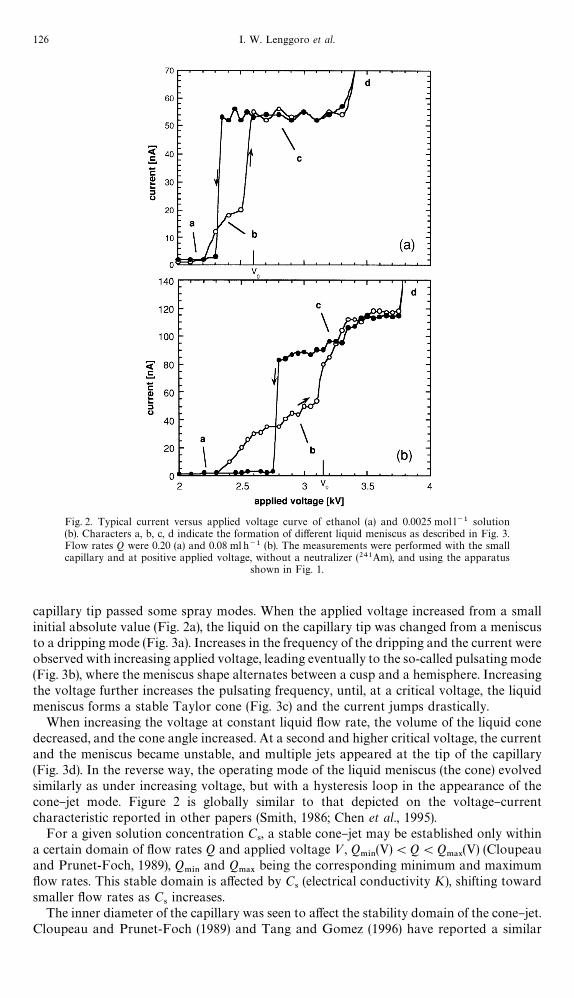
Fig. 2. Typical current versus applied voltage curve of ethanol (a) and 0.0025 mol l~1 solution(b). Characters a, b, c, d indicate the formation of di!erent liquid meniscus as described in Fig. 3.Flow rates Q were 0.20 (a) and 0.08 ml h~1 (b). The measurements were performed with the smallcapillary and at positive applied voltage, without a neutralizer (241Am), and using the apparatus
shown in Fig. 1.
capillary tip passed some spray modes. When the applied voltage increased from a smallinitial absolute value (Fig. 2a), the liquid on the capillary tip was changed from a meniscusto a dripping mode (Fig. 3a). Increases in the frequency of the dripping and the current wereobserved with increasing applied voltage, leading eventually to the so-called pulsating mode(Fig. 3b), where the meniscus shape alternates between a cusp and a hemisphere. Increasingthe voltage further increases the pulsating frequency, until, at a critical voltage, the liquidmeniscus forms a stable Taylor cone (Fig. 3c) and the current jumps drastically.
When increasing the voltage at constant liquid #ow rate, the volume of the liquid conedecreased, and the cone angle increased. At a second and higher critical voltage, the currentand the meniscus became unstable, and multiple jets appeared at the tip of the capillary(Fig. 3d). In the reverse way, the operating mode of the liquid meniscus (the cone) evolvedsimilarly as under increasing voltage, but with a hysteresis loop in the appearance of thecone}jet mode. Figure 2 is globally similar to that depicted on the voltage}currentcharacteristic reported in other papers (Smith, 1986; Chen et al., 1995).
For a given solution concentration C4, a stable cone}jet may be established only within
a certain domain of #ow rates Q and applied voltage <, Q.*/
(V)(Q(Q.!9
(V) (Cloupeauand Prunet-Foch, 1989), Q
.*/and Q
.!9being the corresponding minimum and maximum
#ow rates. This stable domain is a!ected by C4(electrical conductivity K), shifting toward
smaller #ow rates as C4increases.
The inner diameter of the capillary was seen to a!ect the stability domain of the cone}jet.Cloupeau and Prunet-Foch (1989) and Tang and Gomez (1996) have reported a similar
126 I. W. Lenggoro et al.

Fig. 3. Photographs of the various meniscus shapes: (a) dripping mode, (b) pulsating mode, (c) stablecone}jet mode, and (d) multi-jet mode.
behavior for the di!erent case of liquids with low dielectric constant and low conductivity,with Q
.*/increasing as the capillary diameter increases. However, most other studies with
conducting liquids observed no e!ect of either the electrostatic variables or the capillarydiameter on Q
.*/(FernaH ndez de la Mora, 1992; FernaH ndez de la Mora and Loscertales,
1994; Rossel-Llompart and FernaH ndez de la Mora, 1994; Chen et al., 1996, 1997; Ganan-Calvo et al., 1997). The unusual trend found here is surely due to the fact that theevaporation #ux Q
%7!1of liquid from the meniscus is not negligible at the scale of the
relatively small #ow rates involved in this work, particularly at the higher electricalconductivities. If we de"ne Q
+%5as the liquid #ow rate Q pushed through the jet, and Q
&%%$as
that fed to the capillary, mass conservation implies that Q+%5"Q
&%%$!Q
%7!1. For given Q
+%5,
Q%7!1
is larger for the larger capillary, hence requiring that Q&%%$
be also larger than for thesmall capillary. Consequently, the use of a large capillary causes a narrowing of the cone}jetdomain of the electrospray. This observation is in consonance with the fact that the spraycurrent is independent of the applied voltage in Fig. 2a (low conductivity), but increaseswith it in Fig. 2b (high conductivity). In the "rst case, Q
%7!1;Q
&%%$, and there is no
dependence on electrostatic variables, as discussed in earlier work. The behavior in Fig. 2bmay be explained by the reduction of the cone angle (hence the area available to evapor-ation) with cone voltage, which then gives rise to an increase in Q
+%5which itself increases the
spray current.The sign of the applied voltage was also found to a!ect the stable cone}jet domain,
negative voltages requiring higher #ow rates (both Q.*/
and Q.!9
) than positive voltages.
Zinc sul"de particles by electrospray pyrolysis 127

However, this e!ect is most likely due to the appearance of corona discharges, favored in thenegative mode (Zeleny, 1915), and frequently observed visually in this work.
At the higher C4, the "rst mode to appear is occasionally the cone}jet mode (Cloupeau
and Prunet-Foch, 1994). As mentioned before, at C4"0.05 and particularly at 0.2 mol l~1,
the salt precipitated on the capillary tip after several tens of minutes of operation, even whenthe carrier gas was saturated with ethanol. This made the sampling of the particles di$cult,since more than 1 h is needed to obtain a suitable quantity of sample.
Due to the volatility problem and other di!erences (electrode geometry, liquid propertiessuch as electrical conductivity and vapor pressure), the range of liquid #ow rates where wecould form a stable spray was narrower in this work than in earlier studies (Rossel-Llompart and FernaH ndez de la Mora, 1994; Cloupeau and Prunet-Foch, 1989; Chen et al.,1995). For instance, in the case of C
4"0.0025 mol l~1 spraying at small capillary and
positive voltage, Q.*/
was 0.09 and Q.!9
was about 0.20 ml h~1. The narrowest range, i.e.the smallest ratio Q
.!9/Q
.*/was found at C
4"0.2 mol l~1, with Q
.*/"0.05 ml h~1 and
Q.!9
"0.08 ml h~1. No stable spray could be formed at any voltage in our system below0.05 ml h~1.
Since it has been previously established that lower #ow rates of spray liquids generatesmaller and more narrowly dispersed electrospray droplets (Rossel-Llompart and FernaH n-dez de la Mora, 1994), an attempt was made in this study to maintain Q near the minimumvalue Q
.*/. At a certain applied voltage<(Q), we "nd that the cone is most easily controlled
near Q.*/
, where the #uctuation of the current is also smallest.
3.2. Size distribution of ZnS particles
Particle size distributions were measured using a DMA}CNC system. In each case,the furnace temperature was kept at 6003C and the liquid #ow rate Q was near or at theminimum value Q
.*/. Figure 4 shows the in#uence of the applied (negative) voltage and
the electrospray mode on the particle size distributions for C4"0.01 mol l~1 and Q"
0.10 ml h~1. The particle size distribution function expressed by f (ln d1) is
f (ln d1)"(*n/*ln (d
1))/N, (2)
and the data were relaxed following Adachi et al. (1990). *n is the number concentration inthe size range *d
1, and N is the total particle number concentration. All the "gures show
a geometrical standard deviation p'
of about 1.3. Figure 4a corresponds to the pulsatingmode, with an associated volume mean diameter d
1of 32.6 nm. The particle size distribu-
tions for the cone}jet modes are shown in Fig. 4b (3.15 and 3.5 kV). This corresponds to"ner particles than in the pulsating mode, where the oscillation between two di!erentmeniscus shapes and the related formation of a transient jet introduces di!erent and largerbreakup volumes (Cloupeau and Prunet-Foch, 1989, 1990; Chen et al., 1995).
Figure 4b shows aerosol size distributions for the cone}jet mode, indicating that thevolume mean diameter increases slightly with increasing applied voltage. A similar tendencywas reported by Rulison and Flagan (1994b). Tang and Gomez (1996) "nd an analogoustrend in electrosprays of heptane, although the behavior of such low conductivity liquids isknown to be quite di!erent from that of our own solvent. On the other hand, Rossel-Llompart and FernaH ndez de la Mora (1994) as well as Chen et al. (1995, 1997) "nd thatdroplet size is nearly independent of applied voltage for liquids of high electrical conductiv-ity. Again, the discrepancy with our results and with those of Rulison and Flagan (1994b;who used a capillary diameter of 1.65 mm for solution conductivities between 0.007 and0.356 S m~1) is probably due to solvent evaporation from the meniscus, since a highervoltage reduces the cone volume and hence the evaporation loss. An indication of theevaporation problem experienced by Rulison and Flagan (1994b) is given by their anomal-ously high liquid #ow rates. On page 138 they note a disagreement by factors ranging from30 and 80 betwen their jet radius a and the formula a&[oQ2/(2cn2)]1@3 proposed byFernandez de la Mora et al. Indeed, this relation was later shown to be approximately validonly at relatively large #ow rates, but not near the minimum value (Rossel-Llompart and
128 I. W. Lenggoro et al.

Fig. 4. Measured particle size distributions at (a) pulsating mode (2.90 kV) and (b) stable cone}jetmode: 3.15 and 3.50 kV, for a solution concentration C
4"0.01 mol l~1 and a #ow rate of
0.06 ml h~1.
FernaH ndez de la Mora, 1994). However, the error involved is proportional to the factorg2@3 introduced later in equation (6), which is always of order unity near the minimum #owrate. The disagreement factors of 30}80 reported are hence more likely due to substantialerrors in Q associated to liquid evaporation. This problem is clearly present also in Fig. 5 ofRulison and Flagan (1994a), which plots the liquid #ow rate versus electrical conductivityunder "xed conditions of the jet geometry. Although the scaling laws now "rmly established(see Section 4.2) require that the product KQ be constant, their "gure shows that Q asym-ptotes towards a relatively large constant value as K increases. The asymptote correspondsmost likely to the rate of liquid evaporation from the meniscus. The evaporation problemhence remains in their work as well as in ours, in spite of their e!orts to saturate the carriergas with solvent vapor.
Figures 5 and 6 show the size distributions of particles generated in the cone}jet modefrom the small capillary, at various concentration of spray solutions C
4, and at positive and
negative voltages, respectively. All of the cases show that varying C4has almost no in#uence
on the volume mean diameter in the distributions, which remains in the range from 20 to30 nm. The particle size distributions found with the large capillary (not shown) alsoindicate an insensitivity of the size distribution to the solution concentration. In contrast,Rulison and Flagan (1994b) reported that more concentrated solutions made smaller solidparticles. These di!erences will be discussed in Section 4.
Although available scaling laws for the cone}jet indicate that the drop diameter shouldshow little dependence on the sign of the needle voltage (in the absence of discharges), thepresent study constitutes the "rst direct measurement (and comparison) of size distributionsobtained with both polarities.
3.3. Photographs of ZnS particles
The ZnS particles prepared earlier by ultrasonic spray pyrolysis were somewhat denseand spherical and had a smooth surface (Tohge et al., 1996). Figure 7 shows TEMphotographs of ZnS particles electrosprayed from the small capillary, under positive
Zinc sul"de particles by electrospray pyrolysis 129
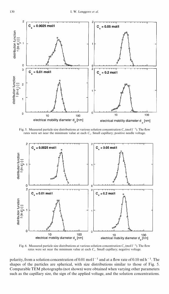
Fig. 5. Measured particle size distributions at various solution concentration C4(mol l~1). The #ow
rates were set near the minimum value at each C4. Small capillary; positive needle voltage.
Fig. 6. Measured particle size distributions at various solution concentration C4(mol l~1). The #ow
rates were set near the minimum value at each C4. Small capillary; negative voltage.
polarity, from a solution concentration of 0.01 mol l~1 and at a #ow rate of 0.10 ml h~1. Theshapes of the particles are spherical, with size distributions similar to those of Fig. 5.Comparable TEM photographs (not shown) were obtained when varying other parameterssuch as the capillary size, the sign of the applied voltage, and the solution concentrations.
130 I. W. Lenggoro et al.
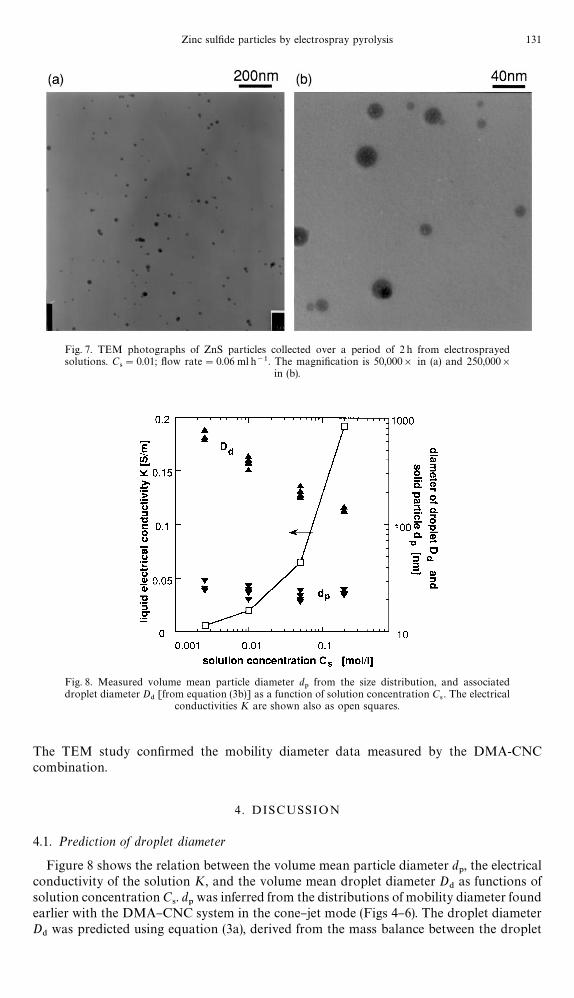
Fig. 7. TEM photographs of ZnS particles collected over a period of 2 h from electrosprayedsolutions. C
4"0.01; #ow rate"0.06 ml h~1. The magni"cation is 50,000] in (a) and 250,000]
in (b).
Fig. 8. Measured volume mean particle diameter d1
from the size distribution, and associateddroplet diameter D
$[from equation (3b)] as a function of solution concentration C
4. The electrical
conductivities K are shown also as open squares.
The TEM study con"rmed the mobility diameter data measured by the DMA-CNCcombination.
4 . DISCUSSION
4.1. Prediction of droplet diameter
Figure 8 shows the relation between the volume mean particle diameter d1, the electrical
conductivity of the solution K, and the volume mean droplet diameter D$
as functions ofsolution concentration C
4. d
1was inferred from the distributions of mobility diameter found
earlier with the DMA}CNC system in the cone}jet mode (Figs 4}6). The droplet diameterD
$was predicted using equation (3a), derived from the mass balance between the droplet
Zinc sul"de particles by electrospray pyrolysis 131

and the "nal solid particle d1
under the assumption that each drop turned into a densespherical particle, without disruption during the spray pyrolysis.
d31"(MD3
$C
4)/1000o, (3a)
where M and o are the molecular weight and the bulk density of solid ZnS, and C4is the
solution concentration in mol l~1. For ZnS with M"97.46 and o"4.09 g cm~3 equation(3a) can be written as
d1"0.288D
$C1@3
4. (3b)
Figure 8 shows a strong dependence of the droplet diameter on the electrical conductivityK of the spray solution. The volume mean droplet diameter D
$ranged from 140 to 580 nm,
and decreased with increasing K. The increased solution concentration led to dry particleswhose size was a larger fraction of the initial droplet size. But it also increased K, whichresulted in smaller droplet sizes. In this study, the overall result of these two factors wasa solid particle size in a narrow range of 20}30 nm, independent of K.
4.2. Size evaluation of droplet and particle based on scaling laws
The scaling laws found in the studies of FernaH ndez de la Mora and Loscertales (1994),Rossel-Llompart and FernaH ndez de la Mora (1994), Chen et al. (1995), Ganan-Calvo et al.(1997) and Chen and Pui (1997) can be used to evaluate the size of the droplets generated inour system. These earlier investigations found that the droplet diameters are nearlyindependent of external electrostatic variables (electrode geometry and voltage), dependingmostly on #ow rate and liquid properties. When the #ow rate ratio Q/Q
.*/takes values not
too large (typically smaller than 16), Rossel-Llompart and FernaH ndez de la Mora (1994) "ndthat the droplets form mainly in a single size, whose initial diameter D*
$scales with the
electrical relaxation length r* de"ned in equation (4a). The following equations can be givenfor the case of polar liquid with electrical permittivity e'6 (see also de Juan and Fernandezde la Mora, 1997 and Ganan-Calvo et al., 1997) and electrical conductivity K typicallylarger than 10~5 Sm~1.
D*$"G(e)r*, (4a)
r*"(Qee0/K)1@3, (4b)
where Q is the #ow rate pushed through the jet and e0
is the electrical permittivity ofvacuum. Available data on G compiled from the literature are shown in Table 2. G dependsmainly on e, but is also in#uenced by the following viscosity variable (Rossel-Llompart andFernaH ndez de la Mora, 1994):
%(k)"(oc2ee0/K)1@3/k, (5)
where c is the surface tension of the liquid. %(k) accounts for viscous e!ect on the jetbreakup, which increases the ratio between the diameter of the drops and that of the jet. Inparticular, the diameter of &&satellite'' droplets made dimensionless with r* depends steeplyon %(k) at values of this parameter below 0.06, but seems to level o! for %(k)'0.15. Table 3shows that %(k) ranges between 0.4 and 2 for the present solutions, for which only slightviscous e!ects should be expected.
The electrical permittivity e and the surface tension c were not measured, and thesesolution properties have been assumed to be equal to those of pure ethanol (c"0.02275Nm~1; e"24.3). G(e) also appeared to be a constant, independent of the dimensionless #owrate parameter g,
g"[oQK/(cee0)]1@2. (6)
At the highest solution concentrations (C4"0.05 and 0.2 mol l~1) the smallest values of
g were as large as 15$2 and 24$3 (Table 3), several times larger than the values g.*/
&1
132 I. W. Lenggoro et al.

Table 2. Values of G(e) [equation (4)] drawn from the literature
Sources e G(e) Note
FernaH ndez de la Mora and Loscertales (1994) &40 0.76 *1Rossel-Llompart and FernaH ndez de la Mora (1994) 20 0.68 *2Aguirre-de-Carcer and FernaH ndez de la Mora (1995) 80 0.60}1.10 *3de Juan and FernaH ndez de la Mora (1997) 81 0.648 *4Chen and Pui (1997) 12.5}182 1.23}0.70 *5
Note:*1 Supported by optical determination of jet diameters.*2 Based on aerodynamics measurements of droplet diameter.*3 Dd of water have been obtained by a phase Doppler anemometry.*4 Droplets of water in a wide range of K, rearranged the data of Chen et al. (1995).*5 Fitted function G(e)"!10.87e~6@5#4.08e~1@3 (water and ethylene glycol solutions).
Table 3. Characteristic of the initial drops electrosprayed (small capillary, positive polarity)
Cs Q d1
D$
g % r* D*$
D*$
(mol l~1) (ml h~1) (nm) (nm) * * (nm) (nm) (nm)(G"0.60) (G"0.75)
0.0025 0.10 22.8 583.6 5.02 2.050 1021.0 612.6 765.80.01 0.07 21.9 353.1 7.95 1.317 592.6 355.6 444.50.05 0.06 23.4 220.7 13.35 0.813 380.1 228.1 285.10.20 0.05 23.8 141.6 21.38 0.432 249.7 149.8 187.3
found in previous studies for polar liquids. This anomaly is also most probably due toconsiderable evaporation in our meniscus. Had we been able to attain smaller #ow ratesand hence produced smaller drops at given K, we should have been able to "nd a decreasein the "nal particle size at increasing K. This is in fact what was seen by Rulison and Flagan,whose evaporative loss problem hence appears to have been milder than ours.
For the present purposes, considering the value of e to be 24.3, G was assumed to bebetween 0.60 and 0.75. Table 3 shows also the calculated data obtained from the experi-mental conditions described in Fig. 5 for the particular case of the small capillary andpositive polarity. The values of D
$given by equation (3) agree best with D*
$calculated by the
scaling laws [equation (4)] when G(e) is 0.60.The experimental data in points of Fig. 9a and b are replotted from Fig. 8. The error bars
do not account for ambiguities in either the value of G(e) ("xed at 0.60 in all calculations ofD*
$), the liquid #ow rate (we used Q
&%%$rather than Q
+%5) or its electrical conductivity (we
used K&%%$
rather than K+%5
). They are associated to the experimental size scatter found ata given solution concentration, the lower bound corresponding to the smaller size observedwhen using the small capillary, and the higher bound to the maximum size measured withthe large capillary. The values of the solid particle diameter used are volume meandiameters. The scaling law predicts initial drop diameters in the ranges of 665$50 nm forthe case of C
4"0.0025 mol l~1, and 163$13 nm for the case of C
4"0.2 mol l~1. The
resulting volume mean particle diameters were predicted to be between 20 and 30 nm.Evaporation modi"es the predicted initial drop diameter, not only by making Q
+%5(
Q&%%$
, but also by increasing the solution concentration near the cone tip. Hence, the localvalue of the electrical conductivity increases, so that K
+%5'K
&%%$. Both e!ects may be
comparable in magnitude in the limit when K is proportional to salt concentration. Theytend to compensate each other in the prediction of the spray current, while they add to eachother in the prediction of the drop diameter. The conductivity would be modi"ed only if thesalt di!usivity were su$cient to spread the salt-enriched surface layer into the interior of themeniscus. Otherwise, C
4would increase only in a narrow outer liquid layer, where the salt
would be greatly enriched and precipitate, more in consonance with our observations athigher concentrations. We may obtain an upper estimate for the error in Q due toevaporation by comparing the observed and predicted currents while taking K
+%5"K
&%%$.
Zinc sul"de particles by electrospray pyrolysis 133

Fig. 9. Data of Fig. 8 [(a) for D$and (b) for d
1] compared to the ranges (error bars) expected from the
scaling laws [equation (4) with G"0.6] for each solution concentration C4.
It ranges from 17 to 40% for C4"0.0025 mol l~1, and up to 85% for C
4"0.2 mol l~1. The
corresponding droplet diameter error is much smaller because of the slow dependence(1/3 power law) of r* on K and Q. It varies in this estimate from 5 to 11% (C
4"0.0025
mol l~1) to around 30% (C4"0.2 mol l~1). Such ambiguities are by no means negligible;
but they are still comparable with the scatter in the data shown in Fig. 9 as well as with theindeterminacy in the value of G. In spite of these uncertainties, Fig. 9 shows a fair agreementbetween predictions and observations, with only a slight overprediction at higher C
4. Hence
one may produce particles of a desired size, just by controlling the physical properties of thesolution and its #ow rate.
The di$culties found here at higher C4should be avoided in the future by spraying the
solution from "ner capillaries, where evaporation may be greatly reduced (Chen et al., 1995).This precaution will also allow a wider range of #ow rate variation, and hence a smaller"nal particle diameter. Elimination of the evaporative problem will also avoid salt precipi-tation and hence increase the spray stability. This will undoubtedly allow approaching theconsiderably narrower size distributions observed in earlier electrospray atomization,which makes us think that mean particle diameters below 10 nm with geometrical standarddeviation p
'below 1.1 should be attainable in electrospray pyrolysis.
We have seen only unimodal size distributions, perhaps because we operate nearminimum #ow rate. Note that at higher Q, a bifurcation phenomenon tends to occur,leading to bimodal particle size distributions (Rossel-Llompart and FernaH ndez de la Mora,1994; de Juan and FernaH ndez de la Mora, 1997). Other possible reasons for the absence ofsmaller satellite drops from our samples is their preferential loss by deposition onto thewalls, or the limitations of our measuring instrumentation. For instance, the size range ofthe DMA is from 5 to 200 nm, while the e$ciency of the CNC is down to 50% at 5 nm.
5. CONCLUSION
The potential of the electrospray pyrolysis technique in the synthesis of nanosizedzinc sul"de particles 20}40 nm in diameter has been demonstrated by on-line size
134 I. W. Lenggoro et al.

measurement with a DMA}CNC system and con"rmed by TEM photographs of collectedsamples. Electrospray can "nely atomize ethyl alcohol solutions of zinc nitrate and thioureaunder a variety of experimental conditions such as: solution concentrations between 0.0025and 0.2 mol l~1; electrical conductivities between 10~4 and 10~1 S m~1; liquid #ow rates ofabout 0.10 ml h~1; positive and negative needle voltages; and various capillary geometries.Neutralization of the highly charged drops initially produced with the bipolar ions from ana-ray radioactive source greatly improves the throughput e$ciency of the generatedparticles. The measured "nal particle sizes are in agreement with a process where solutiondrops are initially electrosprayed with diameters obeying known scaling laws, and then dryinto "nal compact and spherical particles. The smallest particle diameters generated here(&20 nm) and the geometrical standard deviation observed (p
'&1.3) do not represent
fundamental limits of the electrospraying technique used, and could probably be improvedsubstantially by use of narrower capillaries. The novel neutralization technique introducedshould be useful in a considerably wider range of applications than those considered here.
Acknowledgment2The authors wish to thank Mr K. Hayashi (Toda Kogyo Corporation, Hiroshima) for takingthe TEM photographs of the particles, as well as Prof. A. Gomez (Yale) for insights into the subject of dropneutralization. Support from the Ministry of Education, Culture and Science of Japan (Grant No. 08650893), theHosokawa Powder Technology Foundation and the Electric Technology Research Foundation of Chugoku, isgratefully acknowledged. I.W.L. is greatly indebted to the Agency for the Assessment and Application ofTechnology BPPT, Indonesia, for a fellowship.
REFERENCES
Adachi, M., Okuyama, K., Kousaka, Y., Moon, S. W. and Seinfeld, J. H. (1990) Facilitated aerosol sizing using thedi!erential mobility analyzer. Aerosol Sci. ¹echnol. 12, 225}239.
Aguirre-de-Carcer, I. and FernaH ndez de la Mora, J. (1995) E!ect of background gas on the current emitted fromTaylor cones. J. Coll. Interf. Sci. 171, 512}517.
Benassayag, G., Sudraud, P. and Jou!rey, B. (1985) In situ high voltage TEM observations of an EHD source.;ltramicroscopy 16, 1}8.
Bollini, R., Sample, S. B., Seigal, S. D. and Boarman, J. W. (1975) Production of monodisperse charged metalparticles by harmonic electrical spraying. J. Coll. Interf. Sci. 51, 272}277.
Chen, G. and Gomez, A. (1996) Co-#ow laminar di!usion #ames of monodisperse sprays: structure, evaporationand microgravity e!ects. Comb. Sci. ¹echnol. 115, 177}202.
Chen, D. R. and Pui, D. Y. H. (1997) Experimental investigation of scaling laws for electrospraying: dielectricconstant e!ect. Aerosol Sci. ¹echnol. 27, 367}380.
Chen, D. R., Pui, D. Y. H. and Kaufman, S. L. (1995) Electrosprays of conducting liquids for monodisperse aerosolgeneration in the 4 nm to 1.8 km diameter range. J. Aerosol Sci. 26, 963}977.
Cloupeau, M. (1994) Recipes for use of EHD spraying in cone}jet mode and notes on corona discharge e!ects.J. Aerosol Sci. 25, 1143}1157.
Cloupeau, M. and Prunet-Foch, B. (1989) Electrostatic spraying of liquids in cone}jet. J. Electrostat. 22, 135}159.Cloupeau, M. and Prunet-Foch, B. (1990) Electrohydrodynamic spraying functioning of liquids in cone}jet.
J. Electrostat. 25, 165}184.Cloupeau, M. and Prunet-Foch, B. (1994) Electrohydrodynamic spraying functioning modes: a critical review.
J. Aerosol Sci. 25, 1021}1036.de Juan, L. and FernaH ndez de la Mora, J. (1997) Charge and size distributions of electrospray drops. J. Coll. Interf.
Sci. 186, 280}293.Danek, M., Jensen, K. F., Murray, C. B. and Bawendi, M. G. (1994a) Electrospray organometallic chemical vapor
deposition*A novel technique for preparation of II}VI quantum dot composites. Appl. Phys. ¸ett. 65,2795}2797.
Danek, M., Jensen, K. F., Murray, C. B. and Bawendi, M. G. (1996) Synthesis of luminescent thin-"lm CdSe/ZnSequantum dot composites using CdSe quantum dots passivated with an overlayer of ZnSe. Chem. Mater. 8,173}180.
Fenn, J. B., Mann, M., Meng, C. K., Wong, S. F. and Whitehouse, C. M. (1989) Electrospray ionization for massspectrometry of large biomolecules. Science 246, 64}71.
FernaH ndez de la Mora, J. (1992) The e!ect of charge emission from electri"ed liquid cones. J. Fluid Mech. 243,561}574.
FernaH ndez de la Mora, J. and Loscertales, I. G. (1994) The current transmitted through an electri"ed liquid conicalmeniscus. J. Fluid Mech. 260, 155}184.
Ganan-Calvo, A. M., Davila, J. and Barrero, A. (1997) Current and droplet size in the electrospraying of liquidsscaling laws. J. Aerosol Sci. 28, 249}275.
Gurav, A., Kodas, T., Pluym, T. and Xiong, Y. (1993) Aerosol processing of materials. Aerosol Sci. ¹echnol. 19,411}452.
Hull, P. J., Hutchison, J. L., Salata, O. V. and Dobson, P. J. (1997) Synthesis of nanometer-scale silver crystallitesvia a room-temperature electrostatic spraying process. Adv. Mater. 9, 413}416.
Jensen, H. and Sorensen, G. (1996) Ion bombardment of nano-particle coatings. Surf. Coatings ¹echnol. 84,500}505.
Zinc sul"de particles by electrospray pyrolysis 135

Jones, A. R. and Thong, K. C. (1971) The production of charged monodisperse fuel droplets by electrostaticdispersion. J. Phys. D 4, 1159}1166.
Kaufman, S. L., Skogen, J. W., Dorman, F. D., Zarrin, F. and Lewis, K. C. (1996) Macromolecule analysis based onelectrophoretic mobility in air: Globular proteins. Anal. Chem. 68, 1895}1904. See also correction Anal. Chem.68, 3703 (1996).
Lenggoro, I. W., Kang, Y. C., Komiya, T., Okuyama, K. and Tohge, N. (1998) Formation of submicron coppersul"de particles using spray pyrolysis method. Jpn. J. Appl. Phys. 37, L288}L290.
Levi, C. G., Jayaram, V., Valencia, J. J. and Mehrabian, R. (1988) Phase selection in electrohydrodynamicatomization of alumina. J. Mater. Res. 3, 969}983.
Lewis, K. C., Dohmeier, D. M., Jorgensen, J. W., Kaufman, S. L., Zarrin, F. and Dorman, F. D. (1994)Electrospray-condensation particle counter: a molecule-counting LC detector for macromolecules. Anal. Chem.66, 2285}2292.
Mahoney, J. F., Taylor S. and Perel, J. (1987) Fine powder production using electrohydrodynamic atomization.IEEE ¹rans. Ind. Appl. IA-23, 197}204.
Meesters, G. M. H., Vercoulen, P. H. W., Marijnissen, J. C. M. and Scarlett, B. (1992) Generation of micron-sizeddroplets from the Taylor cone. J. Aerosol Sci. 23, 37}49.
Meshing, G. L., Zhang, S. C. and Jayanthi, G. (1993) Ceramic powder synthesis by spray pyrolysis. J. Am. Ceram.Soc. 76, 2707}2726.
Noakes, T. J., Pavey, I. D., Bray, D. and Rowe, R. C. (1989) Apparatus for producing a spray of droplets of a liquid.;.S. Patent, 4829996.
Okuyama, K., Lenggoro, I. W., Tagami, N., Tamaki, S. and Tohge, N. (1996) Formation of ultra"ne particles ofmetal sul"de by electrostatic spray pyrolysis method. J. Soc. Powder ¹echnol. Jpn. 33, 192}198.
Okuyama, K., Lenggoro, I. W., Tagami, N., Tamaki, S. and Tohge, N. (1997) Preparation of ZnS and CdS "neparticles with di!erent particle sizes by a spray-pyrolysis method. J. Mater. Sci. 32, 1229}1237.
Park, D. G. and Burlitch, J. M. (1992) Nanoparticles of anatase by electrostatic spraying of an alkoxide solution.Chem. Mater. 4, 500}503.
Reneker, D. H. and Chun, I. (1996) Nanometre diameter "bres of polymer produced by electrospinning.Nanotechnology 7, 216}223.
Rossel-Llompart, J. and FernaH ndez de la Mora, J. (1994) Generation of monodisperse droplets 0.3 to 4 km indiameter from electri"ed cone}jets of highly conducting and viscous liquids. J. Aerosol Sci. 25, 1093}1120.
Rulison, A. J. and Flagan, R. C. (1994a) Electrospray atomization of electrolytic solutions. J. Coll. Interf. Sci. 167,135}145.
Rulison, A. J. and Flagan, R. C. (1994b) Synthesis of yttria powders by electrospray pyrolysis. J. Amer. Ceram. Soc.77, 3244}3250.
Salata, O. V., Dobson, P. J., Hull, P. J. and Hutchison, J. L. (1994) Fabrication of PbS nanoparticles embedded ina polymer "lm by a gas-aerosol reactive electrostatic deposition technique. Adv. Mater. 6, 772}775.
Slamovich, E. B. and Lange, F. F. (1990) Densi"cation behavior of single-crystal and polycrystalline sphericalparticles of zirconia. J. Am. Ceram. Soc. 73, 3368}3375.
Smith, D. P. H. (1986) The electrohydrodynamic atomization of liquids. IEEE ¹rans. Ind. Appl. IA-22, 527}535.Sobota, J. and Sorensen, G. (1997) Ion bombardment of solid lubricating nanoparticle coatings. Nucl. Inst.
Methods Phys. Res.-Sect.B- Beam Interact. Mater. Atoms 127, 945}948.Tang, K. and Gomez, A. (1995) Generation of monodisperse water droplets from electrosprays in a corona-assisted
cone}jet mode. J. Coll. Interf. Sci. 175, 326}332.Tang, K. and Gomez, A. (1996) Monodisperse electrosprays of low electric conductivity liquids in the cone-jet
mode. J. Coll. Interf. Sci. 184, 500}511.Taylor, G. I. (1964) Disintegration of water drops in an electric "eld. Proc. Roy. Soc. ¸ondon A 280, 383}397.Teng, W. D., Huneiti, Z. A., Machowski, W., Evans, J. R. G., Edirisinghe, M. J. and Balachandran, W. (1997)
Towards particle-by-particle deposition of ceramics using electrostatic atomization. J. Mater. Sci. ¸ett. 16,1017}1019.
Thong, K. C. and Weinberg, F. J. (1971) Electrical control of the combustion of solid and liquid particulatesuspensions. Proc. Roy. Soc. ¸ondon A 324, 201}215.
Tohge, N. and Minami, T. (1992) Formation process of Cd and Zn chalcogenide-doped glasses via gels containingthiourea or selenourea complexes. SPIE Proc. Sol}Gel Optics II 1758, 587}595.
Tohge, N., Tamaki, S. and Okuyama, K. (1995) Formation of "ne particles of zinc sul"de from thiourea complexesby spray-pyrolysis. Jpn. J. Appl. Phys. 34-2, L207}L209.
Zarrin, F., Kaufman, S. L. and Dorman, F. D. (1991a) Method and apparatus for determining concentration ofmacromolecules and colloids in a liquid sample. ;.S. Patent, 5076097.
Zarrin, F., Kaufman, S. L. and Socha, J. R. (1991b) Droplet size measurement of various nebulizer using di!erentialelectrical mobility particle sizer. J. Aerosol Sci. 22, S343}346.
Zeleny, J. (1915) On the conditions of instability of liquid drops, with applications to the electrical discharge fromliquid point. Proc. Camb. Phil. Soc. 18, 71}83.
136 I. W. Lenggoro et al.