Embed Size (px)
Citation preview

Standard Technical Specification – Preparation of Electrical Engineering Drawings TRIM: HW2009-2368/2/24
Warning – This document is current at time of printing or downloading. It may be reviewed and amended prior to the noted review date at the discretion of Hunter Water Corporation.
Version: 1.0 Page 1 of 31
Date Approved:
Hunter Water Corporation A.B.N. 46 228 513 446
Standard Technical Specification for:
PREPARATION OF ELECTRICAL ENGINEERING DRAWINGS
STS904
This Standard Technical Specification was developed by Hunter Water Corporation to be used for the
design, construction/installation and/or maintenance of facilities that are, or are to become, the property of
Hunter Water Corporation. It is intended that this Standard Technical Specification be used in conjunction
with various other standard and project specific drawings and design requirements as defined by Hunter
Water Corporation for each particular project.
Hunter Water Corporation does not consider this Standard Technical Specification suitable for use for any
other purpose or in any other manner. Use of this Standard Technical Specification for any other purpose or
in any other manner is wholly at the user's risk.
Hunter Water Corporation makes no representations or warranty that this Standard Technical Specification
has been prepared with reasonable care and does not assume a duty of care to any person using this
document for any purpose other than stated.
In the case of this document having been downloaded from Hunter Water Corporation's website;
- Hunter Water Corporation has no responsibility to inform you of any matter relating to the accuracy of this
Standard Technical Specification which is known to Hunter Water Corporation at the time of downloading
or subsequently comes to the attention of Hunter Water Corporation.
- This document is current at the date of downloading. Hunter Water Corporation may update this
document at any time.
Copyright in this document belongs to Hunter Water Corporation.
Standard Technical Specification – Preparation of Electrical Engineering Drawings TRIM: HW2009-2368/2/24
Warning – This document is current at time of printing or downloading. It may be reviewed and amended prior to the noted review date at the discretion of Hunter Water Corporation.
Version: 1.0 Page 2 of 31
Date Approved:
Table of Contents
1 Purpose .................................................................................................................. 5
2 Interpretation ......................................................................................................... 6
2.1 Order of Precedence ..................................................................................................... 6
3 Roles and Responsibilities ................................................................................... 7
3.1 Document Owner .......................................................................................................... 7
3.2 Responsibilities ............................................................................................................. 7
4 Definitions ............................................................................................................. 8
5 Compliance Requirements ................................................................................... 9
5.1 Standards ...................................................................................................................... 9
5.2 Copyright ....................................................................................................................... 9
6 Drawing Requirements ....................................................................................... 11
6.1 Information Provided by Hunter Water ........................................................................ 11
6.2 File Format .................................................................................................................. 11
6.3 Drawing Size ............................................................................................................... 11
6.4 Drawing Numbers ....................................................................................................... 12
6.4.1 Electronic File Name ........................................................................................... 12
6.5 Drawing Specifications ................................................................................................ 12
6.5.1 Drawing Environment .......................................................................................... 12
6.5.2 Text Styles ........................................................................................................... 13
6.5.3 Dimensioning ....................................................................................................... 14
6.5.4 Linetypes ............................................................................................................. 16
6.5.5 Layers .................................................................................................................. 17
6.5.6 Title Block Information ......................................................................................... 17
6.5.7 External References ............................................................................................ 17
6.5.8 Plotted Drawing Identification .............................................................................. 17
6.5.9 Hatching .............................................................................................................. 18
6.5.10 Symbols, Blocks and Abbreviations ................................................................ 18
6.5.11 Signatories ...................................................................................................... 19
6.5.12 Other ............................................................................................................... 19
6.6 Supply of Drawings ..................................................................................................... 20

Standard Technical Specification – Preparation of Electrical Engineering Drawings TRIM: HW2009-2368/2/24
Warning – This document is current at time of printing or downloading. It may be reviewed and amended prior to the noted review date at the discretion of Hunter Water Corporation.
Version: 1.0 Page 3 of 31
Date Approved:
6.6.1 Revisions ............................................................................................................. 20
6.6.2 Highlighting Revisions ......................................................................................... 21
6.6.3 Work As Constructed .......................................................................................... 21
6.7 Completed Drawings ................................................................................................... 22
6.7.1 Final Drawing Settings ........................................................................................ 22
6.7.2 Company Logos .................................................................................................. 22
6.7.3 Drawing Register Details ..................................................................................... 22
6.7.4 Transmittals ......................................................................................................... 22
6.8 Technical Presentation ................................................................................................ 23
6.8.1 Wire Numbering .................................................................................................. 23
6.8.2 Cross Referencing............................................................................................... 24
6.8.3 Component Ratings and Settings ....................................................................... 24
6.9 Drawings Prepared Prior to the First Issue of STS904 ............................................... 26
6.9.1 Revisions ............................................................................................................. 26
6.9.2 Electronic File Name ........................................................................................... 26
6.9.3 Drawing Title ....................................................................................................... 26
6.9.4 Revision Description ........................................................................................... 27
6.9.5 Redrawing TIF Files ............................................................................................ 27
6.9.6 Plot Style ............................................................................................................. 27
6.9.7 Drawing Register Details ..................................................................................... 27
7 Related Documents ............................................................................................. 28
8 Document Control ............................................................................................... 29

Standard Technical Specification – Preparation of Electrical Engineering Drawings TRIM: HW2009-2368/2/24
Warning – This document is current at time of printing or downloading. It may be reviewed and amended prior to the noted review date at the discretion of Hunter Water Corporation.
Version: 1.0 Page 4 of 31
Date Approved:
FIGURES
Figure 1: Dimensions .................................................................................................................................. 14
TABLES
Table 1: Documentation Provided by Hunter Water ................................................................................... 11
Table 2: Text Styles .................................................................................................................................... 13
Table 3: Multileader Style Manager ............................................................................................................ 15
Table 4: Standard AutoCad Linetypes ........................................................................................................ 16
Table 5: Linetypes ....................................................................................................................................... 16
Table 6: Drawing Title Examples ................................................................................................................ 17
Table 7: Print Layout Setup......................................................................................................................... 18
Table 8: Signatories .................................................................................................................................... 19
Table 9: Drawing Suffix List ........................................................................................................................ 23
APPENDICIES
Appendix 1. Australian Standards ....................................................................... 30
Appendix 2. Drawing Layers ................................................................................ 31

Standard Technical Specification – Preparation of Electrical Engineering Drawings TRIM: HW2009-2368/2/24
Warning – This document is current at time of printing or downloading. It may be reviewed and amended prior to the noted review date at the discretion of Hunter Water Corporation.
Version: 1.0 Page 5 of 31
Date Approved:
Standard Technical Specification Electrical
Engineering Drawings – STS904
1 Purpose
This Standard Technical Specification details the preparation and submission of all electrical engineering
design drawings to Hunter Water Corporation (Hunter Water).
It does not cover requirements for
Work as Constructed (WAC) Drawings specified in STS903
Civil, Structural and Mechanical Drawings specified in STS911
This Specification is available on the Hunter Water website http://www.hunterwater.com.au.

Standard Technical Specification – Preparation of Electrical Engineering Drawings TRIM: HW2009-2368/2/24
Warning – This document is current at time of printing or downloading. It may be reviewed and amended prior to the noted review date at the discretion of Hunter Water Corporation.
Version: 1.0 Page 6 of 31
Date Approved:
2 Interpretation
For the purposes of the interpretation of STS904, except where the context requires otherwise:
'Drawings' means the drawings detailing the work involved in a particular project
‘Include’ means including but not limited to, and is used to provide clarification or examples of the
type and nature of items intended
'Specification' means a specification detailing the work involved in a particular project
‘Standards’ means applicable industry standards including the Australian Standards (AS),
Australian / New Zealand Standards (AS/NZS) and ISO Standards (ISO)
'Standard Drawings' means Hunter Water Corporation drawings
'Standard Technical Specification' (STS) is a reference to any of Hunter Water’s Standard
Technical Specifications, as implied by the text.
Headings are for the convenience of the reader and shall not be used in the interpretation of this STS.
Unless stated otherwise any expression such as "give notice", "submit", "approval", or "directed" means
give notice to, submit to, approval by, or directed by the person nominated by Hunter Water.
Approval does not imply acceptance of responsibility by Hunter Water for compliance with this STS.
Unless approval has been issued in writing by Hunter Water, approval has not been granted.
2.1 Order of Precedence
The order of precedence of technical documents for a project should be stated in the project’s
documentation. The hierarchy of specifications are:
1. Specification, Drawings, Standard Drawings (project documents)
2. Facility related STS
3. Equipment related STS
4. STS904

Standard Technical Specification – Preparation of Electrical Engineering Drawings TRIM: HW2009-2368/2/24
Warning – This document is current at time of printing or downloading. It may be reviewed and amended prior to the noted review date at the discretion of Hunter Water Corporation.
Version: 1.0 Page 7 of 31
Date Approved:
3 Roles and Responsibilities
3.1 Document Owner
The Document Owner of this STS is the Manager Asset Management.
3.2 Responsibilities
Any request for a variation to this STS shall be made in accordance with the change management
process in Hunter Water Asset Standards Management Plan.
The Document Owner shall approve in writing the issue of any updates.
Standard Technical Specification – Preparation of Electrical Engineering Drawings TRIM: HW2009-2368/2/24
Warning – This document is current at time of printing or downloading. It may be reviewed and amended prior to the noted review date at the discretion of Hunter Water Corporation.
Version: 1.0 Page 8 of 31
Date Approved:
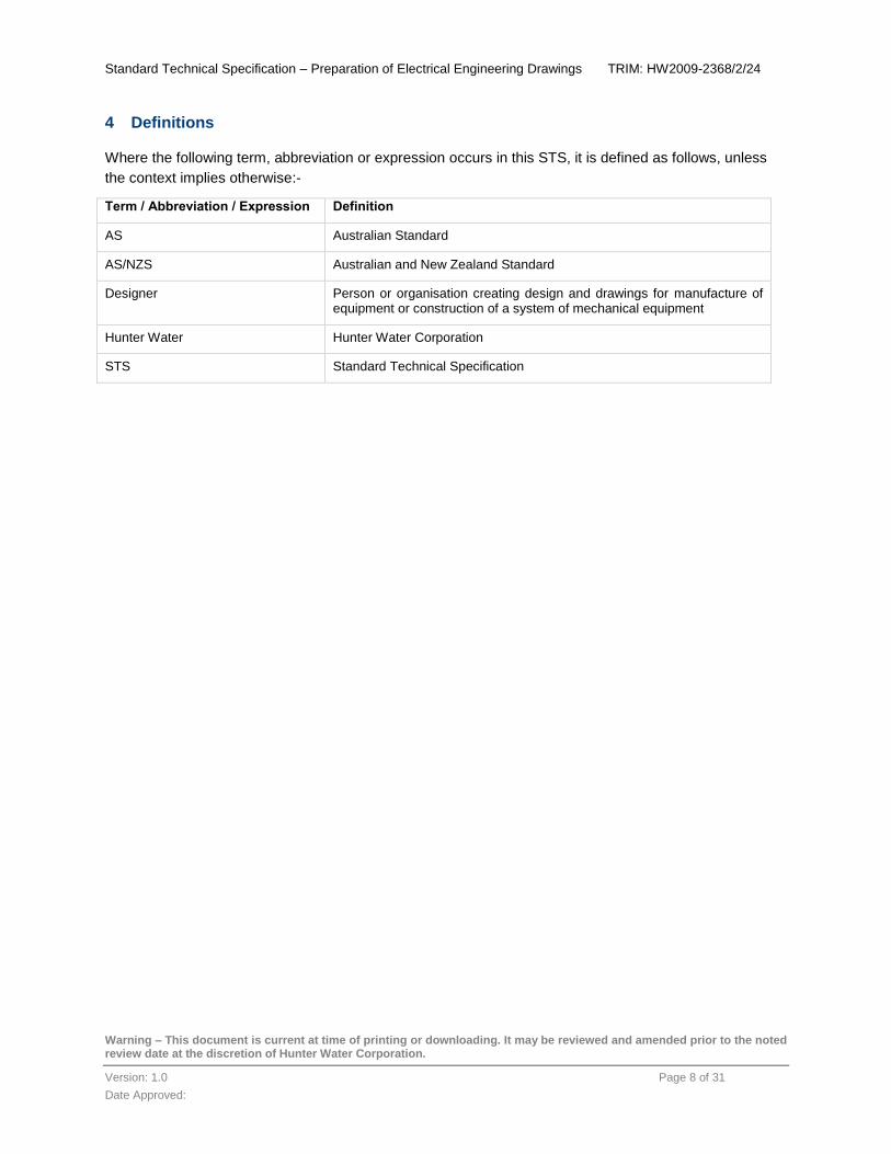
4 Definitions
Where the following term, abbreviation or expression occurs in this STS, it is defined as follows, unless
the context implies otherwise:-
Term / Abbreviation / Expression Definition
AS Australian Standard
AS/NZS Australian and New Zealand Standard
Designer Person or organisation creating design and drawings for manufacture of equipment or construction of a system of mechanical equipment
Hunter Water Hunter Water Corporation
STS Standard Technical Specification

Standard Technical Specification – Preparation of Electrical Engineering Drawings TRIM: HW2009-2368/2/24
Warning – This document is current at time of printing or downloading. It may be reviewed and amended prior to the noted review date at the discretion of Hunter Water Corporation.
Version: 1.0 Page 9 of 31
Date Approved:
5 Compliance Requirements
5.1 Standards
Electrical drawings shall comply with:
This STS
Other relevant Hunter Water Standards
Relevant Australian Standards
Except where otherwise required in this specification, drawings are to comply with the current relevant
Standards including, but not limited to those found in Appendix 1.
Any deviation from STS904 shall be approved in writing on a case by case basis by an authorised Hunter
Water representative.
5.2 Copyright
All electronic files supplied by Hunter Water are the property of Hunter Water. This includes, but is not
limited to, the contents of the Technical Information Package, including the Microsoft Office format files,
AutoCAD format files and associated files, menus, plug-ins, code and scripts (Files). Hunter Water retains
all intellectual property and related rights in or relating to the Files including without limitation copyright
(including future copyright); confidential information, and all other rights conferred by statute, common law
or equity in relation to the Files.
The purpose of the Files is to assist the user in the production of electrical drawings for Hunter Water in
accordance with this Standard Technical Specification and to confirm whether electrical drawings
produced for Hunter Water are compliant with this STS (Intended Use).
The Files are not to be used, copied, modified, manipulated, supplied, reproduced, provided or disclosed
by or to any other person or for any purpose other than the Intended Use without the prior written consent
of Hunter Water.
To the extent permitted by law, all conditions and warranties concerning the Files expressed or implied by
statute, common law, equity, trade, custom or usage or otherwise are expressly excluded. Hunter Water
makes no representation as to the stability of the Files and accepts no liability for any loss or damage
arising from the instability of the Files.
Hunter Water is not required to provide maintenance support for the Files or detailed instructions on
operational use.

Standard Technical Specification – Preparation of Electrical Engineering Drawings TRIM: HW2009-2368/2/24
Warning – This document is current at time of printing or downloading. It may be reviewed and amended prior to the noted review date at the discretion of Hunter Water Corporation.
Version: 1.0 Page 10 of 31
Date Approved:
The user must ensure that the Files are:
Used in accordance with any instructions provided by Hunter Water
Used appropriately and only for such of the Intended Use
Only used, accessed, operated, and copied by, or provided to persons who are officers,
employees or agents of the user and are aware of and have agreed to be bound by these terms
and conditions
The user acknowledges that a zero error report by the compliance checking files does not guarantee that
the drawings checked are compliant with this STS.
The user indemnifies and will keep indemnified Hunter Water against all actions, suits, claims, demands,
costs, charges, damages, liabilities, loss and expenses to which Hunter Water may incur arising out of the
provision to the user of, and any use, reproduction or disclosure of or change to, the Files by the user or
any other person claiming through the user, which is in any way connected with or arises from the use of
the Files.
Drawing files submitted to Hunter Water shall become the copyright property of Hunter Water

Standard Technical Specification – Preparation of Electrical Engineering Drawings TRIM: HW2009-2368/2/24
Warning – This document is current at time of printing or downloading. It may be reviewed and amended prior to the noted review date at the discretion of Hunter Water Corporation.
Version: 1.0 Page 11 of 31
Date Approved:
6 Drawing Requirements
6.1 Information Provided by Hunter Water
Prior to commencement of a design, or modification of an existing drawing package, it is the responsibility
of the designer to obtain the following information from Hunter Water, and ensure the drawing package is
the latest revision.
Hunter Water Electrical Drafting has template drawings available to the Contractor in the form of a
Technical Information Package.
A meeting with Hunter Water Electrical Drafting prior to commencement is strongly advised if this is the
first time the Contractor has carried out drafting for Hunter Water.
The following information is provided by Hunter Water:
Table 1: Documentation Provided by Hunter Water
Information Contact at Hunter Water
Equipment Number Hunter Water Project Manager
Asset Name Hunter Water Project Manager
Drawing Set Number [email protected]
Technical Information Package including electronic copy of the standard electrical menu, borders, symbols and template drawing set
prior to commencement of each project
6.2 File Format
Drawings shall be supplied in an AutoCad version which is two versions prior to the current Autocad
release.
6.3 Drawing Size
Draw all electrical schematics, switchboard constructions, and layouts on an A3 size sheet.
A1 drawing sizes may be used upon request from Hunter Water Electrical Drafting. If approved, the
Hunter Water standard A1 border will be provided.

Standard Technical Specification – Preparation of Electrical Engineering Drawings TRIM: HW2009-2368/2/24
Warning – This document is current at time of printing or downloading. It may be reviewed and amended prior to the noted review date at the discretion of Hunter Water Corporation.
Version: 1.0 Page 12 of 31
Date Approved:
6.4 Drawing Numbers
The drawing number consists of three segments of information inserted in the title block as follows:
Drawing set
Sheet number ( two digits & three digits if over 100 sheets)
Revision number (one digit)
An example of a drawing number is shown below:
SK12345 01 2
Drawing Set Sheet Number
Revision Number
or
SK12345 101 2
Drawing Set Sheet Number
Revision Number
All drawings submitted to Hunter Water shall only have drawing set numbers provided by Hunter Water.
6.4.1 Electronic File Name
The name of the electronic drawing files are to reflect the drawing number, but an extra zero is to be
inserted in front of the sheet number if two digits and in front of the revision number. A dash is inserted
between the drawing set number and sheet number, an underscore is inserted between the sheet number
and the revision number. For the above example the digital file name would be SK12345-001_02 or
SK12345-101_02.
The drawing title page will be on Sheet 00 and the drawing index is on Sheet 01.
6.5 Drawing Specifications
6.5.1 Drawing Environment
All electrical single line, schematic and connection diagrams are to be produced as a 2D drawing file
using only Model Space.
Panel layouts and construction diagrams along with general arrangements are to be produced using a
combination of Model and Paper Space. The drawing shall be drawn at a 1:1 scale in Model Space and
the border inserted in Paper Space. Viewports are to be created to show the drawing in Paper Space.
Standard scales of Viewports are to be used.
Only one drawing per file; i.e. no multiple Paper Space tabs containing more than one drawing.

Standard Technical Specification – Preparation of Electrical Engineering Drawings TRIM: HW2009-2368/2/24
Warning – This document is current at time of printing or downloading. It may be reviewed and amended prior to the noted review date at the discretion of Hunter Water Corporation.
Version: 1.0 Page 13 of 31
Date Approved:
6.5.1.1 Scaling
All electrical single line, schematic and connection diagrams are to be drawn at a 1:1 scale. Construction
and layout drawings of electrical panels will also be drawn at a 1:1 scale, but may be scaled using the
Viewports and Paper Space mode as detailed in Section 6.5.1.
6.5.1.2 Borders
Only use the standard border provided by Hunter Water.
All borders are to be inserted as a block at 0,0,0 and are not to be exploded or modified.
6.5.2 Text Styles
All text is in accordance with the table below:
Table 2: Text Styles
Text Height Plotted Height
Layer Colour Font Style Width Factor
Oblique Angle
2.0mm - references
TEXT20 ByLayer ISOCP T20 1 0
2.0mm – wire number only
Wire ByLayer ISOCP Wire 1 15
2.5mm TEXT25 ByLayer ISOCP T25 1 0
3.5mm TEXT35 ByLayer ISOCP T35 1 0
5.0mm TEXT50 ByLayer ISOCP T50 1 0
7.0mm TEXT70 ByLayer ISOCP T70 1 0
All general text in the drawing shall be Dtext and is to be horizontal and upper case. Only use lower case
lettering for abbreviations for engineering units of measure. Mtext only permitted for multileader objects.
Annotative text is a property that belongs to objects that are commonly used to annotate drawings. This
property allows you to automate the process of scaling annotations. Annotative objects are set to Paper
Space defined height, and displayed in layout viewports and model space at the size determined by the
annotation scale set for those spaces. Annotative text is to be used when drawing panel layouts, etc.

Standard Technical Specification – Preparation of Electrical Engineering Drawings TRIM: HW2009-2368/2/24
Warning – This document is current at time of printing or downloading. It may be reviewed and amended prior to the noted review date at the discretion of Hunter Water Corporation.
Version: 1.0 Page 14 of 31
Date Approved:
6.5.3 Dimensioning
All dimensions are shown in millimetres. Only solid arrowheads will be used to terminate a dimension line
or leader. Align dimension text parallel to the dimension line as shown below.
Use dimension style as found in AS1100 and multileader style ‘Standard’ as provided with the standard
borders and template drawings.
Note: Annotative scaling can be used to control the overall scale of dimensions displayed in
layout viewports. When you create annotative dimensions, they are scaled based on the current
annotation scale setting and automatically displayed at the correct size.
Dimensions and leaders to be drawn in Paper Space (as per template drawing set).
Incorrect Correct
Figure 1: Dimensions

Standard Technical Specification – Preparation of Electrical Engineering Drawings TRIM: HW2009-2368/2/24
Warning – This document is current at time of printing or downloading. It may be reviewed and amended prior to the noted review date at the discretion of Hunter Water Corporation.
Version: 1.0 Page 15 of 31
Date Approved:
6.5.3.1 Leaders
All leaders to be placed onto layer TEXT20 and formatted as follows:
Table 3: Multileader Style Manager
Leader Format
General Type
Colour
Linetype
Lineweight
Straight
ByLayer
ByLayer
ByLayer
Arrowhead Symbol
Size
Closed filled
2.5
Leader Break Break size 2.5
Leader Structure
Constraints Maximum leader points 2
Landing settings Automatically include landing
Set landing distance
Selected
2.5
Scale Annotative
Specify scale
Selected
1
Content
Multileader type: Mtext (only time Mtext is permitted)
Text options: Default text
Text Style
Text Angle
Text Colour
Text Height
Default text
T20
Keep horizontal
ByLayer
Defaults to 2.0
Leader connection: Horizontal attachment
Left attachment
Right attachment
Landing gap
Selected
Middle of top line
Middle of top line
2.5
Standard Technical Specification – Preparation of Electrical Engineering Drawings TRIM: HW2009-2368/2/24
Warning – This document is current at time of printing or downloading. It may be reviewed and amended prior to the noted review date at the discretion of Hunter Water Corporation.
Version: 1.0 Page 16 of 31
Date Approved:
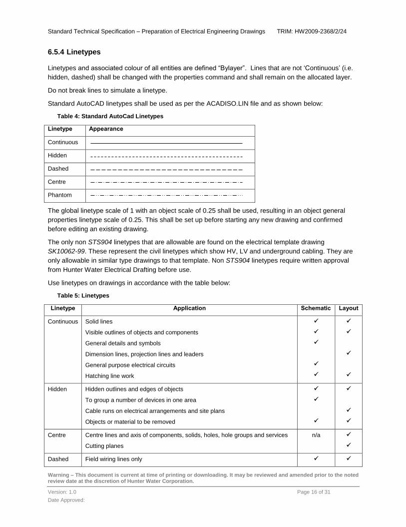
6.5.4 Linetypes
Linetypes and associated colour of all entities are defined “Bylayer”. Lines that are not ‘Continuous’ (i.e.
hidden, dashed) shall be changed with the properties command and shall remain on the allocated layer.
Do not break lines to simulate a linetype.
Standard AutoCAD linetypes shall be used as per the ACADISO.LIN file and as shown below:
Table 4: Standard AutoCad Linetypes
Linetype Appearance
Continuous
Hidden
Dashed
Centre
Phantom
The global linetype scale of 1 with an object scale of 0.25 shall be used, resulting in an object general
properties linetype scale of 0.25. This shall be set up before starting any new drawing and confirmed
before editing an existing drawing.
The only non STS904 linetypes that are allowable are found on the electrical template drawing
SK10062-99. These represent the civil linetypes which show HV, LV and underground cabling. They are
only allowable in similar type drawings to that template. Non STS904 linetypes require written approval
from Hunter Water Electrical Drafting before use.
Use linetypes on drawings in accordance with the table below:
Table 5: Linetypes
Linetype Application Schematic Layout
Continuous Solid lines
Visible outlines of objects and components
General details and symbols
Dimension lines, projection lines and leaders
General purpose electrical circuits
Hatching line work
Hidden Hidden outlines and edges of objects
To group a number of devices in one area
Cable runs on electrical arrangements and site plans
Objects or material to be removed
Centre Centre lines and axis of components, solids, holes, hole groups and services
Cutting planes
n/a
Dashed Field wiring lines only

Standard Technical Specification – Preparation of Electrical Engineering Drawings TRIM: HW2009-2368/2/24
Warning – This document is current at time of printing or downloading. It may be reviewed and amended prior to the noted review date at the discretion of Hunter Water Corporation.
Version: 1.0 Page 17 of 31
Date Approved:
6.5.5 Layers
Layers shall be in accordance with the table in Appendix 2.
6.5.6 Title Block Information
6.5.6.1 Drawing Title
Drawing titles identify the drawing in the context of Hunter Water’s Asset Management System. The
drawing title includes the site name, asset number and functional area to which the drawing refers, as
well as the specific detail of the drawing’s content. Do not use ‘No.’ or ‘#’ to signify the number of the
pump station or pump, refer to examples.
Table 6: Drawing Title Examples
Title Line
Format Pump Station Treatment Plant
1 Asset Name (Equipment Number)
CARDIFF SOUTH 1 WPS (WSCAS015)
BELMONT WWTW (STBEL)
2 Sub Plant Area PUMP 1 SOFT STARTER CONTROL CIRCUIT
INLET WORKS / MCC6000
3 Equipment Description 24VDC PLC CONTROL CLARIFIER PUMP 1 – MV1234
4 Drawing Type SCHEMATIC DIAGRAM SCHEMATIC DIAGRAM
5 Sheet Data SHEET 1 OF 2 SHEET 1 OF 2
6.5.6.2 Revision Table
The revision table in left-hand corner of border is to have the latest revision on the top line at all times and
the revisions shall read from latest to earliest, top to bottom. If the revision table is full the earliest revision
is removed from the list and the latest is put on the top line. The revision description is to reflect what has
been changed on the drawing. i.e. WAC - PLC UPGRADE as detailed in Section 6.6.3.
6.5.7 External References
External references (drawing dependent on another file) on electronic drawings are not permitted. All
external references must be bound prior to submission.
6.5.8 Plotted Drawing Identification
The plot style supplied with the Technical Information Package must be used. The drawing must be
saved using this plot style; there will be no variations to this. The plot style is named HWC-ELEC. All
drawings will be saved using this plot style.
All drawings must be saved with the plotter / printer name being the ‘Default Windows system printer’ and
the paper size ‘A3’ as follows:

Standard Technical Specification – Preparation of Electrical Engineering Drawings TRIM: HW2009-2368/2/24
Warning – This document is current at time of printing or downloading. It may be reviewed and amended prior to the noted review date at the discretion of Hunter Water Corporation.
Version: 1.0 Page 18 of 31
Date Approved:
6.5.8.1 Page Setup Manager / Printer Setup
Create new layouts as follows:
Table 7: Print Layout Setup
Layout A3 Model A3 Layout A4 Model A4 Layout
Plot Style Table HWC-ELEC.ctb HWC-ELEC-A4.ctb
Paper size A3 (297 x 420mm) A4 (210 x 297mm)
Plot Scale 1:1 Fit to paper
Printer/plotter Default Windows System Printer.pc3
Shaded viewport options Quality – Normal
Shade plot – As displayed
Plot Area Extents
Plot offset Centre the plot
Drawing Orientation Landscape
Plot options Plot object lineweights
Plot with plot styles
Plot paper space last
6.5.9 Hatching
Use standard AutoCAD defined hatch patterns for all shading requirements. Do not explode hatching
patterns.
6.5.10 Symbols, Blocks and Abbreviations
Use standard Hunter Water symbols on the drawings. These are located in the Technical Information
Package. To receive a copy, refer to Section 6.1.
Where a symbol/block for an item of equipment or detail is not available from the Hunter Water standard
list, obtain approval in writing from Hunter Water Electrical Drafting before use of the symbol. If new
blocks are to be drawn, they are to be created on layer “symbol” with their attributed tag name and
reference and change the text to layer symbol, bylayer, colour and the colour of the text.
Do not create blocks on any other standard layer.
Do not insert blocks with different X, Y and Z scales.
For each particular drawing, blocks shall be inserted at the same scale every time they are used; (i.e. X =
1, Y =1, Z=1))
Do not explode blocks provided by Hunter Water.

Standard Technical Specification – Preparation of Electrical Engineering Drawings TRIM: HW2009-2368/2/24
Warning – This document is current at time of printing or downloading. It may be reviewed and amended prior to the noted review date at the discretion of Hunter Water Corporation.
Version: 1.0 Page 19 of 31
Date Approved:
See drawing set SK10055 for full details of Hunter Water blocks and symbols, which will be supplied in
the Technical Information Package. This set is supplied as a PDF and is for reference only.
Use abbreviations where appropriate. List and define abbreviations on the Abbreviations and Symbols
drawing.
6.5.11 Signatories
The following drawing review and approval information is required on the title bock.
Table 8: Signatories
Signatory Information to be Included
Designed The name of the designer certifying that the design requirements for the project (including technical standards) have been met. Abbreviate the name by using the designer’s three initials.
The date on which the designer has certified the above.
The abbreviated name of the company for which the designer is employed.
Drawn The name of the draftsperson who prepared the drawing. Abbreviate the name by using the draftsperson’s three initials.
The date for which the draftsperson has completed the above.
The abbreviated name of the company for which the draftsperson is employed.
Checked The name of the appropriate design team leader verifying that an independent examination of the engineering design and drawing has been carried out to confirm compliance with design standards, accuracy of content and conformance with accepted good practice. Abbreviate the name by using the design team leader’s three initials. The design team leader is typically not the same person who has completed the design / drafting.
The date for which the design team leader has completed the above.
The abbreviated name of the company for which the design team leader is employed.
Approved The name of the delegated officer confirming that the drawing meets the requirements of the project and that the drawing can be issued for use. The person approving the drawing is typically not the same person who has checked / designed or has completed the drawing.
The date for which the delegated officer has verified the above.
The abbreviated name of the company for which the delegated officer is employed.
Date Drawn Dates are to be shown with a ‘Dot’ separation and with two digits for day, month and year; e.g. 01.01.11
Formats which are not acceptable include 1.1.11, 1/1/11, 01-01-11 and 01/01/11
6.5.12 Other
6.5.12.1 Grids and Grid Snap
A grid of 5.0mm and a snap of 1.25mm shall be used to ensure that all sectors align correctly. Text where
applicable is to be positioned using a 5.0mm grid, 1.25mm snap to ensure a 1.25mm gap between
objects and text.

Standard Technical Specification – Preparation of Electrical Engineering Drawings TRIM: HW2009-2368/2/24
Warning – This document is current at time of printing or downloading. It may be reviewed and amended prior to the noted review date at the discretion of Hunter Water Corporation.
Version: 1.0 Page 20 of 31
Date Approved:
Electrical symbols are in multiples of 2.5mm width and positioned to ensure that line work will snap to the
symbols precisely.
6.5.12.2 P & I Diagrams
All P & I Diagrams are to be drawn using current Australian Standard symbols.
6.6 Supply of Drawings
6.6.1 Revisions
Drawings supplied during the review stages of a design, as well as at construction are to be given a
sequential letter starting with Revision A.
The latest revision is always on the top line of the revision box in the drawing border.
e.g.:
Revision D Issued for Construction
Revision C Client Review, etc.
Revision B Second Draft
Revision A First Draft
If an amendment is made to the drawing following construction issue, the drawings will display the next
sequential alpha revision in the title block, such as a ‘D’, ‘E’ or ‘F’. The revision box of the drawing is to be
updated with the revision number and description of the amendment before the drawing is re-issued.
Once a drawing has been constructed and is submitted to Hunter Water as a Work as Constructed ‘WAC’
Drawing (refer to STS903), it shall be given a revision status of ‘1’. The latest revision is always on the top
line of the revision box in the drawing border.
e.g.:
All revision information shall be entered onto the border using the Revision Block supplied.

Standard Technical Specification – Preparation of Electrical Engineering Drawings TRIM: HW2009-2368/2/24
Warning – This document is current at time of printing or downloading. It may be reviewed and amended prior to the noted review date at the discretion of Hunter Water Corporation.
Version: 1.0 Page 21 of 31
Date Approved:
6.6.2 Highlighting Revisions
When changes to the final design drawing have been made, amendment triangle/s, containing the
revision number, can be placed adjacent to the modified section. For additional clarity, revision cloud/s
may also be used to highlight the modifications. Once the modification has been carried out physically on
site, all amendment triangles and clouding will be removed before issuing a WAC version. All notes are to
be amended as appropriate.
6.6.3 Work As Constructed
6.6.3.1 General
Revise the electronic versions of all Construction Drawings to accurately depict WAC. “Construction
Drawings” refers to all drawings issued or prepared to define the physical characteristics of the works to
be constructed. WAC drawings are to be delivered as follows:
Show only the WAC revision when submitted to Hunter Water; remove all pre-WAC revisions
Comply with all the requirements of this STS when preparing and submitting WAC drawings
Check and revise as necessary all dimensions, co-ordinates, levels, materials and other drawing
notations
For any features which are noted on the Construction Drawings to be located, sized or otherwise
determined during construction amend the notation to indicate the actual location, size or
characteristic
Remove all pre-construction notes
6.6.3.2 Ongoing Revisions
When the drawings are revised after “WAC” the revision must show the following information:
The Lead Engineer’s initials and company
The Lead Drafter’s initials and company
A relevant description of the work done along with the initials of person requesting the
modification and the date of completion of the revision
e.g.:
2 PLC UPGRADE (XX 01.01.11) YY ZZ WW 02.02.11
Revision Number
Description of Work Designed By
Drawn By
Approved By Date Completed

Standard Technical Specification – Preparation of Electrical Engineering Drawings TRIM: HW2009-2368/2/24
Warning – This document is current at time of printing or downloading. It may be reviewed and amended prior to the noted review date at the discretion of Hunter Water Corporation.
Version: 1.0 Page 22 of 31
Date Approved:
6.7 Completed Drawings
6.7.1 Final Drawing Settings
Completed drawings to be supplied to Hunter Water as follows:
Grid of 5mm
Snap of 1.25mm
All layers to be turned on and thawed
Purge drawing
Save drawing at “ZOOM EXTENTS”
Run CAD standard checker which is provided in the Technical Information Package
The electronic file name shall be in accordance with Section 6.4.1
All drawing sets are to be submitted as a whole set regardless of how many sheets were revised
6.7.2 Company Logos
No company logos are to be placed on the drawing. The company’s abbreviated name is detailed in the
allocated area on the standard border.
6.7.3 Drawing Register Details
The Technical Information Package shall include a Drawing Register Excel spreadsheet template. A
completed Drawing Register shall be included as part of the WAC drawing submission. The drawing
register contains information that is placed into the Hunter Water Plan Room Database. For electrical
drawings, only complete the columns highlighted in orange.
All information that is filled in on the completed spreadsheet database is to be in UPPERCASE. An
example of what is required will be supplied to the Contractor.
The spreadsheet that accompanies the WAC drawings is to contain all drawings in the package, not only
drawings updated as a result of construction modifications.
The spreadsheet is required for all electrical drawings.
6.7.4 Transmittals
The command ETRANSMIT in AutoCAD is to be used to submit drawings to Hunter Water Electrical
Drafting.

Standard Technical Specification – Preparation of Electrical Engineering Drawings TRIM: HW2009-2368/2/24
Warning – This document is current at time of printing or downloading. It may be reviewed and amended prior to the noted review date at the discretion of Hunter Water Corporation.
Version: 1.0 Page 23 of 31
Date Approved:
6.8 Technical Presentation
All electrical drawings shall be drawn on the 5mm grid system. Electrical control schematic diagrams are
drawn with the circuit ladder rungs vertical on the alpha/numerical grid.
Each Pump Station set should typically contain the following drawing sheets as defined in Section 6.8.3:
Table 9: Drawing Suffix List
Sheet Sheet Suffix Example
Title Sheet SK12345-00
Index Sheet SK12345-01
Single Line Diagram SK12345-03
Schematic Diagram SK12345-10
P&I Diagram SK12345-28
Termination Diagram SK12345-76
Instrument Loop Diagram SK12345-__
Block Cabling Diagram SK12345-70
Cable Schedule SK12345-69
Conduit Schedule SK12345-__
General Arrangement SK12345-79
P & I Diagram Legend SK12345-90
Drafting Legend SK12345-91
Equipment List SK12345-92
Locality/Site Plan SK12345-99
For a Treatment Plant spaces are to be left to allow future modifications. e.g. Pump 1 sheets 5-20, Pump
2 sheets 25-40.
Refer to SK10062-01 for a typical sheet layout.
6.8.1 Wire Numbering
All wires on the drawings will be numbered. Hunter Water uses two separate wiring numbering systems,
which is dependent on the size of the electrical installation.
The system is based on sheet of origin of the wire. The prefix is based on the sheet number, the suffix of
the wire numbering system used is a standard incremental two digit number. The suffix of the wire
number on each sheet shall start from 00, be incremented by one, and shall not exceed 99. The
allocation of suffixes will start in the top left hand corner of the drawing, flowing top to bottom and then left
to right.

Standard Technical Specification – Preparation of Electrical Engineering Drawings TRIM: HW2009-2368/2/24
Warning – This document is current at time of printing or downloading. It may be reviewed and amended prior to the noted review date at the discretion of Hunter Water Corporation.
Version: 1.0 Page 24 of 31
Date Approved:
The wire number is to be horizontal and placed adjacent to the wire with spacing as detailed in Section
6.5.12.1. The numbers are to be placed at frequent intervals along the length of the wire.
Wire numbers are to be placed on the associated layer as detailed in Appendix 2 and using the standard
text style ‘Wire’.
The last wire number used shall be noted on the bottom corner of the drawing above the border as shown
on the template drawings and using the standard text style "T20”.
6.8.1.1 Small to Medium Installations (e.g. Pumping Stations)
This system is applicable when one drawing set is used for the installation with a maximum of 99 Sheets.
Control circuit wire numbers consist of a four digit number. The number is determined by using the last
two digits of the sheet number, the remaining two digits are an incremental number as detailed above;
e.g. for a typical wire on drawing SK12345-53, the wire number would be ‘5317’, where 5317 is the 17th
wire that requires numbering on Sheet 53.
6.8.1.2 Large Installations (e.g. Treatment Facilities)
This system is applicable when the drawing set used for the installation has more than 99 Sheets.
Control circuit wire numbers consist of a seven digit number. The first five digits are made up from the last
two digits of the drawing set number, followed by the three digit sheet number. The remaining two-digits
are an incremental number as detailed above; e.g. for a typical wire on drawing SK12345-153, the wire
number would be ‘4515317’, where 4515317 is the 17th wire that requires numbering on Sheet 153.
6.8.2 Cross Referencing
All associated contacts and coils are to be cross referenced using the format detailed in this section.
Cross referencing uses a XY reference system. The first two or three characters represent the sheet
number and the last two or three characters represent the XY co-ordinates of the contact or coil, etc. The
cross reference will be distinguished from the wire numbers by placing the number in brackets. For
example, a coil which is on Sheet 3 which has a XY co-ordinate of F20 shall be detailed on the
associated contact as (03F20). If the number of sheets goes over 99, i.e. for a Treatment Plant, the
reference would be (003F20).
The references are to be on layer "TEXT20" with the standard text style of "T20" as detailed in Section
6.5.2.
If wire numbers are cross referenced to other drawings in the same drawing set the cross reference will
contain the sheet number followed by the XY reference or just the sheet number. For example (10A15) or
(SHT 10) either is acceptable.
If wire numbers, contacts or coils are cross referenced to other drawings not in the same drawing set the
cross reference will contain the whole drawing number, e.g. (SK11223-45).
6.8.3 Component Ratings and Settings
Refer to template drawings for further detail.
Standard Technical Specification – Preparation of Electrical Engineering Drawings TRIM: HW2009-2368/2/24
Warning – This document is current at time of printing or downloading. It may be reviewed and amended prior to the noted review date at the discretion of Hunter Water Corporation.
Version: 1.0 Page 25 of 31
Date Approved:
6.8.3.1 Single Line Diagrams
Single line diagrams will contain the prospective fault levels at the incoming supply to the plant and at
each node (e.g. CB, Isolators, etc.) on the diagram. The protection type and setting will be displayed next
to the associated protection device. The single line diagram will also display the National Meter Identifier
(NMI), the Supply Authorities substation reference and if available the closest Supply Authority pole
number.
6.8.3.2 Schematic Diagrams
All electrical schematic drawings will clearly identify the type and operating range of the electrical or
instrumentation device used in the circuit. All analogue measurement devices are to fully detail the range
and unit of measurement including the voltage or current value this range represents. Any adjustable
circuit breakers are to show the setting.
6.8.3.3 Termination Diagrams
All termination diagrams will clearly identify the terminals of equipment or items of the station and indicate
the interconnection between the terminals. They will flow from the voltage original protective device
through to the field device.
6.8.3.4 Cable Schedules
All cable schedules will clearly identify the following:
Origin / destination
Class (data, power or control)
Cable size
Number of cores
Ratings of cable
Type of cable
Estimated length
6.8.3.5 Cabling Block Diagrams
All cabling block diagrams will show a simple representation of the principle operation or function, with
blocks representing the components or groups of components. No details of connections are to be given.
6.8.3.6 Switchboard Layouts
All switchboard layouts will clearly identify the switchboard dimensions and general arrangement.

Standard Technical Specification – Preparation of Electrical Engineering Drawings TRIM: HW2009-2368/2/24
Warning – This document is current at time of printing or downloading. It may be reviewed and amended prior to the noted review date at the discretion of Hunter Water Corporation.
Version: 1.0 Page 26 of 31
Date Approved:
6.8.3.7 Equipment Lists
All equipment lists will clearly indentify the tag name, a description of the device, the make and model of
the equipment.
6.8.3.8 Site / Locality Layout
All site / locality layouts will clearly identify major electrical elements, conduits, pits, etc. The locality plan
is to show the station location, the closest main road, and surrounding streets. Show ratings of all cables
and identify the cable and its mounts, e.g. ladders, conduits, power poles, transformer, etc.
6.8.3.9 Graphical Exactness
All connecting entities; (i.e. lines, circles, etc.) must meet accurately at their intersecting co-ordinate. Use
object snap at all times when editing line work.
6.9 Drawings Prepared Prior to the First Issue of STS904
6.9.1 Revisions
Drawings produced prior to the initial release of STS904 may require modification to meet current drawing
standards. The following are the requirements for the modification of older drawings.
Contact Hunter Water Electrical Drafting at [email protected] for advice.
6.9.1.1 Major Revisions
Hunter Water Electrical Drafting will determine if the complete drawing set will need to be redrawn to
STS904; i.e. if a number of new drawings are integrated into an existing set or if there are revisions to
existing .tif files.
6.9.1.2 Minor Revisions
These shall comply with Sections, 6.6, 6.7.1, 6.7.2, 6.7.4 and 6.8.3.
6.9.2 Electronic File Name
All pre-STS904 CAD file names are to be renamed to STS904 naming convention as detailed in Section
6.4.
6.9.3 Drawing Title
All pre-STS904 drawings, the first line of the title is to be as detailed in Section 6.5.6.1. The index sheet
only shall include on the second line of the title the station address.
Contact Hunter Water [email protected] for this information.
A pre-STS904 attributed border shall be provided in the Technical Information Package to replace the
existing pre-STS904 border.

Standard Technical Specification – Preparation of Electrical Engineering Drawings TRIM: HW2009-2368/2/24
Warning – This document is current at time of printing or downloading. It may be reviewed and amended prior to the noted review date at the discretion of Hunter Water Corporation.
Version: 1.0 Page 27 of 31
Date Approved:
Leave previous revision details intact.
6.9.4 Revision Description
As detailed in Section 6.6.3.2.
6.9.5 Redrawing TIF Files
If old Hunter Water drawings in .tif format require revisions to be made and it is still in use, then a new SK
number must be obtained by Hunter Water and it must be redrawn to STS904 format and referenced to
any other drawings if required.
6.9.6 Plot Style
The plot style supplied with the Technical Information Package must be used. The drawing must be
saved using this plot style; there will be no variations to this. The plot style is named HWC-ALLBLACK. All
pre-STS904 drawings must be saved using this plot style.
All drawings must be saved with the plotter / printer name being the ‘Default Windows system printer’ and
the paper size ‘A3’. See Section 6.5.8.
6.9.7 Drawing Register Details
Refer to Section 6.7.3.

Standard Technical Specification – Preparation of Electrical Engineering Drawings TRIM: HW2009-2368/2/24
Warning – This document is current at time of printing or downloading. It may be reviewed and amended prior to the noted review date at the discretion of Hunter Water Corporation.
Version: 1.0 Page 28 of 31
Date Approved:
7 Related Documents
Other Hunter Water drawing standards include:
STS911 – Standard Technical Specification – Preparation of Civil Structural and Mechanical
Engineering Drawings
STS903 – Standard Technical Specification – Preparation of Work as Constructed Drawings

Standard Technical Specification – Preparation of Electrical Engineering Drawings TRIM: HW2009-2368/2/24
Warning – This document is current at time of printing or downloading. It may be reviewed and amended prior to the noted review date at the discretion of Hunter Water Corporation.
Version: 1.0 Page 29 of 31
Date Approved:
8 Document Control
Version Date Author Details of Change Approval Date
Approved By
Next Scheduled Review
1.0 Dec 2013 M Bucci Full revision
Update to new format
Dec 13 S Horvath Dec 15
1.01 July 2014 M Bucci Fixed approval date April 2014 S Mitchell Dec 15

Standard Technical Specification – Preparation of Electrical Engineering Drawings TRIM: HW2009-2368/2/24
Warning – This document is current at time of printing or downloading. It may be reviewed and amended prior to the noted review date at the discretion of Hunter Water Corporation.
Version: 1.0 Page 30 of 31
Date Approved:
Appendix 1. Australian Standards
Number Name
AS ISO 1000-1998 The international system of units (SI) and its application
AS 1100.101-1992 Technical drawing - General principles
AS 1102.101-1989 Graphical symbols for electrotechnical documentation – General information and general index
AS/NZS 1102.102:1997 Graphical symbols for electrotechnical documentation – Symbol elements, qualifying symbols and other symbols having general application
AS/NZS 1102.103:1997 Graphical symbols for electrotechnical documentation – Conductors and connecting devices
AS/NZS 1102.104:1997 Graphical symbols for electrotechnical documentation – Basic passive components
AS/NZS 1102.105:1997 Graphical symbols for electrotechnical documentation – Semiconductors and electron tubes
AS/NZS 1102.106:1997 Graphical symbols for electrotechnical documentation – Production and conversion of electrical energy
AS/NZS 1102.107:1997 Graphical symbols for electrotechnical documentation – Switchgear, controlgear and protective devices
AS/NZS 1102.108:1997 Graphical symbols for electrotechnical documentation – Measuring instruments, lamps and signalling devices
AS/NZS 1102.109:1997 Graphical symbols for electrotechnical documentation – Telecommunications – Switching and peripheral equipment
AS/NZS 1102.110:1997 Graphical symbols for electrotechnical documentation – Telecommunications - Transmission
AS/NZS 1102.111:1997 Graphical symbols for electrotechnical documentation – Architectural and topographical installation plans and diagrams
AS/NZS 1102.112:1995 Graphical symbols for electrotechnology – Binary logic elements
AS/NZS 1102.113:1995 Graphical symbols for electrotechnology – Analogue elements
AS3702-1989 Item designation in electrotechnology
AS/NZS 4383.1:1996 Preparation of documents used in electrotechnology: General requirements
AS 60417.1-2004 Graphical symbols for use on equipment: Overview and application
SAA/SNZ HB3:1996 Electrical and electronic drawing practice for students
HB7-1993 Engineering drawing handbook
Other reference standards
AS1101.6-1989 (obsolete) Process measurement control functions and instrumentation

Standard Technical Specification – Preparation of Electrical Engineering Drawings TRIM: HW2009-2368/2/24
Warning – This document is current at time of printing or downloading. It may be reviewed and amended prior to the noted review date at the discretion of Hunter Water Corporation.
Version: 1.0 Page 31 of 31
Date Approved:
Appendix 2. Drawing Layers
Layer Name Colour Line Type Line Weight
Thickness
Description/ Application
Schematics Layouts
0 7 white continuous varies Standard layer and is not to be used
BORDER 7 white ByLayer 0.25 Border and revision blocks only
DEFPOINTS 7 white continuous default Standard layer and is not to be used
DIM 7 white ByLayer 0.25 Dimensioning
PEN018 9 grey ByLayer 0.18 Hidden lines
Future designs and switch links
Hatching
PEN025 7 white ByLayer 0.25 Control circuit wiring
PEN035 2 yellow ByLayer 0.35 Construction outlines
Relay outlines
PEN050 1 red ByLayer 0.50 Power circuit wiring
Panel designs
PEN070 5 blue ByLayer 0.70 Heavy outlines
Bridging bars on terminals
WIRE 7 white ByLayer 0.20 All wire numbers, text only
TEXT20 7 white ByLayer 0.20 Cross reference text only
TEXT25 7 white ByLayer 0.25 Symbol labels
General text
TEXT35 2 yellow ByLayer 0.35 Headings and titles
TEXT50 1 red ByLayer 0.50 Headings and titles for A1 drawings only
TEXT70 5 blue ByLayer 0.70 Headings and titles for A1 drawings only
Vports 7 white ByLayer 0.25 Viewports Only (print turned off)
SYMBOL 2 yellow
7 white
ByLayer
ByLayer
0.35
0.25
Symbol
Associated text
NB: Future text/lines to be in PEN018 and removed from the template drawings if not applicable.