Embed Size (px)
Citation preview
Preparation and properties of ZnO@ZnS nano-array core-shell structure
with different concentration of TAA
Andong Yuan1,a, Yuelu Zhang1,b, Weiguang Yang1,c, Jirong Li1,d, Yang Liao1,e, Weimin Shi1,f, Linjun Wang1,g
1Department of Electronic Information Materials, School of Materials Science and Engineering,
Shanghai University, Shanghai 200072, China
Keywords: ZnO@ZnS, nano-array, core-shell structure, TAA
Abstract: ZnO@ZnS nano-array core-shell structure was synthesized through a solution method using a thioacetamide (TAA) solution in deionized water. The as-synthesized ZnO nano-array and TAA solution were employed to supply zinc and sulfur ions to form the ZnO@ZnS core-shell structures. The properties of the structure were characterized by X-ray diffraction (XRD), Raman spectrum, scanning electron microscopy (SEM) and UV-Vis spectra. The results indicate that ZnO nano-array was coated with ZnS particles. The concentration of TAA solution can affect the diameter, surface roughness and optical properties of the ZnO@ZnS nano-array core-shell structures.
Introduction
As an important II-IV semiconductor, zinc oxide (ZnO) has a wide band gap energy of 3.37eV with a large binding energy of 60meV at room temperature, it has shown a wide range of technological applications including UV light-emmiting diodes and laser diodes [1], solar cell [2], field emission display [3] and gas sensors [4].
ZnS is a well-known semiconductor with a wide band gap of 3.66eV at room temperature [5]. Due to its higher energy gap, good transparency, and general good film properties (compact, adherent, conforming), ZnS is used as a buffer layer of thin film-based solar cells. Buffer layer is a good choice to eliminate the lattice mismatch and improve the defects effectively, as well as increase the carrier concentration and hall mobility. As the band gap of ZnS is larger than that of ZnO, also its unique photophysical properties in the thermal infrared transparency, fluorescence and phosphorescence [6,7]. Some authors have obtained good solar cell results with this buffer layer [8-10].
In this work, we use the hydrothermal growth method to fabricate the ZnO nano-arrays. Then the ZnO@ZnS nano-array core-shell structure was synthesized with thioacetamide (TAA) by the same way. Optical properties of ZnO@ZnS nano-array core-shell were investigated.
Experimental
1. Preparation of ZnO Seeds
The FTO substrates were coated with a seed-layer prepared by RF magnetron sputtering. The deposition time was 20 min. The as-prepared ZnO seed layers were annealed by traditional quartz tube furnace under 400 oC in N2 atmosphere for 20 min. The heating rate of the quartz tube furnace was 5 oC/min. 2. Synthesis of ZnO nano-array
ZnO nanowire arrays were grown on the ZnO-seeded FTO substrates in the aqueous solution of 0.05M Zn(NO3)2 and 0.05M hexamethylenetetramine (HMT) at 92.5 oC. Subsequently, the substrates were washed with water/ethanol and annealed at 400 oC in N2 atmosphere for 30 min to remove any residual organics.
Advanced Materials Research Vols. 652-654 (2013) pp 683-686Online available since 2013/Jan/25 at www.scientific.net© (2013) Trans Tech Publications, Switzerlanddoi:10.4028/www.scientific.net/AMR.652-654.683
All rights reserved. No part of contents of this paper may be reproduced or transmitted in any form or by any means without the written permission of TTP,www.ttp.net. (ID: 129.186.1.55, Iowa State University, Ames, United States of America-07/10/13,11:48:29)
3. Synthesis of ZnO@ZnS nano-array core-shell structure
The as-synthesized ZnO arrays were vertically immersed in a 25ml Teflon autoclave containing 17ml 0.15M-0.25M TAA aqueous solution. Put them in the oven under 90 oC for 6h. Finally, the obtained products were washed with distilled water repeatedly and then dried in oven at 60 oC for 3h. 4. Characterization
The morphology of the products was characterized with use of field-emission scanning electron microscopy (FE-SEM, JSM 6700F). XRD analysis was performed on X-ray diffractometer (Rigaku D/max-3C diffractometer using CuKa radiation, k = 0.1542, 40 kV, 100 mA). Raman spectra was measured at room temperature on a JY H800UV confocal microscopy Raman spectrometer and recorded at the backscattering configuration under the excitation of a He-Cd laser (325.0nm)l. Optical properties were investigated on UV-vis Spectrophotometer (756 mc).
Results and discussion
1. XRD analysis
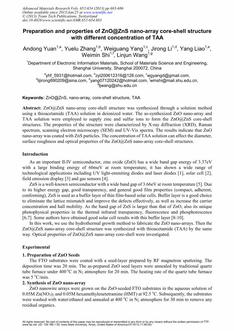
Figure 1 shows XRD patterns of ZnO@ZnS nano-array core-shell structure with 3 different concentration of TAA aqueous solution. The peaks at 31.6 °, 34.3 ° and 36.1 ° can be well indexed to the (100), (002) and (101) plane of hexagonal ZnO with lattice constants ɑ = 3.249Å and c = 5.208Å, in good agreement with the standard PDF data (JCPDS Card No. 36-1451). The diffraction peak at 28.8 ° corresponds to the (111) plane of the ZnS phase (JCPDS Card No. 05-0566, ɑ = 5.406Å). Although the intensity is not very strong, we still can preliminary find that the ZnS phase exists in the ZnO@ZnS nano-array core-shell structure. The nano-sized ZnS phase could be synthesized through a reaction of the TAA and the ZnO in this experiment.
Fig.1. XRD patterns of ZnO@ZnS nano-array core-shell structure with different TAA concentration
2. Raman spectra
Figure 2 shows the corresponding Raman spectra of these three different concentrations of TAA aqueous solution, which give us further conclusions. We have observed two strong peaks centered at 575 and 1150 cm-1 for ZnO nano-arrays, which can be attributed to the A1[longitudinal optical (LO)] and A1 (2LO) phonon modes, respectively [11], indicating that the ZnO nano-arrays are of fine quality. In addition to the A1 (LO) and A1 (2LO) phono modes of ZnO, there are three other Raman peaks in the ZnO@ZnS nano-array core-shell structure synthesized after sulfidation. The Raman peaks located at 350, 699, and 1045 cm-1 correspond well to the first-, second-, and third- order LO phono modes in
684 Advances in Materials and Materials Processing
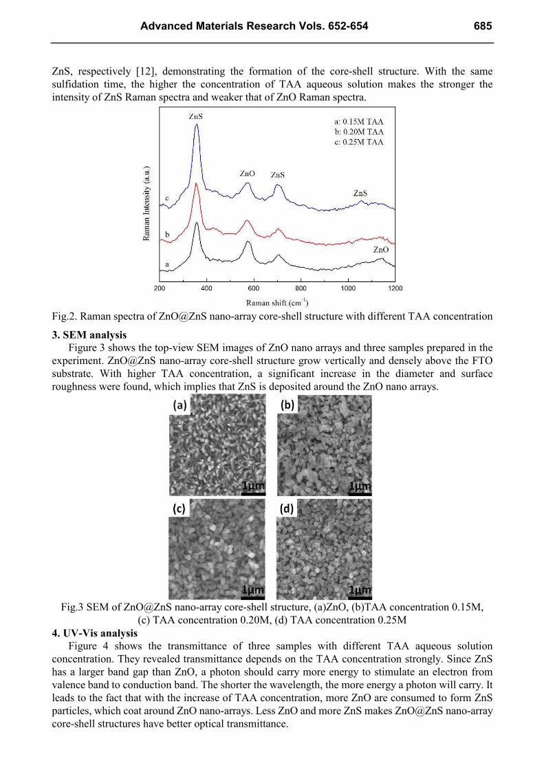
ZnS, respectively [12], demonstrating the formation of the core-shell structure. With the same sulfidation time, the higher the concentration of TAA aqueous solution makes the stronger the intensity of ZnS Raman spectra and weaker that of ZnO Raman spectra.
Fig.2. Raman spectra of ZnO@ZnS nano-array core-shell structure with different TAA concentration
3. SEM analysis
Figure 3 shows the top-view SEM images of ZnO nano arrays and three samples prepared in the experiment. ZnO@ZnS nano-array core-shell structure grow vertically and densely above the FTO substrate. With higher TAA concentration, a significant increase in the diameter and surface roughness were found, which implies that ZnS is deposited around the ZnO nano arrays.
Fig.3 SEM of ZnO@ZnS nano-array core-shell structure, (a)ZnO, (b)TAA concentration 0.15M,
(c) TAA concentration 0.20M, (d) TAA concentration 0.25M 4. UV-Vis analysis
Figure 4 shows the transmittance of three samples with different TAA aqueous solution concentration. They revealed transmittance depends on the TAA concentration strongly. Since ZnS has a larger band gap than ZnO, a photon should carry more energy to stimulate an electron from valence band to conduction band. The shorter the wavelength, the more energy a photon will carry. It leads to the fact that with the increase of TAA concentration, more ZnO are consumed to form ZnS particles, which coat around ZnO nano-arrays. Less ZnO and more ZnS makes ZnO@ZnS nano-array core-shell structures have better optical transmittance.
Advanced Materials Research Vols. 652-654 685
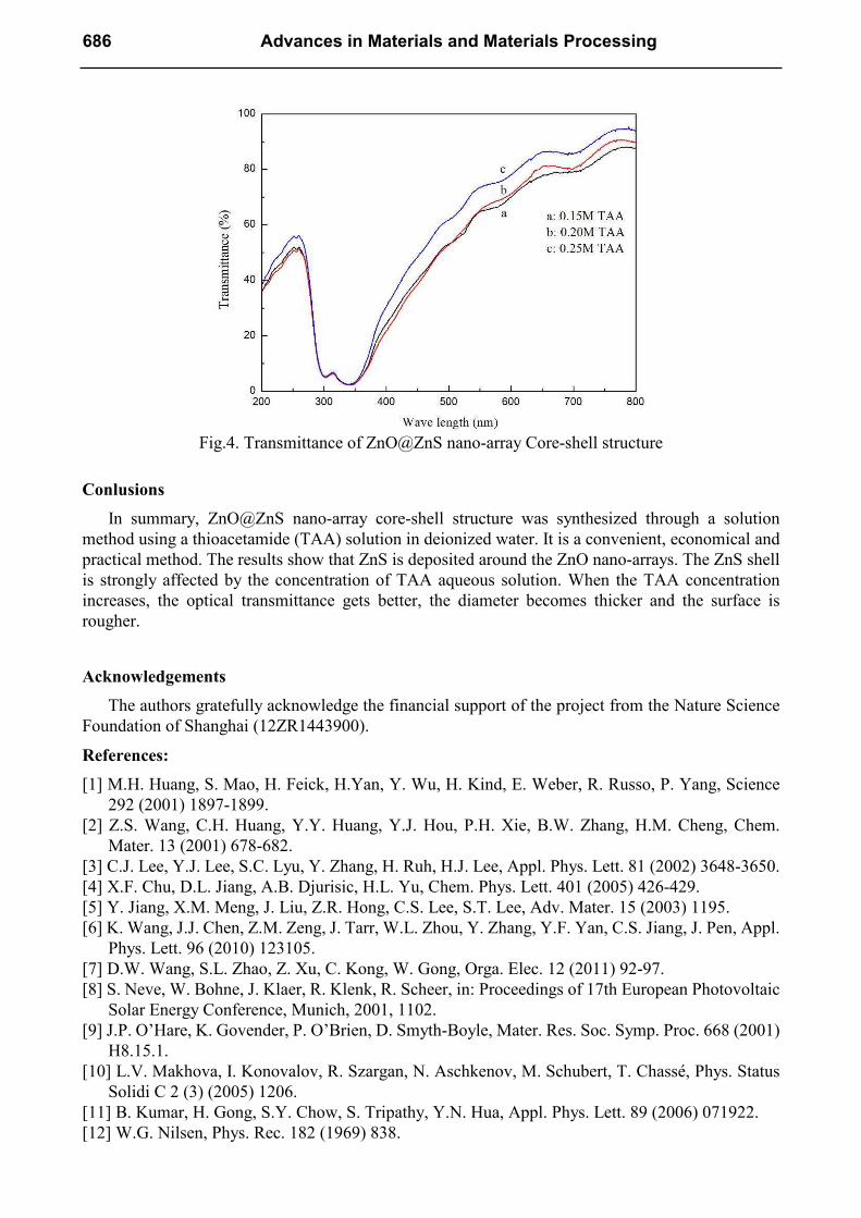
Fig.4. Transmittance of ZnO@ZnS nano-array Core-shell structure
Conlusions
In summary, ZnO@ZnS nano-array core-shell structure was synthesized through a solution method using a thioacetamide (TAA) solution in deionized water. It is a convenient, economical and practical method. The results show that ZnS is deposited around the ZnO nano-arrays. The ZnS shell is strongly affected by the concentration of TAA aqueous solution. When the TAA concentration increases, the optical transmittance gets better, the diameter becomes thicker and the surface is rougher.
Acknowledgements
The authors gratefully acknowledge the financial support of the project from the Nature Science Foundation of Shanghai (12ZR1443900).
References:
[1] M.H. Huang, S. Mao, H. Feick, H.Yan, Y. Wu, H. Kind, E. Weber, R. Russo, P. Yang, Science 292 (2001) 1897-1899.
[2] Z.S. Wang, C.H. Huang, Y.Y. Huang, Y.J. Hou, P.H. Xie, B.W. Zhang, H.M. Cheng, Chem. Mater. 13 (2001) 678-682.
[3] C.J. Lee, Y.J. Lee, S.C. Lyu, Y. Zhang, H. Ruh, H.J. Lee, Appl. Phys. Lett. 81 (2002) 3648-3650. [4] X.F. Chu, D.L. Jiang, A.B. Djurisic, H.L. Yu, Chem. Phys. Lett. 401 (2005) 426-429. [5] Y. Jiang, X.M. Meng, J. Liu, Z.R. Hong, C.S. Lee, S.T. Lee, Adv. Mater. 15 (2003) 1195. [6] K. Wang, J.J. Chen, Z.M. Zeng, J. Tarr, W.L. Zhou, Y. Zhang, Y.F. Yan, C.S. Jiang, J. Pen, Appl.
Phys. Lett. 96 (2010) 123105. [7] D.W. Wang, S.L. Zhao, Z. Xu, C. Kong, W. Gong, Orga. Elec. 12 (2011) 92-97. [8] S. Neve, W. Bohne, J. Klaer, R. Klenk, R. Scheer, in: Proceedings of 17th European Photovoltaic
Solar Energy Conference, Munich, 2001, 1102. [9] J.P. O’Hare, K. Govender, P. O’Brien, D. Smyth-Boyle, Mater. Res. Soc. Symp. Proc. 668 (2001)
H8.15.1. [10] L.V. Makhova, I. Konovalov, R. Szargan, N. Aschkenov, M. Schubert, T. Chassé, Phys. Status
Solidi C 2 (3) (2005) 1206. [11] B. Kumar, H. Gong, S.Y. Chow, S. Tripathy, Y.N. Hua, Appl. Phys. Lett. 89 (2006) 071922. [12] W.G. Nilsen, Phys. Rec. 182 (1969) 838.
686 Advances in Materials and Materials Processing

Advances in Materials and Materials Processing 10.4028/www.scientific.net/AMR.652-654 Preparation and Properties of ZnO@ZnS Nano-Array Core-Shell Structure with Different
Concentration of TAA 10.4028/www.scientific.net/AMR.652-654.683


![Investigation of chemical bath deposition of ZnO thin films using …lc/Khallaf-4.pdf · 2010. 1. 6. · CdO [5,6], ZnS [7,8], ZnSe [9,10] and ZnO [11–20]. Several complexing agents](https://img.pdfslide.us/doc/110x75/60837f3a233ad83fad582cf5/investigation-of-chemical-bath-deposition-of-zno-thin-films-using-lckhallaf-4pdf.jpg)