Embed Size (px)
Citation preview
Technical Report Documentation Page 1. Report No. FHWA/TX-05/9-1520-P1
2. Government Accession No.
3. Recipient's Catalog No. 5. Report Date January 2005
4. Title and Subtitle PRELIMINARY QUALITY CONTROL/QUALITY ASSURANCE STANDARDS (CRITERIA) FOR INSPECTION AND TESTING OF FRP BARS
6. Performing Organization Code
7. Author(s) David Trejo, Francisco Aguiñiga, Ray W. James, and Peter B. Keating
8. Performing Organization Report No. Product 9-1520-P1 10. Work Unit No. (TRAIS)
9. Performing Organization Name and Address Texas Transportation Institute The Texas A&M University System College Station, Texas 77843-3135
11. Contract or Grant No. Project 9-1520 13. Type of Report and Period Covered Product
12. Sponsoring Agency Name and Address Texas Department of Transportation Research and Technology Implementation Office P. O. Box 5080 Austin, Texas 78763-5080
14. Sponsoring Agency Code
15. Supplementary Notes Project performed in cooperation with the Texas Department of Transportation and the Federal Highway Administration. Project Title: FRP Reinforcing Bars in Bridge Decks URL: http://tti.tamu.edu/documents/9-1520-P1.pdf 16. Abstract
Fiber-reinforced polymers (FRP) are being increasingly used in the construction industry. One application is to use FRP bars as reinforcement in concrete. Glass fiber-reinforced polymer (GFRP) bars have been the focus of recent research because in corrosive environments they do not produce expansive corrosion products and the resulting concrete cracking and spalling associated with conventional steel reinforcement. Also, the initial cost of GFRP bars is lower than carbon FRP bars. During this research project, one challenge encountered with the use of GFRP bars was that limited guidance was available on what quality control and quality assurance parameters should be inspected. Also during this research project, standard testing procedures to assess key characteristics were only available in the Japanese literature. Thus, one objective of this research project was to provide guidance for the user on the following issues: 1) how to assess and test GFRP bars characteristics; and 2) how to assure that certain minimum quality levels have been achieved. This report provides this information. 17. Key Words GFRP, Strength, Quality Control, Tensile Strength, Tensile Modulus of Elasticity, Bond, Shear, Bent Bar Capacity, Time-Dependent Characteristics, Coefficient of Thermal Expansion, Visual Inspection
18. Distribution Statement No restrictions. This document is available to the public through NTIS: National Technical Information Service Springfield, Virginia 22161 http://www.ntis.gov
19. Security Classif.(of this report) Unclassified
20. Security Classif.(of this page) Unclassified
21. No. of Pages 24
22. Price
Form DOT F 1700.7 (8-72) Reproduction of completed page authorized

PRELIMINARY QUALITY CONTROL/QUALITY ASSURANCE STANDARDS (CRITERIA) FOR INSPECTION AND TESTING OF FRP BARS
by
David Trejo, PhD Associate Professor and Associate Researcher
Texas A&M University and Texas Transportation Institute
Francisco Aguiñiga, PhD Assistant Professor
Texas A&M University Kingsville
Ray W. James, PhD Associate Professor and Manager, Highway Structures Program
Texas A&M University and Texas Transportation Institute
and
Peter B. Keating, PhD Associate Professor and Associate Researcher
Texas A&M University and Texas Transportation Institute
Product 9-1520-P1 Project Number 9-1520
Project Title: FRP Reinforcing Bars in Bridge Decks
Performed in Cooperation with the Texas Department of Transportation
and the Federal Highway Administration
January 2005
TEXAS TRANSPORTATION INSTITUTE The Texas A&M University System College Station, Texas 77843-3135

v
DISCLAIMER
The contents of this report reflect the views of the authors who are responsible for the facts and the accuracy of the data presented herein. The contents do not necessarily reflect the official view or policies of the Federal Highway Administration (FHWA) or the Texas Department of Transportation (TxDOT). This report does not constitute a standard, specification, or regulation. The researcher in charge of the project was Dr. David Trejo.
vi
ACKNOWLEDGMENTS This project was performed in cooperation with the Federal Highway Administration and the Texas Department of Transportation. This report was performed by Drs. David Trejo, Francisco Aguiñiga, Ray W. James, and Peter B. Keating. Financial support for the research was provided by the Federal Highway Administration, Texas Department of Transportation, and the Texas Transportation Institute. The authors wish to express their gratitude to: Project Coordinator:
Ronald E. Koester, P.E., TxDOT, Waco District Project Director:
Timothy E. Bradberry, P.E., TxDOT, Bridge Division Project Advisors:
Don Harley, P.E., Federal Highway Administration Mary Lou Ralls, P.E., Retired State Bridge Engineer, TxDOT Joe Chappell, P.E., TxDOT, Amarillo District Mark Bloschock, P.E., TxDOT, Bridge Division Kevin Pruski, P.E., TxDOT, Bridge Division Robert Sarcinella, TxDOT, Construction Division Paul McDad, TxDOT, Construction Division
vii
Table of Contents
PAGE
LIST OF FIGURES viii
I. INTRODUCTION 1
II. TEST METHOD AND MINIMUM MATERIAL CHARACTERISTICS 3
Visual Assessment 4
Cross-section Characteristics 5
Tensile Strength 6
Tensile Modulus of Elasticity 8
Bond and development Length 9
Shear Strength 9
Bent Bar Capacity 10
Time-dependent Characteristics 10
Coefficient of Thermal Expansion 11
III. SUMMARY 13
REFERENCES 15
viii
LIST OF FIGURES
FIGURE PAGE
Figure 1. Improper storage of GFRP bars at construction site. 4
Figure 2. Burnt GFRP bar. 5
Figure 3. Consolidating concrete around GFRP bars. 5
Figure 4. Cross-sections of different GFRP bars (Trejo et al. 2003). 6
1
I. INTRODUCTION
Although serious concerns still exist with the use of glass fiber-reinforced
polymer (GFRP) reinforcing bars for concrete reinforcement, many researchers are
continuing to investigate their performance with the objective of improving their
performance. In past cases where GFRP bars have been used as reinforcement, limited
guidance has been available on how to assess the mechanical and physical characteristics
of these materials to ensure some minimum performance. At the start of this research
limited guidance on test procedures was available. The research team reviewed the
literature and in cases followed methods from the literature. In some cases the research
team used test methods from the Japanese Society of Civil Engineering’s (JSCE)
Recommendation for Design and Construction of Concrete Structures Using Continuous
Fiber Reinforcing Materials (1997). However, significant progress on testing of GFRP
products has occurred over the last several years, especially within the American
Concrete Institutes (ACI) Committee 440, Fiber Reinforced Polymer Reinforcement.
This report is presented so that important characteristics of GFRP reinforcement
can be assessed to achieve some minimum level of quality. When test methods from
ACI or JSCE are recommended, the reader will be directed to these corresponding
documents for test information. It should be noted that in this document quality
assurance is defined as a set of activities designed to ensure that the development and/or
manufacturing process is adequate to ensure a material will meet their objectives
(durability and serviceability). Of course, quality assurance is also performed in the
manufacturing process but this report will not address quality assurance techniques used
by the manufacturers. However, GFRP bars should be manufactured to assure some
minimal serviceability and life expectancy. These qualities should be at least the
minimum qualities of steel reinforcement. Quality control is defined here as a set of
activities designed to evaluate a product, in this case, GFRP bars, for minimum levels of
quality. This is accomplished with testing.
2
A quality control program is dependent on many factors. A quality control
program for one agency may include evaluating all characteristics using the test
procedures reported herein. Quality control programs for other agencies may include
only select tests. It is the responsibility of the user to select a proper quality control
program.
This report includes information on testing and minimum values (when
available) for tensile strength, tensile modulus of elasticity, bond properties, shear
strength, bent bar capacity, time-dependent characteristics, coefficient of thermal
expansion, and residual strength and absorption of GFRP bars exposed to high pH
environments. Methods for visually assessing GFRP bars and determining the cross-
sectional characteristics of GFRP bars are also included. The bent bar capacity, some
time-dependent characteristics, and the coefficient of thermal expansion tests were not
performed as part of this project. However, a brief explanation of these tests is included
for completeness.
3
II. TEST METHODS AND MINIMUM MATERIAL
CHARACTERISTICS
Using GFRP reinforcing bars in infrastructure systems is relatively new.
Challenges with implementing the use of this material has included the lack of
standardized test procedures, quality control programs, and quality assurance. The
following tests can be used to implement a quality control program. However, it should
be noted that GFRP products continually change with the hopes of improving the
properties and characteristics. As GFRP products are produced with different materials,
the engineering properties and performance of these materials will change. As such, the
following presentations are guidelines. The user must use good engineering judgment in
implementing a quality control program.
As noted in ACI 440.1R-03 (2003), Guide for the Design and Construction of
Concrete Reinforced with FRP Bars, quality control of GFRP bars should be performed
by lot testing, either by the manufacturer or an independent, qualified third party.
Manufacturers should provide the user with production run traceability. The ACI 440
(2003) document recommends evaluating the tensile strength, tensile modulus of
elasticity, ultimate strain, fatigue strength, bond strength, coefficient of thermal
expansion, and durability in alkaline environments. Additional testing should include
static fatigue, a comprehensive visual assessment before placing the surrounding
concrete, determining the cross-sectional characteristics of the bar, and when bent bars
are used, evaluating the strength of these bent GFRP bars. Although ACI 440 (2003)
recommends testing product “before or after any change in manufacturing process,
procedure, or materials,” unless the manufacturer has shown that the product
characteristics do not change with time within a defined manufacturing process,
procedure, or set of materials, product testing should be performed at shorter intervals.
4
Visual Assessment
Results from this research project indicate that damage to the surface of GFRP
bars can lead to significant reductions in durability and longer-term strength. However,
limited guidelines are available for visually assessing GFRP bars. The objective of this
section is to provide the user with general information on visually inspecting GFRP
reinforcing bars. Because it is imperative that these bars be properly handled,
transported, stored, and placed to minimize damage and maximize performance, a brief
overview of handling, storing, and placing GFRP reinforcing bars is provided.
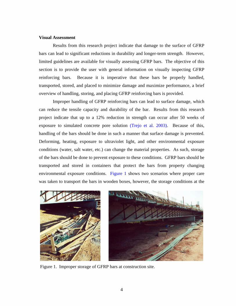
Improper handling of GFRP reinforcing bars can lead to surface damage, which
can reduce the tensile capacity and durability of the bar. Results from this research
project indicate that up to a 12% reduction in strength can occur after 50 weeks of
exposure to simulated concrete pore solution (Trejo et al. 2003). Because of this,
handling of the bars should be done in such a manner that surface damage is prevented.
Deforming, heating, exposure to ultraviolet light, and other environmental exposure
conditions (water, salt water, etc.) can change the material properties. As such, storage
of the bars should be done to prevent exposure to these conditions. GFRP bars should be
transported and stored in containers that protect the bars from property changing
environmental exposure conditions. Figure 1 shows two scenarios where proper care
was taken to transport the bars in wooden boxes, however, the storage conditions at the
Figure 1. Improper storage of GFRP bars at construction site.
5
construction site were not appropriate. Storage of GFRP bars at the construction site
should be such that exposure conditions do not change the properties of the bars.
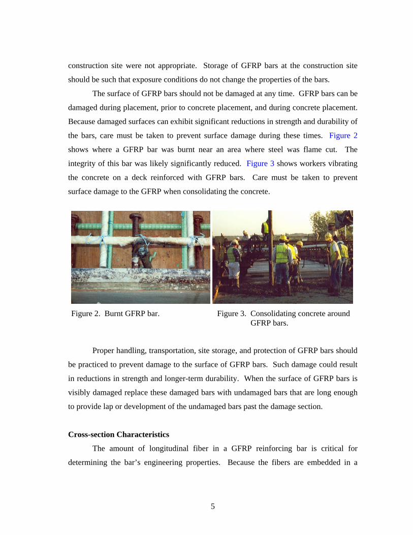
The surface of GFRP bars should not be damaged at any time. GFRP bars can be
damaged during placement, prior to concrete placement, and during concrete placement.
Because damaged surfaces can exhibit significant reductions in strength and durability of
the bars, care must be taken to prevent surface damage during these times. Figure 2
shows where a GFRP bar was burnt near an area where steel was flame cut. The
integrity of this bar was likely significantly reduced. Figure 3 shows workers vibrating
the concrete on a deck reinforced with GFRP bars. Care must be taken to prevent
surface damage to the GFRP when consolidating the concrete.
Proper handling, transportation, site storage, and protection of GFRP bars should
be practiced to prevent damage to the surface of GFRP bars. Such damage could result
in reductions in strength and longer-term durability. When the surface of GFRP bars is
visibly damaged replace these damaged bars with undamaged bars that are long enough
to provide lap or development of the undamaged bars past the damage section.
Cross-section Characteristics
The amount of longitudinal fiber in a GFRP reinforcing bar is critical for
determining the bar’s engineering properties. Because the fibers are embedded in a
Figure 2. Burnt GFRP bar. Figure 3. Consolidating concrete around GFRP bars.
6
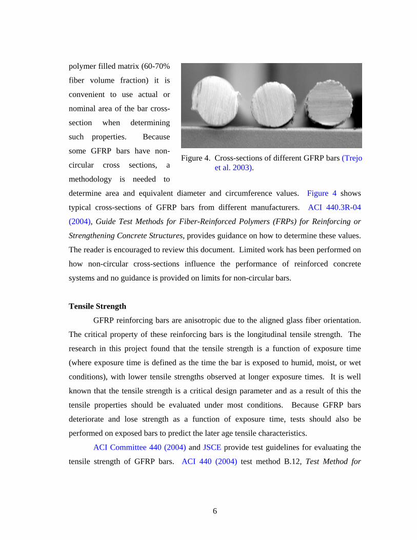
polymer filled matrix (60-70%
fiber volume fraction) it is
convenient to use actual or
nominal area of the bar cross-
section when determining
such properties. Because
some GFRP bars have non-
circular cross sections, a
methodology is needed to
determine area and equivalent diameter and circumference values. Figure 4 shows
typical cross-sections of GFRP bars from different manufacturers. ACI 440.3R-04
(2004), Guide Test Methods for Fiber-Reinforced Polymers (FRPs) for Reinforcing or
Strengthening Concrete Structures, provides guidance on how to determine these values.
The reader is encouraged to review this document. Limited work has been performed on
how non-circular cross-sections influence the performance of reinforced concrete
systems and no guidance is provided on limits for non-circular bars.
Tensile Strength
GFRP reinforcing bars are anisotropic due to the aligned glass fiber orientation.
The critical property of these reinforcing bars is the longitudinal tensile strength. The
research in this project found that the tensile strength is a function of exposure time
(where exposure time is defined as the time the bar is exposed to humid, moist, or wet
conditions), with lower tensile strengths observed at longer exposure times. It is well
known that the tensile strength is a critical design parameter and as a result of this the
tensile properties should be evaluated under most conditions. Because GFRP bars
deteriorate and lose strength as a function of exposure time, tests should also be
performed on exposed bars to predict the later age tensile characteristics.
ACI Committee 440 (2004) and JSCE provide test guidelines for evaluating the
tensile strength of GFRP bars. ACI 440 (2004) test method B.12, Test Method for
Figure 4. Cross-sections of different GFRP bars (Trejo
et al. 2003).
7
Longitudinal Properties of FRP Bars, provide detailed procedures for evaluating the
tensile strength of unexposed GFRP bars. ACI 440 (2004) test method B.6, Accelerated
Test Method for Alkali Resistance of FRP Bars, and JSCE (1997) E 538-1995, Test
Method for Alkali Resistance of Continuous Fiber Reinforcing Materials, provide
guidelines for evaluating the change in tensile strength as a function of exposure time.
The reader is encouraged to review these documents for specifics on these tests.
ACI 440 (2003) recommends that tensile properties of FRP bars should be
obtained from the manufacturer and recommends that this value be a guaranteed tensile
strength, f fu* . This guaranteed tensile strength, f fu
* , is defined as being the mean value
of the tensile strength of a set of bars minus three times the standard deviation. The
manufacturer must be careful that the sample size (typically greater than 25 to 30
samples) is sufficiently large and representative of the entire production run. If this is
not the case, more detailed analyses should be performed. In any case, the manufacturer
should report the number of samples tested and the sampling method used to select test
samples.
Because the tensile strength of GFRP bars in concrete deteriorate with exposure
time it is necessary to determine the rate of deterioration of these bars. As already noted,
ACI and JSCE provide test methods for exposing the bars. The reader is encouraged to
review these standards. The bars can be exposed to simulated concrete pore solution or
directly to the concrete. Much debate exists on the applicability of exposing GFRP to
simulated concrete pore solution. Exposing GFRP bars to simulated concrete pore
solution likely better represents the deterioration rate of saturated concrete. The rate of
loss of tensile strength is likely lower for unsaturated conditions. However, more
research is needed to determine this. Testing under stressed conditions will likely better
represent the actual rate of strength loss. As such, at this time, it is recommended that
the lower values of tensile strengths of stressed samples be used to estimate the strength
reduction of GFRP bars. It is also recommended that testing of these bars be performed
well beyond the 6 months recommended in the ACI 440 (2004) document.
8
Once these data are obtained the service life of the structure can be determined
by fitting a best fit line through the lower data points and determining the time in which
the tensile strength of the deteriorating bars is equivalent to an environmental reduction
factor, CE (0.8 for GFRP reinforced concrete not exposed to earth and weather and 0.7
for GFRP reinforced concrete exposed to earth and weather), multiplied by the
guaranteed tensile strength. Results from testing in this project indicate that the residual
tensile strength of unstressed GFRP bars exposed to simulated solution will be lower
than the product of the environmental reduction factor for weather exposure and the
guaranteed tensile strength after approximately 7 years. It is believed that had testing
been performed in stressed conditions this time would have been significantly shorter.
Of course, stressed samples embedded in unsaturated concrete conditions would likely
be longer than the stressed conditions in simulated concrete pore solution.
Tensile Modulus of Elasticity
One of the challenges associated with the use of GFRP bars is the low modulus
of elasticity of this product. Lower modulus of elasticity values present challenges in the
design process and can lead to more and/or larger cracks in a GFRP reinforced structure.
However, significant work has been performed to develop design guidelines with GFRP
reinforcement. For information on testing GFRP reinforcing bars for tensile modulus of
elasticity the reader is directed to ACI 440 (2004) test method B.2, Test Method for
Longitudinal Tensile Properties of FRP Bars, and JSCE-E 531-1995 (JSCE 1997), Test
Method for Tensile Properties of Continuous Fiber Reinforcing Materials. Information
on design using GFRP reinforcement that exhibits low modulus of elasticity values
(compared to steel) can be found in ACI 440 (2003) and JSCE (1997) documents.
ACI 440 (2003) reports a range of modulus of elasticity values for GFRP bars
from 5.1x10⁶ to 7.4x10⁶
psi. All mean values of modulus of elasticity for the unexposed
reinforcement tested in this research project fell within this range. After exposure,
several mean values were closer to the minimum value of this range and below the
5.8x10⁶ psi minimum specified by the TxDOT’s special specification for GFRP bar
9
reinforced concrete slab. Several results were also lower than the ACI minimum.
Further research is needed to investigate the change in modulus of elasticity as a
function of time exposed to a concrete environment.
Bond and Development Length
The bond characteristics of GFRP bars are influenced by the following: the
manufacturing process for the bar, the surface conditions of the bar, the environmental
exposure conditions and time of exposure, the test method, and other factors. ACI 440
(2003) states that the bond capacity of GFRP bars is independent of concrete strength
when adequate cover is provided. The reader is directed to ACI 440 (2004) test B.3,
Test Method for Bond Strength of FRP Bars by Pullout Testing, and JSCE-E 540-1995
(1997), Test Method for Bond Strength of Continuous Fiber Reinforcing Materials by
Pullout Testing, for test procedures to evaluate the bond of GFRP. ACI 440 (2003)
recommends that bond values be obtained from the manufacturer but also provides a
conservative estimate of the basic development length of FRP bars controlled by pullout
failure as follows:
lbf =db ⋅CE ⋅ f fu
*
2700 (1)
where db is the bar diameter in inches and CE and f fu* have already been defined. The
results of this research indicate that the ACI 440 equation is adequate. JSCE (1997)
proposes an alternative and more complex equation for development length. However,
because the ACI 440 (2003) equation seems to be adequate, discussions on the JSCE
method for determining development length will not be discussed here. If the reader
would like more information on the JSCE method for determining development length
the reader is directed to section 10.5.3 of the JSCE (1997) document.
Shear Strength
The shear strength of GFRP reinforcement could be used for determining the
contribution of longitudinal bars in terms of dowel action. However, because limited
10
work has been performed for this application, neither ACI (2003) nor JSCE (1997)
provide recommendations for this. Results from the research in this project indicated
that all bar types had mean shear strength values that exceeded 21,000 psi. In most
cases, the shear strength decreased with exposure time. More research is needed to
determine the contribution of longitudinal GFRP reinforcement in terms of dowel action.
Bent Bar Capacity
This research project did not evaluate the capacity of bent GFRP bars. All GFRP
bars tested in this research project were made of thermoset resins and bending of these
bars was not possible due to the nature of thermoset resins used of these bars. However,
it is well established that bars bent prior to curing of the thermoset resin exhibit
significant reductions in capacity. JSCE (1997) provides no guidance on testing bent
GFRP bars. ACI 440 (2004) test method B.5, Test Method for Bars Strength of FRP
Bent Bars and Stirrups at Bent Locations, provides guidelines for testing bent bars.
Because no research was performed in the research project on this topic the reader is
encouraged to review the ACI 440 documents (2003, 2004) to determine testing methods
and minimum strength requirements.
Time-Dependent Characteristics
Two types of fatigue characteristics will be described here: static fatigue (also
known as creep rupture) and conventional fatigue due to cyclic loading. When fiber-
reinforced polymer bars are subjected to constant load over time these bars can suddenly
fail due to static fatigue. ACI 440 (2003) states that glass fibers, and thus GFRP bars,
are most susceptible to static fatigue. This ACI document also notes that little work has
been performed on GFRP reinforcing bars. However, this document references an
investigation by Seki et al. (1997) that show an extrapolated 45% reduction in tensile
strength after 50 years. More research is needed in this area and users must consider this
reduction in property during design.
11
ACI 440 (2003) also notes that cyclic tensile fatigue can reduce the static tensile
capacity of GFRP bars by 10% per decade of logarithmic time. This indicates that a
60% reduction in the static tensile strength of GFRP bars could occur after 1 million
cycles. Although this research did not investigate the fatigues characteristics of the
GFRP bars evaluated in this project, GFRP-reinforced concrete sections were evaluated
under cyclic loading conditions. With the exception of one test, the reduction in beam
capacity for most beams was less than 13% after at least 1.9 million cycles. However,
the deflection of the beams under cyclic loading did increase with increased cyclic
loading.
ACI 440 (ACI 2004) method B.7, Test Method for Tensile Fatigue of FRP Bars,
and JSCE-E 535-1995 (JSCE 1997), Test Method for Tensile Fatigue of Continuous
Fiber Reinforcing Materials, may be used to assess the fatigue characteristics of GFRP
bars. However, because only limited research has been performed in the area of fatigue
of GFRP reinforcement bars, no recommendations can be provided at this time on
minimum quality control values. The user should be aware that significant reductions in
GFRP reinforcement strength could occur under static and cyclic loading conditions.
ACI 440 (2003) limits the creep rupture stress for GFRP bars to 20% of the guaranteed
tensile strength. According to TxDOT design notes the GFRP bars of the deck of the
Sierrita de la Cruz Creek Bridge have a calculated maximum service stress of less than
15 percent and a sustained service stress of less than 5 percent of the specified
guaranteed tensile strength of the bars.
Coefficient of Thermal Expansion
One advantage of GFRP reinforcing bars is that these bars do not exhibit the
classical cracking and spalling caused by the corrosion of metallic materials. Although
glass fibers do corrode and lose strength (see ACI 440 [2003] section 3.3.2), the
corrosion products are non-expansive. Although these corrosion products are non-
expansive, volume changes in GFRP bars can occur. Gentry (1999) reported that the
transverse coefficient of thermal expansion of FRP bars ranged from 4 to 9 times that of
12
concrete. For GFRP-reinforced structures directly exposed to the environment, this
thermal expansion could result in cracking of the concrete cover. JSCE (1997) E 536-
1995, Test Method for Coefficient of Thermal Expansion of Continuous Fiber
Reinforcing Materials by Thermo-mechanical Analysis, provides guidelines on how to
evaluate this material characteristic. ACI 440 (2004) provides no guidance on
evaluating this parameter.
Testing performed as part of this project did not include standardized test
procedures. However, the research indicated that cracking did not occur when the
temperature of GFRP reinforced samples was raised to greater than 50 oF above the
temperature of the concrete samples when fabricated. Also, field observations of the
Sierrita de la Cruz Bridge, which was partially constructed with GFRP bars, did not
show signs of thermal cracking above the GFRP bars. Although low concrete covers
and low concrete strengths could lead to thermal mismatch cracking of the concrete
cover under extreme conditions, cracking caused by thermal mismatch of GFRP
reinforcing bars with adequate concrete cover (> 1 inch) and strength (> 5900 psi)
should not be an issue. Other conditions not evaluated in this research need further
evaluation.
13
III. SUMMARY
Although GFRP bars for concrete reinforcement have been manufactured from
some time, they have recently been experiencing more frequent use in infrastructure
systems. This report identified some key characteristics of GFRP bars that should be
evaluated prior to their use in reinforced concrete infrastructure systems. The reader
should be aware that limited long-term information is available on the use of GFRP bars
for reinforcement in concrete and the reader should be cautious in developing and
implementing a quality control program. The suite of tests and proposed quality control
program described above should provide the minimum needed to evaluate the
characteristics of GFRP reinforcing bars.

15
REFERENCES
ACI 440.1R-03 “Guide for the Design and Construction of Concrete Reinforced with
FRP Bars” American Concrete Institute, Farmington Hills, Michigan, USA, May 2003,
42 pp.
ACI 440.3R-04 (2004), Guide Test Methods for Fiber-Reinforced Polymers (FRPs) for
Reinforcing or Strengthening Concrete Structures, American Concrete Institute,
Committee 440, Detroit, Michigan.
Japanese Society of Civil Engineering (1997), Recommendation for Design and
Construction of Concrete Structures Using Continuous Fiber Reinforcing Materials,
Concrete Engineering Series 23, Ed. A. Machida, JSCE, Tokyo, Japan.
Seki, H., Kekijima, K., and Konno, T., (1997), “Test Method on Creep of Continuous
Fiber Reinforcing Materials,” Proceedings of the Third International Symposium on
Non-Metallic (FRP) Reinforcement for Concrete Structures (FRPRCS-3), Sapporo,
Japan, Vol. 2, pp. 195-202.
Trejo, D., Aguiñiga, F., Yuan, R.L., James, R.W., and Keating, P.B., (2003)
Characterization of Design Parameters for Fiber Reinforced Polymer Composite
Reinforced Concrete Systems


![GFRP [Resin Infusion]](https://img.pdfslide.us/doc/110x75/546e67d4af795971298b5642/gfrp-resin-infusion.jpg)