Embed Size (px)
Citation preview
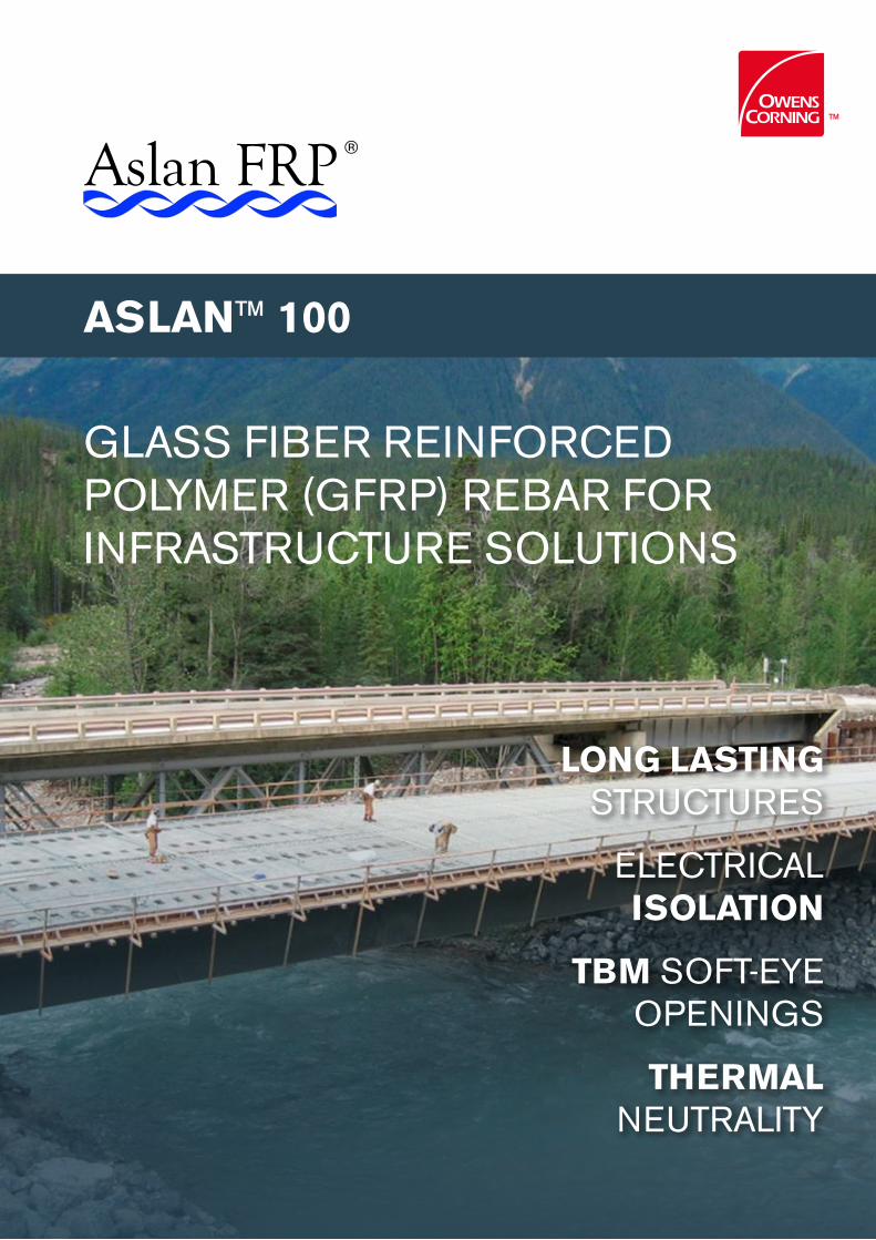
GLASS FIBER REINFORCED POLYMER (GFRP) REBAR FOR INFRASTRUCTURE SOLUTIONS
LONG LASTING STRUCTURES
ELECTRICAL ISOLATION
TBM SOFT-EYE OPENINGS
THERMAL NEUTRALITY
ASLAN™ 100
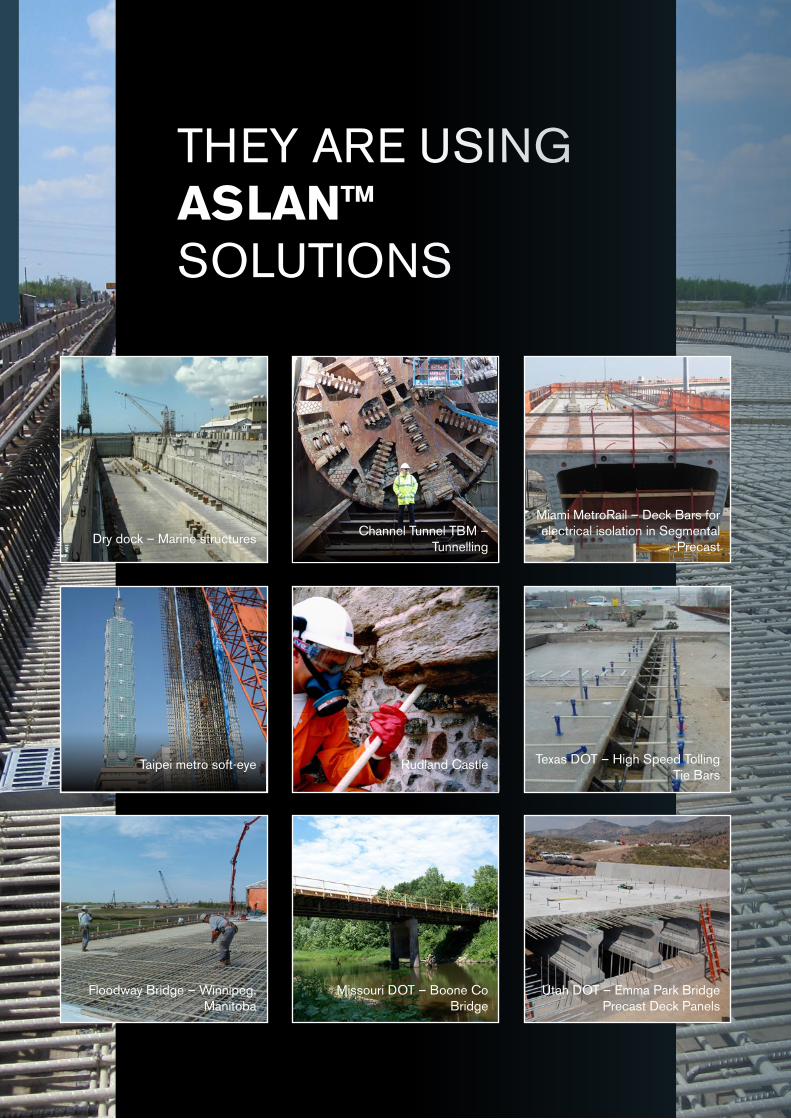
THEY ARE USING ASLAN™ SOLUTIONS
Taipei metro soft-eye Rudland Castle Texas DOT – High Speed Tolling Tie Bars
Floodway Bridge – Winnipeg, Manitoba
Missouri DOT – Boone Co Bridge
Dry dock – Marine structures
Miami MetroRail – Deck Bars for electrical isolation in Segmental
PrecastChannel Tunnel TBM –
Tunnelling
Utah DOT – Emma Park Bridge Precast Deck Panels
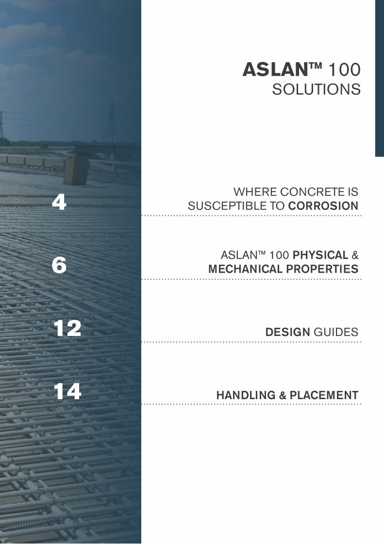
ASLAN™ 100 SOLUTIONS
4WHERE CONCRETE IS
SUSCEPTIBLE TO CORROSION
6ASLAN™ 100 PHYSICAL &
MECHANICAL PROPERTIES
12 DESIGN GUIDES
14 HANDLING & PLACEMENT
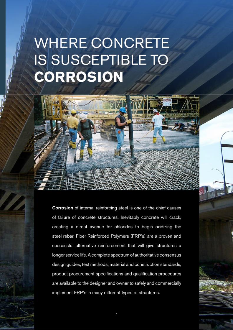
WHERE CONCRETE IS SUSCEPTIBLE TO CORROSION
Corrosion of internal reinforcing steel is one of the chief causes
of failure of concrete structures. Inevitably concrete will crack,
creating a direct avenue for chlorides to begin oxidizing the
steel rebar. Fiber Reinforced Polymers (FRP’s) are a proven and
successful alternative reinforcement that will give structures a
longer service life. A complete spectrum of authoritative consensus
design guides, test methods, material and construction standards,
product procurement specifications and qualification procedures
are available to the designer and owner to safely and commercially
implement FRP’s in many different types of structures.
4
CONCRETE EXPOSED TO DE-ICING CHLORIDES
Bridge Decks & Railings
Median Barriers
Approach Slabs
Salt Storage Facilities
Continuously Reinforced Concrete Paving
Precast Elements : Manhole Covers, Culverts, Rail
Grade & Crossings, Full Depth Deck Panels, etc.
CONCRETE EXPOSED TO MARINE CHLORIDES
Sea Walls, Wharfs, Quays & Dry Docks
Coastal Construction exposed to Salt Fog
Desalinization intakes
Port Aprons
CONCRETE EXPOSED TO HIGH VOLTAGE & ELEC-TROMAGNETIC FIELDS
Light & Heavy Rail 3rd Rail Isolation
Hospital MRI Areas
High Voltage Substations
Cable Ducts & Banks
Aluminum Smelters & Steel Mills
Radio Frequency Sensitive Areas
High Speed Highway Tolling Zones
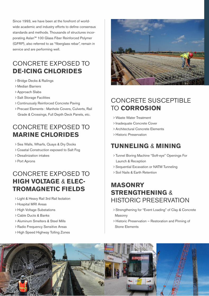
Since 1993, we have been at the forefront of world-
wide academic and industry efforts to define consensus
standards and methods. Thousands of structures incor-
porating Aslan™ 100 Glass Fiber Reinforced Polymer
(GFRP), also referred to as “fiberglass rebar”, remain in
service and are performing well.
CONCRETE SUSCEPTIBLE TO CORROSION
Waste Water Treatment
Inadequate Concrete Cover
Architectural Concrete Elements
Historic Preservation
TUNNELING & MINING Tunnel Boring Machine “Soft-eye” Openings For
Launch & Reception
Sequential Excavation or NATM Tunneling
Soil Nails & Earth Retention
MASONRY STRENGTHENING & HISTORIC PRESERVATION
Strengthening for “Event Loading” of Clay & Concrete
Masonry
Historic Preservation – Restoration and Pinning of
Stone Elements

ASLAN™ 100 PHYSICAL & MECHANICAL PROPERTIES
6
BENEFITS Impervious to Chloride Ion and low pH chemical attack
Tensile strengths greater than steel
1/4 the weight of steel rebar
Transparent to magnetic fields and radio frequencies
Electrically non-conductive
Thermally non-conductive
7
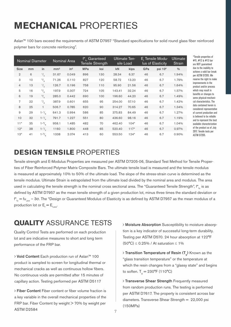
MECHANICAL PROPERTIES
Nominal Diameter Nominal Areaf*fu Garanteed
Tensile StrengthUltimate Ten-
sile LoadEf Tensile Modu-lus of Elasticity
Ultimate Strain
Size mm in mm² in² MPa ksi kN kips GPa psi 106 %
2 6 1/4 31.67 0.049 896 130 28.34 6.37 46 6.7 1.94%
3 10 3/8 71.26 0.110 827 120 58.72 13.20 46 6.7 1.79%
4 13 1/2 126.7 0.196 758 110 95.90 21.56 46 6.7 1.64%
5 16 5/8 197.9 0.307 724 105 143.41 32.24 46 6.7 1.57%
6 19 3/4 285.0 0.442 690 100 196.60 44.20 46 6.7 1.49%
7 22 7/8 387.9 0.601 655 95 254.00 57.10 46 6.7 1.42%
8 25 1 506.7 0.785 620 90 314.27 70.65 46 6.7 1.34%
9 29 1-1/8 641.3 0.994 586 85 375.83 84.49 46 6.7 1.27%
10 32 1-1/4 791.7 1.227 551 80 436.60 98.16 46 6.7 1.19%
11* 35 1-3/8 958.1 1.485 482 70 462.40 104* 46 6.7 1.04%
12* 38 1-1/2 1160 1.800 448 65 520.40 117* 46 6.7 0.97%
13* 41 1-5/8 1338 2.074 413 60 553.50 124* 46 6.7 0.90%
DESIGN TENSILE PROPERTIESTensile strength and E-Modulus Properties are measured per ASTM D7205-06, Standard Test Method for Tensile Proper-
ties of Fiber Reinforced Polymer Matrix Composite Bars. The ultimate tensile load is measured and the tensile modulus
is measured at approximately 10% to 50% of the ultimate load. The slope of the stress-strain curve is determined as the
tensile modulus. Ultimate Strain is extrapolated from the ultimate load divided by the nominal area and modulus. The area
used in calculating the tensile strength is the nominal cross sectional area. The “Guaranteed Tensile Strength”, f*fu is as
defined by ASTM D7957 as the mean tensile strength of a given production lot, minus three times the standard deviation or
f*fu = fu,ave – 3σ. The “Design or Guaranteed Modulus of Elasticity is as defined by ASTM D7957 as the mean modulus of a
production lot or Ef = Ef,ave.
Aslan™ 100 bars exceed the requirements of ASTM D7957 “Standard specifications for solid round glass fiber reinforced
polymer bars for concrete reinforcing”.
Moisture Absorption Susceptibility to moisture absorp-
tion is a key indicator of successful long-term durability.
Testing per ASTM D570. 24 hour absorption at 122°F
(50°C) ≤ 0.25% / At saturation ≤ 1%
Transition Temperature of Resin (Tg) Known as the
“glass transition temperature” or the temperature at
which the resin changes from a “glassy state” and begins
to soften. Tg = 230°F (110°C)
Transverse Shear Strength Frequently measured
from random production runs. The testing is performed
per ASTM D7617. The property is consistent across bar
diameters. Transverse Shear Strength = 22,000 psi
(150MPa)
*Tensile properties of #11, #12 & #13 bar are NOT guaranteed due to the inability to achieve a valid bar break per ASTM D7205. We reserve the right to make improvements in the product and/or process which may result in benefits or changes to some physical-mechani-cal characteristics. The data contained herein is considered representative of current production and is believed to be reliable and to represent the best available characterization of the product as of July 2017. Tensile tests per ASTM D7205.
QUALITY ASSURANCE TESTSQuality Control Tests are performed on each production
lot and are indicative measures to short and long term
performance of the FRP bar.
Void Content Each production run of Aslan™ 100
product is sampled to screen for longitudinal thermal or
mechanical cracks as well as continuous hollow fibers.
No continuous voids are permitted after 15 minutes of
capillary action. Testing performed per ASTM D5117
Fiber Content Fiber content or fiber volume fraction is
a key variable in the overall mechanical properties of the
FRP bar. Fiber Content by weight > 70% by weight per
ASTM D2584
8
CHARACTERISTIC PROPERTIES
BOND
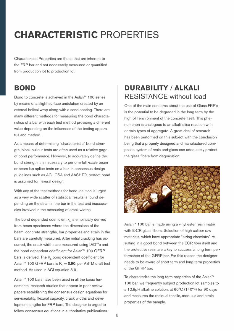
One of the main concerns about the use of Glass FRP’s
is the potential to be degraded in the long term by the
high pH environment of the concrete itself. This phe-
nomenon is analogous to an alkali silica reaction with
certain types of aggregate. A great deal of research
has been performed on this subject with the conclusion
being that a properly designed and manufactured com-
posite system of resin and glass can adequately protect
the glass fibers from degradation.
Aslan™ 100 bar is made using a vinyl ester resin matrix
with E-CR glass fibers. Selection of high caliber raw
materials, which have appropriate “sizing chemistry” re-
sulting in a good bond between the ECR fiber itself and
the protective resin are a key to successful long term per-
formance of the GFRP bar. For this reason the designer
needs to be aware of short term and long-term properties
of the GFRP bar.
To characterize the long term properties of the Aslan™
100 bar, we frequently subject production lot samples to
a 12.8pH alkaline solution, at 60°C (140°F) for 90 days
and measures the residual tensile, modulus and strain
properties of the sample.
DURABILITY / ALKALI RESISTANCE without loadBond to concrete is achieved in the Aslan™ 100 series
by means of a slight surface undulation created by an
external helical wrap along with a sand coating. There are
many different methods for measuring the bond characte-
ristics of a bar with each test method providing a different
value depending on the influences of the testing appara-
tus and method.
As a means of determining ”characteristic” bond stren-
gth, block pullout tests are often used as a relative gage
of bond performance. However, to accurately define the
bond strength it is necessary to perform full -scale beam
or beam lap splice tests on a bar. In consensus design
guidelines such as ACI, CSA and AASHTO, perfect bond
is assumed for flexural design.
With any of the test methods for bond, caution is urged
as a very wide scatter of statistical results is found de-
pending on the strain in the bar in the test and inaccura-
cies involved in the measuring of crack widths.
The bond depended coefficient kb is empirically derived
from beam specimens where the dimensions of the
beam, concrete strengths, bar properties and strain in the
bars are carefully measured. After initial cracking has oc-
curred, the crack widths are measured using LVDT’s and
the bond dependent coefficient for Aslan™ 100 GFRP
bars is derived. The Kb bond dependent coefficient for
Aslan™ 100 GFRP bars is Kb = 0.90, per ASTM draft test
method. As used in ACI equation 8-9.
Aslan™ 100 bars have been used in all the basic fun-
damental research studies that appear in peer review
papers establishing the consensus design equations for
serviceability, flexural capacity, crack widths and deve-
lopment lengths for FRP bars. The designer is urged to
follow consensus equations in authoritative publications.
Characteristic Properties are those that are inherent to
the FRP bar and not necessarily measured or quantified
from production lot to production lot.
Aslan™ 100 bars achieve residual tensile strength re-
tention in excess of 80% making them a “D1” durability
according to CSA Standard S-807.
Tensile E-modulus properties are typically not affected by
the alkaline bath at elevated temperatures.
Subjecting the GFRP bars to an aqueous, high pH
solution at elevated temperatures is not intended to be a
perfectly accurate measure of the long term residual pro-
perties of the GFRP bar, rather its purpose is to differen-
tiate high caliber GFRP bars from lesser quality ones.
The unlimited supply of free ions in the purely aqueous
elevated pH solution are much more harmful than actual
field conditions. This conclusion is drawn from a series of
tests performed on GFRP bars extracted from service in
several structures across Canada by the ISIS research
network that reveals NO DEGREDATION of GFRP bars
after being in service for eight to ten years. At this time,
there is no consensus as to what would be an accurate
service life prediction model for the use of GFRP bars.
Links to the complete ISIS findings are available at the
Aslan™ FRP web site.
As compared to properties at ambient conditions, tempe-
ratures at low as -40°F (-40°C) have less than 5% effect
on the tensile strength of the bar
TENSILE STRENGTH AT COLD TEMPERATURE
The Coefficient of Thermal Expansion or CTE of the
GFRP bars is an inherent characteristic property and
if sufficient concrete cover of two bar diameters is
used, it is not an important design consideration. This
is because there is not enough radial force to cause
reflective concrete cracking if adequate concrete confi-
nement is present. These findings are elaborated in the
work of Aiello, Focacci & Nanni in ACI Materials Journal,
Vol. 98 No. 4, July-Aug 2001, pp. 332-339 “Effects of
COEFFICIENT OF THERMAL EXPANSION
Thermal Loads on Concrete Cover of FRP Reinforced
Elements: Theoretical and Experiential Analysis.” Further,
the transverse CTE is a non-linear property and affected
by the helical wrap on the Aslan™ 100 bar. Differing labs
achieve a wide scatter in measured CTE results depen-
ding on the test method and set-up.
CREEP RUPTURE / SUSTAINED LOADSFRP bars subjected to a constant load over time can
suddenly fail after a time period called the endurance
time. The endurance time is greatly affected by the envi-
ronmental conditions such as high temperature, alkalinity,
wet and dry cycles, freezing and thawing cycles. As the
percentage of sustained tensile stress to short-term
strength of the bar increases, the endurance time de-
creases. For this reason, the design limits on GFRP bars
in consensus standards limit sustained loads on GFRP
bars to very low levels of utilization. The design professio-
nal should use the appropriate consensus guideline for
creep rupture stress limits.
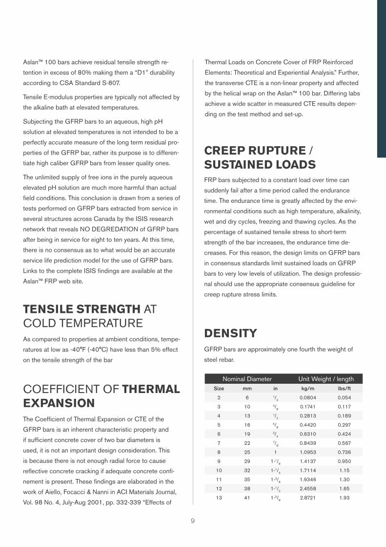
DENSITYGFRP bars are approximately one fourth the weight of
steel rebar.
Nominal Diameter Unit Weight / lengthSize mm in kg/m lbs/ft
2 6 1/4 0.0804 0.054
3 10 3/8 0.1741 0.117
4 13 1/2 0.2813 0.189
5 16 5/8 0.4420 0.297
6 19 3/4 0.6310 0.424
7 22 7/8 0.8439 0.567
8 25 1 1.0953 0.736
9 29 1-1/8 1.4137 0.950
10 32 1-1/4 1.7114 1.15
11 35 1-3/8 1.9346 1.30
12 38 1-1/2 2.4558 1.65
13 41 1-5/8 2.8721 1.93
9
10
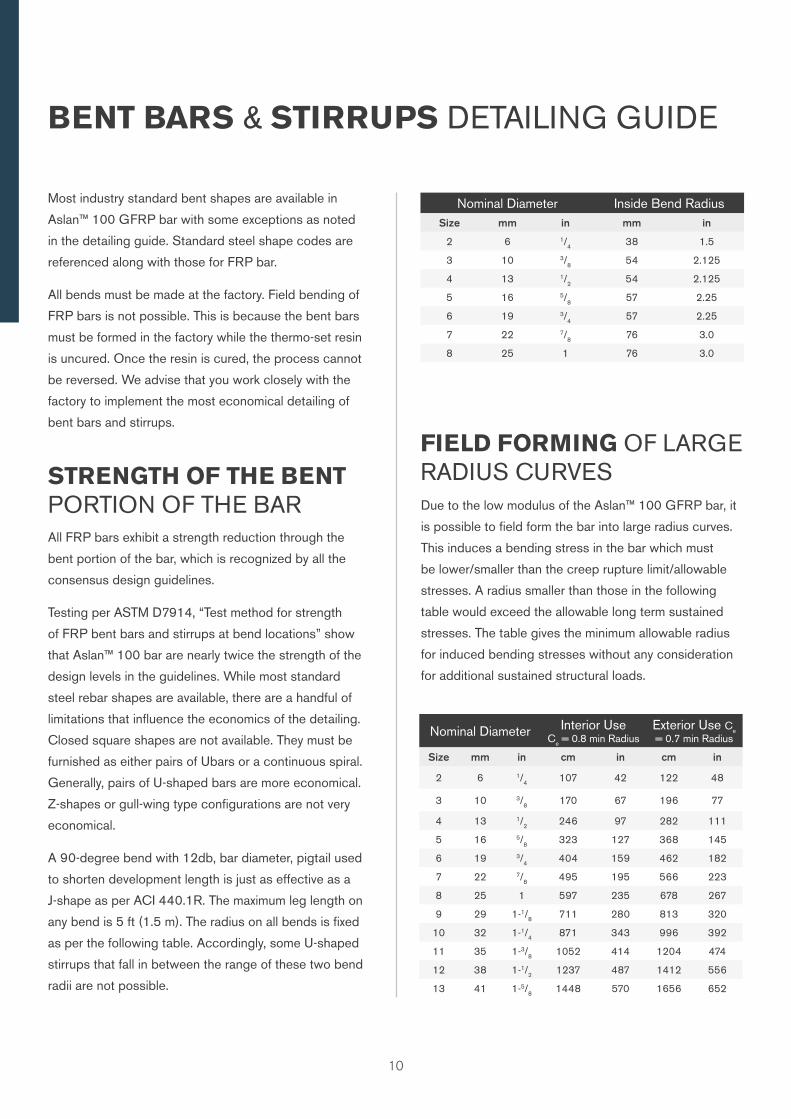
BENT BARS & STIRRUPS DETAILING GUIDE
Most industry standard bent shapes are available in
Aslan™ 100 GFRP bar with some exceptions as noted
in the detailing guide. Standard steel shape codes are
referenced along with those for FRP bar.
All bends must be made at the factory. Field bending of
FRP bars is not possible. This is because the bent bars
must be formed in the factory while the thermo-set resin
is uncured. Once the resin is cured, the process cannot
be reversed. We advise that you work closely with the
factory to implement the most economical detailing of
bent bars and stirrups.
Due to the low modulus of the Aslan™ 100 GFRP bar, it
is possible to field form the bar into large radius curves.
This induces a bending stress in the bar which must
be lower/smaller than the creep rupture limit/allowable
stresses. A radius smaller than those in the following
table would exceed the allowable long term sustained
stresses. The table gives the minimum allowable radius
for induced bending stresses without any consideration
for additional sustained structural loads.
FIELD FORMING OF LARGE RADIUS CURVES
Nominal Diameter Interior Use Ce = 0.8 min Radius
Exterior Use Ce = 0.7 min Radius
Size mm in cm in cm in
2 6 1/4 107 42 122 48
3 10 3/8 170 67 196 77
4 13 1/2 246 97 282 111
5 16 5/8 323 127 368 145
6 19 3/4 404 159 462 182
7 22 7/8 495 195 566 223
8 25 1 597 235 678 267
9 29 1-1/8 711 280 813 320
10 32 1-1/4 871 343 996 392
11 35 1-3/8 1052 414 1204 474
12 38 1-1/2 1237 487 1412 556
13 41 1-5/8 1448 570 1656 652
All FRP bars exhibit a strength reduction through the
bent portion of the bar, which is recognized by all the
consensus design guidelines.
Testing per ASTM D7914, “Test method for strength
of FRP bent bars and stirrups at bend locations” show
that Aslan™ 100 bar are nearly twice the strength of the
design levels in the guidelines. While most standard
steel rebar shapes are available, there are a handful of
limitations that influence the economics of the detailing.
Closed square shapes are not available. They must be
furnished as either pairs of Ubars or a continuous spiral.
Generally, pairs of U-shaped bars are more economical.
Z-shapes or gull-wing type configurations are not very
economical.
A 90-degree bend with 12db, bar diameter, pigtail used
to shorten development length is just as effective as a
J-shape as per ACI 440.1R. The maximum leg length on
any bend is 5 ft (1.5 m). The radius on all bends is fixed
as per the following table. Accordingly, some U-shaped
stirrups that fall in between the range of these two bend
radii are not possible.
STRENGTH OF THE BENT PORTION OF THE BAR
Nominal Diameter Inside Bend RadiusSize mm in mm in
2 6 1/4 38 1.5
3 10 3/8 54 2.125
4 13 1/2 54 2.125
5 16 5/8 57 2.25
6 19 3/4 57 2.25
7 22 7/8 76 3.0
8 25 1 76 3.0
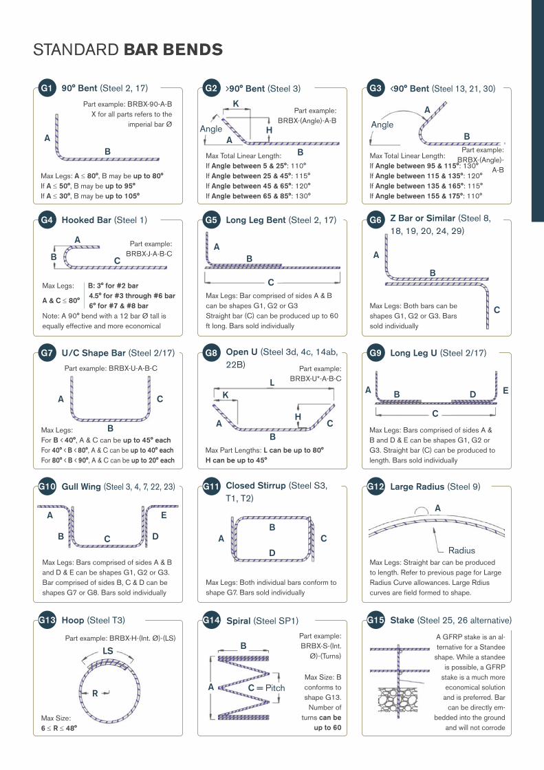
STANDARD BAR BENDS
Part example: BRBX-90-A-BX for all parts refers to the
imperial bar Ø
90° Bent (Steel 2, 17)
Max Legs: A ≤ 80°, B may be up to 80°If A ≤ 50°, B may be up to 95°If A ≤ 30°, B may be up to 105°
AB
G1
Part example: BRBX-(Angle)-A-B
90° Bent (Steel 3)
Max Total Linear Length:If Angle between 5 & 25°: 110°If Angle between 25 & 45°: 115°If Angle between 45 & 65°: 120°If Angle between 65 & 85°: 130°
G2
AHAngle
B
K
Part example: BRBX-(Angle)-
A-B
90° Bent (Steel 13, 21, 30)
Max Total Linear Length:If Angle between 95 & 115°: 130°If Angle between 115 & 135°: 120°If Angle between 135 & 165°: 115°If Angle between 155 & 175°: 110°
G3
A
AngleB
Part example: BRBX-J-A-B-C
Hooked Bar (Steel 1)G4 Long Leg Bent (Steel 2, 17)
Max Legs: Bar comprised of sides A & B can be shapes G1, G2 or G3Straight bar (C) can be produced up to 60 ft long. Bars sold individually
G5
AB
C
Z Bar or Similar (Steel 8, 18, 19, 20, 24, 29)
Max Legs: Both bars can be shapes G1, G2 or G3. Bars sold individually
G6
Max Legs: B: 3° for #2 bar4.5° for #3 through #6 bar6° for #7 & #8 bar
Note: A 90° bend with a 12 bar Ø tall is equally effective and more economical
A & C ≤ 80°
A
B CA
B
C
Part example: BRBX-U-A-B-C
U/C Shape Bar (Steel 2/17)
Max Legs: For B 40°, A & C can be up to 45° eachFor 40° B 80°, A & C can be up to 40° eachFor 80° B 90°, A & C can be up to 20° each
G7 Open U (Steel 3d, 4c, 14ab, 22B) Part example:
BRBX-U*-A-B-C
Max Part Lengths: L can be up to 80°H can be up to 45°
G8 Long Leg U (Steel 2/17)
Max Legs: Bars comprised of sides A & B and D & E can be shapes G1, G2 or G3. Straight bar (C) can be produced to length. Bars sold individually
G9
A BA
B
C
AH
B
K
C
L
C
D E
Gull Wing (Steel 3, 4, 7, 22, 23)G10 Closed Stirrup (Steel S3, T1, T2)
Max Legs: Both individual bars conform to shape G7. Bars sold individually
G11 Large Radius (Steel 9)
Max Legs: Straight bar can be produced to length. Refer to previous page for Large Radius Curve allowances. Large Rdius curves are field formed to shape.
G12
Max Legs: Bars comprised of sides A & B and D & E can be shapes G1, G2 or G3. Bar comprised of sides B, C & D can be shapes G7 or G8. Bars sold individually
Part example: BRBX-H-(Int. Ø)-(LS)
Hoop (Steel T3)
Max Size: 6 ≤ R ≤ 48°
G13 Spiral (Steel SP1)
Part example: BRBX-S-(Int.
Ø)-(Turns)
Max Size: B conforms to shape G13.
Number of turns can be
up to 60
G14 Stake (Steel 25, 26 alternative)
A GFRP stake is an al-ternative for a Standee
shape. While a standee is possible, a GFRP
stake is a much more economical solution
and is preferred. Bar can be directly em-
bedded into the ground and will not corrode
G15
LS
R
A
Radius
A
B
C = Pitch
A
B C D
E
AB
D
C
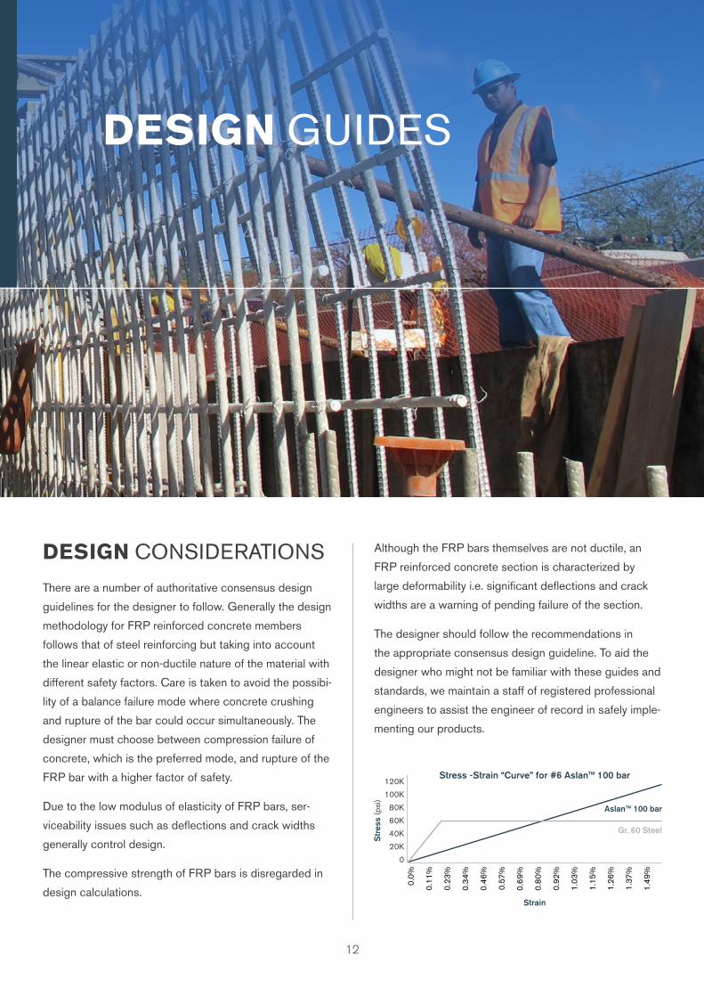
DESIGN GUIDES
12
DESIGN CONSIDERATIONS Although the FRP bars themselves are not ductile, an
FRP reinforced concrete section is characterized by
large deformability i.e. significant deflections and crack
widths are a warning of pending failure of the section.
The designer should follow the recommendations in
the appropriate consensus design guideline. To aid the
designer who might not be familiar with these guides and
standards, we maintain a staff of registered professional
engineers to assist the engineer of record in safely imple-
menting our products.
There are a number of authoritative consensus design
guidelines for the designer to follow. Generally the design
methodology for FRP reinforced concrete members
follows that of steel reinforcing but taking into account
the linear elastic or non-ductile nature of the material with
different safety factors. Care is taken to avoid the possibi-
lity of a balance failure mode where concrete crushing
and rupture of the bar could occur simultaneously. The
designer must choose between compression failure of
concrete, which is the preferred mode, and rupture of the
FRP bar with a higher factor of safety.
Due to the low modulus of elasticity of FRP bars, ser-
viceability issues such as deflections and crack widths
generally control design.
The compressive strength of FRP bars is disregarded in
design calculations.
120K
100K
80K
60K
40K
20K
0
0.0%
0.11
%
0.23
%
0.3
4%
0.4
6%
0.57
%
0.6
9%
0.8
0%
0.92
%
1.03
%
1.15
%
1.26
%
1.37
%
1.4
9%
Str
ess
(psi
)
Strain
Stress -Strain “Curve” for #6 Aslan™ 100 bar
Gr. 60 Steel
Aslan™ 100 bar
13
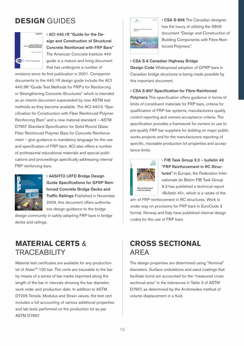
DESIGN GUIDES
ACI 440.1R “Guide for the De-
sign and Construction of Structural
Concrete Reinforced with FRP Bars”
The American Concrete Institute 440
guide is a mature and living document
that has undergone a number of
revisions since its first publication in 2001. Companion
documents to the 440.1R design guide include the ACI
440.3R “Guide Test Methods for FRP’s for Reinforcing
or Strengthening Concrete Structures” which is intended
as an interim document superseded by new ASTM test
methods as they become available. The ACI 440.5 “Spe-
cification for Construction with Fiber Reinforced Polymer
Reinforcing Bars” and a new material standard – ASTM
D7957 Standard Specification for Solid Round Glass
Fiber Reinforced Polymer Bars for Concrete Reinforce-
ment – give guidance in mandatory language for the use
and specification of FRP bars. ACI also offers a number
of professional educational materials and special publi-
cations and proceedings specifically addressing internal
FRP reinforcing bars.
AASHTO LRFD Bridge Design
Guide Specifications for GFRP Rein-
forced Concrete Bridge Decks and
Traffic Railings Published in November
2009, this document offers authorita-
tive design guidance to the bridge
design community in safely adopting FRP bars in bridge
decks and railings.
CSA S-806 The Canadian designer
has the luxury of utilizing the S806
document “Design and Construction of
Building Components with Fibre-Rein-
forced Polymers”.
CSA S-6 Canadian Highway Bridge
Design Code Widespread adoption of GFRP bars in
Canadian bridge structures is being made possible by
this important document.
CSA S-807 Specification for Fibre-Reinforced
Polymers This specification offers guidance in terms of
limits of constituent materials for FRP bars, criteria for
qualification of FRP bar systems, manufacturers quality
control reporting and owners acceptance criteria. The
specification provides a framework for owners to use to
pre-qualify FRP bar suppliers for bidding on major public
works projects and for the manufacturers reporting of
specific, traceable production lot properties and accep-
tance limits.
FIB Task Group 9.3 – bulletin 40
“FRP Reinforcement in RC Struc-
tures” In Europe, the Federation Inter-
nationale du Beton FIB Task Group
9.3 has published a technical report
«Bulletin 40», which is a «state of the
art» of FRP reinforcement in RC structures. Work is
under way on provisions for FRP bars in EuroCode 2
format. Norway and Italy have published internal design
codes for the use of FRP bars.
Material test certifcates are available for any production
lot of Aslan™ 100 bar. The certs are traceable to the bar
by means of a series of bar marks imprinted along the
length of the bar in intervals showing the bar diameter,
work order and production date. In addition to ASTM
D7205 Tensile, Modulus and Strain values, the test cert
includes a full accounting of various additional properties
and lab tests performed on the production lot as par
ASTM D7957.
MATERIAL CERTS & TRACEABILITY
The design properties are determined using “Nominal”
diameters. Surface undulations and sand coatings that
facilitate bond are accounted for the “measured cross
sectional area” in the tolerances in Table 3 of ASTM
D7957, as determined by the Archimedes method of
volume displacement in a fluid.
CROSS SECTIONAL AREA
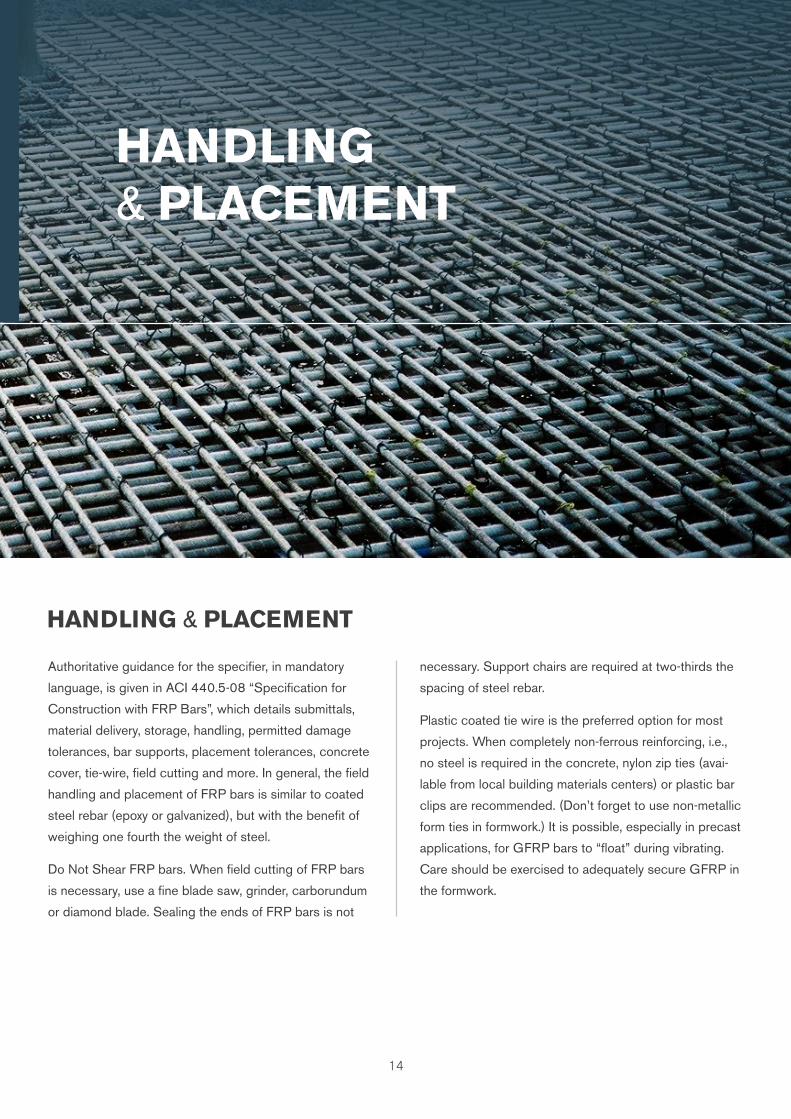
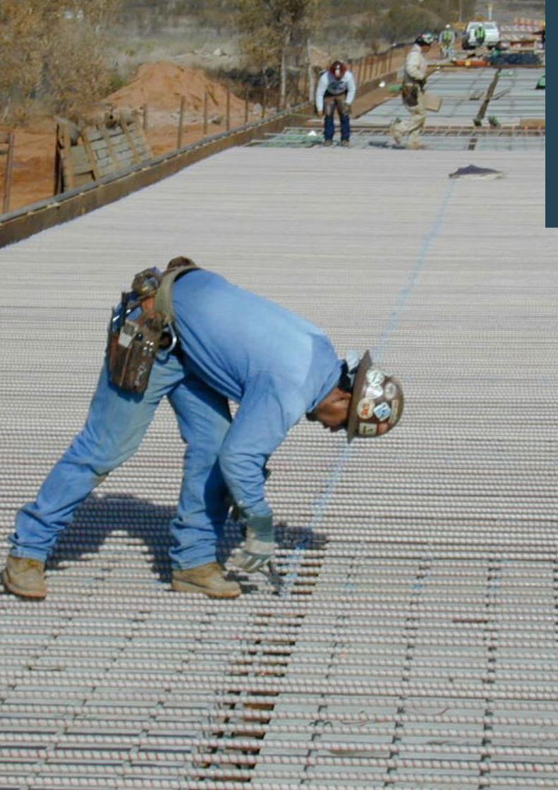
HANDLING & PLACEMENT
14
HANDLING & PLACEMENT
Authoritative guidance for the specifier, in mandatory
language, is given in ACI 440.5-08 “Specification for
Construction with FRP Bars”, which details submittals,
material delivery, storage, handling, permitted damage
tolerances, bar supports, placement tolerances, concrete
cover, tie-wire, field cutting and more. In general, the field
handling and placement of FRP bars is similar to coated
steel rebar (epoxy or galvanized), but with the benefit of
weighing one fourth the weight of steel.
Do Not Shear FRP bars. When field cutting of FRP bars
is necessary, use a fine blade saw, grinder, carborundum
or diamond blade. Sealing the ends of FRP bars is not
necessary. Support chairs are required at two-thirds the
spacing of steel rebar.
Plastic coated tie wire is the preferred option for most
projects. When completely non-ferrous reinforcing, i.e.,
no steel is required in the concrete, nylon zip ties (avai-
lable from local building materials centers) or plastic bar
clips are recommended. (Don’t forget to use non-metallic
form ties in formwork.) It is possible, especially in precast
applications, for GFRP bars to “float” during vibrating.
Care should be exercised to adequately secure GFRP in
the formwork.
Owens Corning Infrastructure Solutions, LLCOne Owens Corning ParkwayToledo, OH 43659+1 402 646 62621-800-GET-PINK™
This information and data contained herein is offered solely as a guide in the selection of product. We believe this information to be reliable, but do not guarantee its applicability to the user’s process or assume any responsibility or liability arising out of its use or performance. The user agrees to be responsible for thoroughly testing any application of the product to determine its suitability. Because of numerous factors affecting results, we make no warranty of any kind, express or implied, including those of merchantability and fitness for a particular purpose. Statements in this publication shall not be construed as representations or warranties or as inducements to infringe any patent or violate any law, safety code or insurance regulation. We reserve the right to modify this document without prior notice. © 2017 Owens Corning. All Rights Reserved.Pub. 10022286. Aslan 100 GFRP rebars brochure_ww_10-2017_Rev1_EN. October 2017
Cove
r and
bac
k pic
. © A
dobe
Sto
ck
™