Embed Size (px)
Citation preview

1
PRELIMINARY NUMERICAL INVESTIGATION ON THE SEISMIC
RESIDUAL CAPACITY OF REINFORCED CONCRETE
PLASTIC HINGES
Alberto CUEVAS1 Umut AKGUZEL2 Joško OŽBOLT3 and Stefano PAMPANIN4
ABSTRACT
This paper presents the results of experimental and numerical investigations on well-designed
reinforced concrete beam-column joints. Nonlinear finite element (FE) analyses were performed, and
experimental results of a two-thirds scale beam-column joint with the same characteristics subject to
quasi-static displacement-controlled lateral loading were used to validate the numerical model.
Subsequently, as part of a wider research project aiming at investigating the seismic residual capacity
of reinforced concrete frames, parametric analyses under monotonic loading were performed targeting
at investigating and understanding qualitatively and quantitatively the effect of parameters such as
bond deterioration, steel and concrete material properties, as well as the amount of longitudinal
reinforcement, on the cracking pattern and nonlinear behaviour of reinforced concrete plastic hinges.
INTRODUCTION
According to capacity design principles developed since the 1960s-1970s, structures are
designed to withstand major earthquakes by developing inelastic action and energy dissipation in
concentrated regions referred to as plastic hinges. This in turn, and almost inevitably when using
traditional monolithic connections, leads to structural damage, often over the irreparability threshold.
The aftermath of the Christchurch earthquakes sequence in 2010-2011 has highlighted the crucial need
to move towards a damage control philosophy and low-damage technologies whilst improving
assessment and repairing techniques for more traditionally designed plastic hinges (Pampanin, 2012).
Despite the availability and recent development of seismic assessment and rehabilitation
guidelines, they are mainly focused to the evaluation of the vulnerability and improvement of the
seismic performance of existing buildings designed prior to capacity design principles. Very little
information and assistance is provided in assessing the residual capacity of damaged buildings, yet
relatively well designed according to modern seismic codes, which leading to extensive post-
earthquake demolitions due to the lack of knowledge on their residual capacity, in terms of number
and intensity of aftershocks the structure could withstand following a major earthquake and during its
remainder life-time. When considering the problem of residual capacity of typical plastic hinges, past
research has tended to primarily focus on bridge columns (Kunnath et al., 1997; Mander and Cheng,
1999), and specifically on the assessment of the low-cycle fatigue of the longitudinal reinforcement
(Mander et al., 1994; Abdalla et al., 2009; Haliweh et al., 2010), often based on the assumption that
1 PhD Candidate, University of Canterbury, Christchurch, New Zealand,
[email protected] 2 PhD, Senior Structural Engineer, Beca Ltd, Christchurch, New Zealand, [email protected] 3 Professor, Institute for Construction Materials, University of Stuttgart, Germany, [email protected] 4 Professor, University of Canterbury, Christchurch, New Zealand, [email protected]
2
the failure in a reinforced concrete element can be attributed to either the low-cycle fatigue of the
longitudinal reinforcing steel, the failure of the concrete due to either lack of confinement or the
fracture of the transverse hoop reinforcement, and/or the buckling of the longitudinal reinforcement in
compression. The latter two mechanisms can be easily avoided if sufficient transverse reinforcement is
provided (Mander and Cheng, 1999). However, as it has been observed after recent earthquakes, the
low cycle fatigue of the longitudinal reinforcement is only one part of the overall picture; there are
other factors such as bond deterioration between steel and concrete, the amount of longitudinal and
transverse reinforcement, as well as the characteristics of steel and concrete materials that strongly
influences the plastic hinge behaviour, its cracking pattern and therefore, its overall residual capacity.
As part of a wider research project aiming at investigating the seismic residual capacity of
reinforced concrete frames, this paper presents the results of an experimental and numerical
investigation on a modern (i.e., relatively well-designed according to post-1970s seismic codes)
reinforced concrete beam-to-column joint, targeting at identifying and understanding qualitatively and
quantitatively the effect of parameters such as bond deterioration, steel and concrete material
properties, as well as the amount of longitudinal reinforcement, on the cracking pattern and nonlinear
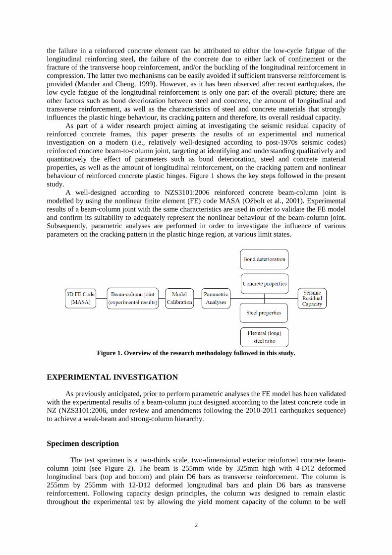
behaviour of reinforced concrete plastic hinges. Figure 1 shows the key steps followed in the present
study.
A well-designed according to NZS3101:2006 reinforced concrete beam-column joint is
modelled by using the nonlinear finite element (FE) code MASA (Ožbolt et al., 2001). Experimental
results of a beam-column joint with the same characteristics are used in order to validate the FE model
and confirm its suitability to adequately represent the nonlinear behaviour of the beam-column joint.
Subsequently, parametric analyses are performed in order to investigate the influence of various
parameters on the cracking pattern in the plastic hinge region, at various limit states.
Figure 1. Overview of the research methodology followed in this study.
EXPERIMENTAL INVESTIGATION
As previously anticipated, prior to perform parametric analyses the FE model has been validated
with the experimental results of a beam-column joint designed according to the latest concrete code in
NZ (NZS3101:2006, under review and amendments following the 2010-2011 earthquakes sequence)
to achieve a weak-beam and strong-column hierarchy.
Specimen description
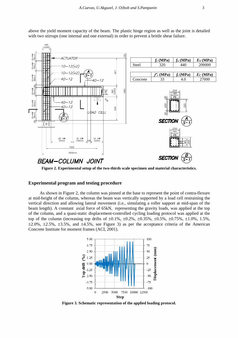
The test specimen is a two-thirds scale, two-dimensional exterior reinforced concrete beam-
column joint (see Figure 2). The beam is 255mm wide by 325mm high with 4-D12 deformed
longitudinal bars (top and bottom) and plain D6 bars as transverse reinforcement. The column is
255mm by 255mm with 12-D12 deformed longitudinal bars and plain D6 bars as transverse
reinforcement. Following capacity design principles, the column was designed to remain elastic
throughout the experimental test by allowing the yield moment capacity of the column to be well
A.Cuevas, U.Akguzel, J. Ožbolt and S.Pampanin 3
above the yield moment capacity of the beam. The plastic hinge region as well as the joint is detailed
with two stirrups (one internal and one external) in order to prevent a brittle shear failure.
Figure 2. Experimental setup of the two-thirds scale specimen and material characteristics.
Experimental program and testing procedure
As shown in Figure 2, the column was pinned at the base to represent the point of contra-flexure
at mid-height of the column, whereas the beam was vertically supported by a load cell restraining the
vertical direction and allowing lateral movement (i.e., simulating a roller support at mid-span of the
beam length). A constant axial force of 65kN, representing the gravity loads, was applied at the top
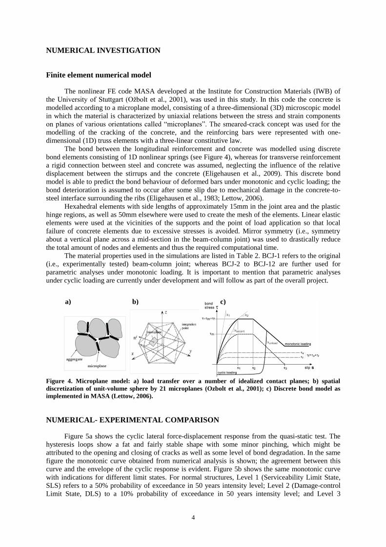
of the column, and a quasi-static displacement-controlled cycling loading protocol was applied at the
top of the column (increasing top drifts of 0.1%, 0.2%, 0.35%, 0.5%, 0.75%, 1.0%, 1.5%,
2.0%, 2.5%, 3.5%, and 4.5%, see Figure 3) as per the acceptance criteria of the American
Concrete Institute for moment frames (ACI, 2001).
Figure 3. Schematic representation of the applied loading protocol.
fy (MPa) fu (MPa) ES (MPa)
Steel 320 440 200000
f’c (MPa) ft (MPa) EC (MPa)
Concrete 33 4.0 27000
4
NUMERICAL INVESTIGATION
Finite element numerical model
The nonlinear FE code MASA developed at the Institute for Construction Materials (IWB) of
the University of Stuttgart (Ožbolt et al., 2001), was used in this study. In this code the concrete is
modelled according to a microplane model, consisting of a three-dimensional (3D) microscopic model
in which the material is characterized by uniaxial relations between the stress and strain components
on planes of various orientations called “microplanes”. The smeared-crack concept was used for the
modelling of the cracking of the concrete, and the reinforcing bars were represented with one-
dimensional (1D) truss elements with a three-linear constitutive law.
The bond between the longitudinal reinforcement and concrete was modelled using discrete
bond elements consisting of 1D nonlinear springs (see Figure 4), whereas for transverse reinforcement
a rigid connection between steel and concrete was assumed, neglecting the influence of the relative
displacement between the stirrups and the concrete (Eligehausen et al., 2009). This discrete bond
model is able to predict the bond behaviour of deformed bars under monotonic and cyclic loading; the
bond deterioration is assumed to occur after some slip due to mechanical damage in the concrete-to-
steel interface surrounding the ribs (Eligehausen et al., 1983; Lettow, 2006).
Hexahedral elements with side lengths of approximately 15mm in the joint area and the plastic
hinge regions, as well as 50mm elsewhere were used to create the mesh of the elements. Linear elastic
elements were used at the vicinities of the supports and the point of load application so that local
failure of concrete elements due to excessive stresses is avoided. Mirror symmetry (i.e., symmetry
about a vertical plane across a mid-section in the beam-column joint) was used to drastically reduce
the total amount of nodes and elements and thus the required computational time.
The material properties used in the simulations are listed in Table 2. BCJ-1 refers to the original
(i.e., experimentally tested) beam-column joint; whereas BCJ-2 to BCJ-12 are further used for
parametric analyses under monotonic loading. It is important to mention that parametric analyses
under cyclic loading are currently under development and will follow as part of the overall project.
Figure 4. Microplane model: a) load transfer over a number of idealized contact planes; b) spatial
discretization of unit-volume sphere by 21 microplanes (Ozbolt et al., 2001); c) Discrete bond model as
implemented in MASA (Lettow, 2006).
NUMERICAL- EXPERIMENTAL COMPARISON
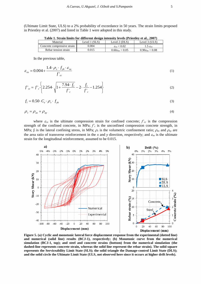
Figure 5a shows the cyclic lateral force-displacement response from the quasi-static test. The
hysteresis loops show a fat and fairly stable shape with some minor pinching, which might be
attributed to the opening and closing of cracks as well as some level of bond degradation. In the same
figure the monotonic curve obtained from numerical analysis is shown; the agreement between this
curve and the envelope of the cyclic response is evident. Figure 5b shows the same monotonic curve
with indications for different limit states. For normal structures, Level 1 (Serviceability Limit State,
SLS) refers to a 50% probability of exceedance in 50 years intensity level; Level 2 (Damage-control
Limit State, DLS) to a 10% probability of exceedance in 50 years intensity level; and Level 3
a) b) c)
A.Cuevas, U.Akguzel, J. Ožbolt and S.Pampanin 5
(Ultimate Limit State, ULS) to a 2% probability of exceedance in 50 years. The strain limits proposed
in Priestley et al. (2007) and listed in Table 1 were adopted in this study.
Table 1. Strain limits for different design intensity levels (Priestley et al., 2007) Material Level 1 (SLS) Level 2 (DLS) Level 3 (ULS)
Concrete compressive strain 0.004 cu < 0.02 1.5 cu
Rebar tension strain 0.015 0.60su < 0.05 0.90su < 0.08
In the previous table,
cc
suyhs
cuf
f
'
4.1004.0
(1)
254.1'
2'
94.71254.2''
c
l
c
lccc
f
f
f
fff (2)
yhvel fCf 50.0 (3)
ayaxv (4)
where cu is the ultimate compression strain for confined concrete; f’cc is the compression
strength of the confined concrete, in MPa; f’c is the unconfined compression concrete strength, in
MPa; fl is the lateral confining stress, in MPa; v is the volumetric confinement ratio; ax and ay are
the area ratio of transverse reinforcement in the x and y direction, respectively; and su is the ultimate
strain for the longitudinal reinforcement, assumed to be 0.015.
Figure 5. (a) Cyclic and monotonic lateral force displacement response from the experimental (dotted line)
and numerical (solid line) results (BCJ-1), respectively; (b) Monotonic curve from the numerical
simulation (BCJ-1, top); and steel and concrete strains (bottom) from the numerical simulation (the
dashed-line represents concrete strain, whereas the solid line represent the rebar strain). The solid square
represents the Serviceability Limit State (SLS); the solid triangle the Damage-control Limit State (DLS);
and the solid circle the Ultimate Limit State (ULS, not observed here since it occurs at higher drift levels).
a) b)
Concrete
Steel
6
Figure 5b also shows the strains measured at the bottom steel rebars and top concrete fibre of
the plastic hinge obtained from the FE model. It is evident how they follow a fairly linear trend
increasing in proportion to the applied lateral displacement. It is interesting to note that both the SLS
and DLS strain limits occur almost simultaneusly at the steel and concrete fibres, at 0.95% and ~4.7%
drift angles, respectively.
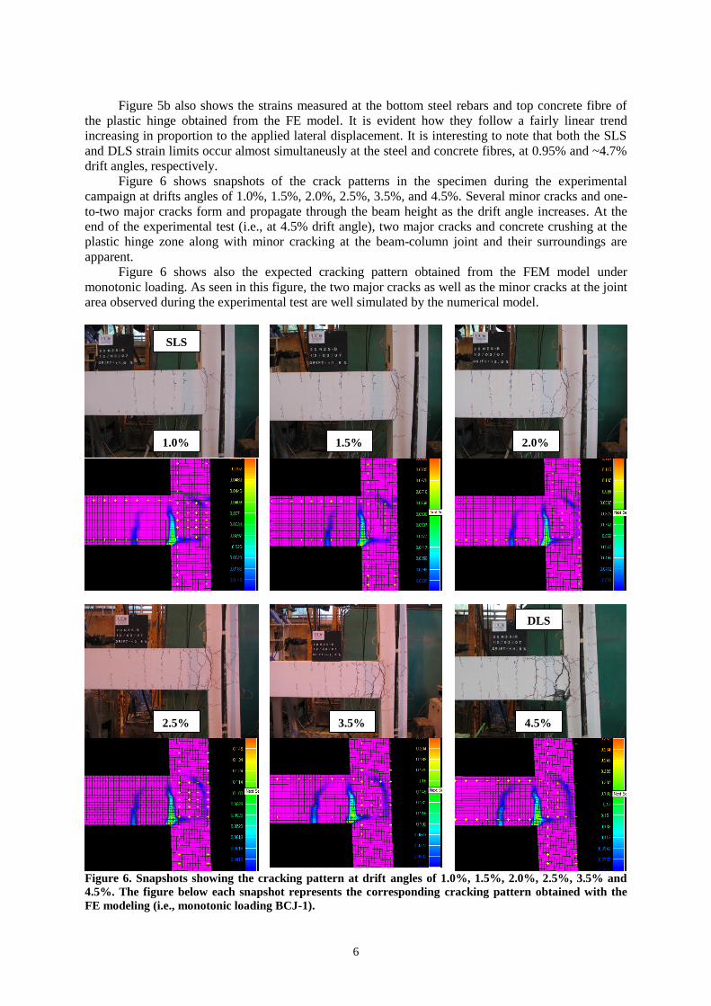
Figure 6 shows snapshots of the crack patterns in the specimen during the experimental
campaign at drifts angles of 1.0%, 1.5%, 2.0%, 2.5%, 3.5%, and 4.5%. Several minor cracks and one-
to-two major cracks form and propagate through the beam height as the drift angle increases. At the
end of the experimental test (i.e., at 4.5% drift angle), two major cracks and concrete crushing at the
plastic hinge zone along with minor cracking at the beam-column joint and their surroundings are
apparent.
Figure 6 shows also the expected cracking pattern obtained from the FEM model under
monotonic loading. As seen in this figure, the two major cracks as well as the minor cracks at the joint
area observed during the experimental test are well simulated by the numerical model.
Figure 6. Snapshots showing the cracking pattern at drift angles of 1.0%, 1.5%, 2.0%, 2.5%, 3.5% and
4.5%. The figure below each snapshot represents the corresponding cracking pattern obtained with the
FE modeling (i.e., monotonic loading BCJ-1).
1.0% 1.5% 2.0%
2.5% 3.5% 4.5%
SLS
DLS
A.Cuevas, U.Akguzel, J. Ožbolt and S.Pampanin 7
One intriguing aspect of this experimental and numerical campaign is the formation of two
major cracks in the plastic hinge region of a well-designed and detailed beam-column joint.
Interestingly enough, this peculiarity agrees very well with observations following the 2010-2011
Canterbury earthquake sequence, where in a number of cases few major crack openings were observed
instead of a well distributed cracking pattern expected in those plastic hinge locations were plastic
deformation was expected to occur. The small number of cracks induces a large amount of
deformation concentrated at a single location, which might lead to a low-cycle fatigue of the
reinforcing steel. This effect may be attributed to low reinforcement ratios, low-rate of strain-
hardening of the steel and/or high concrete tensile strengths, as well as high loading speed (SESOC,
2011, see also Kam et al., 2011).
In the present case, the longitudinal reinforcement ratio s of 0.61% (very close to the lower
bound limit min of 0.45% as per NZS3101:2006), as well as the tensile concrete strength ft of 4MPa
(close enough to an expected upper bound limit of 5MPa) second the above statement.
PARAMETRIC ANALYSES, MONOTONIC LOADING
The objective of the parametric analyses was to identify the most critical parameters (see Figure
1) and combinations of them that affect the cracking pattern and the residual capacity of typical plastic
hinges. This information will be later used as part of a wider research project to calibrate the damage
observed in real structures after recent earthquakes, with the aim of developing analytical models
capable of modelling the residual capacities of plastic hinges to be used for either a pre or post-
earthquake assessment of existing buildings as well as seismic design of new ones (see Cuevas and
Pampanin, 2014, for further details).
Table 2 lists the different range of values for each parameter assumed during the parametric
analyses. As previously mentioned the model BCJ-1 was used as the benchmark, and each series of the
tabulated values was then modified accordingly. The bond characteristics were computed as suggested
by Lettow (2007), with a difference s2-s1 (length of the slipping plateau see Figure 4c) fixed at
0.80mm, and s3 , the slip at which mechanical bond resistance is lost, assumed to be 8.5mm and 10mm
for D12 and D16 bars, respectively (Christoph, 2012).
Table 2. Material and bond characteristics used for numerical simulation and parametric analyses (the
bond parameters are schematically defined in Figure 4c). BCJ-1 BCJ-2 BCJ-3 BCJ-4 BCJ-5 BCJ-6 BCJ-7 BCJ-8 BCJ-9 BCJ-10 BCJ-11 BCJ-12
f'c (MPa) 33 20 20 20 20 40 40 40 40 33 33 33
ft (MPa) 4.00 3.58 3.58 3.58 3.58 5.06 5.06 5.06 5.06 2.00 3.50 5.00
Ec (MPa) 26983 21750 21750 21750 21750 27900 27900 27900 27900 26983 26983 26983
fy (MPa) 320 300 300 500 500 300 300 500 500 320 320 320
fu (MPa) 440 412.5 412.5 687.5 687.5 412.5 412.5 687.5 687.5 440 440 440
s (%) 0.61 0.61 1.09 0.61 1.09 0.61 1.09 0.61 1.09 0.61 0.61 0.61
=m+f (MPa) 13.7 10.7 11.9 10.7 11.9 15.1 16.8 15.1 16.8 13.7 13.7 13.7
m (MPa) 8.21 6.39 7.11 6.39 7.11 9.04 10.06 9.04 10.06 8.21 8.21 8.21
k1 (MPa/mm) 35.2 28.6 34.1 28.6 34.1 38.7 45.1 38.7 45.1 35.2 35.2 35.2
k2 (MPa/mm) 1.28 1.04 0.85 1.04 0.85 1.41 1.13 1.41 1.13 1.28 1.28 1.28
ksec (MPa/mm) 16.0 13.0 14.2 13.0 14.2 17.6 18.8 17.6 18.8 16.0 16.0 16.0
s1 (mm) 0.86 0.82 0.84 0.82 0.84 0.86 0.89 0.86 0.89 0.86 0.86 0.86
Influence of concrete and steel strength, f’c, fy, and longitudinal reinforcement ratio, ρs:
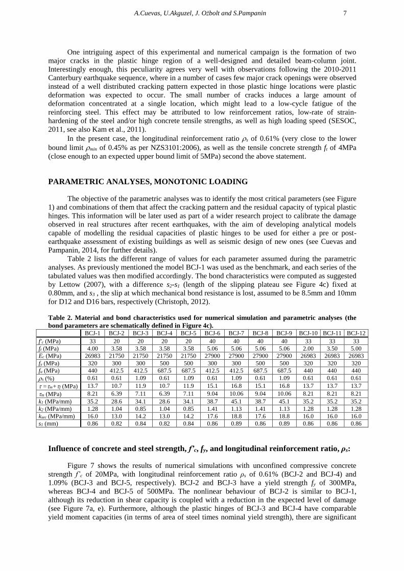
Figure 7 shows the results of numerical simulations with unconfined compressive concrete
strength f’c of 20MPa, with longitudinal reinforcement ratio ρs of 0.61% (BCJ-2 and BCJ-4) and
1.09% (BCJ-3 and BCJ-5, respectively). BCJ-2 and BCJ-3 have a yield strength fy of 300MPa,
whereas BCJ-4 and BCJ-5 of 500MPa. The nonlinear behaviour of BCJ-2 is similar to BCJ-1,
although its reduction in shear capacity is coupled with a reduction in the expected level of damage
(see Figure 7a, e). Furthermore, although the plastic hinges of BCJ-3 and BCJ-4 have comparable
yield moment capacities (in terms of area of steel times nominal yield strength), there are significant
8
differences in the nonlinear behaviour; while BCJ-3 has a peak shear capacity at SLS and then drops
abruptly (see Figure 7f); the nonlinear behaviour of BCJ-4 is more uniform with a strength drop at
higher drift angles ~3% (see Figure 7g). Nevertheless, the expected cracking pattern is comparable in
both cases with joints severely damaged at drift angles close to the ULS. BCJ-5 behaves in a similar
fashion as BCJ-3, although more damage in the joint is expected due to a higher shear demand at
higher drifts (see Figure 7h).
Figure 7. Monotonic story shear vs displacement response from the numerical results; and steel and
concrete strains for simulations: a) BCJ-2; b) BCJ-3; c) BCJ-4; and d) BCJ-5 (the dashed-line represents
concrete strains, whereas the solid line represent the rebar strain; the small snapshot represent the
cracking pattern at SLS). Snapshots for e) BCJ-2 at DLS; f) BCJ-3 at drift equivalent to DLS of BCJ-2; g)
BCJ-4 at drift equivalent to DLS of BCJ-4; and h) BCJ-5 at DLS. The solid square represents the
Serviceability Limit State (SLS); the solid triangle the Damage-control Limit State (DLS); and the solid
circle the Ultimate Limit State (ULS, not observed here).
a) b)
c) d)
e)
f)
g)
h)
A.Cuevas, U.Akguzel, J. Ožbolt and S.Pampanin 9
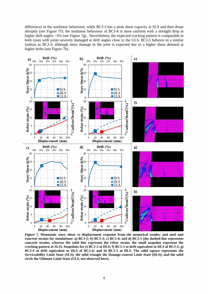
Figure 8 shows the results of numerical simulations with unconfined compressive concrete
strength f’c of 40MPa, with longitudinal reinforcement ratio ρs of 0.61% (BCJ-6 and BCJ-8) and
1.09% (BCJ-7 and BCJ-9, respectively). BCJ-6 and BCJ-7 have a yield strength fy of 300MPa,
whereas BCJ-8 and BCJ-9 of 500MPa. The nonlinear behaviour of BCJ-6 is similar to BCJ-1,
although a single major crack opening instead of two major cracks is expected to occur (see Figure 8a,
e).
Figure 8. Monotonic story shear vs displacement response from the numerical results; and steel and
concrete strains for simulations: a) BCJ-6; b) BCJ-7; c) BCJ-8; and d) BCJ-9 (the dashed-line represents
concrete strains, whereas the solid line represent the rebar strain; the small snapshot represent the
cracking pattern at SLS). Snapshots for e) BCJ-6 at DLS; f) BCJ-7 at drift equivalent to DLS of BCJ-6; g)
BCJ-8 at 4.5% drift; and h) BCJ-9 at 4.5% drift. The solid square represents the Serviceability Limit
State (SLS); the solid triangle the Damage-control Limit State (DLS); and the solid circle the Ultimate
Limit State (ULS, not observed here).
a) b)
c) d)
e)
f)
g)
h)
10
Furthermore, although the plastic hinges of BCJ-7 and BCJ-8 have comparable yield moment
capacities (in terms of area of steel times nominal yield strength), their nonlinear behaviour and
cracking pattern show significant differences; less and major cracks are expected to occur for smaller
fy and larger ρs (i.e., BCJ-7). BCJ-9 behaves in a similar fashion as BCJ-3 and BCJ-5, although more
shear capacity strength drop is expected to occur (see Figure 8h).
By comparing Figure 7 and Figure 8, it is evident how f’c affects the cracking level at the joint.
Furthermore, it is interesting to note how the residual shear strength of the beam-column joints is
influenced also by f’c irrespective of fy and ρs, being on average 23kN and 30kN for f’c of 20MPa and
30MPa, respectively. Therefore, the increased level of damage observed in Figure 7 with respect to
Figure 8 can be attributed to a reduced shear capacity due to a low compressive strength. In addition,
the previous figures show drifts at SLS fairly constant irrespective of f’c, fy and ρs (1.0% on average,
except for BCJ-2 and BCJ-6 where values around 0.8% were obtained). The above might be explained
with the fact that the yield curvature is relatively insensitive to the axial load and reinforcement ratio,
depending mainly on structural geometry and material sizes (Priestley et al., 2007).
Influence of ft on the cracking pattern and limit states:
In the previous figures it was observed that variations on f’c affect the expected cracking pattern
in the beam-column joints. Since the unconfined compressive concrete strength has a strong impact on
the tensile concrete strength, three additional simulations with ft of 2MPa (BCJ-10), 3.5MPa (BCJ-11)
and 5MPa (BCJ-12), representing realistic values for f’c of 30-to-35MPa, were adopted by keeping
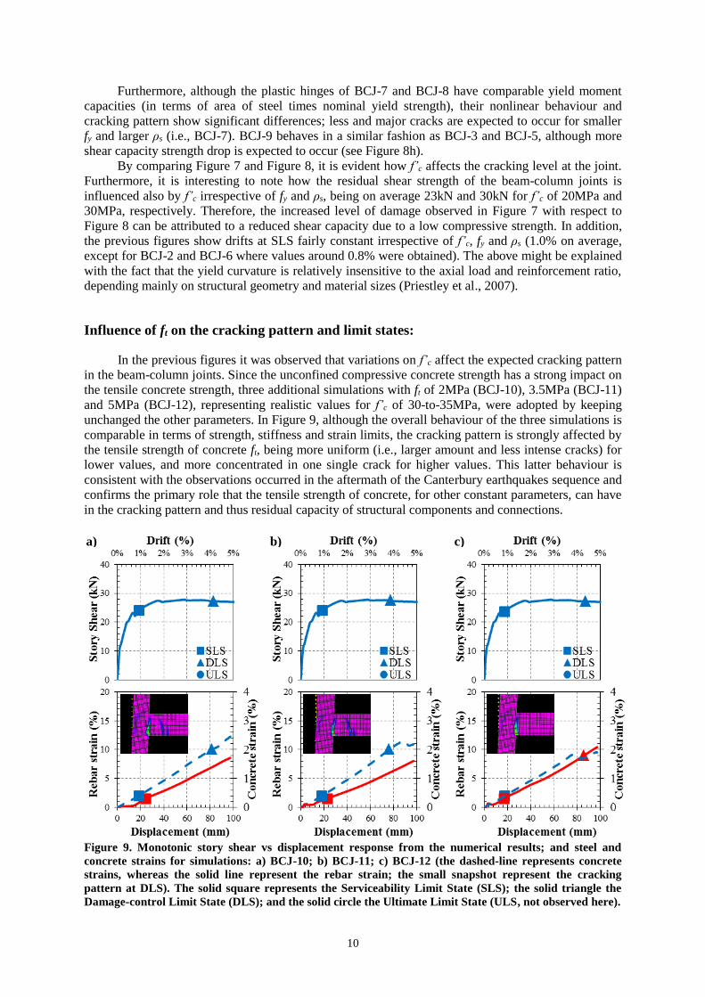
unchanged the other parameters. In Figure 9, although the overall behaviour of the three simulations is
comparable in terms of strength, stiffness and strain limits, the cracking pattern is strongly affected by
the tensile strength of concrete ft, being more uniform (i.e., larger amount and less intense cracks) for
lower values, and more concentrated in one single crack for higher values. This latter behaviour is
consistent with the observations occurred in the aftermath of the Canterbury earthquakes sequence and
confirms the primary role that the tensile strength of concrete, for other constant parameters, can have
in the cracking pattern and thus residual capacity of structural components and connections.
Figure 9. Monotonic story shear vs displacement response from the numerical results; and steel and
concrete strains for simulations: a) BCJ-10; b) BCJ-11; c) BCJ-12 (the dashed-line represents concrete
strains, whereas the solid line represent the rebar strain; the small snapshot represent the cracking
pattern at DLS). The solid square represents the Serviceability Limit State (SLS); the solid triangle the
Damage-control Limit State (DLS); and the solid circle the Ultimate Limit State (ULS, not observed here).
a) b) c)
A.Cuevas, U.Akguzel, J. Ožbolt and S.Pampanin 11
CONCLUSIONS
This paper presents the results of experimental and numerical investigations on well-designed
reinforced concrete beam-to-column joints, targeting at identifying and understanding qualitatively
and quantitatively the effect of parameters such as bond deterioration, steel and concrete material
properties, as well as the amount of longitudinal reinforcement, on the cracking pattern and nonlinear
behaviour of reinforced concrete plastic hinges. This study is part of a wider research project aiming at
investigating the seismic residual capacity of reinforced concrete frames. The information contained
herein will be later used to calibrate the damage observed in real structures after recent earthquakes,
with the aim of developing analytical models capable of modelling the residual capacities of plastic
hinges to be used for seismic design as well as either a pre or post-earthquake assessment of existing
buildings.
Two major cracks in the plastic hinge region were observed during the numerical simulation and
experimental validation, which agrees well with observations following the 2010-2011 Canterbury
earthquake sequence, where in a number of cases few major crack openings were observed instead of
a well distributed cracking pattern expected in those plastic hinge locations, condition attributed to
either a low-rate of strain-hardening of the steel, low reinforcement ratio, high loading speed, and high
concrete tensile strengths as in the present case. The negative aspect of the small number of cracks in a
plastic hinge is mainly the large amount of deformation induced at a single location, leading a low-
cycle fatigue of the reinforcing steel and consequently, of the whole plastic hinge region.
Parametric analyses under monotonic loading have shown that less amount and major crack
openings are expected to occur for smaller fy and larger ρs values. Moreover, it was observed that
although the overall behaviour in terms of strength, stiffness and strain limits is not significantly
affected by variations in ft, it strongly affects the expected cracking pattern in the beam-column joints,
the latter being more uniform (i.e., larger amount and less intense cracks) for lower ft values.
Furthermore, the seismic residual shear strength of the beam-column joints was observed to be
influenced also by f’c irrespective of the fy and ρs values. Parametric analyses under cyclic loading is
under development and will follow as part of the overall project.
REFERENCES
Abdalla, J. A., Hawileh, R. A., Abdelrahman, K. (2009) “Energy-based prediction of low-cycle fatigue life of BS
460B and BS B500B steel bars,” Materials and Design, 30:4405-4413.
ACI. (2001). "Acceptance Criteria for Moment Frames Based on Structural Testing (T1.1-01) and Commentary
(T1.1R-01)," A. I. T. G. 1, ed., Farmington Hills, Michigan.
Cuevas, A., Pampanin, S. (2014) “Accounting for residual capacity of reinforced concrete plastic hinges: current
practice and proposed framework,” 2014 New Zealand Society of Earthquake Engineering Conference,
Auckland, New Zealand.
Eligehausen, R., Genesio, G., Ozbolt, J., Pampanin, S. (2009) “3D analysis of seismic response of RC beam-
column exterior joints before and after retrofit,” Concrete Repair, Rehabilitation and Retrofitting II, 1141-
1147.
Hawileh, R., Rahman, A., Tabatabai, H. (2010) “Evaluation of the low-cycle fatigue life in ASTM A706 and
A615 grade 60 steel reinforcing bars,” Journal of Materials in Civil Engineering, 22(1):65-76.
Kam, W. Y., Pampanin, S., Elwood, K. (2011) “Seismic performance of reinforced concrete buildings in the 22
February Christchurch (Lyttelton) Earthquake,” Bulletin of the New Zealand Society for Earthquake
Engineering, 44(4):239-278.
Kunnath, S. K., El-Bahy, A., Taylor, A. W., Stone, W. C. (1997) “Cumulative seismic damage of reinforced
concrete bridge piers,” National Institute of Standards and technology, Technical Report NISTIR-6075.
Lettow, S. (2006) “Ein Verbundelement für nichtlineare Finite Elemente Analysen – Anwendung auf
Übergreifungsstöße (A bond element for nonlinear finite element analysis – Applied on splices),” PhD
Dissertation, IWB, Universität Stuttgart, Germany (in German).
Mahrenholtz, C (2012) “Seismic bond model for concrete reinforcement and the application to column-to-
foundation connections,” PhD thesis, Institut fur Werkstoffe im Bauwesen der Universitat Stuttgart.
Mander, J. B., Cheng, C. T. (1999) “Replaceable hinge detailing for bridge columns,” SP-187 Seismic Response
of Concrete Bridges, ACI Symposium Publications.
12
Mander, J. B., Panthaki, F. D., Kasalanati, A. (1994) “Low-cycle fatigue behaviour of reinforcing steel,” Journal
of Materials in Civil Engineering, 6(4):453-468.
Ožbolt J, Yijun L, Kozar I. (2001) “Microplane model for concrete with relaxed kinematic constraint,”
International Journal of Solids and Structures. 2001, 38:2638-711.
Pampanin, S. (2012) “Reality-check and renewed challenges in earthquake engineering: implementing low-
damage structural systems – from theory to practice,” Fifteenth World Conference in Earthquake
Engineering, Lisbon, Portugal.
Priestley, M. J. N., Calvi, G. M, Kowalski, M. J. (2007) Displacement-based seismic design of structures,
IUSS Press, Pavia, Italy.
SESOC (2011) “Preliminary observations from Christchurch earthquakes” Structural Engineering Society, New
Zealand.