Embed Size (px)
Citation preview

1
Preliminary Investigation into Central Receiver Design for Optimal Optical
and Thermal Performance
Marcel Slootweg
Supervisors: K.J. Craig, J.P. Meyer
Clean Energy Research Group (CERG),
Department of Mechanical and Aeronautical Engineering,
UNIVERSITY OF PRETORIA
2
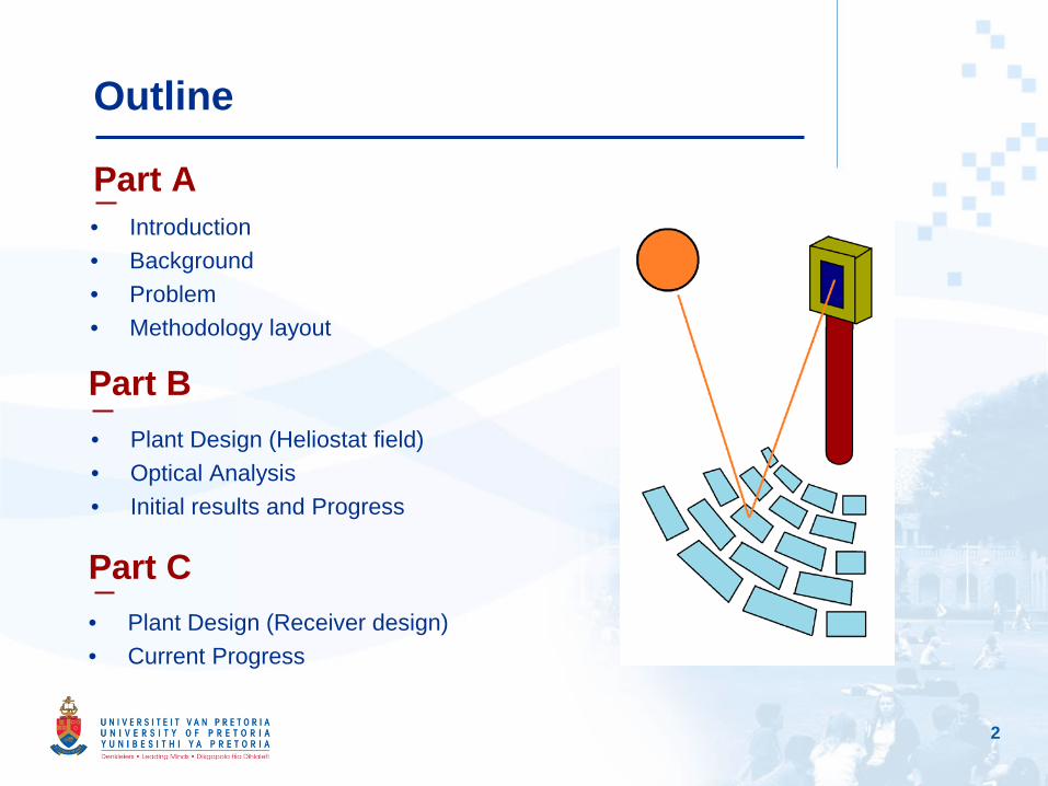
Outline
• Plant Design (Heliostat field)• Optical Analysis• Initial results and Progress
Part B
Part C• Plant Design (Receiver design)• Current Progress
• Introduction• Background• Problem• Methodology layout
Part A
3
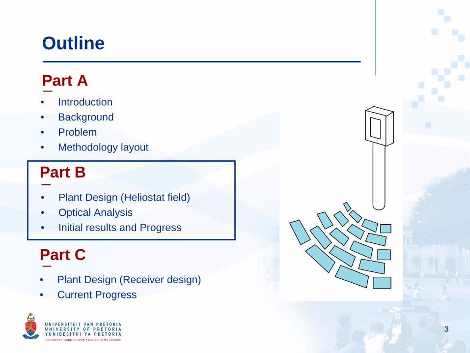
Outline
• Plant Design (Heliostat field)• Optical Analysis• Initial results and Progress
Part B
Part C• Plant Design (Receiver design)• Current Progress
• Introduction• Background• Problem• Methodology layout
Part A

4
Outline
• Plant Design (Heliostat field)• Optical Analysis• Initial results and Progress
Part B
Part C• Plant Design (Receiver design)• Current Progress
• Introduction• Background• Problem• Methodology layout
Part A

5
Part A
• Trends show shift to renewable energy sector, especially solar energy.
• CSP technology has advantage of storing heat during times of no sun.
• Central Receivers consist of an array of heliostats that reflect solar radiation to a central receiver.
• Designs may differ significantly.
Introduction

6
Part A
• Great need to increase efficiencies of CSP plants.
• Central Receiver systems experience great losses.
• To increase the efficiency of receivers, one needs to decrease thermal losses.
• Wide variety of designs are currently available.
Receiver Overview
From left to right: External Tubular receiver (Lata, et al., 2008); SCRAP receiver (Lubkoll, et al., 2015); Hybrid Pressurized Air receiver (Kretzschmar, et al., 2012); Indirect Exposure Cavity Falling Film receiver (Ho, Iversion, 2014)

7
Part A
Design to be tested and optimized numerically with integrated optical and thermal models.
Objective
8
Part A
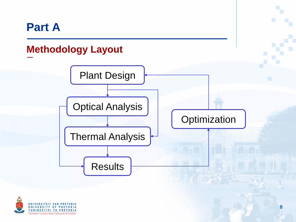
Methodology Layout
Plant Design
Optical Analysis
Thermal Analysis
Results
Optimization
9
Part B
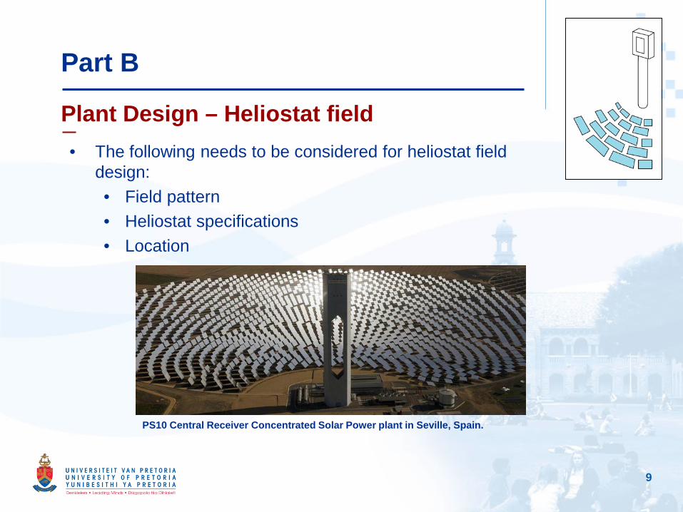
Plant Design – Heliostat field• The following needs to be considered for heliostat field
design:• Field pattern• Heliostat specifications• Location
PS10 Central Receiver Concentrated Solar Power plant in Seville, Spain.
10
Part B
Optical Analysis – Using SolTrace
• The Optical Analysis simulations are done using SolTrace. • For simulations to take place, the following needs to be
defined:• Sun specifications• Solar field specifications (Optical properties and
system layout)• Trace specifications (Post-processing relevance)
11
Part B
Optical Analysis – Defining the Sun
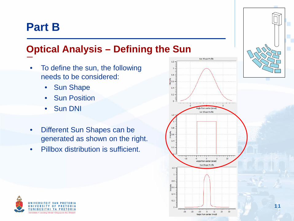
• To define the sun, the following needs to be considered:• Sun Shape• Sun Position• Sun DNI
• Different Sun Shapes can be generated as shown on the right.
• Pillbox distribution is sufficient.
12
Part B
Optical Analysis – Solar Tracking and DNI
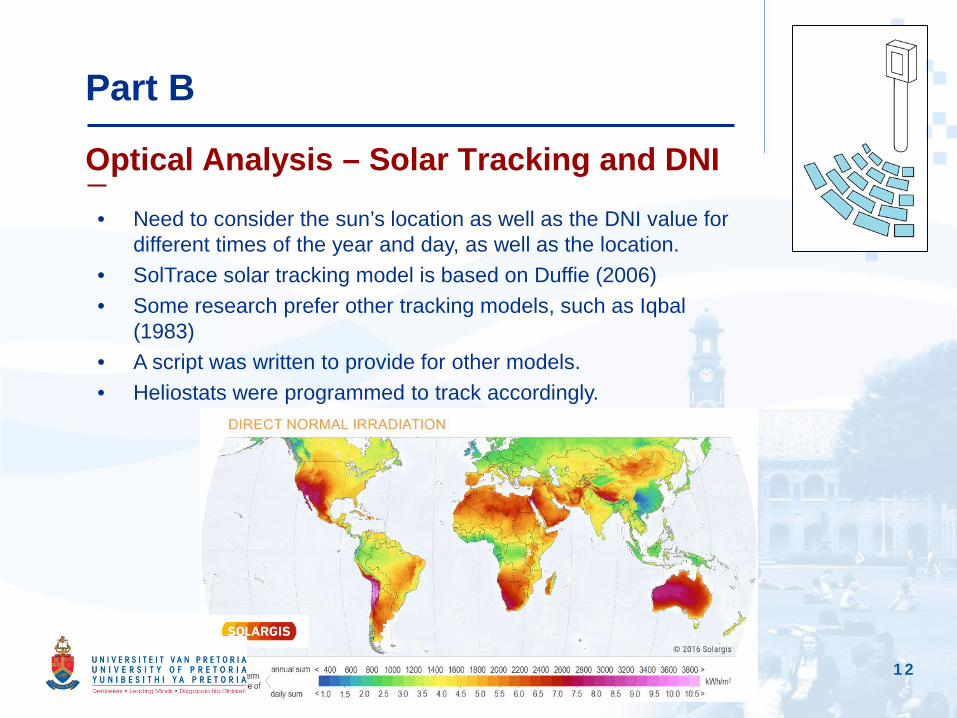
• Need to consider the sun’s location as well as the DNI value for different times of the year and day, as well as the location.
• SolTrace solar tracking model is based on Duffie (2006)• Some research prefer other tracking models, such as Iqbal
(1983)• A script was written to provide for other models.• Heliostats were programmed to track accordingly.

13
Part B
Optical Analysis – DNI model
• Direct Normal Irradiance (DNI) differs from location as well as time.• Numerous models available to estimate the values, such as Iqbal’s
Parameterization Model A, B and C as well ASHRAE.• Models calculate DNI taking into account the following variables:
Transmittance of:•Water vapor (Function of relative humidity and temperature)•Mixed gases •Ozone (Function of ozone layer thickness)•Aerosols in air•Raleigh Scattering (Function of Altitude)
• Coupling the variables with location and time provides realistic DNI fluctuations.
14
Part B
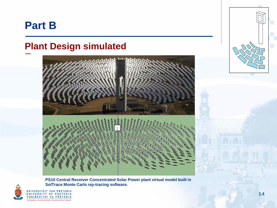
Plant Design simulated
PS10 Central Receiver Concentrated Solar Power plant virtual model built in SolTrace Monte Carlo ray-tracing software.
15
Part B
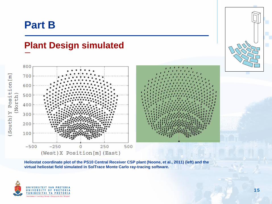
Plant Design simulated
Heliostat coordinate plot of the PS10 Central Receiver CSP plant (Noone, et al., 2011) (left) and the virtual heliostat field simulated in SolTrace Monte Carlo ray-tracing software.
16
Part B
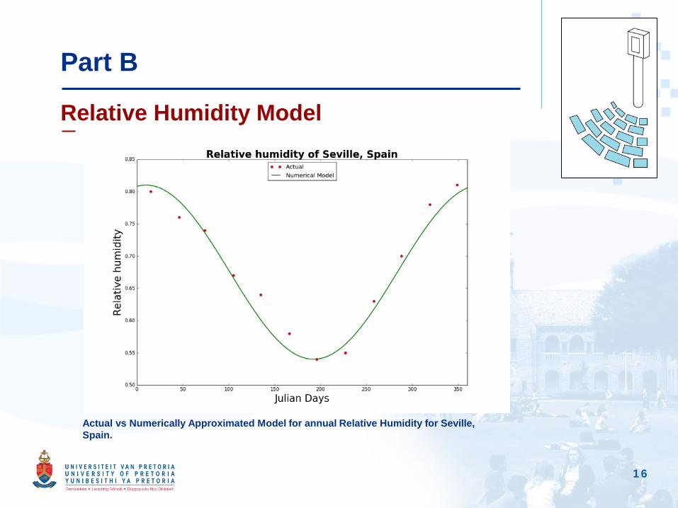
Relative Humidity Model
Actual vs Numerically Approximated Model for annual Relative Humidity for Seville, Spain.
17
Part B
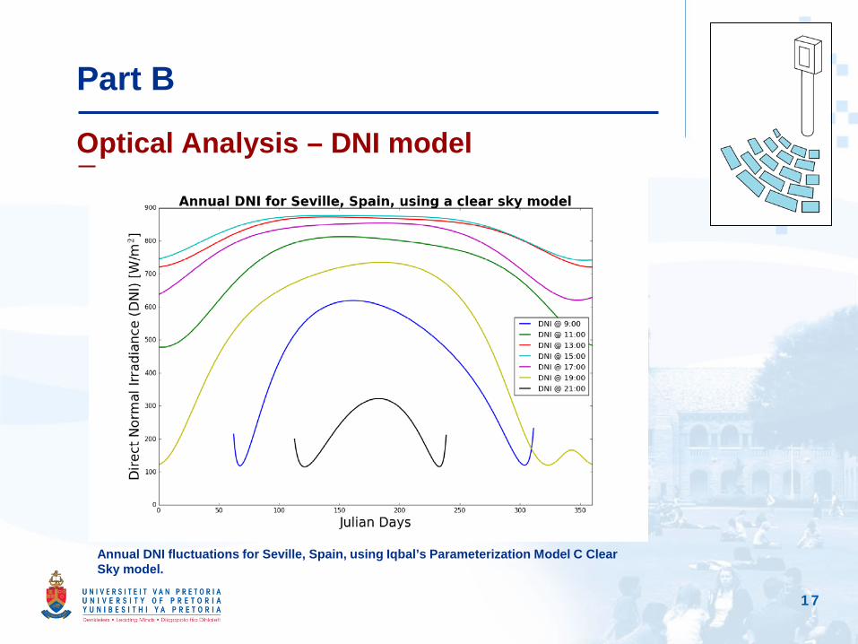
Optical Analysis – DNI model
Annual DNI fluctuations for Seville, Spain, using Iqbal’s Parameterization Model C Clear Sky model.
18
Part B
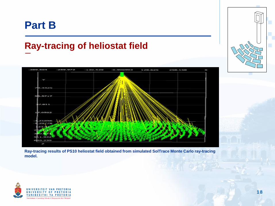
Ray-tracing of heliostat field
Ray-tracing results of PS10 heliostat field obtained from simulated SolTrace Monte Carlo ray-tracing model.

19
Part B
Solar Flux on flat surface receiver aperture
Post-processed solar flux map generatred by SolTrace for PS10 Heliostat field.
20
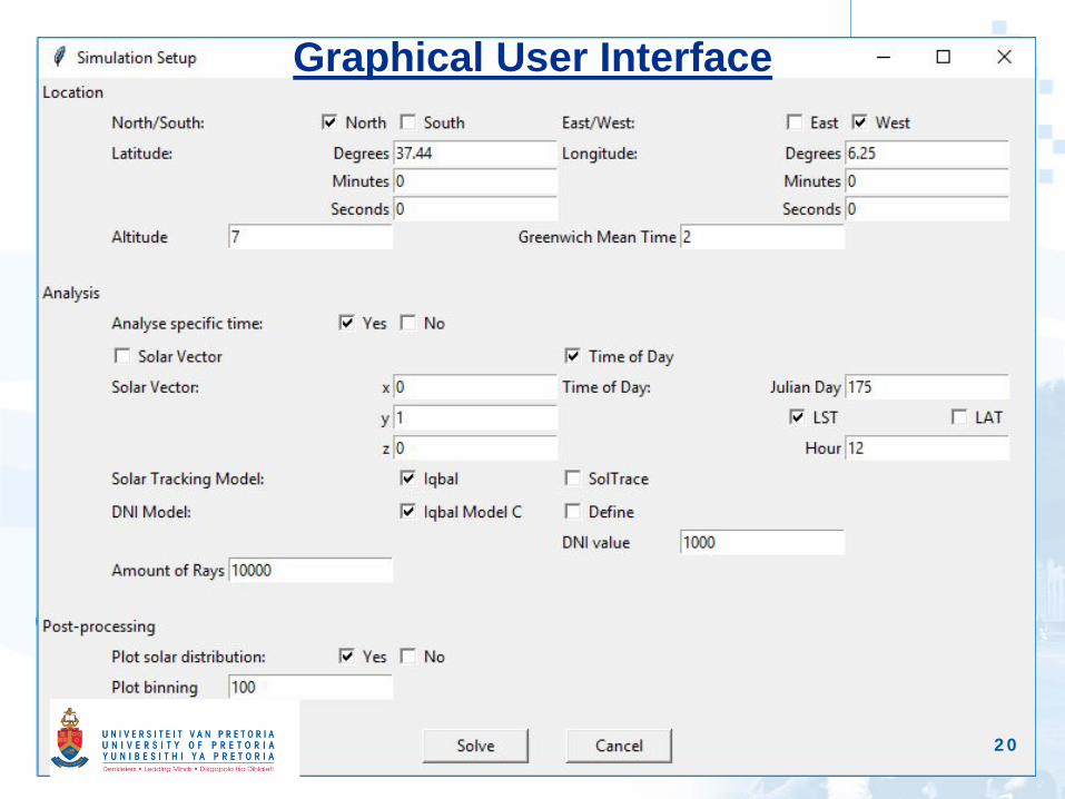
Graphical User Interface

21
Graphical User Interface

22
Graphical User Interface
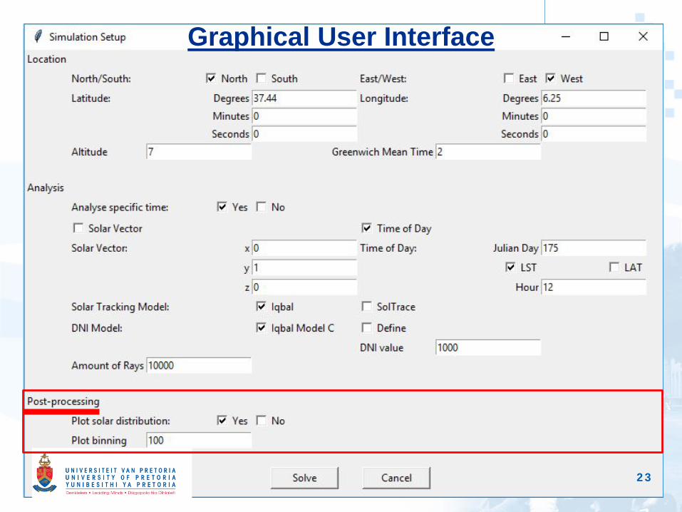
23
Graphical User Interface
24
Part C
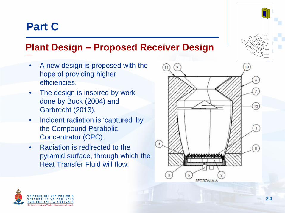
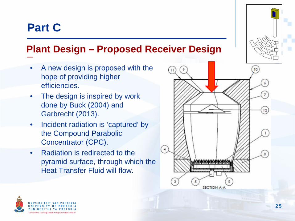
• A new design is proposed with the hope of providing higher efficiencies.
• The design is inspired by work done by Buck (2004) and Garbrecht (2013).
• Incident radiation is ‘captured’ by the Compound Parabolic Concentrator (CPC).
• Radiation is redirected to the pyramid surface, through which the Heat Transfer Fluid will flow.
Plant Design – Proposed Receiver Design
25
Part C
• A new design is proposed with the hope of providing higher efficiencies.
• The design is inspired by work done by Buck (2004) and Garbrecht (2013).
• Incident radiation is ‘captured’ by the Compound Parabolic Concentrator (CPC).
• Radiation is redirected to the pyramid surface, through which the Heat Transfer Fluid will flow.
Plant Design – Proposed Receiver Design

26
Part C
• A new design is proposed with the hope of providing higher efficiencies.
• The design is inspired by work done by Buck (2004) and Garbrecht (2013).
• Incident radiation is ‘captured’ by the Compound Parabolic Concentrator (CPC).
• Radiation is redirected to the pyramid surface, through which the Heat Transfer Fluid will flow.
Plant Design – Proposed Receiver Design
27
Part C
Plant Design – Receiver
• The receiver is the interface where the optical and thermal analysis meet.
• Software used for analyses:• Optical Analysis – SolTrace Monte Carlo ray-tracing
software.• Thermal Analysis – Ansys Fluent CFD simulation
software.• Solution to be found for the transition between software.• Design could be built in each software separately – not
ideal for optimization and automation.• Other solution is proposed.
28
Part C
Build model for both software
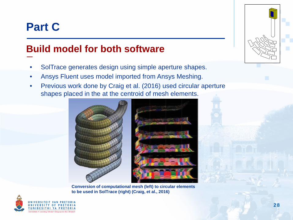
• SolTrace generates design using simple aperture shapes.• Ansys Fluent uses model imported from Ansys Meshing.• Previous work done by Craig et al. (2016) used circular aperture
shapes placed in the at the centroid of mesh elements.
Conversion of computational mesh (left) to circular elements to be used in SolTrace (right) (Craig, et al., 2016)
29
Part C
Software integration – Current Progress
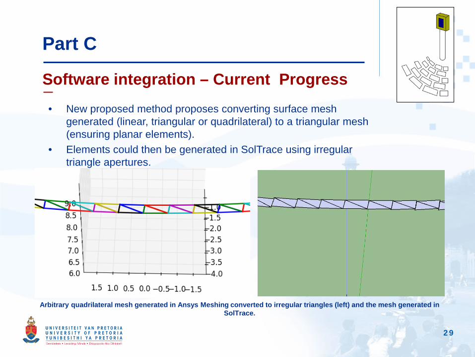
• New proposed method proposes converting surface mesh generated (linear, triangular or quadrilateral) to a triangular mesh (ensuring planar elements).
• Elements could then be generated in SolTrace using irregular triangle apertures.
Arbitrary quadrilateral mesh generated in Ansys Meshing converted to irregular triangles (left) and the mesh generated in SolTrace.
30
Discussion and Conclusion
Research to follow
• Model to be completed, including:• Completing intergration between SolTrace and Ansys Fluent.• Completing Ansys CFD model.• Expanding existing models.• Expanding interface options.
• Test model for different input specifications.• Provide parameters for optimization.• Set up optimization models.

31
Acknowledgements
• The Clean Energy Research Group of the University of Pretoria.
• Supervisor Professor Ken Craig and Co-supervisor Professor JP Meyer.
• The National Research Foundation (NRF).

32
Thank You
Thank You
Questions?