Embed Size (px)
Citation preview

GeoPro Consulting Limited (905) 237-8336 [email protected]
Units 25 to 27, 40 Vogell Road, Richmond Hill, Ontario L4B 3N6
T: (905) 237-8336 E: [email protected]
Units 25-27, 40 Vogell Road, Richmond Hill, Ontario L4B 3N6
Preliminary Geotechnical Investigation
Lakeview Boulevard Improvements
Town of Ajax, Ontario
Prepared For:
Dionne Bacchus & Associates Consulting Engineers Ltd.
GeoPro Project No.: 16-1296-01 Revised
Report Date: November 3, 2016

GeoPro Project: 16-1296-01 Preliminary Geotechnical Investigation – Lakeview Boulevard Improvements Town of Ajax, Ontario
Unit 25 to 27, 40 Vogell Road, Richmond Hill, ON Tel: 905-237-8336 Fax: 905-248-3699 www.geoproconsulting.ca i [email protected]
Table of Contents 1. INTRODUCTION ...................................................................................................................................... 1
3. SUBSURFACE CONDITIONS .................................................................................................................... 2
3.1 Soil Conditions .............................................................................................................................. 3
3.2 Groundwater Conditions .............................................................................................................. 4
4. DISCUSSION AND RECOMMENDATIONS ............................................................................................... 5
4.1 Site and Project Description ......................................................................................................... 5
4.2 Pavement Design .......................................................................................................................... 6
4.2.1 Existing Pavement Conditions ..................................................................................................... 6
4.2.2 Lakeview Boulevard Pavement Rehabilitation ............................................................................ 6
4.2.3 North Driveway Pavement Reconstruction ................................................................................. 8
4.2.4 Pavement Recommendations and Construction Features .......................................................... 9
4.2.4.1 Pavement Material Types ..................................................................................................... 9
4.2.4.2 Asphalt Cement Grade ......................................................................................................... 9
4.2.4.3 Tack Coat .............................................................................................................................. 9
4.2.4.4 Compaction .......................................................................................................................... 9
4.2.4.5 Pavement Tapers .................................................................................................................. 9
4.2.4.6 Stripping, Sub-excavation and Grading .............................................................................. 10
4.2.4.7 Construction ....................................................................................................................... 10
4.2.4.8 Drainage.............................................................................................................................. 10
4.2.5 Reuse and Disposal of Existing Pavement Materials ................................................................. 11
4.3 Underground Site Services (Storm Sewer) ................................................................................. 11
4.3.1 Trenching Excavation ................................................................................................................. 11
4.3.2 Bedding ...................................................................................................................................... 13

GeoPro Project: 16-1296-01 Preliminary Geotechnical Investigation – Lakeview Boulevard Improvements Town of Ajax, Ontario
Unit 25 to 27, 40 Vogell Road, Richmond Hill, ON Tel: 905-237-8336 Fax: 905-248-3699 www.geoproconsulting.ca ii [email protected]
4.3.3 Backfilling of Trenches ............................................................................................................... 13
5 CLOSURE ..............................................................................................................................................15
Drawings No.
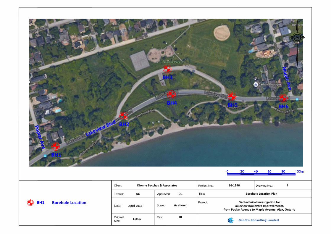
Borehole Location Plan 1
Enclosures No.
Notes on Sample Description 1A
Explanation of Terms Used in the Record of Boreholes 1B
Borehole Logs 2 to 7
Figures No.
Grain Size Distribution 1 to 2
Atterberg Limits Test Results 3
Limitations to the Report

GeoPro Project: 16-1296-01 Preliminary Geotechnical Investigation – Lakeview Boulevard Improvements Town of Ajax, Ontario
Unit 25 to 27, 40 Vogell Road, Richmond Hill, ON Tel: 905-237-8336 Fax: 905-248-3699 www.geoproconsulting.ca 1 [email protected]
1. INTRODUCTION
GeoPro Consulting Limited (GeoPro) was retained by Dionne Bacchus & Associates Consulting
Engineers Ltd. (the Client) to conduct a preliminary geotechnical investigation for the Class EA
Study of the proposed Lakeview Boulevard Improvements, in the Town of Ajax, Ontario.
The purpose of this geotechnical investigation was to obtain information on the existing
subsurface conditions by means of a limited number of boreholes, in-situ tests and laboratory
tests of soil samples to provide required geotechnical design information. Based on GeoPro’s
interpretation of the data obtained, geotechnical comments and recommendations related to the
road pavement design, drainage and storm sewer installation are provided.
The report is prepared with the condition that the design will be in accordance with all applicable
standards and codes, regulations of authorities having jurisdiction, and good engineering practice.
Further, the recommendations and opinions in this report are applicable only to the proposed
project as described above. Ongoing liaison and communication with GeoPro during the design
stage and construction phase of the project is strongly recommended to confirm that the
recommendations in this report are applicable and/or correctly interpreted and implemented.
Also, any queries concerning the geotechnical aspects of the proposed project shall be directed
to GeoPro for further elaboration and/or clarification.
This report is provided on the basis of the terms of reference presented in our approved proposal
prepared based on our understanding of the project. If there are any changes in the design
features relevant to the geotechnical analyses, or if any questions arise concerning the
geotechnical aspects of the codes and standards, this office should be contacted to review the
design. It may then be necessary to carry out additional borings and reporting before the
recommendations of this report can be relied upon.
This report deals with geotechnical issues only. The geo-environmental (chemical) aspects of the
subsurface conditions, including the consequences of possible surface and/or subsurface
contamination resulting from previous activities or uses of the site and/or resulting from the
introduction onto the site of materials from off-site sources, were not investigated and were
beyond the scope of this assignment.
The site investigation and recommendations follow generally accepted practice for geotechnical
consultants in Ontario. Laboratory testing for most part follows ASTM or CSA Standards or
modifications of these standards that have become standard practice in Ontario.
This report has been prepared for the Client only. Third party use of this report without GeoPro’s
consent is prohibited. The limitations to the report presented in this report form an integral part
of the report and they must be considered in conjunction with this report.

GeoPro Project: 16-1296-01 Preliminary Geotechnical Investigation – Lakeview Boulevard Improvements Town of Ajax, Ontario
Unit 25 to 27, 40 Vogell Road, Richmond Hill, ON Tel: 905-237-8336 Fax: 905-248-3699 www.geoproconsulting.ca 2 [email protected]
2. FIELD AND LABORATORY WORK
The field work for the geotechnical investigation was carried out on May 3, 2016, during which
time six (6) boreholes (Boreholes BH1 to BH6) were advanced at the locations shown on Borehole
Location Plan, Drawing 1. The boreholes were drilled to a depth of about 5 m below the existing
ground surface.
The boreholes were advanced using continuous flight auger equipment supplied by a drilling
specialist subcontracted to GeoPro. Samples were retrieved with a 51 mm (2 inch) O.D. split-
barrel (split spoon) sampler driven with a hammer weighing 624 N and dropping 760 mm (30
inches) in accordance with the Standard Penetration Test (SPT) method.
The field work for this investigation was monitored by a member of our engineering staff who also
determined the approximate borehole locations in the field, logged the boreholes and cared for
the recovered samples.
All soil samples obtained during this investigation were brought to our laboratory for further
examination and geotechnical classification testing (including water content, grain size
distribution, and Atterberg limit tests, when applicable) on selected soil samples. The results of
grain size distribution and Atterberg limit tests of the selected soil samples are shown in Figures
1 to 3.
Groundwater condition observations were made in the open boreholes during drilling and upon
completion of drilling. All boreholes were backfilled and sealed upon completion of drilling except
for borehole BH4. One monitoring well (51 mm in diameter) was installed in Borehole BH4 for
groundwater level monitoring.
It should be noted that the elevations at the as-drilled borehole locations were not available at
the time of preparing the report. The borehole locations plotted on Borehole Location Plan,
Drawing 1 were based on the measurement of the site features and should be considered to be
approximate.
3. SUBSURFACE CONDITIONS
The borehole locations are shown on Borehole Location Plan Drawing 1. Notes on sample
descriptions are presented in Enclosure No. 1A. Explanation of terms used in the record of
boreholes is presented in Enclosure No. 1B. The subsurface conditions in the boreholes (BH1 to
BH6) are presented in the individual borehole logs (Enclosure Nos. 2 to 7 inclusive). Detailed
descriptions of the major soil strata encountered in the boreholes drilled at the site are provided
in the following.

GeoPro Project: 16-1296-01 Preliminary Geotechnical Investigation – Lakeview Boulevard Improvements Town of Ajax, Ontario
Unit 25 to 27, 40 Vogell Road, Richmond Hill, ON Tel: 905-237-8336 Fax: 905-248-3699 www.geoproconsulting.ca 3 [email protected]
3.1 Soil Conditions
Asphalt Pavement
All boreholes were advanced through the existing pavement. The existing pavement structure
encountered from Boreholes BH1 to BH6 is summarized as follows:
LOCATION THICKNESS OF PAVEMENT STRUCTURE
Road Section
Borehole Number
Asphalt (mm)
Granular Base/Subbase
(mm) Subgrade Type
Lakeview Boulevard
BH1 to BH2 and BH4 to BH6
110 - 135 335 - 960 Sandy silt fill,
clayey silt fill or gravelly sand fill
North Driveway
BH3 90 250 Clayey silt fill
* The thickness of 960 mm of granular base/subbase in BH4 was not used to calculate the existing pavement structure average thickness on Lakeview Boulevard.
Sieve analyses were completed on three samples of the recovered granular base/subbase
materials, and the results were compared to OPSS.MUNI 1010 Granular A and Granular B Type I
specifications. The grain size distribution curves for three samples are presented in Figure 1, with
a summary of the results provided in the table below.
SAMPLE OPSS.MUNI 1010 GRANULAR A OPSS.MUNI 1010 GRANULAR B TYPE I
BH3 AS1 Does not meet OPSS.MUNI 1010 due to excessive percentages passing most sieves
Does not meet OPSS.MUNI 1010 due to excessive fines (9.7% passing 0.075 mm sieve)
BH5 AS1 Does not meet OPSS.MUNI 1010 due to excessive percentages passing most sieves
Does not meet OPSS.MUNI 1010 due to excessive fines (11.3% passing 0.075 mm sieve)
BH5 AS2 Does not meet OPSS.MUNI 1010 due to excessive percentages passing most sieves
Meets OPSS.MUNI 1010 requirements
Fill Materials
Fill Materials consisting of clayey silt, sandy silt and gravelly sand were encountered below the
granular base/subbase materials in all boreholes and extended to depths ranging from about 0.9
m to 2.9 m below the existing ground surface. For cohesive fill materials, SPT N values ranging
from 3 to 12 blows per 300 mm penetration indicated a soft to stiff consistency. For cohesionless
fill materials, SPT N values ranging from 2 to 8 blows per 300 mm penetration indicated a very
loose to loose relative density. The in-situ moisture content measured in the soil samples ranged
from approximately 13% to 23%.

GeoPro Project: 16-1296-01 Preliminary Geotechnical Investigation – Lakeview Boulevard Improvements Town of Ajax, Ontario
Unit 25 to 27, 40 Vogell Road, Richmond Hill, ON Tel: 905-237-8336 Fax: 905-248-3699 www.geoproconsulting.ca 4 [email protected]
Clayey Silt to Silty Clay
Clayey Silt to Silty Clay deposits were encountered below the fill materials in boreholes BH3 and
BH5, and extended to depths ranging from about 2.1 m to 3.4 m below the existing ground
surface. SPT N values ranging from 9 to 14 blows per 300 mm penetration indicated a stiff
consistency. The natural moisture content measured in the soil samples ranged from
approximately 19% to 27%.
Clayey Silt Till
Clayey Silt Till deposit was encountered below the fill materials in borehole BH2 and extended to
the depth of about 2.9 m below the existing ground surface. A SPT N value of 18 blows per 300
mm penetration indicated a very stiff consistency. The natural moisture content measured in the
soil sample was approximately 21%.
Sandy Silt
Sandy Silt deposit was encountered below the fill materials and clayey silt till deposit or within
the sandy silt till deposit in Boreholes BH2 to BH4, and extended to depths ranging from about
4.0 m to 5.0 m below the existing ground surface. Borehole BH4 was terminated in this deposit.
SPT N values ranging from 16 to 52 blows per 300 mm penetration indicated a compact to very
dense relative density. The natural moisture content measured in the soil samples ranged from
approximately 19% to 22%.
Sandy Silt Till to Sand and Silt Till
Sandy Silt Till to Sand and Silt Till deposits were encountered below the fill materials, clayey silt
or sandy silt deposits in all boreholes with the exception of borehole BH4, and extended to the
depth of about 5.0 m below the existing ground surface. All boreholes with the exception of BH4
were terminated in these deposits. SPT N values ranging from 12 to 54 blows per 300 mm
penetration indicated a compact to very dense relative density. The natural moisture content
measured in the soil samples ranged from approximately 9% to 20%.
3.2 Groundwater Conditions
The groundwater condition observations made in the boreholes during and immediately upon
completion of drilling are shown in the borehole logs and are also summarized in the following
table. Borehole BH6 was open and dry upon completion of drilling.

GeoPro Project: 16-1296-01 Preliminary Geotechnical Investigation – Lakeview Boulevard Improvements Town of Ajax, Ontario
Unit 25 to 27, 40 Vogell Road, Richmond Hill, ON Tel: 905-237-8336 Fax: 905-248-3699 www.geoproconsulting.ca 5 [email protected]
BH No. BH Depths
(m)
Depth of Water Encountered
during Drilling (mBGS)
Cave-in Depth upon Completion
of Drilling (mBGS)
Water Level upon Completion of
Drilling (mBGS)
BH1 5.0 4.6 4.3 3.4
BH2 5.0 0.8 3.7 2.4
BH3 5.0 4.6 Open 3.4
BH4 5.0 0.5 1.8 0.3
BH5 5.0 1.2 0.6 -
The monitoring well construction details and groundwater levels are shown in the following table.
Monitoring Well ID
Screen Interval (mBGS)
Water Level (mBGS) Date of Monitoring
May 9, 2016 May 31, 2016
BH4 3.1 – 4.6 2.75 0.60
It should be noted that groundwater levels can vary and are subject to seasonal fluctuations in
response to weather events.
4. DISCUSSION AND RECOMMENDATIONS
This report contains the findings of GeoPro’s preliminary geotechnical investigation together with
the preliminary geotechnical engineering recommendations and comments to facilitate the
planning and preliminary designs of the project. These preliminary recommendations and
comments are based on factual information and are intended only for use by the design
engineers. The number of boreholes are not be sufficient for the detailed design and are not
sufficient to determine all the factors that may affect construction methods and costs. The
anticipated construction conditions are also discussed, but only to the extent that they may
influence the preliminary design decisions.
The preliminary project design drawings were not available at the time of preparing this report.
Once the preliminary design drawings and site plan are available, this report should be reviewed
by GeoPro and further recommendations be provided as appropriate.
4.1 Site and Project Description
It is understood that relocation of Lakeview Boulevard to provide additional space along the
waterfront and for traffic calming has been considered by the Town of Ajax. The Concept Plan
showed the removal of the existing alignment of Lakeview Boulevard and the use of the North
Driveway as the new alignment of Lakeview Boulevard. It is noted that historically, the North

GeoPro Project: 16-1296-01 Preliminary Geotechnical Investigation – Lakeview Boulevard Improvements Town of Ajax, Ontario
Unit 25 to 27, 40 Vogell Road, Richmond Hill, ON Tel: 905-237-8336 Fax: 905-248-3699 www.geoproconsulting.ca 6 [email protected]
Driveway was part of the alignment of Lakeview Boulevard, however, the land is currently owned
by the Toronto and Region Conservation Authority and it is not dedicated as public right of way.
4.2 Pavement Design
Traffic data, including the percentage of commercial traffic, was not available at the time of
preparing the report. Our pavement design is based on the consideration of typical municipal
pavements of this type. It should be noted that the final road grade will not be able to be raised
due to severe negative flooding impacts in this area.
4.2.1 Existing Pavement Conditions
Based on our site investigation, the existing pavement of Lakeview Boulevard consisted of asphalt
concrete with an average thickness of about 125 mm (ranging from about 110 mm to 135 mm)
overlying granular base and subbase materials with an average thickness of about 360 mm. The
existing pavement of the North Driveway consisted of asphalt concrete with a thickness of about
90 mm overlying granular base and subbase materials with a thickness of about 250 mm.
In general, the existing pavement on Lakeview Boulevard was observed to be mainly in fair
condition with some localized poor areas. The most significant distresses are frequent low to high
severity edge cracking associated with low severity alligator cracking (especially on the south side
edge of the roadway) and intermittent low to medium severity longitudinal and transverse
cracking. The existing pavement on the North Driveway was observed to be mainly in poor
condition. The most significant distresses are frequent low to medium severity alligator cracking,
intermittent low to medium severity longitudinal and transverse cracking, edge cracking, low
severity patching, segregation and pavement distortion.
The existing roadways have generally been constructed to a municipal rural cross-section (open
ditches). The overall surface drainage is generally considered to be fair. Observations along the
length of the roadways indicate that the pavement surface water generally follows along the
existing pavement grades and is being directed into ditches. However, drainage is impaired by
surface distresses and distortions, with unsealed cracks allowing surface water to infiltrate into
the underlying pavement and subgrade. At some locations, the ditches were observed to be
shallow to non-existent and were not free-flowing (overgrown with vegetation).
4.2.2 Lakeview Boulevard Pavement Rehabilitation
Based on the results of the pavement condition survey, the borehole information, laboratory
testing, pavement structural capacity analysis and the assumed traffic, the existing roadway of
Lakeview Boulevard from Poplar Avenue to Maple Avenue, except for the North Driveway, is
generally considered to be adequate to accommodate the anticipated traffic for the remaining
design life of the pavement. Pavement rehabilitation options are provided as follows:

GeoPro Project: 16-1296-01 Preliminary Geotechnical Investigation – Lakeview Boulevard Improvements Town of Ajax, Ontario
Unit 25 to 27, 40 Vogell Road, Richmond Hill, ON Tel: 905-237-8336 Fax: 905-248-3699 www.geoproconsulting.ca 7 [email protected]
Option 1: Mill and Overlay
After removing the section of Lakeview Boulevard intersecting the North Driveway, for the
remaining sections of pavement within the project limits, subject to the design requirements for
the proposed improvements, a conventional mill and hot-mix asphalt overlay with full depth crack
repairs and localized structural improvements may be considered to address the primary
distresses and to restore the functional serviceability or extend the design life of the pavement.
The mill and overlay should be carried out as follows,
Remove the existing asphaltic concrete by milling to a depth of about 50 mm; and
Place 50 mm of OPSS.MUNI 1150 HL 3 hot-mix asphalt surface course. The surface of the
completed pavement should also be provided with a grade of 2 percent.
Following the completion of milling, the exposed pavement surface should be inspected and any
additional repairs (full-depth repairs to high severity alligator cracking, longitudinal cracking and
soft localized areas, for instance) should be completed prior to overlay placement. The milled
surface should be properly cleaned (power broomed and/or washed, as necessary) and tack
coated using SS-1 emulsified asphalt prior to placement of any new hot-mix asphalt.
This mill and overlay option should be adequate to restore the pavement ride quality, address the
existing distresses and extend the design life. However, some reflective cracking should be
expected to occur within the first two to three years that will require crack sealing to prevent the
ingress of moisture into the pavement.
Option 2: Full-depth Hot-Mix Asphalt Resurfacing
Alternatively, a full-depth hot-mix asphalt resurfacing may be considered to rehabilitate the
pavement to restore or improve the ride quality and extend the pavement service life for the
anticipated future traffic. The full-depth resurfacing should be carried out as follows:
Remove the existing asphalt concrete completely (approximate average thickness of
125 mm) by milling and disposal off-site (the existing asphalt concrete can be reused in
recycled hot-mix asphalt mixtures);
Regrade and re-compact the existing granular material to 100 percent of SPMDD; the
granular base course should be properly prepared, shaped and graded to provide with a
continuous centre-to-edge cross-fall of 2 percent. The prepared granular material surface
should be carefully proof rolled in the presence of the geotechnical engineer, and any soft
or wet areas or other obviously deleterious materials excavated and properly replaced
with Granular A material; and
Place a minimum of two lifts of hot-mix asphalt (one 75 mm lift of OPSS 1150 HL 8 binder
course and one 50 mm lift of OPSS 1150 HL 3 surface course). The surface of the
completed pavement should be provided with a grade of 2 percent.

GeoPro Project: 16-1296-01 Preliminary Geotechnical Investigation – Lakeview Boulevard Improvements Town of Ajax, Ontario
Unit 25 to 27, 40 Vogell Road, Richmond Hill, ON Tel: 905-237-8336 Fax: 905-248-3699 www.geoproconsulting.ca 8 [email protected]
4.2.3 North Driveway Pavement Reconstruction
The field evaluation indicates that the existing asphalt concrete wearing surface is nearing the end
of its functional service life. Based on the visual condition survey, the existing pavement generally
appears to be structurally inadequate for the current and/or anticipated future traffic. Therefore,
in order to improve the roadway structural capacity and drainage, full-depth reconstruction is
recommended. The recommended pavement structure for the North Driveway is shown in the
following table.
Material Thickness of Pavement
(mm)
Hot-Mix Asphalt (OPSS 1150)
HL 3 Surface Course 40
HL 8 Binder Course 80
Granular Material (OPSS.MUNI 1010)
Granular A Base 150
Granular B Type I Subbase 300
Total Thickness 520
The construction sequence should be carried out as follows:
Remove the existing asphalt, granular base/subbase, topsoil and any other obviously
deleterious materials;
Excavate subgrade to the depth required to accommodate the new pavement structure
(a minimum depth of 520 mm below the existing asphalt concrete pavement surface); the
prepared subgrade should be carefully proof-rolled in the presence of the geotechnical
engineer from GeoPro, any soft or wet areas or other obviously deleterious materials
must be excavated and properly replaced with OPSS.MUNI 1010 Granular B Type I
material; backfilling of sub-excavated areas and fine grading may be carried out using
OPSS.MUNI 1010 Granular B Type I. All backfill materials should be placed in uniform lifts
not exceeding 200 mm loose thickness and compacted to at least 98 percent Standard
Proctor Maximum Dry Density (SPMDD). The finished subgrade should be provided with
a grade of 3 percent towards the positive drainages;
Depending on the subgrade and moisture conditions at the time of construction, it may
be necessary to install one layer of geogrid (Geoterrefix TBX 2500 or equivalent) on the
exposed subgrade;
Place 250 mm of OPSS.MUNI 1010 Granular B Type I subbase followed by 150 mm of
OPSS.MUNI 1010 Granular A. The granular base and subbase should be placed in loose
lifts not exceeding 200 mm thickness and compacted to 100 percent of SPMDD, noting
that excessive rolling using heavy rollers and/or dynamic compaction can lead to subgrade
softening; and

GeoPro Project: 16-1296-01 Preliminary Geotechnical Investigation – Lakeview Boulevard Improvements Town of Ajax, Ontario
Unit 25 to 27, 40 Vogell Road, Richmond Hill, ON Tel: 905-237-8336 Fax: 905-248-3699 www.geoproconsulting.ca 9 [email protected]
Place a minimum of two lifts of hot-mix asphalt (one 80 mm lift of OPSS 1150 HL 8 binder
course and one 40 mm lift of OPSS 1150 HL 3 surface course). The surface of the
completed pavement should be provided with a grade of 2 percent.
4.2.4 Pavement Recommendations and Construction Features
4.2.4.1 Pavement Material Types
The following hot-mix asphalt mix types should be considered:
HL 3 Surface Course; and
HL 8 Binder Course
These hot-mix asphalt mixes should be designed and produced in conformance with OPSS 1150
requirements.
Granular A and Granular B Type I material should be used as base course and subbase course
respectively. Both the Granular A and the Granular B Type I material should meet
OPSS.MUNI 1010 specifications.
4.2.4.2 Asphalt Cement Grade
Performance graded asphalt cement PG 58-28 conforming to OPSS.MUNI 1101 requirements is
recommended for the HMA binder and surface courses.
4.2.4.3 Tack Coat
A tack coat (SS1) should be applied to all construction joints prior to placing hot-mix asphalt in
order to create an adhesive bond. Prior to placing hot-mix asphalt, a SS1 tack coat must also be
applied to all existing or milled surfaces and between all new lifts.
4.2.4.4 Compaction
All granular base and subbase materials should be placed in uniform lifts not exceeding 200 mm
loose thickness and compacted to 100 percent of the material’s SPMDD at ±2 percent of the
materials Optimum Moisture Content (OMC). Hot-mix asphalt should be placed and compacted
in accordance with OPSS 310 specifications.
4.2.4.5 Pavement Tapers
At the limits of construction, appropriate tapering of the pavement thickness to match the existing
pavement structure should be implemented in accordance with OPSS and the applicable local
municipality.

GeoPro Project: 16-1296-01 Preliminary Geotechnical Investigation – Lakeview Boulevard Improvements Town of Ajax, Ontario
Unit 25 to 27, 40 Vogell Road, Richmond Hill, ON Tel: 905-237-8336 Fax: 905-248-3699 www.geoproconsulting.ca 10 [email protected]
4.2.4.6 Stripping, Sub-excavation and Grading
The site should be stripped of all topsoil and any organic or other unsuitable soils to the full depth
of the pavement areas.
Following stripping, the site should be graded to the subgrade level and approved. The subgrade
should then be proof-rolled by a heavily loaded truck in the presence of the geotechnical engineer
from GeoPro. Any soft spots exposed during the proof-roll should be completely removed and
replaced by selected fill materials similar to the existing subgrade soil and approved by the
geotechnical engineer. The subgrade should then be compacted from the surface to at least 98%
of its Standard Proctor Maximum Dry Density (SPMDD). If the moisture content of the local
material cannot be maintained at ±2% of the optimum moisture content, imported select material
may need to be used.
The final subgrade should be cambered or shaped properly to facilitate rapid drainage and to
prevent the formation of local depressions in which water could accumulate. Proper cambering
that allows water to escape towards the sides (where it can be removed by means of subdrains
or ditches) should be considered for the project. Otherwise, any water trapped in the granular
base and subbase materials may cause problems due to softened subgrade, differential frost
heave, etc.
Any fill materials required for re-grading the site or backfill should be free of topsoil, organic or
any other unsuitable matter and must be approved by the geotechnical engineer from GeoPro.
The fill should be placed in thin layers and compacted to at least 95 percent of its SPMDD. The
compaction should be increased to 98 percent of the SPMDD within the top 1.0 m of the subgrade,
or as per local municipal standards. The compaction of the new fill should be checked by frequent
field density tests, which should satisfy the engineers and/or local municipal standards.
4.2.4.7 Construction
Once the subgrade has been inspected, proof-rolled and approved, the granular base and subbase
course materials should be placed in layers not exceeding 300 mm (uncompacted loose lift
thickness) and should be compacted to at least 98% of their respective SPMDD. The grading of
the material should conform to current OPS Specifications.
The placing, spreading and rolling of the asphalt should be in accordance with OPS specifications,
or as required by the local authorities. Frequent field density tests should be carried out on both
the asphalt and granular base and subbase materials to ensure that the required degree of
compaction is achieved.
4.2.4.8 Drainage
Control of surface water is an important factor in achieving a good pavement service life.
Therefore, we recommend that provisions be made to drain the new pavement subgrade and its
granular layers. It is understood that the proposed improvements are anticipated to consist of a

GeoPro Project: 16-1296-01 Preliminary Geotechnical Investigation – Lakeview Boulevard Improvements Town of Ajax, Ontario
Unit 25 to 27, 40 Vogell Road, Richmond Hill, ON Tel: 905-237-8336 Fax: 905-248-3699 www.geoproconsulting.ca 11 [email protected]
typical urban section (concrete curb/gutter and catchbasins). To provide positive drainage across
the pavement platform, the surface of the pavement should be sloped at a grade of two percent,
and the pavement subgrade should be sloped at a grade of three percent towards the subdrains.
Subdrains should be designed and constructed in accordance with OPSS 405 and OPSD 216.021,
and the subdrain pipe should be connected to a positive outlet.
4.2.5 Reuse and Disposal of Existing Pavement Materials
It should be noted that the gradation analyses of selected samples of the existing base and
subbase granular materials indicate that the majority of the materials do not meet the OPSS.MUNI
1010 specifications for Granular A and Granular B Type I. As such, the existing granular materials
could not be reused for the granular base and subbase course of the reconstructed pavement.
If deemed practical during construction, the existing asphalt may be pulverized and reused as
granular base and subbase materials, provided it can be processed to meet the OPSS Granular A
and B Type I gradation specifications. It should be noted that the process of pulverizing asphalt
typically generates fines, and as such, the pulverized materials should only be utilized in the lower
lift of the subbase. The existing asphalt could also be salvaged and utilized as Recycled Asphalt
Pavement (RAP) in the production of the binder course of the new hot-mix asphalt.
4.3 Underground Site Services (Storm Sewer)
The invert depths of the proposed site services were not available at the time of preparing this
report. We have assumed that the majority of storm sewer installation will require excavations
up to 2.5 m below the existing ground surface. The native soils are considered to be suitable for
supporting the pipes, provided that the integrity of the base of the trench can be maintained
during construction. The suitability of the existing fill materials to support the pipes, if
encountered at the base of the trenches, should be further assessed during construction. This
assessment will require inspection during construction by qualified geotechnical personnel from
GeoPro to determine the suitability of the fill materials for supporting the pipes. Once the actual
service invert depths are finalized, the following comments and recommendations should be
reviewed and revised as necessary.
4.3.1 Trenching Excavation
Based on the results of this investigation, excavations (assumed up to 2.5 m below existing ground
surface) for the site servicing will be sub-excavated through fill materials, clayey silt (till), sandy
silt to sand and silt (till) deposits. The site servicing pipes are anticipated to be generally below or
at the measured groundwater tables, based on the water encountered in the boreholes while
drilling and the ground water level measurements from the monitoring well installed in Borehole
BH4.
Groundwater control during excavation within the clayey silt and glacial till deposits can be
handled, as required, by pumping from properly constructed and filtered sumps located within

GeoPro Project: 16-1296-01 Preliminary Geotechnical Investigation – Lakeview Boulevard Improvements Town of Ajax, Ontario
Unit 25 to 27, 40 Vogell Road, Richmond Hill, ON Tel: 905-237-8336 Fax: 905-248-3699 www.geoproconsulting.ca 12 [email protected]
the excavations. Perched groundwater should be expected in the fill materials and sandy/silty
deposits above the groundwater table at various depths. Groundwater control during excavation
within the fill materials and sandy/silty deposits above the groundwater table at the site can be
handled, as required, by pumping from properly constructed and filtered sumps located within
the excavations. However, more significant groundwater seepage should be expected from the
water bearing cohesionless sandy/silty deposits encountered at the site below the prevailing
groundwater table at the time of construction. Depending upon the actual thickness and extent
of the sandy/silty deposits and the finalized design pipe invert depths, some form of positive
groundwater control or depressurization should be required to maintain the stability of the base
and side slopes of the trench excavations, in addition to pumping from sumps. The groundwater
level should be lowered to at least 1 m below the excavation base prior to excavating for the site
services. It should be noted that any construction dewatering or water taking in Ontario is
governed by Ontario Regulation 387/04 - Water Taking and Transfer, made under the Ontario
Water Resources Act (OWRA), and/or Ontario Regulation 63/16 – Registrations under Part II.2 of
the Act – Water Taking, made under Environmental Protection Act. Based on the regulations,
water taking of more than 400,000 L/day is subject to a Permit to Take Water (PTTW), while water
taking of 50,000 L/day to 400,000 L/day is to be registered through the Environmental Activity
and Sector Registry (EASR).
It is anticipated that the trench excavations will consist of conventional temporary open cuts with
side slopes not steeper than 1H:1V. However, depending upon the construction procedures
adopted by the contractor, groundwater seepage conditions and weather conditions at the time
of construction, some local flattening of the slopes may be required, especially in looser/softer
zones (i.e. in fills or wet sandy/silty deposits) or where localized seepage is encountered. Care
should be taken to direct surface runoff away from the open excavations and all excavations
should be carried out in accordance with the Occupational Health and Safety Act and Regulations
for Construction Projects. According to the Act, the existing fill materials and native soils would
be classified as Type 3 soils above the groundwater tables. However, should excavations extend
into the wet sandy/silty soils below ground water levels, the soils would be classified as Type 4,
and unless supported by shoring or other approved retaining method, the excavations will require
minimum side slopes of 3H:1V. In addition, care must be taken during excavation to ensure that
adequate support is provided for any existing structures and underground services located
adjacent to the excavations.
Where the excavation side slopes must be steepened to limit the extent of the excavation, some
form of temporary trench support, such as a trench box system, will be required. Where
cohesionless fill materials and native sandy/silty soils are present in close proximity to the
proposed excavation above the invert elevations, some loss of ground should be expected for the
sections of nearly vertical excavation where a trench box is used. It is anticipated that the
unsupported cohesionless soils on the trench sides will relax, filling the void between the trench
walls and trench box. This may lead to loss of ground. In order to minimize this effect, the gap
between the trench walls and trench box should be minimized during the excavation and trench
box installation. It must be emphasized that a trench liner box provides protection for

GeoPro Project: 16-1296-01 Preliminary Geotechnical Investigation – Lakeview Boulevard Improvements Town of Ajax, Ontario
Unit 25 to 27, 40 Vogell Road, Richmond Hill, ON Tel: 905-237-8336 Fax: 905-248-3699 www.geoproconsulting.ca 13 [email protected]
construction personnel but does not provide any lateral support for the adjacent excavation walls,
underground services or existing structures. In addition, steepened excavations should be left
open for as short a duration as possible and completely backfilled at the end of each working day.
The excavated material should be placed well back from the edge of the excavation, and
stockpiling of materials adjacent to the excavation should be prohibited to minimize surcharge
loading near the excavation crest.
4.3.2 Bedding
The bedding for the sewer should be compatible with the type and class of pipe, the surrounding
subsoil and anticipated loading conditions and should be designed in accordance with the
standards of the local municipality. Where granular bedding is deemed to be acceptable, it should
consist of at least 150 mm of OPSS Granular A or 19 mm crusher run limestone material. The
thickness of the bedding may, however, have to be increased (i.e. 300 mm to 450 mm) depending
on the pipe diameter or in accordance with local standards or if wet or weak subgrade conditions
are encountered, especially when the soils at the trench base level consist of wet sandy/silty
deposits.
To avoid the loss of soil fines from the subgrade, clear stone bedding material should not be used
in any case for pipe bedding or to stabilize the bases.
4.3.3 Backfilling of Trenches
The materials excavated from the site will be variable, ranging from clayey (cohesive) subsoils to
sandy/silty (cohesionless) subsoils. The majority of the fills and native subsoils above the
groundwater tables are generally near their estimated optimum water content for compaction.
The excavated materials at suitable water content may be reused as trench backfill provided they
are free of significant amounts of topsoil, organics or other deleterious material, and are placed
and compacted as outlined below. The soils below the groundwater tables are generally wetter
than their estimated optimum water content, and aeration should be required prior to placing
the soils for backfill materials. It should be noted that due to the fine-grained silty nature of the
majority of the native subsoils, some difficulty would be expected in achieving adequate
compaction during wet weather. All topsoil and organic materials should be wasted or used for
landscaping purposes. All oversized cobbles and boulders (i.e. greater than 150 mm in size) should
be removed from the backfill.
The silt and sandy silt materials encountered are highly frost susceptible and should not be used
as backfill material within the frost depth (1.2 m below the finished grade).
All trench backfill, from the top of the cover material to 1 m below subgrade elevation, should be
placed in maximum 300 mm loose lifts and uniformly compacted to at least 95 percent of Standard
Proctor Maximum Dry Density. From 1 m below subgrade to subgrade elevation, the materials

GeoPro Project: 16-1296-01 Preliminary Geotechnical Investigation – Lakeview Boulevard Improvements Town of Ajax, Ontario
Unit 25 to 27, 40 Vogell Road, Richmond Hill, ON Tel: 905-237-8336 Fax: 905-248-3699 www.geoproconsulting.ca 14 [email protected]
should be placed in maximum 300 mm loose lifts and uniformly compacted to at least 98 percent
of Standard Proctor Maximum Dry Density.
Alternatively, if placement water contents at the time of construction are too high, or if there is a
shortage of suitable in-situ material, then an approved imported sandy material which meets the
requirements for the OPSS Select Subgrade Material (SSM) could be used. It should be placed in
loose lift thicknesses and uniformly compacted as indicated above. Backfilling operations during
cold weather should avoid inclusions of frozen lumps of material, snow and ice.
Normal post-construction settlement of the compacted trench backfill should be anticipated, with
the majority of such settlement taking place within about 6 months following the completion of
trench backfilling operations. This settlement will be reflected at the ground surface and in
pavement reconstruction areas and may be compensated for, where necessary, by placing
additional granular material prior to asphalt paving. However, since it is anticipated that the
asphalt binder course will be placed shortly following the completion of trench backfilling
operations, any settlement that may be reflected by subsidence of the surface of the binder
asphalt should be compensated for by placing an additional thickness of binder asphalt or by
padding. In any event, it is recommended that the surface course asphalt should not be placed
over the binder course asphalt for at least 12 months. Post-construction settlement of the
restored ground surface in off-road trench areas is also expected and should be topped-up and
re-landscaped, as required.

GeoPro Project: 16-1296-01 Preliminary Geotechnical Investigation – Lakeview Boulevard Improvements Town of Ajax, Ontario
Unit 25 to 27, 40 Vogell Road, Richmond Hill, ON Tel: 905-237-8336 Fax: 905-248-3699 www.geoproconsulting.ca 15 [email protected]
5 CLOSURE
We trust that this report provides sufficient preliminary geotechnical engineering information to
facilitate the planning and preliminary design of this project. If you have any questions regarding
the contents of this report or require additional information, please do not hesitate to contact
this office.
Yours very truly
GEOPRO CONSULTING LIMITED
DRAFT
Dylan Q. Xiao, M.A.Sc., E.I.T. Geotechnical Group
DRAFT
Jessica Yao, P.Eng. Senior Geotechnical Engineer
DRAFT
David B. Liu, P.Eng., Principal,

DRAWINGS
Client: Project No.:16-1296
Title: Borehole Location Plan
Project:
Drawing No.:1
Drawn: AC Approved: DL
Scale:
Date: April 2016
Original Letter Rev:DL
Size:
As shownGeotechnical Investigation for
Lakeview Boulevard Improvements,from Poplar Avenue to Maple Avenue, Ajax, Ontario
Dionne Bacchus & Associates
Borehole LocationBH1
Lakeview Blvd
Maple Ave
Poplar Ave
BH1
BH2
BH3
BH4 BH5 BH6
ENCLOSURES

Enclosure 1A: Notes on Sample Descriptions
1. Each soil stratum is described according to the Modified Unified Soil Classification System. The compactness
condition of cohesionless soils (SPT) and the consistency of cohesive soils (undrained shear strength) are defined
according to Canadian Foundation Engineering Manual, 4th Edition. Different soil classification systems may be
used by others. Please note that a description of the soil stratums is based on visual and tactile examination of
the samples augmented with field and laboratory test results, such as a grain size analysis and/or Atterberg
Limits testing. Visual classification is not sufficiently accurate to provide exact grain sizing or precise
differentiation between size classification systems.
2. Fill: Where fill is designated on the borehole log it is defined as indicated by the sample recovered during the
boring process. The reader is cautioned that fills are heterogeneous in nature and variable in density or degree
of compaction. The borehole description may therefore not be applicable as a general description of site fill
materials. All fills should be expected to contain obstruction such as wood, large concrete pieces or subsurface
basements, floors, tanks, etc., none of these may have been encountered in the boreholes. Since boreholes
cannot accurately define the contents of the fill, test pits are recommended to provide supplementary
information. Despite the use of test pits, the heterogeneous nature of fill will leave some ambiguity as to the
exact composition of the fill. Most fills contain pockets, seams, or layers of organically contaminated soil. This
organic material can result in the generation of methane gas and/or significant ongoing and future settlements.
Fill at this site may have been monitored for the presence of methane gas and, if so, the results are given on the
borehole logs. The monitoring process does not indicate the volume of gas that can be potentially generated nor
does it pinpoint the source of the gas. These readings are to advise of the presence of gas only, and a detailed
study is recommended for sites where any explosive gas/methane is detected. Some fill material may be
contaminated by toxic/hazardous waste that renders it unacceptable for deposition in any but designated land
fill sites; unless specifically stated the fill on this site has not been tested for contaminants that may be
considered toxic or hazardous. This testing and a potential hazard study can be undertaken if requested. In
most residential/commercial areas undergoing reconstruction, buried oil tanks are common and are generally
not detected in a conventional preliminary geotechnical site investigation.
3. Till: The term till on the borehole logs indicates that the material originates from a geological process associated
with glaciation. Because of this geological process the till must be considered heterogeneous in composition and
as such may contain pockets and/or seams of material such as sand, gravel, silt or clay. Till often contains
cobbles (60 to 200 mm) or boulders (over 200 mm). Contractors may therefore encounter cobbles and boulders
during excavation, even if they are not indicated by the borings. It should be appreciated that normal sampling
equipment cannot differentiate the size or type of any obstruction. Because of the horizontal and vertical
variability of till, the sample description may be applicable to a very limited zone; caution is therefore essential
when dealing with sensitive excavations or dewatering programs in till materials.
Enclosure 1B: Explanation of Terms Used in the Record of Boreholes
Sample Type AS Auger sample BS Block sample CS Chunk sample DO Drive open DS Dimension type sample FS Foil sample NR No recovery RC Rock core SC Soil core SS Spoon sample SH Shelby tube Sample ST Slotted tube TO Thin-walled, open TP Thin-walled, piston WS Wash sample
Penetration Resistance Standard Penetration Resistance (SPT), N: The number of blows by a 63.5 kg (140 lb) hammer dropped 760 mm (30 in) required to drive a 50 mm (2 in) drive open sampler for a distance of 300 mm (12 in). PM – Samples advanced by manual pressure WR – Samples advanced by weight of sampler and rod WH – Samples advanced by static weight of hammer Dynamic Cone Penetration Resistance, Nd: The number of blows by a 63.5 kg (140 lb) hammer dropped 760 mm (30 in) to drive uncased a 50 mm (2 in) diameter, 60o cone attached to “A” size drill rods for a distance of 300 mm (12 in). Piezo-Cone Penetration Test (CPT): An electronic cone penetrometer with a 60 degree conical tip and a projected end area of 10 cm² pushed through ground at a penetration rate of 2 cm/s. Measurement of tip resistance (Qt), porewater pressure (PWP) and friction along a sleeve are recorded electronically at 25 mm penetration intervals.
Textural Classification of Soils (ASTM D2487) Classification Particle Size Boulders > 300 mm Cobbles 75 mm - 300 mm Gravel 4.75 mm - 75 mm Sand 0.075 mm – 4.75 mm Silt 0.002 mm-0.075 mm Clay <0.002 mm(*) (*) Canadian Foundation Engineering Manual (4th Edition)
Coarse Grain Soil Description (50% greater than 0.075 mm)
Terminology Proportion Trace 0-10% Some 10-20% Adjective (e.g. silty or sandy) 20-35% And (e.g. sand and gravel) > 35%
Soil Description
a) Cohesive Soils(*)
Consistency Undrained Shear SPT “N” Value Strength (kPa) Very soft <12 0-2 Soft 12-25 2-4 Firm 25-50 4-8 Stiff 50-100 8-15 Very stiff 100-200 15-30 Hard >200 >30 (*) Hierarchy of Shear Strength prediction 1. Lab triaxial test 2. Field vane shear test 3. Lab. vane shear test 4. SPT “N” value 5. Pocket penetrometer b) Cohesionless Soils Density Index (Relative Density) SPT “N” Value Very loose <4 Loose 4-10 Compact 10-30 Dense 30-50 Very dense >50
Soil Tests w Water content wp Plastic limit wl Liquid limit C Consolidation (oedometer) test CID Consolidated isotropically drained triaxial test CIU consolidated isotropically undrained triaxial test
with porewater pressure measurement DR Relative density (specific gravity, Gs) DS Direct shear test ENV Environmental/ chemical analysis M Sieve analysis for particle size MH Combined sieve and hydrometer (H) analysis MPC Modified proctor compaction test SPC Standard proctor compaction test OC Organic content test U Unconsolidated Undrained Triaxial Test V Field vane (LV-laboratory vane test) γ Unit weight

8
14
28
25
19
0.1
0.3
0.5
1.4
5.0
AS
SS
SS
SS
SS
SS
1
2
3
4
5
6
ASPHALT CONCRETE: (135 mm)GRANULAR BASE: (185 mm)
GRANULAR SUBBASE: (210 mm)
FILL: sandy silt, some clay, traceorganics, trace rootlets, dark brownto brown, moist to wet, loose
SANDY SILT TILL: some clay,trace to some gravel, brown, moistto wet, compact
---Layers of sand and silt
END OF THE BOREHOLE Notes:1) Water encountered at a depth of4.6 m below the ground surface(mBGS) during drilling.2) Water was at a depth of about3.4 mBGS upon completion ofdrilling.3) Borehole caved at a depth ofabout 4.3 mBGS upon completionof drilling.
SOIL PROFILE
wL
0.0
UNCONFINED
1 OF 1
20 40 60 80 100GR
OU
ND
WA
TE
R
CO
ND
ITIO
NS
"N"
B
LOW
S
0.3
m
DESCRIPTION
PROJECT: Geotechnical Investigation for Lakeview Boulevard Improvements
CLIENT: Dionne Bacchus & Associates
PROJECT LOCATION: Ajax, Ontario
DATUM: N/A
BH LOCATION: See Borehole Location Plan
GR
REF. NO.: 16-1296-01
ENCL NO.: 2
1
2
3
4
5
Numbers referto Sensitivity
w
ELE
VA
TIO
N
:
10 20 30
REMARKS
AND
GRAIN SIZE
DISTRIBUTION
(%)
NATURALMOISTURECONTENT
3
SI
GRAPHNOTES
LIQUIDLIMIT
SAMPLES
NU
MB
ER
NA
TU
RA
L U
NIT
WT
PO
CK
ET
PE
N.PLASTIC
LIMIT
FIELD VANE& Sensitivity
ELEV
DYNAMIC CONE PENETRATIONRESISTANCE PLOT
20 40 60 80 100
QUICK TRIAXIAL
SHEAR STRENGTH (kPa)
TY
PE
,3
CL
=3%Strain at Failure
Measurement
(Cu)
(kP
a)(m)
ST
RA
TA
PLO
T
LAB VANE WATER CONTENT (%)
wP
DEPTH
SA
LOG OF BOREHOLE BH1
1st 2nd 4th3rd
GROUNDWATER ELEVATIONS
(kN
/m3 )
DRILLING DATA
Method: Continuous Flight Auger - Auto Hammer
Diameter: 155 mm
Date: May/03/2016

6
8
18
38
17
0.1
0.4
0.6
2.1
2.9
4.0
5.0
AS
SS
SS
SS
SS
SS
1
2
3
4
5
6
ASPHALT CONCRETE: (135 mm)GRANULAR BASE: (245 mm)
GRANULAR SUBBASE: (220 mm)
FILL: clayey silt, trace to somesand, trace to some organics, tracegravel, trace rootlets, dark brown,moist to wet, firm
CLAYEY SILT TILL: some sand,trace gravel, brown, moist to wet,very stiff
SANDY SILT: trace to some clay,trace gravel, brown, wet, dense
SANDY SILT TILL: trace to someclay, trace gravel, brown to grey,moist, compact
END OF THE BOREHOLE Notes:1) Water encountered at a depth of0.8 m below the ground surface(mBGS) during drilling.2) Water was at a depth of about2.4 mBGS upon completion ofdrilling.3) Borehole caved at a depth ofabout 3.7 mBGS upon completion ofdrilling.
SOIL PROFILE
wL
0.0
UNCONFINED
1 OF 1
20 40 60 80 100GR
OU
ND
WA
TE
R
CO
ND
ITIO
NS
"N"
B
LOW
S
0.3
m
DESCRIPTION
PROJECT: Geotechnical Investigation for Lakeview Boulevard Improvements
CLIENT: Dionne Bacchus & Associates
PROJECT LOCATION: Ajax, Ontario
DATUM: N/A
BH LOCATION: See Borehole Location Plan
GR
REF. NO.: 16-1296-01
ENCL NO.: 3
1
2
3
4
5
Numbers referto Sensitivity
w
ELE
VA
TIO
N
:
10 20 30
REMARKS
AND
GRAIN SIZE
DISTRIBUTION
(%)
NATURALMOISTURECONTENT
3
SI
GRAPHNOTES
LIQUIDLIMIT
SAMPLES
NU
MB
ER
NA
TU
RA
L U
NIT
WT
PO
CK
ET
PE
N.PLASTIC
LIMIT
FIELD VANE& Sensitivity
ELEV
DYNAMIC CONE PENETRATIONRESISTANCE PLOT
20 40 60 80 100
QUICK TRIAXIAL
SHEAR STRENGTH (kPa)
TY
PE
,3
CL
=3%Strain at Failure
Measurement
(Cu)
(kP
a)(m)
ST
RA
TA
PLO
T
LAB VANE WATER CONTENT (%)
wP
DEPTH
SA
LOG OF BOREHOLE BH2
1st 2nd 4th3rd
GROUNDWATER ELEVATIONS
(kN
/m3 )
DRILLING DATA
Method: Continuous Flight Auger - Auto Hammer
Diameter: 155 mm
Date: May/03/2016
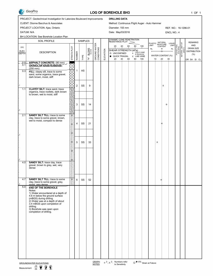
9
14
21
33
52
0.1
0.3
1.1
2.1
4.0
4.7
5.0
AS
SS
SS
SS
SS
SS
1
2
3
4
5
6
ASPHALT CONCRETE: (90 mm)GRANULAR BASE/SUBBASE:(250 mm)FILL: clayey silt, trace to somesand, some organics, trace gravel,dark brown, moist, stiff
CLAYEY SILT: trace sand, traceorganics, trace rootlets, dark brownto brown, wet to moist, stiff
SANDY SILT TILL: trace to someclay, trace to some gravel, brown,wet to moist, compact to dense
SANDY SILT: trace clay, tracegravel, brown to grey, wet, verydense
SANDY SILT TILL: trace to someclay, trace to some gravel, grey,moist, very denseEND OF THE BOREHOLE Notes:1) Water encountered at a depth of4.6 m below the ground surface(mBGS) during drilling.2) Water was at a depth of about3.4 mBGS upon completion ofdrilling.3) Borehole was open uponcompletion of drilling.
SOIL PROFILE
wL
0.0
UNCONFINED
1 OF 1
20 40 60 80 100GR
OU
ND
WA
TE
R
CO
ND
ITIO
NS
"N"
B
LOW
S
0.3
m
DESCRIPTION
PROJECT: Geotechnical Investigation for Lakeview Boulevard Improvements
CLIENT: Dionne Bacchus & Associates
PROJECT LOCATION: Ajax, Ontario
DATUM: N/A
BH LOCATION: See Borehole Location Plan
GR
REF. NO.: 16-1296-01
ENCL NO.: 4
1
2
3
4
5
Numbers referto Sensitivity
w
ELE
VA
TIO
N
:
10 20 30
REMARKS
AND
GRAIN SIZE
DISTRIBUTION
(%)
NATURALMOISTURECONTENT
3
SI
GRAPHNOTES
LIQUIDLIMIT
SAMPLES
NU
MB
ER
NA
TU
RA
L U
NIT
WT
PO
CK
ET
PE
N.PLASTIC
LIMIT
FIELD VANE& Sensitivity
ELEV
DYNAMIC CONE PENETRATIONRESISTANCE PLOT
20 40 60 80 100
QUICK TRIAXIAL
SHEAR STRENGTH (kPa)
TY
PE
,3
CL
=3%Strain at Failure
Measurement
(Cu)
(kP
a)(m)
ST
RA
TA
PLO
T
LAB VANE WATER CONTENT (%)
wP
DEPTH
SA
LOG OF BOREHOLE BH3
1st 2nd 4th3rd
GROUNDWATER ELEVATIONS
(kN
/m3 )
DRILLING DATA
Method: Continuous Flight Auger - Auto Hammer
Diameter: 155 mm
Date: May/03/2016

4
2
3
16
33
0.1
0.3
1.1
1.4
2.5
2.9
5.0
AS
SS
SS
SS
SS
SS
1
2
3
4
5
6
ASPHALT CONCRETE: (110 mm)GRANULAR BASE: (170 mm)
GRANULAR SUBBASE: (790 mm)
FILL: clayey silt, trace to somesand, some organics, trace rootlets,dark brown, wet, softFILL: sandy silt, trace to some clay,trace to some gravel, trace rootlets,trace organics, dark brown, moist towet, very loose
FILL: clayey silt, some gravel, tracesand, trace organics, dark brown,wet, soft
SANDY SILT: trace clay, somegravel, brown to grey, wet to moist,compact to dense
END OF THE BOREHOLE Notes:1) Water encountered at a depth ofabout 0.5 m below the existingground surface (mBGS) duringdrilling.2) Water was at a depth of about0.3 mBGS upon completion ofdrilling.3) Borehole caved at a depth ofabout 1.8 mBGS upon completionof drilling.4) 51 mm dia. monitoring well wasinstalled in borehole uponcompletion of drilling.
Water Level ReadingsDate W. L. Depth (mBGS)2016/05/09 2.752016/05/31 0.60
SOIL PROFILE
wL
0.0
UNCONFINED
1 OF 1
20 40 60 80 100GR
OU
ND
WA
TE
R
CO
ND
ITIO
NS
"N"
B
LOW
S
0.3
m
DESCRIPTION
PROJECT: Geotechnical Investigation for Lakeview Boulevard Improvements
CLIENT: Dionne Bacchus & Associates
PROJECT LOCATION: Ajax, Ontario
DATUM: N/A
BH LOCATION: See Borehole Location Plan
GR
REF. NO.: 16-1296-01
ENCL NO.: 5
1
2
3
4
5
Numbers referto Sensitivity
w
ELE
VA
TIO
N
:
10 20 30
REMARKS
AND
GRAIN SIZE
DISTRIBUTION
(%)
NATURALMOISTURECONTENT
3
SI
GRAPHNOTES
LIQUIDLIMIT
SAMPLES
NU
MB
ER
NA
TU
RA
L U
NIT
WT
PO
CK
ET
PE
N.PLASTIC
LIMIT
FIELD VANE& Sensitivity
ELEV
DYNAMIC CONE PENETRATIONRESISTANCE PLOT
20 40 60 80 100
QUICK TRIAXIAL
SHEAR STRENGTH (kPa)
TY
PE
,3
CL
=3%Strain at Failure
Measurement
(Cu)
(kP
a)(m)
ST
RA
TA
PLO
T
LAB VANE WATER CONTENT (%)
wP
DEPTH
SA
LOG OF BOREHOLE BH4
1st 2nd 4th3rd
GROUNDWATER ELEVATIONS
(kN
/m3 )
DRILLING DATA
Method: Continuous Flight Auger - Auto Hammer
Diameter: 155 mm
Date: May/03/2016
Concrete
Bentonite
Sand
Screen
Natural Pack
W. L. 0.6 mBGS
W. L. 2.8 mBGS

5
12
12
54
0.1
0.3
0.5
1.4
2.1
3.4
5.0
AS
AS
SS
SS
SS
SS
1
2
3
4
5
6
ASPHALT CONCRETE: (120 mm)GRANULAR BASE: (180 mm)
GRANULAR SUBBASE: (170 mm)
FILL: gravelly sand, trace to somesilt, brown, wet
FILL: clayey silt, trace to somesand, trace organics, brown, moist,firm
CLAYEY SILT TO SILTY CLAY:trace sand, trace gravel, brown,moist, stiff
SANDY SILT TILL: trace clay,trace gravel, brown to grey, moist towet, compact to very dense
---layers of silty sand
END OF THE BOREHOLE Notes:1) Water encountered at a depth of1.2 m below the ground surface(mBGS) during drilling.2) Borehole caved at a depth of 0.6mBGS upon completion of drilling.
SOIL PROFILE
wL
0.0
UNCONFINED
1 OF 1
20 40 60 80 100GR
OU
ND
WA
TE
R
CO
ND
ITIO
NS
"N"
BLO
WS
0
.3 m
DESCRIPTION
PROJECT: Geotechnical Investigation for Lakeview Boulevard Improvements
CLIENT: Dionne Bacchus & Associates
PROJECT LOCATION: Ajax, Ontario
DATUM: N/A
BH LOCATION: See Borehole Location Plan
GR
REF. NO.: 16-1296-01
ENCL NO.: 6
1
2
3
4
5
Numbers referto Sensitivity
w
ELE
VA
TIO
N
:
10 20 30
REMARKS
AND
GRAIN SIZE
DISTRIBUTION
(%)
NATURALMOISTURECONTENT
3
SI
GRAPHNOTES
LIQUIDLIMIT
SAMPLES
NU
MB
ER
NA
TU
RA
L U
NIT
WT
PO
CK
ET
PE
N.PLASTIC
LIMIT
FIELD VANE& Sensitivity
ELEV
DYNAMIC CONE PENETRATIONRESISTANCE PLOT
20 40 60 80 100
QUICK TRIAXIAL
SHEAR STRENGTH (kPa)
TY
PE
,3
CL
=3%Strain at Failure
Measurement
(Cu)
(kP
a)(m)
ST
RA
TA
PLO
T
LAB VANE WATER CONTENT (%)
wP
DEPTH
SA
LOG OF BOREHOLE BH5
1st 2nd 4th3rdGROUNDWATER ELEVATIONS
(kN
/m3)
DRILLING DATA
Method: Continuous Flight Auger - Auto Hammer
Diameter: 155 mm
Date: May/03/2016

12
15
25
39
30
0.1
0.5
0.9
5.0
AS
SS
SS
SS
SS
SS
1
2
3
4
5
6
ASPHALT CONCRETE: (125 mm)GRANULAR BASE/SUBBASE:(335 mm)
FILL: clayey silt, trace to somesand, trace gravel, brown, moist,stiff
SANDY SILT TILL TO SAND ANDSILT TILL: trace to some clay,trace to some gravel, brown to grey,wet to moist, compact to dense
END OF THE BOREHOLE Notes:1) Borehole was open and dry uponcompletion of drilling.
SOIL PROFILE
wL
0.0
UNCONFINED
1 OF 1
20 40 60 80 100GR
OU
ND
WA
TE
R
CO
ND
ITIO
NS
"N"
B
LOW
S
0.3
m
DESCRIPTION
PROJECT: Geotechnical Investigation for Lakeview Boulevard Improvements
CLIENT: Dionne Bacchus & Associates
PROJECT LOCATION: Ajax, Ontario
DATUM: N/A
BH LOCATION: See Borehole Location Plan
GR
REF. NO.: 16-1296-01
ENCL NO.: 7
1
2
3
4
5
Numbers referto Sensitivity
w
ELE
VA
TIO
N
:
10 20 30
REMARKS
AND
GRAIN SIZE
DISTRIBUTION
(%)
NATURALMOISTURECONTENT
3
SI
GRAPHNOTES
LIQUIDLIMIT
SAMPLES
NU
MB
ER
NA
TU
RA
L U
NIT
WT
PO
CK
ET
PE
N.PLASTIC
LIMIT
FIELD VANE& Sensitivity
ELEV
DYNAMIC CONE PENETRATIONRESISTANCE PLOT
20 40 60 80 100
QUICK TRIAXIAL
SHEAR STRENGTH (kPa)
TY
PE
,3
CL
=3%Strain at Failure
Measurement
(Cu)
(kP
a)(m)
ST
RA
TA
PLO
T
LAB VANE WATER CONTENT (%)
wP
DEPTH
SA
LOG OF BOREHOLE BH6
1st 2nd 4th3rd
GROUNDWATER ELEVATIONS
(kN
/m3 )
DRILLING DATA
Method: Continuous Flight Auger - Auto Hammer
Diameter: 155 mm
Date: May/03/2016

FIGURES

Project No.
DBA Town Ajax Class EA Lakeview BLVDProject Name
16-1296
Figure 1
0.0
10.0
20.0
30.0
40.0
50.0
60.0
70.0
80.0
90.0
100.0
0.001 0.01 0.1 1 10 100
PE
RC
EN
T P
AS
SIN
G
PARTICLE SIZE, mm
PARTICLE SIZE DISTRIBUTION
BH3 AS1 BH5 AS1 BH5 AS2Granular A Granular B Type 1
CLAY SILTVERY
FINE
SAND
FINE
SANDMEDIUM
SAND
COARSE
SAND
FINE
GRAVELGRAVEL
FINES (SILT & CLAY) FINE SAND MEDIUM SANDCOARSE
SANDFINE GRAVEL
COARSE
GRAVEL
SAND
COARSEMEDIUMFINE
SILTCLAY
COARSEMEDIUM
CO
BB
LE
SFINE
CO
BB
LE
S
GRAVEL
U.S.BUREAU
UNIFIED
M.I.T.

16-1296
Town of Ajax, Class EA Lakeview Boulevard
Project No.
Project Name
Figure 2
0.0
10.0
20.0
30.0
40.0
50.0
60.0
70.0
80.0
90.0
100.0
0.001 0.01 0.1 1 10 100
PE
RC
EN
T P
AS
SIN
G
GRAIN SIZE, mm
GRAIN SIZE DISTRIBUTION
BH1 SS3 BH6 SS4
CLAY SILTVERY
FINE
SAND
FINE
SANDMEDIUM
SAND
COARSE
SAND
FINE
GRAVELGRAVEL
FINES (SILT & CLAY) FINE SAND MEDIUM SANDCOARSE
SANDFINE GRAVEL
COARSE
GRAVEL
SAND
COARSEMEDIUMFINE
SILTCLAY
COARSEMEDIUM
CO
BB
LE
SFINE
CO
BB
LE
S
GRAVEL
U.S.BUREAU
UNIFIED
M.I.T.

Project: Client:
Sample ID:
16-1296 Town of Ajax
1296SA20160503
Figure 3
Plastic Limit
Liquid Limit
Plastic Index
BH5 SS4
18.7
46.4
27.7
ATTERBURG LIMIT
MTO LS-703/704
Lakeview BoulevardProject/Location:
Atterburg Limit, %
0
10
20
30
40
50
60
0 10 20 30 40 50 60 70 80 90 100
Pla
stic
ity
Ind
ex %
Liquid Limit %
Atterburg Limit
BH5 SS4
CL
ML or OL
CH
OH or MH
CL-ML
ML

Unit 25 to 27, 40 Vogell Road, Richmond Hill, Ontario L4B 3N6 Tel: 905 237 8336 Fax: 905 248 3699 www.geoproconsulting.ca
LIMITATIONS TO THE REPORT
This report is intended solely for the Client named. The report is prepared based on the work has been undertaken in accordance with normally accepted geotechnical engineering practices in Ontario.
The comments and recommendations given in this report are based on information determined at the limited number of the test hole and test pit locations. The boundaries between the various strata as shown on the borehole logs are based on non-continuous sampling and represent an inferred transition between the various strata and their lateral continuation rather than a precise plane of geological change. Subsurface and groundwater conditions between and beyond the test holes and test pits may differ significantly from those encountered at the test hole and test pit locations. The benchmark and elevations used in this report are primarily to establish relative elevation differences between the test hole and test pit locations and should not be used for other purposes, such as grading, excavating, planning, development, etc.
The report reflects our best judgment based on the information available to GeoPro Consulting Limited at the time of preparation. Unless otherwise agreed in writing by GeoPro Consulting Limited, it shall not be used to express or imply warranty as to any other purposes. No portion of this report shall be used as a separate entity, it is written to be read in its entirety. The information contained herein in no way reflects on the environment aspects of the project, unless otherwise stated.
The design recommendations given in this report are applicable only to the project designed and constructed completely in accordance with the details stated in this report.
Should any comments and recommendations provided in this report be made on any construction related issues, they are intended only for the guidance of the designers. The number of test holes and test pits may not be sufficient to determine all the factors that may affect construction activities, methods and costs. Such as, the thickness of surficial topsoil or fill layers may vary significantly and unpredictably; the amount of the cobbles and boulders may vary significantly than what described in the report; unexpected water bearing zones/layers with various thickness and extent may be encountered in the fill and native soils. The contractors bidding on this project or undertaking the construction should, therefore, make their own interpretation of the factual information presented and make their own conclusions as to how the subsurface conditions may affect their work and determine the proper construction methods.
Any use which a third party makes of this report, or any reliance on or decisions to be made based on it, are the responsibility of such third parties. GeoPro Consulting Limited accepts no responsibility for damages, if any, suffered by any third party as a result of decisions made or actions based on this report.
We accept no responsibility for any decisions made or actions taken as a result of this report unless we are specifically advised of and participate in such action, in which case our responsibility will be as agreed to at that time.