Embed Size (px)
Citation preview
American Institute of Aeronautics and Astronautics
092407
1
Preliminary Findings from the SHERE ISS Experiment
Nancy R. Hall1 NASA Glenn Research Center, Cleveland, OH 44135
Gareth H. McKinley2, Philipp Erni3 and Johannes Soulages4 Massachusetts Institute of Technology, Cambridge, MA 02139
and
Kevin S. Magee5 ZIN Technologies Inc, Middleburg Heights, OH 44130
The Shear History Extensional Rheology Experiment (SHERE) is an International Space Station (ISS) glovebox experiment designed to study the effect of preshear on the transient evolution of the microstructure and viscoelastic tensile stresses for monodisperse dilute polymer solutions. The SHERE experiment hardware was launched on Shuttle Mission STS-120 (ISS Flight 10A) on October 22, 2007, and 20 fluid samples were launched on Shuttle Mission STS-123 (ISS Flight 1J/A) on March 11, 2008. Astronaut Gregory Chamitoff performed experiments during Increment 17 on the ISS between June and September 2008. A summary of the ten year history of the hardware development, the experiment’s science objectives, and Increment 17’s flight operations are discussed in the paper. A brief summary of the preliminary science results is also discussed.
Nomenclature D = displacement ε = Hencky strain !& = extensional strain rate F = force g = gravity Lo = initial length Ro = initial radius Rmid = midpoint diameter T = temperature t = time V(t) = stretch velocity Vf = final stretch velocity Ω = pre-rotation (pre-shear) rate µ = viscosity
1 Project Manager, Space Processes and Experiments Division, 21000 Brookpark Road, AIAA Senior Member. 2 Principal Investigator, Department of Mechanical Engineering, 77 Massachusetts Avenue, and non-member. 3 SHERE Scientist, Department of Mechanical Engineering, 77 Massachusetts Avenue, and non-member 4 SHERE Scientist, Department of Mechanical Engineering, 77 Massachusetts Avenue, and non-member 5 Lead Engineer, 6745 Engle Road, AIAA Senior Member.
https://ntrs.nasa.gov/search.jsp?R=20120012837 2018-06-04T06:50:02+00:00Z
American Institute of Aeronautics and Astronautics
092407
2
I. Introduction On October 22, 2007, the Shear History Extensional Rheology Experiment (SHERE) hardware, consisting of the Rheometer, Camera Arm, Interface Box, Keyboard, Tool Box, and cabling, was launched inside the Harmony (Node 2) on Space Shuttle Mission STS-120 (ISS Flight 10A). Then on March 11, 2008, twenty fluid modules housed inside their Stowage Tray were launched on Space Shuttle Mission STS-123 (ISS Flight 1J/A). These launches were a culmination of over 10 years of perseverance on the part of the science and engineering team who had been working on the SHERE project at NASA Glenn Research Center. The project started in 1998 with the submission of a glovebox investigation proposal1 by Principal Investigator (PI) Gareth H. McKinley. One of the goals in the proposal was to design a microgravity glovebox experiment to study “the pre-shear history of the transient extensional viscosity in a uniaxial stretching flow for dilute polymer solutions together with the subsequent relaxation behavior after cessation of extensional deformation.” Since that time the project team worked to design, fabricate, build, test, and eventually deliver the SHERE hardware for launch to the ISS while overcoming many obstacles that impeded the team’s progress. For example, with the launch of the Microgravity Science Glovebox (MSG) facility to ISS in 2002, the experiment was redesign and modified to fit inside this new facility instead of the originally envisioned Microgravity Glovebox (MGBX) facility on the Space Shuttle. This turned out to be a benefit to the project as it allowed more room and capability for the hardware. As NASA’s focus in the area of fundamental science research changed, the project was also canceled and reinstated twice during its 10 years of development. However, one key facet that has allowed this project to continue is its relevance in fundamental science for both polymer processing operations on Earth and in-situ fabrication of polymer parts in space exploration, although currently its key focus is on Earth applications.
II. Science Objectives The combination of both rotational shearing and extensional stretching flows is common in many polymer-
processing operations such as extrusion, blow-molding, and fiber spinning. Therefore, knowledge of the complete rheological properties of a polymeric fluid being processed is required in order to accurately predict and account for its total flow behavior. If numerical simulations are to serve as a priori design tools for optimizing polymer processing operations, then it is critical to have an accurate knowledge of the extensional viscosity and its variation with temperature, concentration, molecular weight, and strain rate.
Unlike Newtonian fluids, complex fluids such as polymers cannot be characterized by a single linear material parameter such as the Newtonian viscosity, µ. Instead, they exhibit a non-linear response to imposed deformations. Constitutive models have shown the extensional function of a non-Newtonian fluid is not constant but depends on both the rate of deformation and the total strain experienced by a fluid element. 2
A class of dilute polymer solutions collectively referred to as “Boger fluids” has become a popular choice for rheological studies of non-Newtonian fluids and is used in this experiment. This ideal elastic fluid exhibits a nearly constant shear viscosity that allows a direct comparison of Boger fluids with Newtonian fluids having similar viscosities. The high viscosity of the suspending solvent, which results in long relaxation times and substantial normal stresses, and the low concentration of high molecular weight polymers dissolved in the suspending solvent, which give rise to elasticity and substantial normal stresses, both facilitate modeling analysis. 3
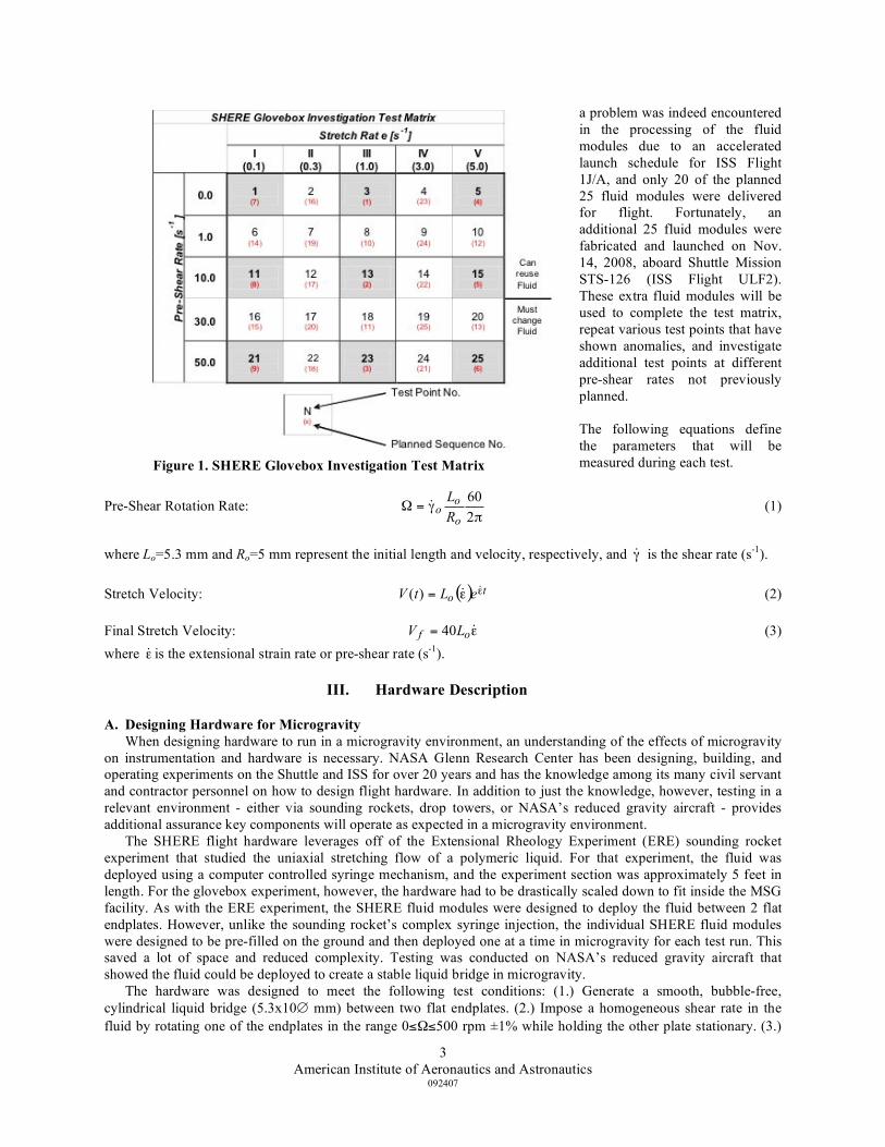
The SHERE flight experiment leverages off of the Extensional Rheology Experiment (ERE) sounding rocket experiment in the 1990’s that studied the uniaxial stretching flow of a polymeric liquid. ERE only studied axial stretching, however, and did not incorporate rotational shearing into its design. Due to the vorticity and shearing deformation induced by the rotational shear flow on the polymer chains, rotational shearing of the fluid immediately before uniaxial extension will have an effect on the extensional behavior of the fluid. In effect, the fluid has a “memory” of the strains previously encountered beforehand. The SHERE glovebox investigation was designed with 25 test points as defined in Fig. 1 and combines both rotational shearing and uniaxial extension into the test matrix. These 25 test points consist of 5 series of tests with different stretch rates from slow (I) to fast (V). Within each stretch rate, there are 5 different rotational pre-shear rates ranging from 0 to 500 rpm. The tests in the matrix are identified in two ways. The first identifies the 1 through 25 test point number, which describes the combination of rotational pre-shear and extensional rates. The second identifies the planned sequence that the tests are to be operated on board the ISS according to priority. This priority is identified in smaller print in parentheses below each test point number. This ordering allows an optimization of test points spanning the low, moderate, and high stretch rates along with the slow, moderate, and fast pre-shear rates. The shaded squares represent the minimum test points required for minimum science return while all 25 test point are required for complete science return. This prioritization allows minimum science to be achieved even in the event of a problem that prevents full testing. Such
American Institute of Aeronautics and Astronautics
092407
3
a problem was indeed encountered in the processing of the fluid modules due to an accelerated launch schedule for ISS Flight 1J/A, and only 20 of the planned 25 fluid modules were delivered for flight. Fortunately, an additional 25 fluid modules were fabricated and launched on Nov. 14, 2008, aboard Shuttle Mission STS-126 (ISS Flight ULF2). These extra fluid modules will be used to complete the test matrix, repeat various test points that have shown anomalies, and investigate additional test points at different pre-shear rates not previously planned. The following equations define the parameters that will be measured during each test.
Pre-Shear Rotation Rate: !
"=#2
60
o
ooR
L& (1)
where Lo=5.3 mm and Ro=5 mm represent the initial length and velocity, respectively, and !& is the shear rate (s-1). Stretch Velocity: ( ) t
o eLtV !!= &&)( (2) Final Stretch Velocity: != &of LV 40 (3) where !& is the extensional strain rate or pre-shear rate (s-1).
III. Hardware Description
A. Designing Hardware for Microgravity When designing hardware to run in a microgravity environment, an understanding of the effects of microgravity
on instrumentation and hardware is necessary. NASA Glenn Research Center has been designing, building, and operating experiments on the Shuttle and ISS for over 20 years and has the knowledge among its many civil servant and contractor personnel on how to design flight hardware. In addition to just the knowledge, however, testing in a relevant environment - either via sounding rockets, drop towers, or NASA’s reduced gravity aircraft - provides additional assurance key components will operate as expected in a microgravity environment.
The SHERE flight hardware leverages off of the Extensional Rheology Experiment (ERE) sounding rocket experiment that studied the uniaxial stretching flow of a polymeric liquid. For that experiment, the fluid was deployed using a computer controlled syringe mechanism, and the experiment section was approximately 5 feet in length. For the glovebox experiment, however, the hardware had to be drastically scaled down to fit inside the MSG facility. As with the ERE experiment, the SHERE fluid modules were designed to deploy the fluid between 2 flat endplates. However, unlike the sounding rocket’s complex syringe injection, the individual SHERE fluid modules were designed to be pre-filled on the ground and then deployed one at a time in microgravity for each test run. This saved a lot of space and reduced complexity. Testing was conducted on NASA’s reduced gravity aircraft that showed the fluid could be deployed to create a stable liquid bridge in microgravity.
The hardware was designed to meet the following test conditions: (1.) Generate a smooth, bubble-free, cylindrical liquid bridge (5.3x10∅ mm) between two flat endplates. (2.) Impose a homogeneous shear rate in the fluid by rotating one of the endplates in the range 0≤Ω≤500 rpm ±1% while holding the other plate stationary. (3.)
Figure 1. SHERE Glovebox Investigation Test Matrix
American Institute of Aeronautics and Astronautics
092407
4
Achieve target angular velocity within 100 ms; and stop rotation within 10 ms of starting elongational deformation. (4.) Impose an approximately homogeneous elongational deformation in the fluid by axially translating one endplate in an exponential manner to generate strain rates ( !& ) in the range 0.1≤ !& ≤5.0 s-1 while obtaining maximum Hencky strains in the range 3.5≤ε≤4.5. (5.) Conduct all tests within the temperature range 20≤T≤25 °C (68≤T≤77 °F).
The following measurement requirements were imposed on the hardware design: (1.) Measure the axial force induced due to shearing and stretching within the range of |F|≤104dyne ± 50 dyne (10 ± 0.05 grams-force). (2.) Measure the actual axial elongation of the fluid to within ± 0.05 mm. (3.) Measure the axial midplane diameter of fluid filament within the range of 0.1≤D≤10 mm ± 0.005 mm. (4.) Measure the temperature T of the fluid to within ± (0.5) °C. (5.) Provide video of the fluid filament to detect edges and measure axial profile D(z) of the fluid column.
The above test conditions and measurement requirements were the requirements that served as the basis for the design of the SHERE experiment hardware. This resulted in the current hardware configuration that consists of the SHERE Rheometer, Camera Arm, Interface Box, Keyboard, Tool Box, Fluid Modules, Stowage Tray, and cabling., However, during the course of the hardware development and science verification testing, whenever a certain requirement was not clearly able to be met, discussions and/or analysis were provided to the Principal Investigator to either relax the requirement or require a change to the overall hardware design to ensure that the requirement was met.
The flight hardware for SHERE, along with an identical engineering unit used for training astronauts and ground-based testing, were designed and built by ZIN Technologies, Inc. A brief description of each SHERE equipment item follows, and operations in microgravity are discussed later.
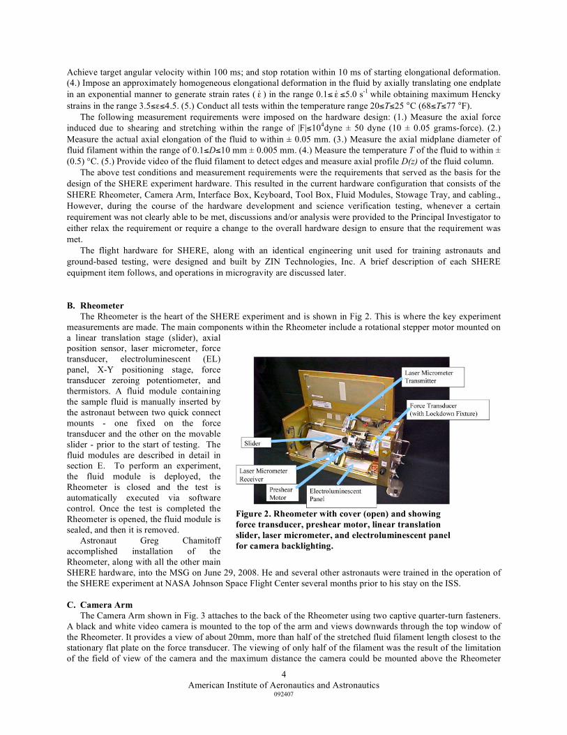
B. Rheometer The Rheometer is the heart of the SHERE experiment and is shown in Fig 2. This is where the key experiment
measurements are made. The main components within the Rheometer include a rotational stepper motor mounted on a linear translation stage (slider), axial position sensor, laser micrometer, force transducer, electroluminescent (EL) panel, X-Y positioning stage, force transducer zeroing potentiometer, and thermistors. A fluid module containing the sample fluid is manually inserted by the astronaut between two quick connect mounts - one fixed on the force transducer and the other on the movable slider - prior to the start of testing. The fluid modules are described in detail in section E. To perform an experiment, the fluid module is deployed, the Rheometer is closed and the test is automatically executed via software control. Once the test is completed the Rheometer is opened, the fluid module is sealed, and then it is removed.
Astronaut Greg Chamitoff accomplished installation of the Rheometer, along with all the other main SHERE hardware, into the MSG on June 29, 2008. He and several other astronauts were trained in the operation of the SHERE experiment at NASA Johnson Space Flight Center several months prior to his stay on the ISS.
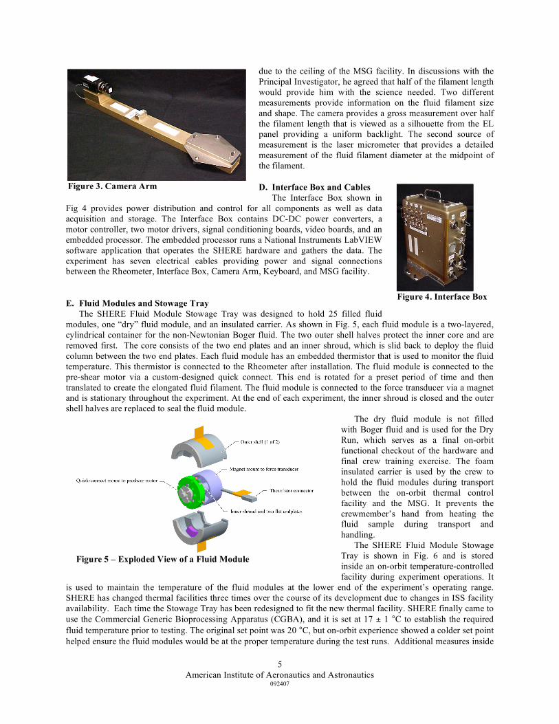
C. Camera Arm The Camera Arm shown in Fig. 3 attaches to the back of the Rheometer using two captive quarter-turn fasteners.
A black and white video camera is mounted to the top of the arm and views downwards through the top window of the Rheometer. It provides a view of about 20mm, more than half of the stretched fluid filament length closest to the stationary flat plate on the force transducer. The viewing of only half of the filament was the result of the limitation of the field of view of the camera and the maximum distance the camera could be mounted above the Rheometer
Figure 2. Rheometer with cover (open) and showing force transducer, preshear motor, linear translation slider, laser micrometer, and electroluminescent panel for camera backlighting.
American Institute of Aeronautics and Astronautics
092407
5
due to the ceiling of the MSG facility. In discussions with the Principal Investigator, he agreed that half of the filament length would provide him with the science needed. Two different measurements provide information on the fluid filament size and shape. The camera provides a gross measurement over half the filament length that is viewed as a silhouette from the EL panel providing a uniform backlight. The second source of measurement is the laser micrometer that provides a detailed measurement of the fluid filament diameter at the midpoint of the filament.
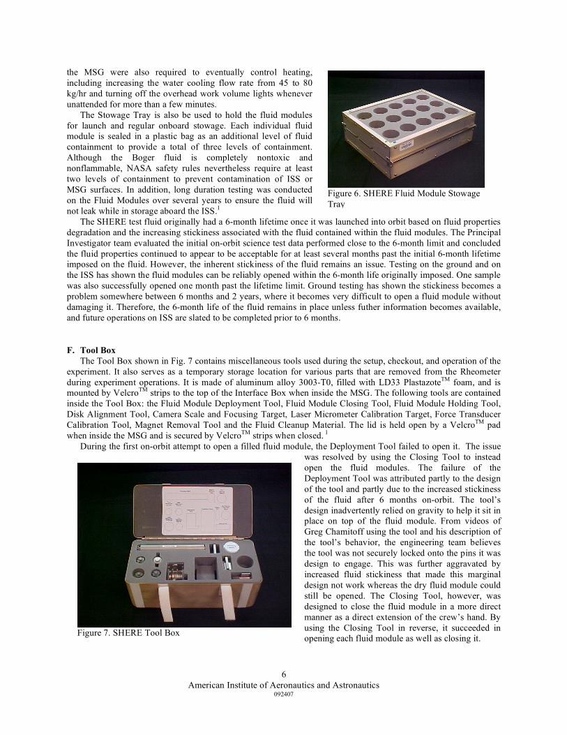
D. Interface Box and Cables The Interface Box shown in
Fig 4 provides power distribution and control for all components as well as data acquisition and storage. The Interface Box contains DC-DC power converters, a motor controller, two motor drivers, signal conditioning boards, video boards, and an embedded processor. The embedded processor runs a National Instruments LabVIEW software application that operates the SHERE hardware and gathers the data. The experiment has seven electrical cables providing power and signal connections between the Rheometer, Interface Box, Camera Arm, Keyboard, and MSG facility.
E. Fluid Modules and Stowage Tray The SHERE Fluid Module Stowage Tray was designed to hold 25 filled fluid
modules, one “dry” fluid module, and an insulated carrier. As shown in Fig. 5, each fluid module is a two-layered, cylindrical container for the non-Newtonian Boger fluid. The two outer shell halves protect the inner core and are removed first. The core consists of the two end plates and an inner shroud, which is slid back to deploy the fluid column between the two end plates. Each fluid module has an embedded thermistor that is used to monitor the fluid temperature. This thermistor is connected to the Rheometer after installation. The fluid module is connected to the pre-shear motor via a custom-designed quick connect. This end is rotated for a preset period of time and then translated to create the elongated fluid filament. The fluid module is connected to the force transducer via a magnet and is stationary throughout the experiment. At the end of each experiment, the inner shroud is closed and the outer shell halves are replaced to seal the fluid module.
The dry fluid module is not filled with Boger fluid and is used for the Dry Run, which serves as a final on-orbit functional checkout of the hardware and final crew training exercise. The foam insulated carrier is used by the crew to hold the fluid modules during transport between the on-orbit thermal control facility and the MSG. It prevents the crewmember’s hand from heating the fluid sample during transport and handling.
The SHERE Fluid Module Stowage Tray is shown in Fig. 6 and is stored inside an on-orbit temperature-controlled facility during experiment operations. It
is used to maintain the temperature of the fluid modules at the lower end of the experiment’s operating range. SHERE has changed thermal facilities three times over the course of its development due to changes in ISS facility availability. Each time the Stowage Tray has been redesigned to fit the new thermal facility. SHERE finally came to use the Commercial Generic Bioprocessing Apparatus (CGBA), and it is set at 17 ± 1 °C to establish the required fluid temperature prior to testing. The original set point was 20 °C, but on-orbit experience showed a colder set point helped ensure the fluid modules would be at the proper temperature during the test runs. Additional measures inside
Figure 4. Interface Box
Figure 5 – Exploded View of a Fluid Module
Figure 3. Camera Arm
American Institute of Aeronautics and Astronautics
092407
6
the MSG were also required to eventually control heating, including increasing the water cooling flow rate from 45 to 80 kg/hr and turning off the overhead work volume lights whenever unattended for more than a few minutes.
The Stowage Tray is also be used to hold the fluid modules for launch and regular onboard stowage. Each individual fluid module is sealed in a plastic bag as an additional level of fluid containment to provide a total of three levels of containment. Although the Boger fluid is completely nontoxic and nonflammable, NASA safety rules nevertheless require at least two levels of containment to prevent contamination of ISS or MSG surfaces. In addition, long duration testing was conducted on the Fluid Modules over several years to ensure the fluid will not leak while in storage aboard the ISS.1
The SHERE test fluid originally had a 6-month lifetime once it was launched into orbit based on fluid properties degradation and the increasing stickiness associated with the fluid contained within the fluid modules. The Principal Investigator team evaluated the initial on-orbit science test data performed close to the 6-month limit and concluded the fluid properties continued to appear to be acceptable for at least several months past the initial 6-month lifetime imposed on the fluid. However, the inherent stickiness of the fluid remains an issue. Testing on the ground and on the ISS has shown the fluid modules can be reliably opened within the 6-month life originally imposed. One sample was also successfully opened one month past the lifetime limit. Ground testing has shown the stickiness becomes a problem somewhere between 6 months and 2 years, where it becomes very difficult to open a fluid module without damaging it. Therefore, the 6-month life of the fluid remains in place unless futher information becomes available, and future operations on ISS are slated to be completed prior to 6 months.
F. Tool Box The Tool Box shown in Fig. 7 contains miscellaneous tools used during the setup, checkout, and operation of the
experiment. It also serves as a temporary storage location for various parts that are removed from the Rheometer during experiment operations. It is made of aluminum alloy 3003-T0, filled with LD33 PlastazoteTM foam, and is mounted by VelcroTM strips to the top of the Interface Box when inside the MSG. The following tools are contained inside the Tool Box: the Fluid Module Deployment Tool, Fluid Module Closing Tool, Fluid Module Holding Tool, Disk Alignment Tool, Camera Scale and Focusing Target, Laser Micrometer Calibration Target, Force Transducer Calibration Tool, Magnet Removal Tool and the Fluid Cleanup Material. The lid is held open by a VelcroTM pad when inside the MSG and is secured by VelcroTM strips when closed. 1
During the first on-orbit attempt to open a filled fluid module, the Deployment Tool failed to open it. The issue was resolved by using the Closing Tool to instead open the fluid modules. The failure of the Deployment Tool was attributed partly to the design of the tool and partly due to the increased stickiness of the fluid after 6 months on-orbit. The tool’s design inadvertently relied on gravity to help it sit in place on top of the fluid module. From videos of Greg Chamitoff using the tool and his description of the tool’s behavior, the engineering team believes the tool was not securely locked onto the pins it was design to engage. This was further aggravated by increased fluid stickiness that made this marginal design not work whereas the dry fluid module could still be opened. The Closing Tool, however, was designed to close the fluid module in a more direct manner as a direct extension of the crew’s hand. By using the Closing Tool in reverse, it succeeded in opening each fluid module as well as closing it.
Figure 6. SHERE Fluid Module Stowage Tray
Figure 7. SHERE Tool Box
American Institute of Aeronautics and Astronautics
092407
7
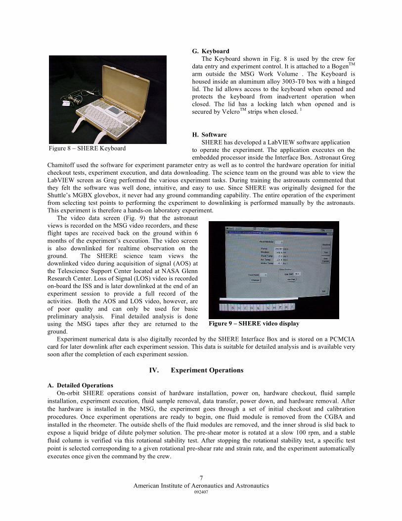
G. Keyboard The Keyboard shown in Fig. 8 is used by the crew for
data entry and experiment control. It is attached to a BogenTM arm outside the MSG Work Volume . The Keyboard is housed inside an aluminum alloy 3003-T0 box with a hinged lid. The lid allows access to the keyboard when opened and protects the keyboard from inadvertent operation when closed. The lid has a locking latch when opened and is secured by VelcroTM strips when closed. 1
H. Software SHERE has developed a LabVIEW software application
to operate the experiment. The application executes on the embedded processor inside the Interface Box. Astronaut Greg
Chamitoff used the software for experiment parameter entry as well as to control the hardware operation for initial checkout tests, experiment execution, and data downloading. The science team on the ground was able to view the LabVIEW screen as Greg performed the various experiment tasks. During training the astronauts commented that they felt the software was well done, intuitive, and easy to use. Since SHERE was originally designed for the Shuttle’s MGBX glovebox, it never had any ground commanding capability. The entire operation of the experiment from selecting test points to performing the experiment to downlinking is performed manually by the astronauts. This experiment is therefore a hands-on laboratory experiment.
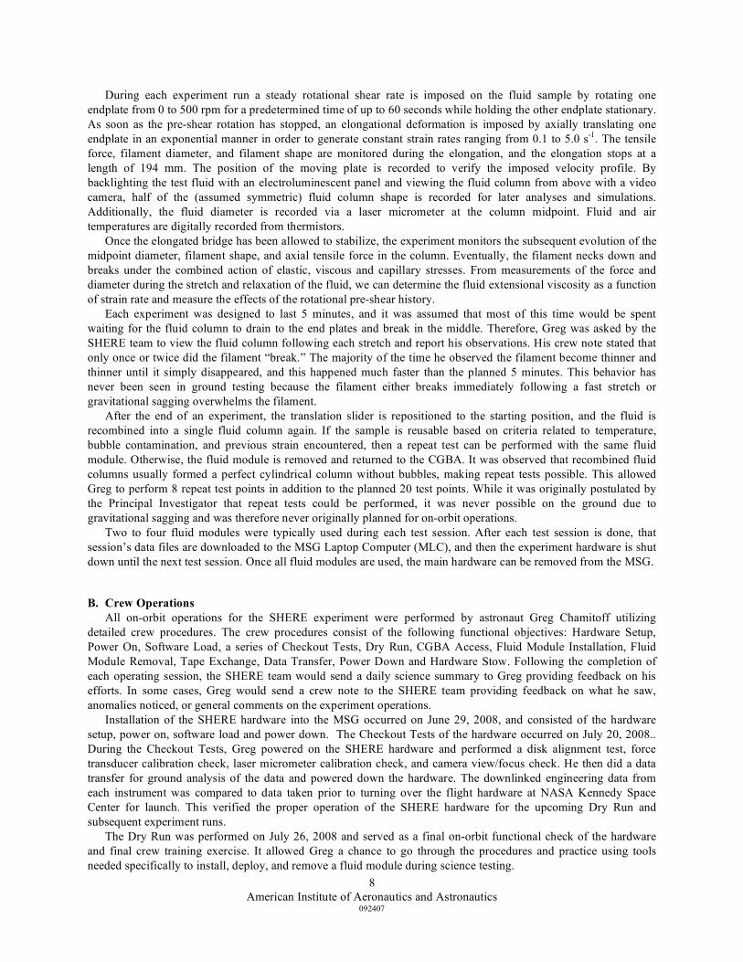
The video data screen (Fig. 9) that the astronaut views is recorded on the MSG video recorders, and these flight tapes are received back on the ground within 6 months of the experiment’s execution. The video screen is also downlinked for realtime observation on the ground. The SHERE science team views the downlinked video during acquisition of signal (AOS) at the Telescience Support Center located at NASA Glenn Research Center. Loss of Signal (LOS) video is recorded on-board the ISS and is later downlinked at the end of an experiment session to provide a full record of the activities. Both the AOS and LOS video, however, are of poor quality and can only be used for basic preliminary analysis. Final detailed analysis is done using the MSG tapes after they are returned to the ground.
Experiment numerical data is also digitally recorded by the SHERE Interface Box and is stored on a PCMCIA card for later downlink after each experiment session. This data is suitable for detailed analysis and is available very soon after the completion of each experiment session.
IV. Experiment Operations
A. Detailed Operations On-orbit SHERE operations consist of hardware installation, power on, hardware checkout, fluid sample
installation, experiment execution, fluid sample removal, data transfer, power down, and hardware removal. After the hardware is installed in the MSG, the experiment goes through a set of initial checkout and calibration procedures. Once experiment operations are ready to begin, one fluid module is removed from the CGBA and installed in the rheometer. The outside shells of the fluid modules are removed, and the inner shroud is slid back to expose a liquid bridge of dilute polymer solution. The pre-shear motor is rotated at a slow 100 rpm, and a stable fluid column is verified via this rotational stability test. After stopping the rotational stability test, a specific test point is selected corresponding to a given rotational pre-shear rate and strain rate, and the experiment automatically executes once given the command by the crew.
Figure 8 – SHERE Keyboard
Figure 9 – SHERE video display
American Institute of Aeronautics and Astronautics
092407
8
During each experiment run a steady rotational shear rate is imposed on the fluid sample by rotating one endplate from 0 to 500 rpm for a predetermined time of up to 60 seconds while holding the other endplate stationary. As soon as the pre-shear rotation has stopped, an elongational deformation is imposed by axially translating one endplate in an exponential manner in order to generate constant strain rates ranging from 0.1 to 5.0 s-1. The tensile force, filament diameter, and filament shape are monitored during the elongation, and the elongation stops at a length of 194 mm. The position of the moving plate is recorded to verify the imposed velocity profile. By backlighting the test fluid with an electroluminescent panel and viewing the fluid column from above with a video camera, half of the (assumed symmetric) fluid column shape is recorded for later analyses and simulations. Additionally, the fluid diameter is recorded via a laser micrometer at the column midpoint. Fluid and air temperatures are digitally recorded from thermistors.
Once the elongated bridge has been allowed to stabilize, the experiment monitors the subsequent evolution of the midpoint diameter, filament shape, and axial tensile force in the column. Eventually, the filament necks down and breaks under the combined action of elastic, viscous and capillary stresses. From measurements of the force and diameter during the stretch and relaxation of the fluid, we can determine the fluid extensional viscosity as a function of strain rate and measure the effects of the rotational pre-shear history.
Each experiment was designed to last 5 minutes, and it was assumed that most of this time would be spent waiting for the fluid column to drain to the end plates and break in the middle. Therefore, Greg was asked by the SHERE team to view the fluid column following each stretch and report his observations. His crew note stated that only once or twice did the filament “break.” The majority of the time he observed the filament become thinner and thinner until it simply disappeared, and this happened much faster than the planned 5 minutes. This behavior has never been seen in ground testing because the filament either breaks immediately following a fast stretch or gravitational sagging overwhelms the filament.
After the end of an experiment, the translation slider is repositioned to the starting position, and the fluid is recombined into a single fluid column again. If the sample is reusable based on criteria related to temperature, bubble contamination, and previous strain encountered, then a repeat test can be performed with the same fluid module. Otherwise, the fluid module is removed and returned to the CGBA. It was observed that recombined fluid columns usually formed a perfect cylindrical column without bubbles, making repeat tests possible. This allowed Greg to perform 8 repeat test points in addition to the planned 20 test points. While it was originally postulated by the Principal Investigator that repeat tests could be performed, it was never possible on the ground due to gravitational sagging and was therefore never originally planned for on-orbit operations.
Two to four fluid modules were typically used during each test session. After each test session is done, that session’s data files are downloaded to the MSG Laptop Computer (MLC), and then the experiment hardware is shut down until the next test session. Once all fluid modules are used, the main hardware can be removed from the MSG.
B. Crew Operations All on-orbit operations for the SHERE experiment were performed by astronaut Greg Chamitoff utilizing
detailed crew procedures. The crew procedures consist of the following functional objectives: Hardware Setup, Power On, Software Load, a series of Checkout Tests, Dry Run, CGBA Access, Fluid Module Installation, Fluid Module Removal, Tape Exchange, Data Transfer, Power Down and Hardware Stow. Following the completion of each operating session, the SHERE team would send a daily science summary to Greg providing feedback on his efforts. In some cases, Greg would send a crew note to the SHERE team providing feedback on what he saw, anomalies noticed, or general comments on the experiment operations.
Installation of the SHERE hardware into the MSG occurred on June 29, 2008, and consisted of the hardware setup, power on, software load and power down. The Checkout Tests of the hardware occurred on July 20, 2008.. During the Checkout Tests, Greg powered on the SHERE hardware and performed a disk alignment test, force transducer calibration check, laser micrometer calibration check, and camera view/focus check. He then did a data transfer for ground analysis of the data and powered down the hardware. The downlinked engineering data from each instrument was compared to data taken prior to turning over the flight hardware at NASA Kennedy Space Center for launch. This verified the proper operation of the SHERE hardware for the upcoming Dry Run and subsequent experiment runs.
The Dry Run was performed on July 26, 2008 and served as a final on-orbit functional check of the hardware and final crew training exercise. It allowed Greg a chance to go through the procedures and practice using tools needed specifically to install, deploy, and remove a fluid module during science testing.
American Institute of Aeronautics and Astronautics
092407
9
The first experiment run was attempted on July 31, 2008, and as mentioned previously, the Deployment Tool failed to open the fluid module due to problems with the tool’s design and the stickiness of the fluid. On August 2, 2008, a second attempt was made to deploy a fluid module using the Closing Tool instead of the Deployment Tool, and this resulted in a successful deployment and test of the fluid module. A total of two test points from the test matrix were successfully completed during this first operating session.
Between August 2 and September 30 all twenty fluid modules were used to obtain twenty test points from the test matrix. In addition, eight repeat test points were completed by Greg. These repeat tests were made possible by recombining the fluid column after the first test run and performing a second test using the same fluid module. This was originally not thought to be possible due to concerns about bubble inclusion and how a recombined fluid column would appear, but on-orbit experience showed it was quite possible and desirable for low extensional strain rate tests.
It should be noted almost all of SHERE’s science sessions were the result of Voluntary Science performed by Greg. Voluntary Science is an opportunity to obtain additional science above the planned hard-scheduled operating sessions. It is performed on non-operating days such as weekends and holidays that would normally be scheduled as the astronaut’s free time. Instead of taking a break, the crew can choose to perform other activities during their free time if they wish. Greg repeatedly chose SHERE on his days off in order to complete the experiment before the lifetime of the experiment fluid expired, and without this, it would have been impossible to complete the experiment in the allocated period of time. SHERE owes a great debt to Greg for doing this.
V. Preliminary Science Summary The following contain preliminary science data plots performed by the SHERE PI team and comments on the
initial test points performed on the SHERE flight hardware. This data was also submitted to Greg Chamitoff to show him preliminary results as the test points he had run for the SHERE team. While data plots after each science run can be produced, the analysis is more meaningful when runs with different stretch rates can be compared. That involves looking both at the time at which the stretch starts and the time at which the stretch ends, after which the
diameter decays but the fluid is no longer stretched. By non-dimensionalizing the time data with the stretch rate; this ultimately allows comparison data at different stretch rates. The data also need to be filtered appropriately to eliminate instrument noise. To turn this into rheology, we further need to convert the force data into extensional stresses based on the filament stretching force balance.
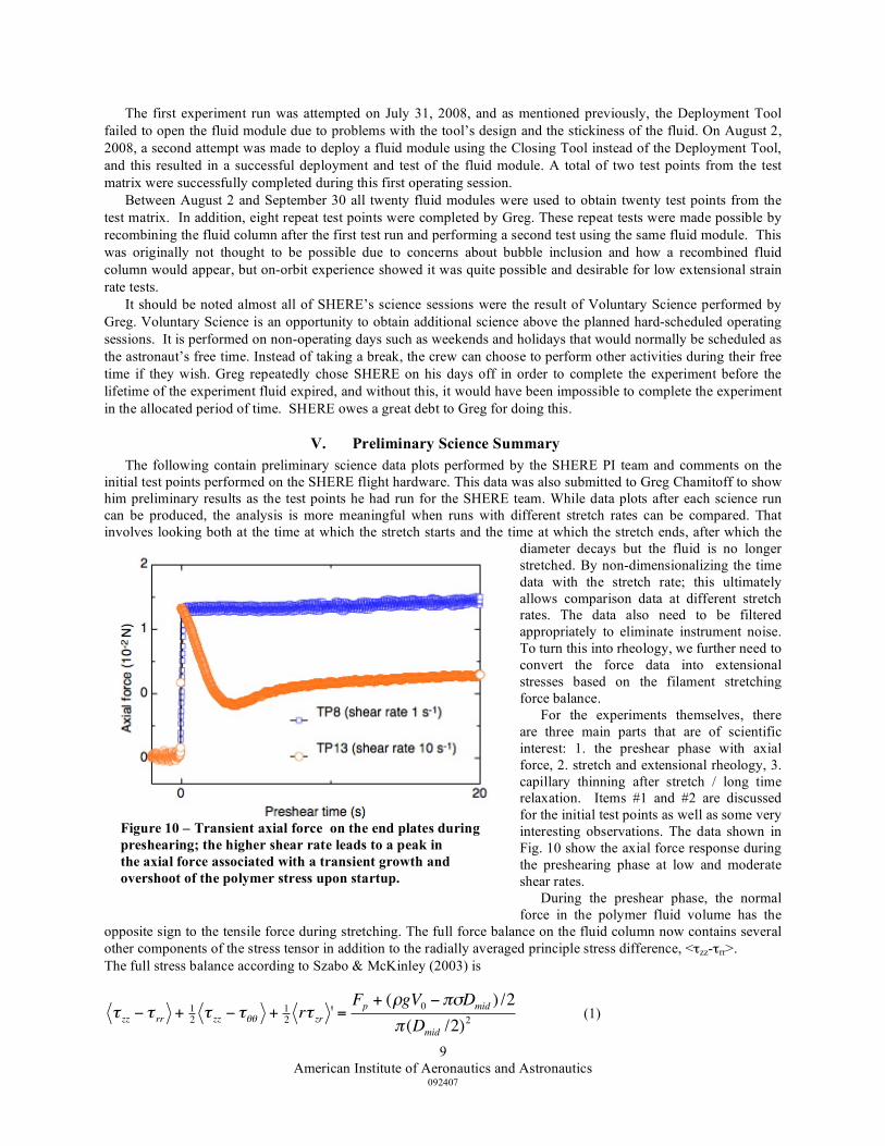
For the experiments themselves, there are three main parts that are of scientific interest: 1. the preshear phase with axial force, 2. stretch and extensional rheology, 3. capillary thinning after stretch / long time relaxation. Items #1 and #2 are discussed for the initial test points as well as some very interesting observations. The data shown in Fig. 10 show the axial force response during the preshearing phase at low and moderate shear rates. During the preshear phase, the normal force in the polymer fluid volume has the
opposite sign to the tensile force during stretching. The full force balance on the fluid column now contains several other components of the stress tensor in addition to the radially averaged principle stress difference, <τzz-τrr>. The full stress balance according to Szabo & McKinley (2003) is
!
" zz # " rr + 1
2" zz # "$$ + 1
2r" zr ' =
Fp + (%gV0#&'Dmid ) /2
& (Dmid /2)2
(1)
Figure 10 – Transient axial force on the end plates during preshearing; the higher shear rate leads to a peak in the axial force associated with a transient growth and overshoot of the polymer stress upon startup.
American Institute of Aeronautics and Astronautics
092407
10
where < > is a radially averaged quantity, the prime indicates an axial derivative, V0 is the volume of the fluid sample, s is the surface tension of the fluid, and r is its density.
Figure 11 shows Test points 11, 13, 15 with different stretch rates 0.1, 1, and 5 s-1 and with an identical preshear rate of 10 s-1. The time axis after the stretch begins is made dimensionless with the stretch rate of each test (this dimensionless time can also be considered as an apparent Hencky strain). This representation allows the comparison of experiments performed at different stretch rates. Plotted on a linear time axis, the three runs span a range of experimental time scales of almost two orders of magnitude. At all extensional rates, an initial growth in the axial force is seen, which is typical for polymer solutions. The total stress (or axial force) increases dramatically for the faster rates. Additionally, the strain-hardening
secondary peak can be seen to increase at faster stretch rates. This is due to the large molecular weight polymers being stretched out.
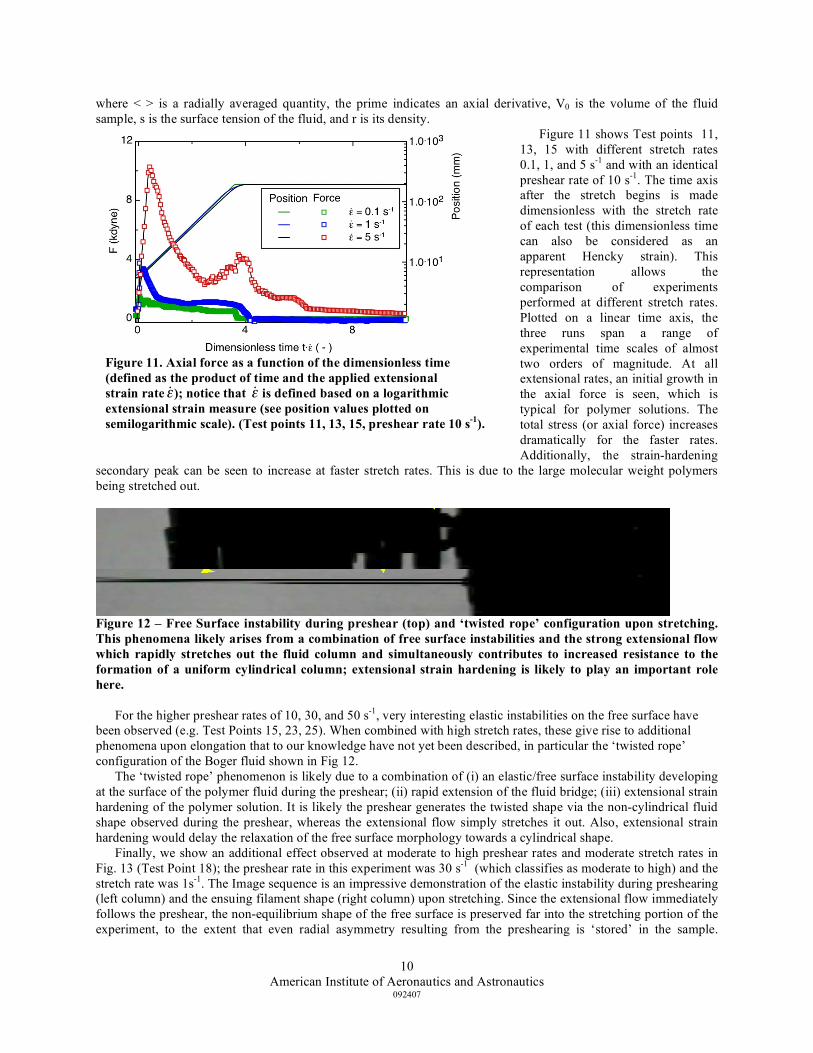
Figure 12 – Free Surface instability during preshear (top) and ‘twisted rope’ configuration upon stretching. This phenomena likely arises from a combination of free surface instabilities and the strong extensional flow which rapidly stretches out the fluid column and simultaneously contributes to increased resistance to the formation of a uniform cylindrical column; extensional strain hardening is likely to play an important role here.
For the higher preshear rates of 10, 30, and 50 s-1, very interesting elastic instabilities on the free surface have
been observed (e.g. Test Points 15, 23, 25). When combined with high stretch rates, these give rise to additional phenomena upon elongation that to our knowledge have not yet been described, in particular the ‘twisted rope’ configuration of the Boger fluid shown in Fig 12.
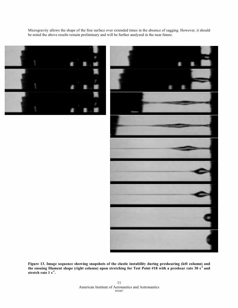
The ‘twisted rope’ phenomenon is likely due to a combination of (i) an elastic/free surface instability developing at the surface of the polymer fluid during the preshear; (ii) rapid extension of the fluid bridge; (iii) extensional strain hardening of the polymer solution. It is likely the preshear generates the twisted shape via the non-cylindrical fluid shape observed during the preshear, whereas the extensional flow simply stretches it out. Also, extensional strain hardening would delay the relaxation of the free surface morphology towards a cylindrical shape. Finally, we show an additional effect observed at moderate to high preshear rates and moderate stretch rates in Fig. 13 (Test Point 18); the preshear rate in this experiment was 30 s-1 (which classifies as moderate to high) and the stretch rate was 1s-1. The Image sequence is an impressive demonstration of the elastic instability during preshearing (left column) and the ensuing filament shape (right column) upon stretching. Since the extensional flow immediately follows the preshear, the non-equilibrium shape of the free surface is preserved far into the stretching portion of the experiment, to the extent that even radial asymmetry resulting from the preshearing is ‘stored’ in the sample.
Figure 11. Axial force as a function of the dimensionless time (defined as the product of time and the applied extensional strain rate
!
˙ " ); notice that
!
˙ " is defined based on a logarithmic extensional strain measure (see position values plotted on semilogarithmic scale). (Test points 11, 13, 15, preshear rate 10 s-1).
American Institute of Aeronautics and Astronautics
092407
11
Microgravity allows the shape of the free surface over extended times in the absence of sagging. However, it should be noted the above results remain preliminary and will be further analyzed in the near future.
Figure 13. Image sequence showing snapshots of the elastic instability during preshearing (left column) and the ensuing filament shape (right column) upon stretching for Test Point #18 with a preshear rate 30 s-1 and stretch rate 1 s-1.
American Institute of Aeronautics and Astronautics
092407
12
VI. Conclusion After ten years of advances and setbacks, the SHERE flight hardware was successfully launched on two different
Shuttle missions. The experiment hardware went up on Shuttle Mission STS-120 (ISS Flight 10A) on October 22, 2007, and 20 fluid samples were launched on Shuttle Mission STS-123 (ISS Flight 1J/A) on March 11, 2008. Starting in late June 2008, the SHERE team witnessed the successful Hardware Install, Checkout Tests, and Dry Run of the hardware. There were some initial difficulties when the Deployment Tool failed to operate properly on-orbit, but this was quickly resolved by using another tool to deploy the fluid module. Shortly thereafter, the SHERE team witnessed the first successful deployment of a non-Newtonian fluid on the ISS. Following that successful test run, all other test run were successfully completed over a two month period. All twenty test runs planned for Increment 17 were completed, and an additional 8 repeat test runs were also completed. Preliminary data evaluating 3 test points with different stretch rates of 0.1, 1, and 5 s-1 with an identical preshear rate of 10 s-1 show an initial growth in the axial force, which is typical for polymer solutions. However, for the higher rotational pre-shear rates of 10, 30, and 50 s-1, very interesting elastic instabilities on the free surface have been observed giving rise to additional phenomena upon elongation that to our knowledge has not yet been described. In particular, the ‘twisted rope’ configuration of the Boger fluid is a new observation. The SHERE PI team is continuing to analyze the data to better understand the effects of rotational pre-shearing on the stress/strain response of a polymeric liquid being stretched in microgravity, and they plan to publish papers on their findings in the near future.
Acknowledgments The authors would like to thank the management, engineering, and operations teams at the NASA Glenn
Research Center for their support. This support extended from the final assembly and testing of the hardware to the performing of flight operations during experiment runs on board the ISS. The hardware development was supported by NASA under Grants NNC04GA41G, NNX07AE08G and NNX08AJ76G.
References 1McKinley, G.H. “Preshear History and Uniaxial Elongation in a Microfilament Extensional Rheometer”—A proposal to
GMX/MIM Program, NASA Lewis Research Center, January 30, 1997. 2McKinley, G.H. and Sridhar, T., “Filament Stretching Rheometry of Complex Fluids,” Annual Review of Fluid Mechanics,
Vol. 34, Annual Reviews Press, Palo Alto, 2002, 375–415. 3Hall, N.R., Logsdon, K.A. and Magee, K.S. “Shear History Extensional Rheology Experiment: A Proposed ISS
Experiment,” 41st AIAA Aerospace Sciences Meeting and Exhibit, AIAA-2006-0524, Reno, Nevada, January 9-12, 2006.