Embed Size (px)
Citation preview
1
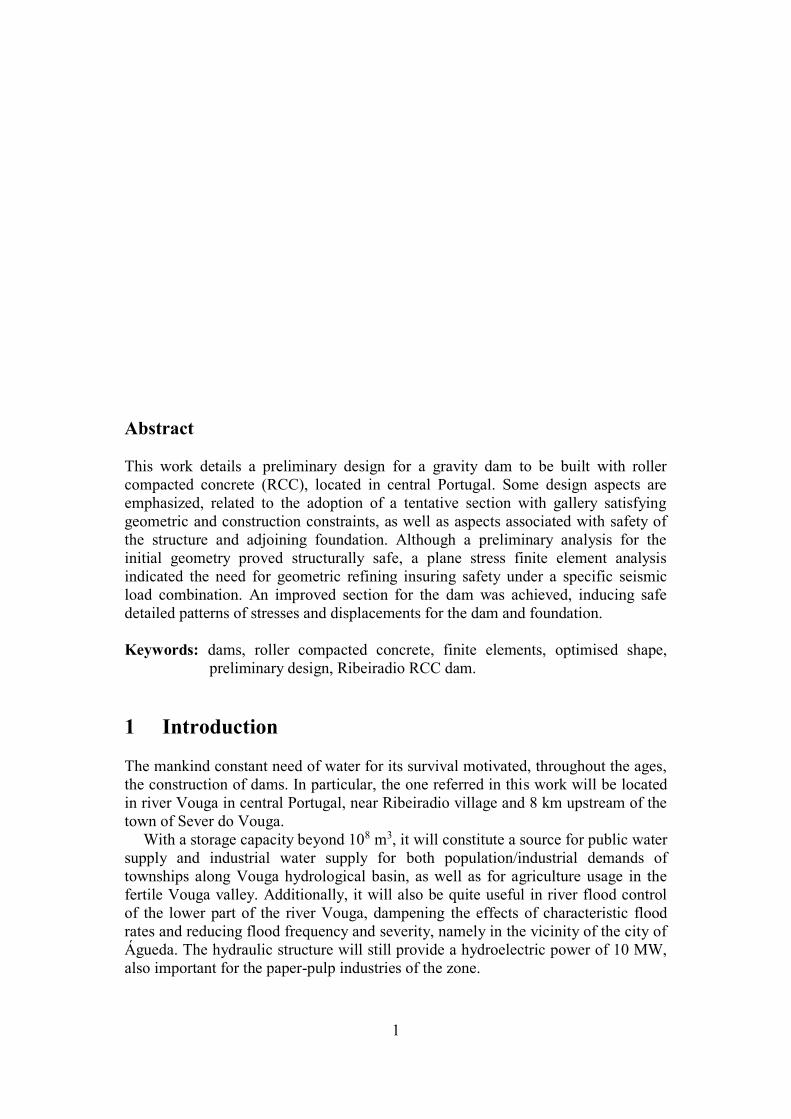
Abstract
This work details a preliminary design for a gravity dam to be built with roller
compacted concrete (RCC), located in central Portugal. Some design aspects are
emphasized, related to the adoption of a tentative section with gallery satisfying
geometric and construction constraints, as well as aspects associated with safety of
the structure and adjoining foundation. Although a preliminary analysis for the
initial geometry proved structurally safe, a plane stress finite element analysis
indicated the need for geometric refining insuring safety under a specific seismic
load combination. An improved section for the dam was achieved, inducing safe
detailed patterns of stresses and displacements for the dam and foundation.
Keywords: dams, roller compacted concrete, finite elements, optimised shape,
preliminary design, Ribeiradio RCC dam.
1 Introduction
The mankind constant need of water for its survival motivated, throughout the ages,
the construction of dams. In particular, the one referred in this work will be located
in river Vouga in central Portugal, near Ribeiradio village and 8 km upstream of the
town of Sever do Vouga.
With a storage capacity beyond 108 m3, it will constitute a source for public water
supply and industrial water supply for both population/industrial demands of
townships along Vouga hydrological basin, as well as for agriculture usage in the
fertile Vouga valley. Additionally, it will also be quite useful in river flood control
of the lower part of the river Vouga, dampening the effects of characteristic flood
rates and reducing flood frequency and severity, namely in the vicinity of the city of
Águeda. The hydraulic structure will still provide a hydroelectric power of 10 MW,
also important for the paper-pulp industries of the zone.
2
As outlined by Hansen and Reinhardt [1] roller-compacted concrete (RCC) has
become one of the most widely used materials for modification and upgrading of
aging embankment dams in the USA, with inherent dam safety and appearance.
Moreover, the RCC techniques made also possible to use RCC gravity dams as an
economically competitive alternative to conventional concrete or embankment dams.
The possibility of rapid construction at low cost constitutes the major advantage of
RCC dams. Because of their horizontal method of construction, stepped spillways
and outlet works are incorporated as an integral part of the RCC structure, with a
reduced velocity at the toe of the spillway. Also because of shorter construction
periods, the river diversion and the potential need of cofferdams are significantly
minimised, especially for large rivers.
Based on these advantages and also on the facts that the crest elevation and
footprint for a RCC dam are considerably and invariably less than for embankment
dams, it is not surprising that the Portuguese authorities planned a RCC dam for
such a convenient site. Moreover the specification of continuous placement of RCC,
minimising cold joints between horizontal layers, would allow contractors bids at
lower unit prices for a dam construction with little risk.
Tendering and the subsequent bidding are increasingly becoming an essential
component of procurement in a wide range of industrial private and public sectors,
including the service industry of engineering consultancy and construction. As
owner of the future hydraulic structure, Portuguese Water Resources and
Environment Ministry (INAG ‘Instituto da Água’) promoted in June 2000 an
international tendering, involving simultaneously conception and construction of the
RCC dam, in order to select the most technically qualified construction consortium.
The 6 distinct construction partnerships that answered to the call until December
2000, organized their candidacies, proposed alternative technical solutions and
submitted their construction bids, based on a provided reference solution of a
preliminary study conducted earlier by COBA in 1999 [2]. This permitted INAG to
classify and rank partnerships through more open, transparent, fair, more
coordinated, efficient and more cost-effective selection practices.
2 Improved Alternative Solution for Ribeiradio Dam
The preliminary design calculations and subsequent finite element analysis, partially
shown in the present paper, resulted from consultancy services permitting the
attendance of a participating partner in the international public tendering promoted
by INAG in 2000, associated with the construction of the above-mentioned RCC
dam. It is typical of similar analysis done at standard civil engineering consultancy
offices throughout Portugal, as a clear indication of continuous technical updating
and upgrading in the art of engineering design.
In order to permit a fair biding of the construction costs of the required complete
dam infrastructure, an alternative more economic solution was searched, whose
structural strength integrity and safety had to be assessed. The alternative solution
proposed was based on minimising the construction costs per unit length, on the
basis of the following sketch of fixed and variable parameters of an idealized
simplified cross section of the gravity dam (Figure 1).
3
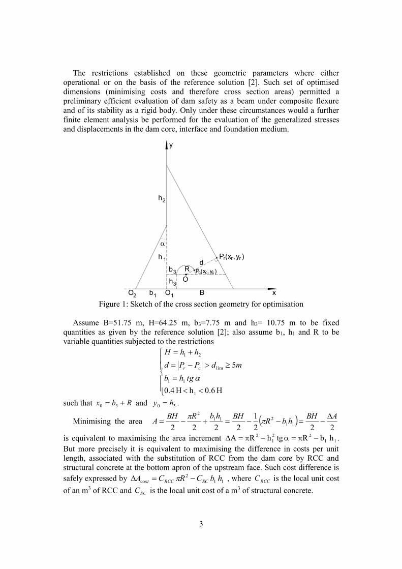
The restrictions established on these geometric parameters where either
operational or on the basis of the reference solution [2]. Such set of optimised
dimensions (minimising costs and therefore cross section areas) permitted a
preliminary efficient evaluation of dam safety as a beam under composite flexure
and of its stability as a rigid body. Only under these circumstances would a further
finite element analysis be performed for the evaluation of the generalized stresses
and displacements in the dam core, interface and foundation medium.
y
3b
O
Rd
h3
h 1
Pr(xr,yr )
)yc,c x( cP
O1 B x1b2O
2h
Figure 1: Sketch of the cross section geometry for optimisation
Assume B=51.75 m, H=64.25 m, b3=7.75 m and h3= 10.75 m to be fixed
quantities as given by the reference solution [2]; also assume b1, h1 and R to be
variable quantities subjected to the restrictions
H 0.6 h H 0.4
5
1
11
lim
21
tghb
mdPPd
hhH
cr
such that Rbx 30 and 30 hy .
Minimising the area 222
1
222211
211
2 ABHhbR
BHhbRBHA
is equivalent to maximising the area increment l1
22
1
2 hbRtghRA .
But more precisely it is equivalent to maximising the difference in costs per unit
length, associated with the substitution of RCC from the dam core by RCC and
structural concrete at the bottom apron of the upstream face. Such cost difference is
safely expressed by 11
2
cos hbCRCA SCRCCt , where RCCC is the local unit cost
of an m3 of RCC and SCC is the local unit cost of a m3 of structural concrete.
4
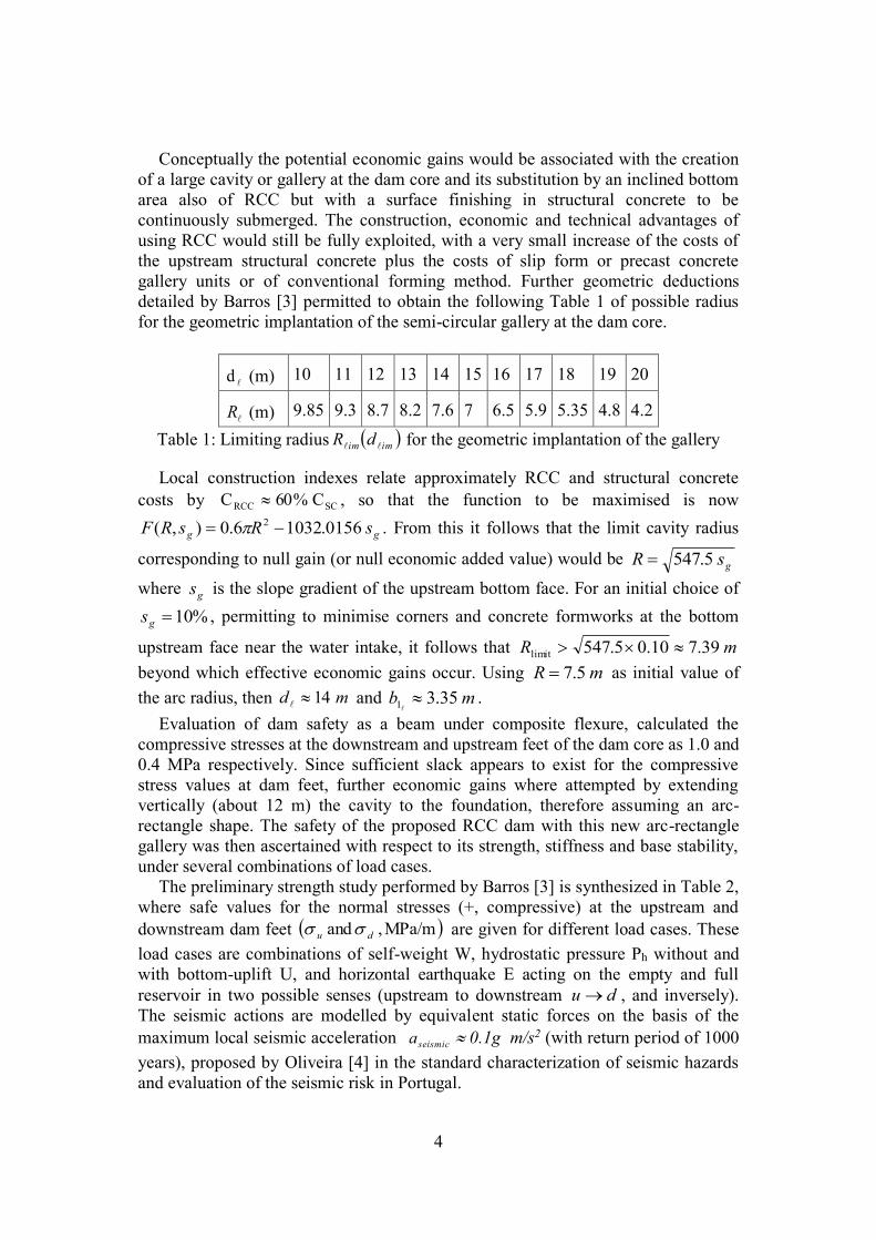
Conceptually the potential economic gains would be associated with the creation
of a large cavity or gallery at the dam core and its substitution by an inclined bottom
area also of RCC but with a surface finishing in structural concrete to be
continuously submerged. The construction, economic and technical advantages of
using RCC would still be fully exploited, with a very small increase of the costs of
the upstream structural concrete plus the costs of slip form or precast concrete
gallery units or of conventional forming method. Further geometric deductions
detailed by Barros [3] permitted to obtain the following Table 1 of possible radius
for the geometric implantation of the semi-circular gallery at the dam core.
d (m) 10 11 12 13 14 15 16 17 18 19 20
R (m) 9.85 9.3 8.7 8.2 7.6 7 6.5 5.9 5.35 4.8 4.2
Table 1: Limiting radius imim dR for the geometric implantation of the gallery
Local construction indexes relate approximately RCC and structural concrete
costs by SCRCC C%60C , so that the function to be maximised is now
gg sRsRF 0156.10326.0),( 2 . From this it follows that the limit cavity radius
corresponding to null gain (or null economic added value) would be gsR 5.547
where gs is the slope gradient of the upstream bottom face. For an initial choice of
%10gs , permitting to minimise corners and concrete formworks at the bottom
upstream face near the water intake, it follows that mR 39.710.05.547limit
beyond which effective economic gains occur. Using mR 5.7 as initial value of
the arc radius, then md 14 and mb 35.31
.
Evaluation of dam safety as a beam under composite flexure, calculated the
compressive stresses at the downstream and upstream feet of the dam core as 1.0 and
0.4 MPa respectively. Since sufficient slack appears to exist for the compressive
stress values at dam feet, further economic gains where attempted by extending
vertically (about 12 m) the cavity to the foundation, therefore assuming an arc-
rectangle shape. The safety of the proposed RCC dam with this new arc-rectangle
gallery was then ascertained with respect to its strength, stiffness and base stability,
under several combinations of load cases.
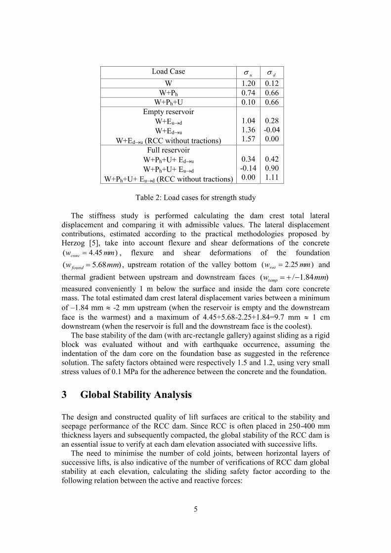
The preliminary strength study performed by Barros [3] is synthesized in Table 2,
where safe values for the normal stresses (+, compressive) at the upstream and
downstream dam feet MPa/m,and du are given for different load cases. These
load cases are combinations of self-weight W, hydrostatic pressure Ph without and
with bottom-uplift U, and horizontal earthquake E acting on the empty and full
reservoir in two possible senses (upstream to downstream du , and inversely).
The seismic actions are modelled by equivalent static forces on the basis of the
maximum local seismic acceleration seismica 0.1g m/s2 (with return period of 1000
years), proposed by Oliveira [4] in the standard characterization of seismic hazards
and evaluation of the seismic risk in Portugal.
5
Load Case u d
W 1.20 0.12
W+Ph 0.74 0.66
W+Ph+U 0.10 0.66
Empty reservoir
W+Eud
W+Edu
W+Edu (RCC without tractions)
1.04
1.36
1.57
0.28
-0.04
0.00
Full reservoir
W+Ph+U+ Edu
W+Ph+U+ Eud
W+Ph+U+ Eud (RCC without tractions)
0.34
-0.14
0.00
0.42
0.90
1.11
Table 2: Load cases for strength study
The stiffness study is performed calculating the dam crest total lateral
displacement and comparing it with admissible values. The lateral displacement
contributions, estimated according to the practical methodologies proposed by
Herzog [5], take into account flexure and shear deformations of the concrete
)45.4( mmwconc , flexure and shear deformations of the foundation
)68.5( mmw found , upstream rotation of the valley bottom )25.2( mmwrot and
thermal gradient between upstream and downstream faces )84.1/( mmwtemp
measured conveniently 1 m below the surface and inside the dam core concrete
mass. The total estimated dam crest lateral displacement varies between a minimum
of –1.84 mm -2 mm upstream (when the reservoir is empty and the downstream
face is the warmest) and a maximum of 4.45+5.68-2.25+1.84=9.7 mm 1 cm
downstream (when the reservoir is full and the downstream face is the coolest).
The base stability of the dam (with arc-rectangle gallery) against sliding as a rigid
block was evaluated without and with earthquake occurrence, assuming the
indentation of the dam core on the foundation base as suggested in the reference
solution. The safety factors obtained were respectively 1.5 and 1.2, using very small
stress values of 0.1 MPa for the adherence between the concrete and the foundation.
3 Global Stability Analysis
The design and constructed quality of lift surfaces are critical to the stability and
seepage performance of the RCC dam. Since RCC is often placed in 250-400 mm
thickness layers and subsequently compacted, the global stability of the RCC dam is
an essential issue to verify at each dam elevation associated with successive lifts.
The need to minimise the number of cold joints, between horizontal layers of
successive lifts, is also indicative of the number of verifications of RCC dam global
stability at each elevation, calculating the sliding safety factor according to the
following relation between the active and reactive forces:

6
forcesActive
forcesReactiveSLIDINGF
(1)
The active forces result from the water pressure acting on the upstream face of
the dam, while the reactive forces are guaranteed by the horizontal frictional forces
RDFH mobilized in the surface between concrete layers of RCC or between concrete
and the foundation soil. The latter are expressed by:
ActgFH ddnRD ' (2)
where n are the local normal stresses at each element area A , dc is the design
cohesion and '
d is the design friction angle. The design values of the geotechnical
parameters (cohesion and friction angle) were obtained from the prescriptions of
Eurocode 7 [6], dividing the characteristic values kc and '
k by the corresponding
partial safety factors, respectively c and , as expressed in equations (3) and (4).
'' kd
tgarctg
c
k
d
cc
(3)
(4)
The partial safety factors and c are shown in the following Table 3, for the two
types of analyses to be performed.
Analysis ’ c
Static 1.5 4.0
Dynamic 1.1 3.0
Table 3: Geotechnical partial safety factors
The characteristic values of the geotechnical parameters for global stability
analysis are given in Table 4, for the two types of interface zones between
contacting materials.
Surface '
k (degrees) kc (kPa)
Concrete-concrete (RCC) 42.0 550.0
Concrete-foundation 45.0 400.0
Table 4: Characteristic values of geotechnical parameters
The potential sliding stability at the elevations of the cold joints proposed in the
reference solution [2] was ascertained, and the corresponding sliding safety factors
are synthesized in the following Table 5 extracted from [7].
7
Height of Sliding Surface (m) Sliding Safety Factor
40 1.35
50 1.49
60 1.60
70 1.81
80 2.08
Table 5: Sliding safety factors for different heights
4 Finite Element Analysis
Since the previous preliminary analyses have been successfully performed for the
original and improved optimised cross section, ascertaining the overall or global safe
performance and behaviour of the RCC dam, a detailed local analysis by the finite
element method seems now quite justifiable. Such analysis will characterize the
pattern of generalized stresses and displacements of the complete model, namely in
the RCC core, at the interface between dam and foundation, and in all the modelled
portion of the foundation soil.
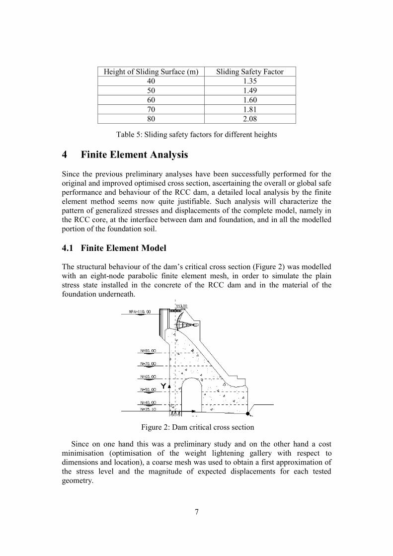
4.1 Finite Element Model
The structural behaviour of the dam’s critical cross section (Figure 2) was modelled
with an eight-node parabolic finite element mesh, in order to simulate the plain
stress state installed in the concrete of the RCC dam and in the material of the
foundation underneath.
Figure 2: Dam critical cross section
Since on one hand this was a preliminary study and on the other hand a cost
minimisation (optimisation of the weight lightening gallery with respect to
dimensions and location), a coarse mesh was used to obtain a first approximation of
the stress level and the magnitude of expected displacements for each tested
geometry.

8
The two meshes tested during finite element modelling are visualised in Figure 3,
obtained through the use of VIFEM software (Visual Interface for Finite Element
Method) developed by Teixeira [8]. The original geometry refers to the arc-rectangle
gallery proposed for preliminary analysis; the improved geometry corresponds to a
decrease of its dimensions with a more downstream implantation in the dam core.
Original geometry Improved geometry
Figure 3: Finite element meshes
The structural behaviour of the dam could only be modelled with acceptable
accuracy taking in account the existing interaction between the RCC core and the
foundation material on which the dam rests. According to Figure 4 a certain amount
of surrounding soil was also meshed, with the purpose of minimising the boundary
effects due to the finite character of the mesh.
Figure 4: Finite element mesh of dam and foundation, for the improved geometry

9
The boundary conditions considered correspond to a rigid link to the bottom layer
of the foundation material and horizontal restriction to movement on both vertical
boundaries of the meshed domain.
The mechanical properties of the materials involved in the simulation of both the
foundation and the RCC core of the dam are shown in the following Table 6, where
E is the elastic modulus, the Poisson ratio and the specific volumetric weight.
Material E (GPa) (kN/m3 )
1 - Foundation 2 0.35 19
2 - RCC 20 0.22 24
Table 6: Material data for the design of the RCC dam
4.2 External Loads
The external loads applied to the RCC dam for this finite element analysis are the
sum of two kinds of forces. The first kind corresponds to mass forces mxf and myf
due to seismic and gravity accelerations, respectively in the x and y directions,
calculated per unit volume by:
3/45.2 mkNg
af concrete
seismic
mx (5)
3/24 mkNf concretemy (6)
The term seismica is the maximum horizontal ground acceleration (here acting in
the body of the dam), which was already justified to assume the value of 1.0 m/s2.
The second kind of forces represents the external pressures induced by the water
on the upstream face of the dam (Figure 5), including the hydrodynamic term
accounting for the seismic effect in the water mass, calculated with Westergard’s
parabola [9]. The hydrostatic and hydrodynamic pressures are given respectively by
yHyp waterchydrostati )( (7)
2
2
1)(H
yKypseismic (8)
Figure 5: Hydrostatic and hydrodynamic pressures on the upstream face
10
where mH 75 is the maximum height of water in the reservoir, water is the water
volumetric specific weight and the scaling factor Hg
aK water
seismic .
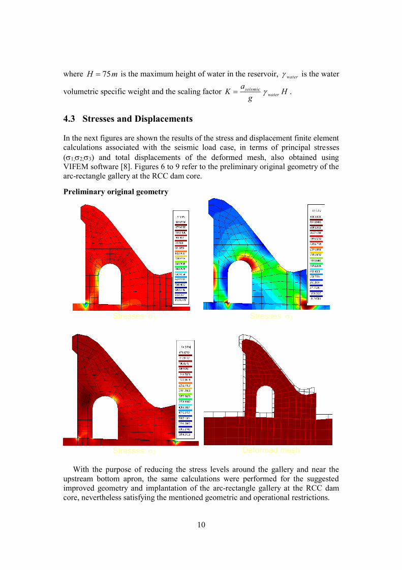
4.3 Stresses and Displacements
In the next figures are shown the results of the stress and displacement finite element
calculations associated with the seismic load case, in terms of principal stresses
(1,2,3) and total displacements of the deformed mesh, also obtained using VIFEM software [8]. Figures 6 to 9 refer to the preliminary original geometry of the
arc-rectangle gallery at the RCC dam core.
Preliminary original geometry
Stresses 1
Stresses 3
Stresses 2 Deformed mesh
With the purpose of reducing the stress levels around the gallery and near the
upstream bottom apron, the same calculations were performed for the suggested
improved geometry and implantation of the arc-rectangle gallery at the RCC dam
core, nevertheless satisfying the mentioned geometric and operational restrictions.
11
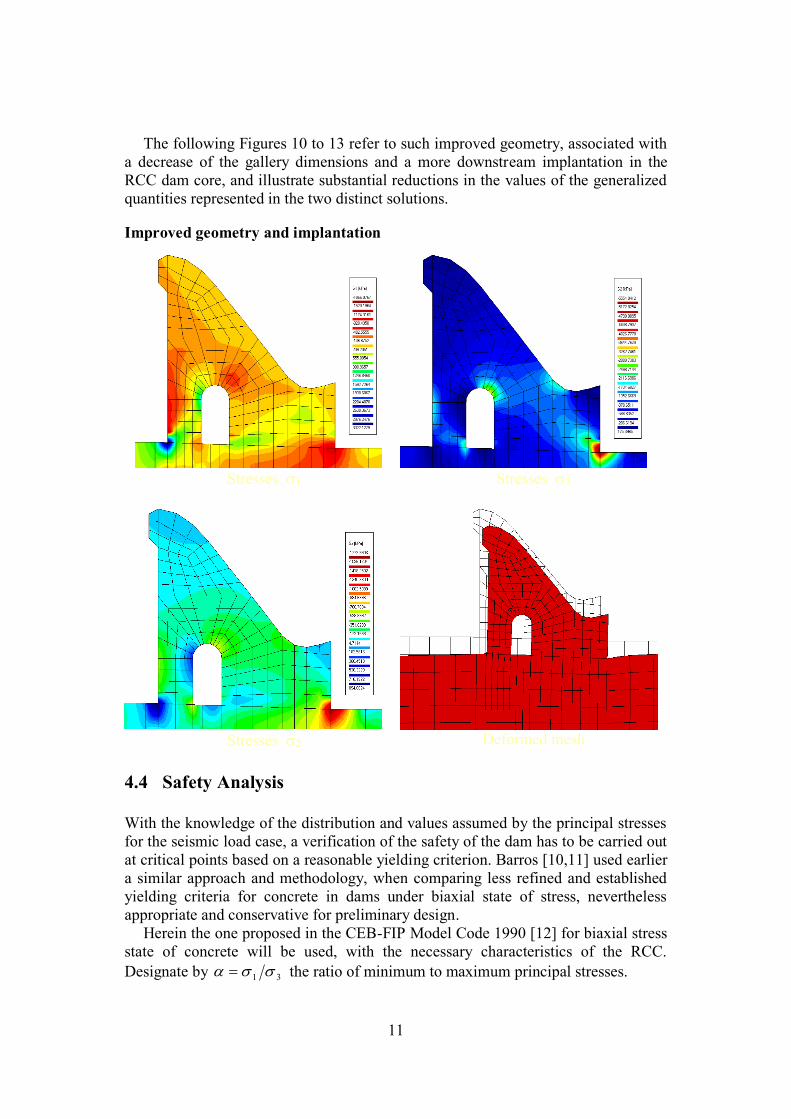
The following Figures 10 to 13 refer to such improved geometry, associated with
a decrease of the gallery dimensions and a more downstream implantation in the
RCC dam core, and illustrate substantial reductions in the values of the generalized
quantities represented in the two distinct solutions.
Improved geometry and implantation
Stresses 1
Stresses 3
Stresses 2 Deformed mesh
4.4 Safety Analysis
With the knowledge of the distribution and values assumed by the principal stresses
for the seismic load case, a verification of the safety of the dam has to be carried out
at critical points based on a reasonable yielding criterion. Barros [10,11] used earlier
a similar approach and methodology, when comparing less refined and established
yielding criteria for concrete in dams under biaxial state of stress, nevertheless
appropriate and conservative for preliminary design.
Herein the one proposed in the CEB-FIP Model Code 1990 [12] for biaxial stress
state of concrete will be used, with the necessary characteristics of the RCC.
Designate by 31 the ratio of minimum to maximum principal stresses.
12
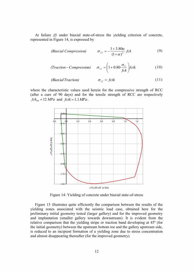
At failure (f) under biaxial state-of-stress the yielding criterion of concrete,
represented in Figure 14, is expressed by
fck)ompression(Biaxial C f 23)1(
80.31
(9)
fctkfck
n)Compressio(Traction f
3
1 80.01
(10)
fctkTraction)(Biaxial f 1 (11)
where the characteristic values used herein for the compressive strength of RCC
(after a cure of 90 days) and for the tensile strength of RCC are respectively
MPafck 1290 and MPafctk 1.1 .
-1.30
-1.10
-0.90
-0.70
-0.50
-0.30
-0.10
0.10
-0.2 0.0 0.2 0.4 0.6 0.8 1.0 1.2
1f,2f,3f (x fck)
1
f,
2f,
3f (x
fck)
Eq. 3.2a
Eq. 3.2b
Eq. 3.3a
Eq. 3.3b
Eq. 3.4
Figure 14: Yielding of concrete under biaxial state-of-stress
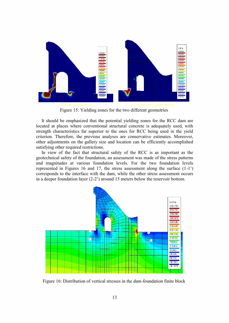
Figure 15 illustrates quite efficiently the comparison between the results of the
yielding zones associated with the seismic load case, obtained here for the
preliminary initial geometry tested (larger gallery) and for the improved geometry
and implantation (smaller gallery towards downstream). It is evident from the
relative comparison that the yielding stripe or traction band developing at 45º (for
the initial geometry) between the upstream bottom toe and the gallery upstream side,
is reduced to an incipient formation of a yielding zone due to stress concentration
and almost disappearing thereafter (for the improved geometry).
13
Initial geometry Improved geometry Figure 15: Yielding zones for the two different geometries
It should be emphasized that the potential yielding zones for the RCC dam are
located at places where conventional structural concrete is adequately used, with
strength characteristics far superior to the ones for RCC being used in the yield
criterion. Therefore, the previous analyses are conservative estimates. Moreover,
other adjustments on the gallery size and location can be efficiently accomplished
satisfying other required restrictions.
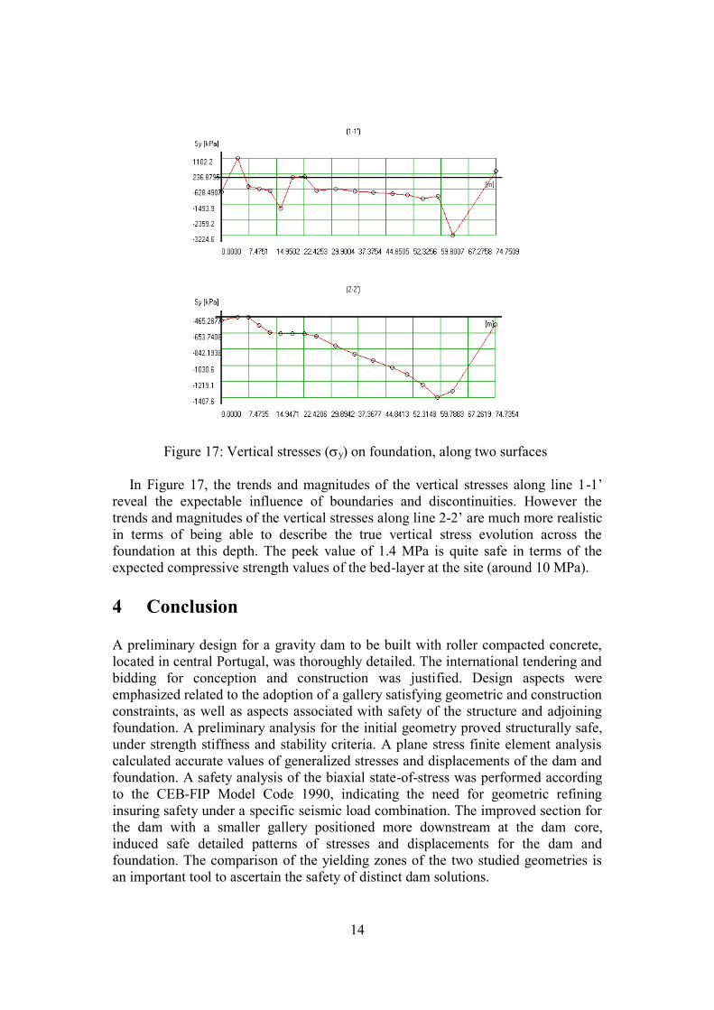
In view of the fact that structural safety of the RCC is as important as the
geotechnical safety of the foundation, an assessment was made of the stress patterns
and magnitudes at various foundation levels. For the two foundation levels
represented in Figures 16 and 17, the stress assessment along the surface (1-1’)
corresponds to the interface with the dam, while the other stress assessment occurs
in a deeper foundation layer (2-2’) around 15 meters below the reservoir bottom.
Figure 16: Distribution of vertical stresses in the dam-foundation finite block
14
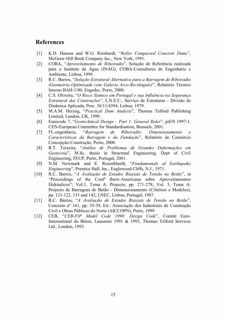
Figure 17: Vertical stresses (y) on foundation, along two surfaces
In Figure 17, the trends and magnitudes of the vertical stresses along line 1-1’
reveal the expectable influence of boundaries and discontinuities. However the
trends and magnitudes of the vertical stresses along line 2-2’ are much more realistic
in terms of being able to describe the true vertical stress evolution across the
foundation at this depth. The peek value of 1.4 MPa is quite safe in terms of the
expected compressive strength values of the bed-layer at the site (around 10 MPa).
4 Conclusion A preliminary design for a gravity dam to be built with roller compacted concrete,
located in central Portugal, was thoroughly detailed. The international tendering and
bidding for conception and construction was justified. Design aspects were
emphasized related to the adoption of a gallery satisfying geometric and construction
constraints, as well as aspects associated with safety of the structure and adjoining
foundation. A preliminary analysis for the initial geometry proved structurally safe,
under strength stiffness and stability criteria. A plane stress finite element analysis
calculated accurate values of generalized stresses and displacements of the dam and
foundation. A safety analysis of the biaxial state-of-stress was performed according
to the CEB-FIP Model Code 1990, indicating the need for geometric refining
insuring safety under a specific seismic load combination. The improved section for
the dam with a smaller gallery positioned more downstream at the dam core,
induced safe detailed patterns of stresses and displacements for the dam and
foundation. The comparison of the yielding zones of the two studied geometries is
an important tool to ascertain the safety of distinct dam solutions.
15
References
[1] K.D. Hansen and W.G. Reinhardt, “Roller Compacted Concrete Dams”,
McGraw-Hill Book Company Inc., New York, 1991.
[2] COBA, “Aproveitamento de Ribeiradio”, Solução de Referência realizada
para o Instituto da Água (INAG), COBA-Consultores de Engenharia e
Ambiente, Lisboa, 1999.
[3] R.C. Barros, “Solução Estrutural Alternativa para a Barragem de Ribeiradio
(Geometria Optimizada com Galeria Arco-Rectângulo)”, Relatório Técnico
Interno BAH-1/00, Engedec, Porto, 2000.
[4] C.S. Oliveira, “O Risco Sísmico em Portugal e sua Influência na Segurança
Estrutural das Construções”, L.N.E.C., Serviço de Estruturas - Divisão de
Dinâmica Aplicada, Proc. 36/11/4394, Lisboa, 1979.
[5] M.A.M. Herzog, “Practical Dam Analysis”, Thomas Telford Publishing
Limited, London, UK, 1999.
[6] Eurocode 7, “Geotechnical Design – Part 1: General Rules”, prEN 1997-1,
CEN-European Committee for Standardisation, Brussels, 2001.
[7] FL-engenharia, “Barragem de Ribeiradio: Dimensionamento e
Características da Barragem e da Fundação”, Relatório de Consórcio
Concepção-Construção, Porto, 2000.
[8] R.T. Teixeira, “Análise de Problemas de Grandes Deformações em
Geotecnia”, M.Sc. thesis in Structural Engineering, Dept of Civil
Engineering, FEUP, Porto, Portugal, 2001.
[9] N.M. Newmark and E. Rosenblueth, “Fundamentals of Earthquake
Engineering”, Prentice Hall, Inc., Englewood Cliffs, N.J., 1971.
[10] R.C. Barros, “A Avaliação de Estados Biaxiais de Tensão no Betão”, in
“Proceedings of the Confª Ibero-Americana sobre Aproveitamentos
Hidráulicos”; Vol.1, Tema A: Projecto, pp. 271-278; Vol. 3, Tema A:
Projecto de Barragens de Betão - Dimensionamento (Critérios e Modelos),
pp. 121-122, 133 and 142; LNEC, Lisboa, Portugal, 1987.
[11] R.C. Barros, “A Avaliação de Estados Biaxiais de Tensão no Betão”,
Concreto nº 161, pp. 35-39, Ed.: Associação dos Industriais de Construção
Civil e Obras Públicas do Norte (AICCOPN), Porto, 1999.
[12] CEB, “CEB-FIP Model Code 1990: Design Code”, Comité Euro-
International du Béton, Lausanne 1991 & 1993, Thomas Telford Services
Ltd., London, 1993.