Embed Size (px)
Citation preview

Preface
Thank you for choosing GTAKE GK600 Series General Purpose AC Motor Drives. This user
manual presents a detailed description of GK600 series with respect to product features,
structural characteristics, functions, installation, parameter setting, troubleshooting,
commissioning and daily maintenance, etc. Be sure to carefully read through the safety
precautions before use, and use this product on the premise that personnel and equipment
safety is ensured.
IMPORTANT NOTES
Please assure the intactness of product enclosure and all safety covers beforeinstallation .Operation must conform to the requirements of this manual and local industrialsafety regulations and/or electrical codes.
Contents of this manual may be subject to appropriate modification as a result of productupgrade, specification change and update of the manual.
In the event of damage or loss of user manual, users may ask local distributors, offices orour Technical Service Department for a new one.
If any item as stated in this manual is not clear, please contact our Technical ServiceDepartment.
If any anomaly occurs after power up or during the operation, it is essential to stop themachine and identify the fault or seek technical services as soon as possible.
Telephone number of our Technical Service Department: (+86) 0755-86392601.

Besides there are some changes on the manner of writing, error correction, and designation replacement like control panel instead of keypad, following is the material new or updated information in this user manual.
Summary of Changes
The information below summaries changes made in April 2016 for GK600 Series General Purpose AC Motor Drives User Manual, version A01-EN.
Chapter 2
1 Nameplate information altered.
2
Product models GK600-2T0.4 ~ GK600-2T110,
GK600-4T0.75G/1.5LB ~ GK600-4T1.5G/2.2LB, and GK600-4T500G
~ GK600-4T630G, as well as their part drawings, appearance,
dimensions and weight added.
3 Frame type (not size) of GK600-4T90 changed.
Chapter 3 1 Related information of all new-added models added, including those
requiring input voltage 220VAC.
Chapter 5
1 Parameter group H1: Profibus-DP communication parameters added.
2
Following parameter names, parameter values and/or their defaults
changed: A0-07, A0-01~A0-09, b1-05, b1-08, b1-10, b1-11, b1-12,
b2-13, b2-14, C0-01~C0-10, C0-17, C1-00~C1-03, C2-00,
C3-00-C3-02, C3-11, d0-00, d0-04, d0-05, d0-22, d1-16, d1-17, d3-05,
d4-16, d4-17, E1-01, E1-07, E1-13, F0-08, F0-09~F0-13, H0-00,
H0-02, L0-03, L1-00, U0-05, U0-18, U0-34, U1-00, U1-01~U1-26.
3 Parameters added: c0-21, c2-29, H1-00 ~ H1-21.
Chapter 6 1 Specification of above-mentioned parameters in Chapter 5 updated or
added.
Chapter 7 1 Fault code PFS and its specification added.
Appendix 1
Information of Table 1, Table 3, Table 6, Table 10, Table 13, table 14,
table 15, table 19, table 21, table 25, table 27, table 28, table 29, table
30, table 31, table 32, table 33, table 34, table 35, table 36, table 37,
table 38, table 39, table 40, table 41, table 42, and table 43 updated.

Table of Contents
Preface .............................................................................................................................. - 1 -
Chapter 1 Safety Precautions .......................................................................................... - 1 -
1.1 Safety Considerations ...................................................................................... - 1 -
1.2 Other Considerations ....................................................................................... - 5 -
Chapter 2 Product Information ........................................................................................ - 7 -
2.1 Model Explanation............................................................................................ - 7 -
2.2 Nameplate Information ..................................................................................... - 7 -
2.3 Information of Product Model ........................................................................... - 8 -
2.4 Technical Features of GK600 .......................................................................... - 11 -
2.5 Parts Drawing ................................................................................................ - 14 -
2.6 Appearance, Mounting Dimensions and Weight ............................................. - 16 -
2.7 External Dimensions of Control Panel ............................................................ - 21 -
2.8 External Dimensions of Control Panel Bracket ............................................... - 22 -
Chapter 3 Installation and Wiring .................................................................................. - 23 -
3.1 Installation Environment ................................................................................. - 23 -
3.2 Minimum Mounting Clearances ...................................................................... - 23 -
3.3 Remove & Mount Control Panel and Cover .................................................... - 25 -
3.4 Configuration of Peripheral Devices ............................................................... - 29 -
3.5 Terminal Configuration ................................................................................... - 34 -

3.6 Main Circuit Terminals and Wiring .................................................................. - 34 -
3.7 Control Terminal Wiring .................................................................................. - 40 -
3.8 Control Terminal Specification ........................................................................ - 44 -
3.9 Control Terminal Usage .................................................................................. - 45 -
3.10 Instruction of Signal Switches ......................................................................... - 51 -
3.11 EMI Solutions ................................................................................................. - 51 -
Chapter 4 Operation and Run Instructions ................................................................... - 54 -
4.1 Operation of Control Panel ............................................................................. - 54 -
4.2 First-time Power up ........................................................................................ - 70 -
Chapter 5 List of Parameters ......................................................................................... - 71 -
Chapter 6 Specification of Parameters ........................................................................ - 115 -
Group A System Parameters and Parameter Management ....................................... - 115 -
Group A0 System Parameters ............................................................................. - 115 -
Group A1 User-defined Display Parameters ......................................................... - 118 -
Group b Run Parameter Setting ...............................................................................- 120 -
Group b0 Frequency Setting ................................................................................- 120 -
Group b1 Start/Stop Control .................................................................................- 133 -
Group b2 Accel/Decel Parameters .......................................................................- 139 -
Group C Input and Output Terminals ........................................................................- 145 -
Group C0 Digital Input .........................................................................................- 145 -
Group C1 Digital Output .......................................................................................- 158 -
Group C2 Analog and Pulse Input ........................................................................- 165 -
Group C3 Analog and Pulse Output .....................................................................- 170 -
Group C4 Automatic Correction of Analog Input...................................................- 175 -
Group d Motor and Control Parameters ....................................................................- 176 -
Group d0 Parameters of Motor 1 ..........................................................................- 176 -

Group d1 V/f Control Parameters of Motor 1 ........................................................- 180 -
Group d2 Vector Control Parameters of Motor 1 ..................................................- 187 -
Group d3 Parameters of Motor 2 ..........................................................................- 191 -
Group d4 V/f Control Parameters of Motor 2 ........................................................- 192 -
Group d5 Vector Control Parameters of Motor 2 ..................................................- 193 -
Group E Enhanced Function and Protection Parameters ..........................................- 194 -
Group E0 Enhanced Function ..............................................................................- 194 -
Group E1 Protection Parameters .........................................................................- 198 -
Group F Application ..................................................................................................- 202 -
Group F0 Process PID .........................................................................................- 202 -
Group F1 Multi-step Frequency............................................................................- 208 -
Group F2 Simple PLC .......................................................................................... - 211 -
Group F3 Wobble Frequency and Fixed Length Count ........................................- 220 -
Group H Communication Parameters .......................................................................- 224 -
Group H0 MODBUS Communication Parameters ................................................- 224 -
Group H1 Profibus-DP communication parameters ..............................................- 226 -
Group L Keys and Display of Control Panel ..............................................................- 226 -
Group L0 Keys of Control Panel ...........................................................................- 226 -
Group L1 Control Panel Display Setting ...............................................................- 228 -
Group U Monitoring ..................................................................................................- 230 -
Group U0 Status Monitoring .................................................................................- 230 -
Group U1 History Fault ........................................................................................- 234 -
Chapter 7 Troubleshooting ...........................................................................................- 236 -
7.1 Fault Causes and Troubleshooting ................................................................- 236 -
Chapter 8 Maintenance .................................................................................................- 244 -
8.1 Routine Inspection ........................................................................................- 244 -
8.2 Regular Maintenance ....................................................................................- 245 -

8.3 Replacement of Vulnerable Parts ..................................................................- 246 -
8.4 Storage .........................................................................................................- 247 -
Appendix Communication Protocol .............................................................................- 249 -
1. Networking Mode ...............................................................................................- 249 -
2. Interface Mode ...................................................................................................- 249 -
3. Communication Mode ........................................................................................- 249 -
4. Protocol Format .................................................................................................- 250 -
5. Protocol Function ...............................................................................................- 252 -
6. Operation Instructions ........................................................................................- 264 -
7. LRC/CRC Generation ........................................................................................- 268 -

GK600 User Manual Chapter 1 Safety Precautions
- 1 -
Chapter 1 Safety Precautions
Safety Precautions
Safety signs in this manual:
WARNING: indicates the situation in which the failure to follow operating requirements may result in fire or serious personal injury or even death.
ATTENTION: indicates the situation in which the failure to follow operating requirements may cause moderate or slight injury and damage to equipment.
Users are requested to read this chapter carefully when installing, commissioning and repairing this product and perform the operation according to safety precautions as set forth in this chapter without violation. GTAKE bears no responsibility for any injury and loss as a result of any violation operation.
1.1 Safety Considerations
1.1.1 Prior to Installation
WARNING
Do not touch control terminals, circuit boards and any other electronic parts and components with bare hands.
Do not use the drive whose component(s) is/are missing or damaged. Failure to comply may result in more faults and/or personal injury even death.
ATTENTION
Check if the product information indicated on the nameplate is consistent with the order requirements. If not, do not install it.
Do not install the drive in the event that the packing list does not match the real equipment.
1.1.2 Installation
WARNING
Only qualified personnel familiar with adjustable frequency AC drives and associated machinery should plan or implement the installation. Failure to comply may result in equipment damage and/or personnel injury even death.

Chapter 1 Safety Precautions GK600 User Manual
- 2 -
This equipment must be mounted on metal or other flame retardant objects. Failure to comply may result in fire.
This equipment must be mounted in an area which is away from combustibles and heat sources. Failure to comply may result in fire.
This equipment must in no case be mounted in the environment exposed to explosive gases. Failure to comply may result in explosion.
Never adjust mounting bolts of this equipment, especially the ones with red marks. Failure to comply may result in equipment damage.
ATTENTION
Handle the equipment gently and take hold of its sole plate so as to avoid foot injury or equipment damage.
Mount the equipment where its weight can be withstood. Failure to comply may result in equipment damage and/or personnel injury if falling happens.
Make sure the installation environment conforms to the requirements as stated in Section 2.4. If not, de-rating is necessary. Failure to comply may result in equipment damage.
Prevent drilling residues, wire ends and screws from falling into the equipment during installation. Failure to comply may result in faults or equipment damage.
When mounted in a cabinet, this equipment should be provided with appropriate heat dissipation. Failure to comply may result in faults or equipment damage.
1.1.3 Wiring
WARNING
Only qualified personnel familiar with adjustable frequency AC drives and associated machinery should plan or implement the wiring. Failure to comply may result in personnel injury and/or equipment damage.
Wiring must strictly conform to this manual. Failure to comply may result in personnel injury and/or equipment damage.
Make sure the input power supply has been completely disconnected before wiring. Failure to comply may result in personnel injury and/or equipment damage.
All wiring operations must comply with EMC and safety regulations and/or electrical codes, and the conductor diameter should conform to recommendations of this manual. Failure to comply may result in personnel injury and/or equipment damage.
Since overall leakage current of this equipment may be bigger than 3.5mA, for safety's sake, this equipment and its associated motor must be well grounded so as to avoid risk of electric shock.
Be sure to implement wiring in strict accordance with the marks on this equipment’s

GK600 User Manual Chapter 1 Safety Precautions
- 3 -
terminals. Never connect three-phase power supply to output terminals U/T1, V/T2 and W/T3. Failure to comply may result in equipment damage.
Install braking resistors at terminals and B2 only. Failure to comply may result in equipment damage.
Install DC reactor at terminals and , and remove the jumper connected at and . Never connect this jumper and DC reactor to any other terminals. Failure to comply may result in short circuit and equipment damage.
Wiring screws and bolts for main circuit terminals must be screwed tightly. Failure to comply may result in equipment damage.
AC 220V signal is prohibited from connecting to other terminals than control terminals RA, RB and RC. Failure to comply may result in equipment damage.
ATTENTION
Since all adjustable frequency AC drives from GTAKE have been subjected to hi-pot test before delivery, users are prohibited from implementing such a test on this equipment. Failure to comply may result in equipment damage.
Signal wires should be away from main power lines to the best of the possibility. If this cannot be ensured, vertical cross-arrangement shall be implemented, otherwise interference noise to control signal may occur.
If motor cables are longer than 100m, it is recommended output AC reactor be used. Failure to comply may result in faults.
The coder must be provided with shielded cables whose shielded layer must be well grounded.
1.1.4 Run
WARNING
Drives which have been stored for more than 2 years should be used with voltage regulator to gradually boost the voltage when applying power to the drives. Failure to comply may result in equipment damage.
Be sure to implement the wiring as per Section 3.4 before applying power to the drive. Failure to comply may result in equipment damage and/or electric shock hazard.
Be sure to confirm the completion and correctness of the drive wiring and close the cover before applying power to the drive. Do not open the cover after applying power. Failure to comply may result in electric shock hazard.
After applying the power, never touch the drive and peripheral circuits no matter what state the drive is under, otherwise there will be electric shock hazard.
Prior to running the drive, make sure there is no person in surrounding area who can reach the motor so as to prevent personal injury.
+ 2/B1
+ 1 + 2 + 1+ 2

Chapter 1 Safety Precautions GK600 User Manual
- 4 -
When the drive is running, foreign bodies should be prevented falling into the equipment. Failure to comply may result in faults and/or equipment damage.
Only qualified technicians familiar with adjustable frequency AC drives are allowed to perform signal test during operation. Failure to comply may result in equipment damage and/or personal injury.
Never change the drive parameters at will. Failure to comply may result in equipment damage.
ATTENTION
Make sure the number of phases of power supply and rated voltage are consistent with product nameplate. If not, contact the seller or GTAKE.
Check there are no short circuits in peripheral circuits connected with the drive, and make sure the connection is tight. Failure to comply may result in equipment damage.
Make sure the motor and associated machinery are within allowable range of service prior to operation. Failure to comply may result in equipment damage.
Never touch fans, heat sink and braking resistor with bare hands. Failure to comply may result in equipment damage and/or personal injury.
It is not allowed to start & stop the drive frequently via direct switching power on or off. Failure to comply may result in equipment damage.
Make sure the drive is in a non-output status before switch-on/switch-off of the drive output and/or contactor. Failure to comply may result in equipment damage.
1.1.5 Maintenance
WARNING
Only qualified technicians are allowed to implement the maintenance, and troubleshooting.
Never implement the maintenance, and troubleshooting before power supply has been turned off and discharged completely. Failure to comply may result in equipment damage and/or personal injury.
To avoid an electric shock hazard, wait at least 10 minutes after the power has been turned off and make sure the residual voltage of the bus capacitors has discharged to 0V before performing any work on the drive.
After the replacement of the drive, be sure to perform the same procedures in strict accordance with the above-noted rules.

GK600 User Manual Chapter 1 Safety Precautions
- 5 -
ATTENTION
Do not touch the electric components with bare hands during maintenance, and troubleshooting. Failure to comply may result in component damage due to ESD.
All pluggable components can be inserted or pulled out only when power has been turned off.
1.2 Other Considerations
1.2.1 Input Power Supply
This series of drives are not applicable to applications out the range of operating voltage as set forth in this manual. If necessary, please use booster to rise or drop the voltage to regulated voltage range.
This series of drives support common DC bus input. Users are suggested to consult GTAKE technical personnel before use.
1.2.2 Surge Protection
This series of drives are furnished with surge suppressor that has certain resistance to lightning induction. However, users in areas where lightning occurs frequently need to mount an external surge suppressor in front of power input side of the drive.
1.2.3 Operation of Contactor
As to the configuration of peripheral devices recommended by this manual, it is necessary to mount a contactor between the power supply and input side of the drive. Such a contactor should not be used as a control device to start and stop the drive, as frequent charging & discharging shall reduce the service life of internal electrolytic capacitors.
When it is necessary to mount a contactor between the drive output and the motor, it should be ensured the drive is in a non-output status before switch-on/switch-off of such a contactor. Failure to comply may result in damage to the drive.
1.2.4 Output Filter
Since the drive output is PWM high frequency chopping voltage, mounting filter devices such as an output filter and an output AC reactor between the motor and the drive shall effectively reduce output noise, avoiding interference to other surrounding equipment.
If the length of cable between the drive and the motor exceeds 100m, an output AC reactor is recommended to use with the purpose of preventing drive fault as a result of overcurrent

Chapter 1 Safety Precautions GK600 User Manual
- 6 -
caused by excessive distributed capacitance. An output filter is optional depending on the field requirements.
Be sure not to mount phase-shifting capacitor or surge absorber at output side of the drive since this may cause damage to the drive as a result of over-temperature.
1.2.5 Insulation of the Motor
In view of the fact that the drive output is PWM high frequency chopping voltage accompanied by higher harmonics, the noise, temperature rise and vibration of the motor is higher compared with sinusoidal voltage. Particularly this debases motor insulation. Therefore, the motor should be subjected to insulation inspection before initial use or reuse after being stored for a long period of time. The motor in regular service should also be subjected to regular insulation inspection so as to avoid damage to the drive as a result of motor insulation damage. A 500V voltage mode mega-ohmmeter is recommended to use for the measurement of the motor insulation, during which, it is essential to disconnect the motor from the drive. Normally, the insulation resistance of the motor should be bigger than 5MΩ.
1.2.6 Derating
Due to the thin air in high-altitude areas, the radiating performance of the drive with forced air cooling may degrade while the electrolyte of electrolytic capacitors is more volatile, which can result in reduction in product life. Drive should be derated when used in an area at the altitude above 1000 meters. It is recommended to derate 1% for every 100m when the altitude is above 1000 meters.

GK600 User Manual Chapter 2 Product Information
- 7 -
Chapter 2 Product Information
2.1 Model Explanation
Model shown on product nameplate indicates the series name, applicable type of power supply, power class and the version of software and hardware, etc. via the combination of numbers, symbols and letters.
Fig. 2-1 Product model explanation
2.2 Nameplate Information
Fig. 2-2 Nameplate information
GK600 S - 4 T 7.5G/11L B- XX - XX
产品大系列代号
A0~Z9:code of customized
h
01~99:软件非标代号
7.5G:7.5kW(恒转矩/重载) 11L:11kW(变转矩/轻载)
S:单相 T:三相
缺省:无内置制动单元 B:内置制动单元
行业专用系列代号
缺省:通用系列
B:供水专用系列
S:拉丝机专用系列
M:机床专用系列
W:纺织专用系列
2:200V level 4:400V level 6:690V level
Master series code of product
Industry-specific series code
Default: general-purpose series
S: for drawing machine
I: for injection molding machine
…
A0-Z9: customized hardware code
hcordhardware
01-99: customized software code
Default: without inbuilt brake chopper B: with inbuilt brake chopper
7.5G: 7.5kW (constant torque/heavy duty)
11L: 11kW (variable torque/light duty)
S: Single-phase
T: three-phase

Chapter 2 Product Information GK600 User Manual
- 8 -
2.3 Information of Product Model
Table 2-1 Product model and technical data
■ GK600-2T□□□B, single/ three-phase 220V input, heavy duty
Drive model Power rating (kW)
3-phase rated output
current (A)
1-phase rated input current (A)
3-phase rated input current (A)
Applicable motor (kW)
Brake chopper
GK600-2T0.4B 0.4 2.6 5.5 3.2 0.4
Inbuilt GK600-2T0.75B 0.75 4.5 9.2 6.3 0.75
GK600-2T1.5B 1.5 7.5 14.5 9 1.5
GK600-2T2.2B 2.2 11 23 15 2.2
■ GK600-2T□□□□, three-phase 220V input, heavy duty
Drive model Power rating (kW)
3-phase rated output current
(A)
3-phase rated input current
(A)
Applicable motor (kW)
Brake chopper
GK600-2T3.7B 3.7 16.5 20.5 3.7 Inbuilt GK600-2T5.5B 5.5 24 29 5.5
GK600-2T7.5B 7.5 30 35 7.5
GK600-2T11(B) 11 45 50 11
Inbuilt optional
GK600-2T15(B) 15 60 65 15
GK600-2T18.5(B) 18.5 73 80 18.5
GK600-2T22(B) 22 91 95 22
GK600-2T30(B) 30 112 118 30
GK600-2T37(B) 37 144 150 37
GK600-2T45 45 176 160 45 Externally mounted when needed
GK600-2T55 55 210 192 55
GK600-2T75 75 288 266 75
GK600-2T90 90 350 326 90
GK600-2T110 110 430 403 110

GK600 User Manual Chapter 2 Product Information
- 9 -
■ GK600-4T□□□G/□□□L□, three-phase 400V input, heavy duty/ light duty
Drive model Power rating (kW)
Rated output current
(A)
Rated input
current (A)
Applicable motor (kW)
Brake chopper
GK600-4T0.75G/1.5LB 0.75G 0.75 2.5 3.5 0.75
Inbuilt
1.5L 1.5 3.8 5.0 1.5
GK600-4T1.5G/2.2LB 1.5G 1.5 3.8 5.0 1.5
2.2L 2.2 4.8 5.5 2.2
GK600-4T2.2G/3.7LB 2.2G 2.2 5.5 6.0 2.2
3.7L 3.7 8.0 10 3.7
GK600-4T3.7G/5.5LB 3.7G 3.7 9.0 10.5 3.7
5.5L 5.5 11 14 5.5
GK600-4T5.5G/7.5LB 5.5G 5.5 13 14.6 5.5
7.5L 7.5 16 20 7.5
GK600-4T7.5G/11LB 7.5G 7.5 17 20.5 7.5
11L 11 21 25 11
GK600-4T11G/15LB 11G 11 24 29 11
15L 15 30 35 15
GK600-4T15G/18.5LB 15G 15 30 35 15
18.5L 18.5 36 40 18.5
GK600-4T18.5G/22L(B)* 18.5G 18.5 39 44 18.5
Inbuilt optional
22L 22 45 50 22
GK600-4T22G/30L(B)* 22G 22 45 50 22
30L 30 56 60 30
GK600-4T30G/37L(B)* 30G 30 60 65 30
37L 37 72 76 37
GK600-4T37G/45L(B)* 37G 37 75 80 37
45L 45 91 95 45
GK600-4T45G/55L(B)* 45G 45 91 95 45
55L 55 112 118 55
GK600-4T55G/75L(B)* 55G 55 112 118 55
75L 75 142 148 75
GK600-4T75G/90L(B)* 75G 75 150 157 75
90L 90 176 180 90

Chapter 2 Product Information GK600 User Manual
- 10 -
Drive model Power rating (kW)
Rated output current
(A)
Rated input
current (A)
Applicable motor (kW)
Brake chopper
GK600-4T90G/110L 90G 90 176 160** 90
Externally mounted
when needed
110L 110 210 192** 110
GK600-4T110G/132L 110G 110 210 192** 110
132L 132 250 230** 132
GK600-4T132G/160L 132G 132 253 232** 132
160L 160 304 280** 160
GK600-4T160G/185L 160G 160 310 285** 160
185L 185 350 326** 185
GK600-4T185G/200L 185G 185 350 326** 185
200L 200 380 354** 200
GK600-4T200G/220L 200G 200 380 354** 200
220L 220 430 403** 220
GK600-4T220G/250L 220G 220 430 403** 220
250L 250 470 441** 250
GK600-4T250G/280L 250G 250 470 441** 250
280L 280 520 489** 280
GK600-4T280G/315L 280G 280 520 489** 280
315L 315 590 571** 315
GK600-4T315G/355L 315G 315 590 571** 315
355L 355 650 624** 355
GK600-4T355G/400L 355G 355 650 624** 355
400L 400 725 699** 400
GK600-4T400G/450L 400G 400 725 699** 400
450L 450 820 790** 450
GK600-4T450G/500L 450G 450 820 790** 450
500L 500 860 835** 500
GK600-4T500G 500G 500 860 835** 500
GK600-4T560G 560G 560 950 920** 560
GK600-4T630G 630G 630 1100 1050** 630
* means brake chopper is optionally inbuilt. Take 18.5G/22L for example: the model without brake chopper is

GK600 User Manual Chapter 2 Product Information
- 11 -
GK600-4T18.5G/22L, and the model with brake chopper is GK600-4T18.5G/22LB. Braking resistor needs to be
mounted externally with reference to 3.4.3.
** means the rated input current configured a DC reactor. The drive GK600-4T90G/110L - GK600-4T500G is
provided with an external-mounted DC reactor in shipment as default. Be sure to connect the DC reactor. Failure to
comply may result in drive abnormal run. GK600-4T560G and GK600-4T630G are cabinet type, whose DC reactor
and output AC reactor are inbuilt as default.
2.4 Technical Features of GK600
Table 2-2 Technical Features of GK600
Power input
Rated input voltage
3-phase AC208V/AC220V/AC230V/AC240V/AC380V/AC400V/ AC415V/AC440V/AC460V/AC480V 1-phase AC220V/AC230V/AC240V
Frequency 50Hz/60Hz, tolerance ±5%
Voltage range
Continuous voltage fluctuation ±10%, short fluctuation -15%~+10%, i.e. 200V: 170V~264V, 400V: 323V~528V
Voltage out-of-balance rate <3%, distortion rate as per the requirements of IEC61800-2
Rated input current See Section 2.3
Power output
Applicable motor (kW) See Section 2.3
Rated current (A)
See Section 2.3
Output voltage (V) 3-phase: 0~ rated input voltage, error < ±3%
Output frequency
(Hz) 0.00~ 600.00Hz; unit: 0.01Hz
Overload capacity
150% - 1min, 180% - 10s, 200% - 0.5s every 10 min
Control characteristics
V/f patterns V/f control Sensor-less vector control 1 Sensor-less vector control 2
Range of speed
regulation
1:100 ( V/f control, sensor-less vector control 1) 1:200 (sensor-less vector control 2)

Chapter 2 Product Information GK600 User Manual
- 12 -
Control characteristics
Speed accuracy
±0.5% (V/f control) ±0.2% (sensor-less vector control 1 & 2)
Speed fluctuation
±0.3% (sensor-less vector control 1 & 2)
Torque response
< 10ms (sensor-less vector control 1 & 2)
Starting torque
0.5Hz: 180% (V/f control, sensor-less vector control 1) 0.25Hz: 180% (sensor-less vector control 2)
Basic functions
Start frequency
0.00~ 600.00Hz
Accel/ Decel time
0.00~60000s
Switching frequency
0.7kHz~16kHz
Frequency setting
Digital setting + control panel ∧/∨ Digital setting + terminal UP/DOWN Communication Analog setting (AI1/AI2/EAI) Terminal pulse setting
Motor start-up methods
Started from starting frequency DC brake start-up Flying start
Motor stop methods
Ramp to stop Coast to stop Ramp stop + DC brake
Basic functions
Dynamic braking capacity
Brake chopper working voltage: 200V level: 325-375V / 400V level: 650V-750V Service time: 0-100.0s; brake chopper for GK600-4T75G/90L and below are inbuilt or can be inbuilt optionally. See table 2-1
DC brake capacity
DC brake start frequency: 0.00~600.00Hz DC brake current: 0.0~100.0% DC brake time: 0.0~30.00s
Input terminals
6 digital inputs, one of which can be used for high-speed pulse input, and compatible with active open collectors NPN, PNP and dry contact input. Digital inputs can be extended to 7 2 analog inputs, one of which is voltage/current programmable, and the other supports voltage only. Analog inputs can be extended to 3, and the extended one is voltage/current programmable

GK600 User Manual Chapter 2 Product Information
- 13 -
Basic functions
Output terminals
1 high-speed pulse output, 0~50kHz square wave signal output. It can output signals such as frequency setting, or output frequency, etc. 1 digital output 1 relay output (can be extended to 2) 1 analog output (can be extended to 2), voltage/current output programmable; can output signals such as frequency setting, or output frequency, etc.
Featured functions
Parameter copy, parameter backup, common DC bus, free switchover between two motors’ parameters, flexible parameter displayed & hidden, various master & auxiliary setting and switchover, flying start, a variety of Accel/Decel curves optional, automatic correction of analog, brake control, 16-step speed control programmable (2-step speed supports flexible frequency command), wobble frequency control, fixed length control, count function, three history faults, over excitation brake, over voltage stall protection, under voltage stall protection, restart on power loss, skip frequency, frequency binding, four kinds of Accel/Decel time, motor thermal protection, flexible fan control, process PID control, simple PLC, multi-functional key programmable, droop control, autotuning, field-weakening control, high-precision torque restraint, V/f separated control
Protection functions
Refer to Chapter 7- Troubleshooting
Environment
Place of operation
Indoors, no direct sunlight, free from dust, corrosive gases, flammable gases, oil mist, water vapor, water drop or salt, etc.
Altitude 0-2000m. De-rate 1% for every 100m when the altitude is above 1000 meters
Ambient temperature
-10℃-40℃. The rated output current should be derated 1% for every 1℃ when the ambient is 40℃-50℃
Relative humidity 0~95%, no condensation
Vibration Less than 5.9m/s2 (0.6g) Storage
temperature -40℃~+70℃
Others
Efficiency at rated Amps
Rated power 7.5kW and below: ≥93% 11~ 45kW: ≥ 95% 55kW and above: ≥98%
Installation 560kW and 630kW are cabinet type, the others are wall-mounted
IP grade IP20 Cooling method Forced air cooling

Chapter 2 Product Information GK600 User Manual
- 14 -
2.5 Parts Drawing
a) GK600-2T7.5B and below b) GK600-2T11(B) ~ GK600-2T37
GK600-4T15G/18.5LB and below GK600-4T18.5G/22L ~ GK600-4T75G/90L(B)
c) GK600-2T45 ~ GK600-2T110, GK600-4T90G/110L~ GK600-4T500G
下壳体
安装孔
底板风扇罩
防尘盖板
操作面板
盖板
中壳体
盖板
操作面板
安装孔
机箱
风扇
托板
铭牌
机箱
安装孔
风扇
下盖板
操作面板
托板
上盖板
Fan cover
Dust cover
Control panel
Cover
Control panel
Cover
Base plate
Mounting holes
Mounting holes
Mounting holes
Control panel
Lower casing
Nameplate Nameplate
Nameplate
Middle casing
Control panel
bracket
Fans
Enclosure
Fans
Enclosure Control panel
bracket
Upper cover
Lower cover
Nameplate

GK600 User Manual Chapter 2 Product Information
- 15 -
d) GK600-4T560G and GK600-4T630G
Fig. 2-3 Parts drawing
机柜操作面板
托板
前门
底座
Control panel
Control panel bracket
Cabinet
Front door
Cabinet base

Chapter 2 Product Information GK600 User Manual
- 16 -
2.6 Appearance, Mounting Dimensions and Weight
a) GK600-2T0.4B ~ GK600-2T1.5B and
GK600-4T0.75G/1.5LB ~ GK600-4T1.5G/2.2LB
b) GK600-2T2.2B ~ GK600-2T7.5B, GK600-4T2.2G/3.7LB ~ GK600-4T15G/18.5LB

GK600 User Manual Chapter 2 Product Information
- 17 -
c) GK600-2T11(B) ~ GK600-2T37, GK600-4T18.5G/22L(B) ~ GK600-4T75G/90L(B)
d) GK600-2T45 ~ GK600-2T75, GK600-4T90G/110L ~ GK600-4T160G/185L

Chapter 2 Product Information GK600 User Manual
- 18 -
e) GK600-2T90 ~ GK600-2T110, GK600-4T185G/200L ~ GK600-4T500G
GK600 User Manual Chapter 2 Product Information
- 19 -
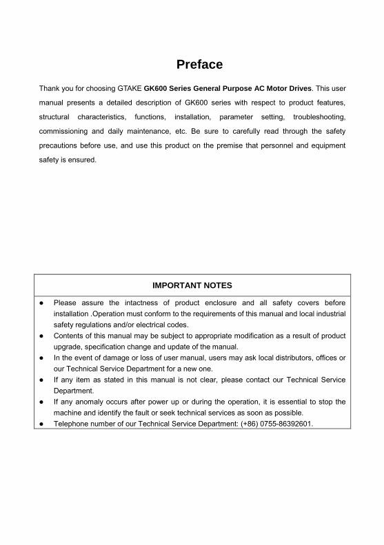
f) GK600-4T560G ~ GK600-4T630G
Fig. 2-4 External dimensions

Chapter 2 Product Information GK600 User Manual
- 20 -
Table 2-3 Appearance, mounting dimensions and weight
Model External and installation dimensions (mm)
Weight (kg) W H D W1 H1 H2 Mounting
hole dia.
GK600-2T0.4B
93 190 152 70 180 172 4.5 1.4 GK600-2T0.75B
GK600-2T1.5B
GK600-2T2.2B 120 245 169 80 233 220 5.5 2.9
GK600-2T3.7B 145 280 179 105 268 255 5.5 3.9
GK600-2T5.5B 190 365 187 120 353 335 6 6.2
GK600-2T7.5B
GK600-2T11(B) 270 475 220 170 460 435 8 15.5
GK600-2T15(B)
GK600-2T18.5(B) 320 568 239 220 544 515 10 24
GK600-2T22(B)
GK600-2T30 385 670 261 260 640 600 12 37
GK600-2T37
GK600-2T45 395 785 291 260 750 705 12 50
GK600-2T55
GK600-2T75 440 900 356 300 865 820 14 66
GK600-2T90 500 990 368 360 950 900 14 88
GK600-2T110 650 1040 406 400 1000 950 14 123
GK600-4T0.75G/1.5LB 93 190 152 70 180 172 4.5 1.4
GK600-4T1.5G/2.2LB
GK600-4T2.2G/3.7LB 120 245 169 80 233 220 5.5 2.9
GK600-4T3.7G/5.5LB
GK600-4T5.5G/7.5LB 145 280 179 105 268 255 5.5 3.9
GK600-4T7.5G/11LB

GK600 User Manual Chapter 2 Product Information
- 21 -
GK600-4T11G/15LB 190 365 187 120 353 335 6 6.2
GK600-4T15G/18.5LB
GK600-4T18.5G/22L(B)
270 475 220 170 460 435 8 15.5 GK600-4T22G/30L(B)
GK600-4T30G/37L(B)
GK600-4T37G/45L(B) 320 568 239 220 544 515 10 24
GK600-4T45G/55L(B)
GK600-4T55G/75L 385 670 261 260 640 600 12 37
GK600-4T75G/90L
GK600-4T90G/110L 395 785 291 260 750 705 12 50
GK600-4T110G/132L
GK600-4T132G/160L 440 900 356 300 865 820 14 66
GK600-4T160G/185L
GK600-4T185G/200L 500 990 368 360 950 900 14 88
GK600-4T200G/220L
GK600-4T220G/250L
650 1040 406 400 1000 950 14 123 GK600-4T250G/280L
GK600-4T280G/315L
GK600-4T315G/355L 815 1300 428 600 1252 1200 14 165
GK600-4T355G/400L
GK600-4T400G/450L
815 1300 428 600 1252 1200 14 165 GK600-4T450G/500L
GK600-4T500G
GK600-4T560G 1100 2000 550 / / / / 515
GK600-4T630G
2.7 External Dimensions of Control Panel
Control panel model of GK600 series general purpose AC motor drive is KBU-BX1 whose appearance and external dimensions are shown in Fig. 2-5.

Chapter 2 Product Information GK600 User Manual
- 22 -
Fig. 2-5 External dimensions of KBU-BX1
2.8 External Dimensions of Control Panel Bracket
A bracket should be provided to support the panel and a hole in the cabinet needs to be opened when the control panel KBU-BX1 needs to be remotely used. Bracket model is KBU-DZ1 whose external dimensions are shown in Fig. 2-6 a). Fig. 2-6 b) shows applicable hole dimensions in the cabinet.
a) External dimensions of KBU-DZ1 b) Hole dimensions in the cabinet
Fig. 2-6 External dimensions of KBU-DZ1 and cabinet hole dimensions
Panel TH Hole WTH
1.2mm 73.2mm
1.5mm 74.4mm
2mm 75.5mm

GK600 User Manual Chapter 3 Installation and Wiring
- 23 -
Chapter 3 Installation and Wiring
3.1 Installation Environment
1) Ambient temperature is in the range of -10℃~ 40℃. 2) Drive should be installed on surface of flame retardant object, with adequate surrounding
space for heat dissipation. 3) Installation should be performed where vibration is less than 5.9m/s2 (0.6g). 4) Protect from moisture and direct sunlight. 5) Protect the cooling fan by avoiding oil, dust and metal particles. 6) Do not expose to an atmosphere with flammable gases, corrosive gases, explosive gases
or other harmful gases. 7) Prevent drilling residues, wire ends and screws falling into drive. 8) Ventilation part of the drive should be installed outside from harsh environment (e.g. textile
facilities with fiber particles and chemical facilities filled with corrosive gases).
3.2 Minimum Mounting Clearances
To ensure favorable heat dissipation, mount the drive upright on a flat, vertical and level surface as per Fig. 3.1. For installation inside cabinet, the product shall be mounted side by side to the greatest extent while adequate surrounding space shall be preserved for favorable heat dissipation.
Fig. 3-1 Minimum mounting clearances of GK600-2T7.5B and below, GK600-4T15G/18.5LB and below
空气流通位置 100mm
100mm空气流通位置30mm30mm
Vent clearance
Vent clearance

Chapter 3 Installation and Wiring GK600 User Manual
- 24 -
ATTENTION: Remove dust covers when mounting a drive GK600-2T7.5B/GK600-4T15G/18.5LB or below. If several drives are mounted in one cabinet, parallel side-by-side mounting is recommended.
Fig. 3-2 Minimum mounting clearances of GK600-2T11(B) and above, GK600-4T18.5G/22L(B) and above
ATTENTION: When mounting a drive GK600-2T11(B) / GK600-4T18.5G/22L(B) or above, the minimum mounting clearances as set forth in Table 3-1 should be assured. In case several drives are mounted in one cabinet, parallel side-by-side mounting is recommended.
Table 3-1 Requirement of minimum mounting clearances
Drive model Mounting clearances (mm)
A B
GK600-2T11(B) ~ GK600-2T22(B)
GK600-4T18.5G/22L(B) ~ GK600-4T45G/55L(B) ≥50 ≥200
GK600-2T30 ~ GK600-2T110
GK600-4T55G/75L(B) ~ GK600-4T500G ≥50 ≥300
空气流通位置
B
空气流通位置
B
A A
Vent clearance
Vent clearance

GK600 User Manual Chapter 3 Installation and Wiring
- 25 -
3.3 Remove & Mount Control Panel and Cover
3.3.1 Remove and Mount Control Panel
Remove control panel Press the buckle of control panel as indicated by number "1" in Fig. 3-3, then pull the panel out to release as indicated by "2".
Mount control panel Slightly slant the panel in the direction as indicated by number "1" in Fig. 3-4 and align it to clamping port at lower part of panel bracket, then press it in as indicated by "2". When a "click" sound heard, it indicates clamping has been properly made.
Fig. 3-3 Remove the control panel Fig. 3-4 Mount the control panel
3.3.2 Open & Mount the Covers of GK600-2T0.4B ~ GK600-2T7.5B, and
GK600-4T0.75G/1.5LB ~ GK600-4T15G/18.5LB
Remove the control panel
Use the remove method as stated in Section 3.3.1. Open the cover
Method 1: loosen the captive cover screws as shown in Fig. 3-5 a) (provided only for 11/15kW model), hold the left and front sides of middle housing with left hand, put the right thumb into the buckle and press tightly on cover with the other four fingers, pull the lower part of the cover out to release, as indicated by number "2". Method 2: loosen the captive cover screws, as indicated by number "1" in Fig. 3-5 b) (provided only for 11/15kW model), use a sizeable slotted screwdriver to push the buckle slightly at the lower part of the cover to make buckle naturally off the groove, as indicated by "2", pull the cover out to release, as indicated by number "3".
1
212

Chapter 3 Installation and Wiring GK600 User Manual
- 26 -
a) Method 1 b) Method 2
Fig. 3-5 Open the cover
Mount the cover
On the completion of wiring, insert the buckle at higher part of the cover into the grooves at middle housing as indicated by number "1" in Fig. 3-6, then push in the lower part of the cover as indicated by "2". When a "click" sound heard, it indicates clamping has been properly made. Tighten the screws (provided only for 11/15kW model) in buckle grooves as finish.
Fig. 3-6 Mount the cover
Mount the control panel
Use the mounting method as stated in Section 3.3.1.
ATTENTION: Be sure to remove the control panel before opening the cover and mount the cover before mounting the control panel.
1
1
2
1 1
螺丝刀Screwdriver

GK600 User Manual Chapter 3 Installation and Wiring
- 27 -
3.3.3 Open & Mount the Covers of GK600-2T11(B) and above,
GK600-4T18.5G/22L(B) and above
Remove the control panel
Use the remove method as stated in Section 3.3.1. Open the lower cover
Loosen the two captive cover screws at lower part of the lower cover by using cross screwdriver, as indicated by number "1" as shown in Fig. 3-7, then pull the cover out and up as indicated by number "2".
Open the upper cover
Loosen the two captive cover screws at lower part of the lower cover by using cross screwdriver, as indicated by number "3" and “4” as shown in Fig. 3-7, then pull the cover out and up as indicated by number "5".
Fig. 3-7 Open & mount the covers
Mount the upper cover
Insert the upper part of the cover into mounting groove as shown in Fig. 3-8 (left), close the upper cover, use cross screwdriver to tighten the four captive screws, as indicated by number “1” and "2".
Mount the lower cover
Insert the lower cover into upper cover in the direction as indicated by number 3 in Fig. 3-8 (right), close the lower cover and tighten the two captive screws, as indicated by number "4".
11
2
3
44
5 3

Chapter 3 Installation and Wiring GK600 User Manual
- 28 -
Fig. 3-8 Mount the upper and lower covers
Mount the control panel
Use the mounting method as stated in Section 3.3.1.
ATTENTION: Be sure to remove the control panel before opening the cover and mount the cover before mounting the control panel.
1
22
1
3
44

GK600 User Manual Chapter 3 Installation and Wiring
- 29 -
3.4 Configuration of Peripheral Devices
3.4.1 Standard Configuration of Peripheral Devices
Fig. 3-9 Standard configuration of peripheral devices
Output AC Reactor
Braking Resistor
Power Supply
Circuit Breaker or RCD
Contactor
Input AC Reactor
DC Choke
Output Filter
AC Motor Drive
PE
Motor PE
Input Filter

Chapter 3 Installation and Wiring GK600 User Manual
- 30 -
3.4.2 Instructions for Peripheral Devices
Table 3-2 Instructions for peripheral devices
Name Instructions Power supply
Input three-phase AC power supply should be in the range as specified in this manual
Circuit breaker
Purpose: disconnect power supply and protect the equipments in case of abnormal overcurrent occurs Type selection: breaking current of circuit breaker is defined to be 1.5~2 times the rated current of the drive Breaking time characteristic of circuit breaker should be selected based on overload protection time characteristic of the drive
RCD Purpose: since the drive outputs PWM HF chopping voltage, HF leakage current is inevitable Type selection: type B dedicated RCD is recommended
Contactor For safety's sake, do not frequently close and break the contactor since this may bring about equipment faults Do not control the start & stop of the drive directly through switch on and off the contactor since this will result in a reduction on the product life
Input AC reactor or DC choke
Improve power factor Reduce the impact of imbalanced three-phase input AC power supply on the system Suppress higher harmonics and reduce the conducted and radiated interference to peripheral devices Restrict the impact of impulse current on rectifier bridges
Input filter Reduce conducted interference from power supply to the drive, improve the immunity of the drive from noise Reduce conducted and radiated interference of the drive to peripheral devices
Brake unit and
braking resistor
Purpose: consume motor feedback energy to attain quick brake Type selection: Contact GTAKE technical personnel for type selection of brake unit. Refer to type selection of braking resistor in Table 3-3 Type Selection of Peripheral Devices.
Output filter Reduce conducted and radiated interference of the drive to peripheral devices
Output AC reactor
Avoid the motor insulation damage result from harmonic voltage Reduce frequent protection from the drive caused by leakage current In case the cable connecting drive and motor is over 100 meters, output AC reactor recommended
Motor Should match the drive

GK600 User Manual Chapter 3 Installation and Wiring
- 31 -
3.4.3 Selection of Peripheral Devices
Table 3-3 Selection of peripheral devices
■GK600-2TB Single-phase / Three-phase 220V input
Drive model
Single-phase Three-phase Brake resistor Circuit
breaker (A)
Contactor (A)
Circuit breaker
(A)
Contactor (A)
Power (W)
Resistance (Ω)
GK600-2T0.4B 10 9 10 9 100 ≥50
GK600-2T0.75B 16 12 10 9 150 ≥50
GK600-2T1.5B 20 18 16 12 150 ≥40
GK600-2T2.2B 32 25 16 12 250 ≥40
■GK600-2T Three-phase 220V input
Drive model Three-phase Brake resistor
Circuit breaker (A)
Contactor (A) Power
(W) Resistance
(Ω) GK600-2T3.7B 32 25 250 ≥25
GK600-2T5.5B 40 32 400 ≥16
GK600-2T7.5B 50 40 500 ≥16
GK600-2T11(B) 63 50 750 ≥10
GK600-2T15(B) 100 65 1000 ≥8
GK600-2T18.5(B) 100 80 1250 ≥5
GK600-2T22(B) 125 95 1500 ≥5
GK600-2T30 160 150 1800 ≥4
GK600-2T37 225 185 2500 ≥3
GK600-2T45 250 225
Brake chopper should be externally mounted when
needed
GK600-2T55 315 265
GK600-2T75 400 330
GK600-2T90 500 400
GK600-2T110 630 500

Chapter 3 Installation and Wiring GK600 User Manual
- 32 -
■GK600-4TG/L, Three phase 400V input
Drive model Circuit
breaker (A)
Contactor(A) Brake resistor /Brake chopper*
Power (W) Resistance (Ω)
GK600-4T0.75G/1.5LB 0.75G 10 9
150 ≥100 1.5L 10 9
GK600-4T1.5G/2.2LB 1.5G 10 9
150 ≥100 2.2L 10 9
GK600-4T2.2G/3.7LB 2.2G 10 9
300 ≥100 3.7L 16 12
GK600-4T3.7G/5.5LB 3.7G 16 12
450 ≥75 5.5L 20 18
GK600-4T5.5G/7.5LB 5.5G 20 18
500 ≥75 7.5L 32 25
GK600-4T7.5G/11LB 7.5G 32 25
500 ≥75 11L 40 32
GK600-4T11G/15LB 11G 40 32
800 ≥30 15L 50 40
GK600-4T15G/18.5LB 15G 50 40
1000 ≥25 18.5L 63 50
GK600-4T18.5G/22L(B) 18.5G 63 50
1300 ≥16 22L 63 50
GK600-4T22G/30L(B) 22G 63 50
1500 ≥16 30L 100 65
GK600-4T30G/37L(B) 30G 100 65
2000 ≥16 37L 100 80
GK600-4T37G/45L(B) 37G 100 80
2500 ≥10 45L 125 95
GK600-4T45G/55L(B) 45G 125 95
3000 ≥10 55L 160 150
GK600-4T55G/75L(B) 55G 160 150
3600 ≥8 75L 225 185
GK600-4T75G/90L(B) 75G 225 185
5000 ≥5 90L 250 225
GK600-4T90G/110L 90G 250 225
Brake chopper should be
externally mounted when
needed
110L 315 265
GK600-4T110G/132L 110G 315 265 132L 350 330
GK600-4T132G/160L 132G 350 330 160L 400 330
GK600-4T160G/185L 160G 400 330 185L 500 400

GK600 User Manual Chapter 3 Installation and Wiring
- 33 -
GK600-4T185G/200L 185G 500 400
Brake chopper should be
externally mounted when
needed
200L 500 400
GK600-4T200G/220L 200G 500 400 220L 630 500
GK600-4T220G/250L 220G 630 500 250L 630 500
GK600-4T250G/280L 250G 630 500 280L 800 630
GK600-4T280G/315L 280G 800 630 315L 800 630
GK600-4T315G/355L 315G 800 630 355L 1000 800
GK600-4T355G/400L 355G 1000 800 400L 1250 800
GK600-4T400G/450L 400G 1250 800 450L 1250 1000
GK600-4T450G/500L 450G 1250 1000 500L 1600 1000
GK600-4T500G 1600 1000 GK600-4T560G 1600 1250 GK600-4T630G 2000 1600 * When brake chopper is built in, the power and resistance value of brake resistor should meet the requirement as
stated in the table. When brake chopper is mounted externally, the power and resistance value of brake resistor
should be in accordance with brake chopper.
** On the premise of fulfilling brake requirement, brake resistance value might be bigger than the minimum value as
stated in the table. Failure to comply may result in damage to the drive. Brake resistors are not built in and need
to be sourced additionally.

Chapter 3 Installation and Wiring GK600 User Manual
- 34 -
3.5 Terminal Configuration
Fig. 3-10 Terminal configuration
3.6 Main Circuit Terminals and Wiring
WARNING
Only qualified personnel familiar with AC motor drives are allowed to implement wiring. Failure to comply may result in equipment damage and/or personnel injury even death.
Wiring should be in strict accordance with this manual, otherwise hazard of electric shock or equipment damage exists.
Make sure input power supply has been completely disconnected before wiring operation. Failure to comply will result in personnel injury even death.
All wiring operations and lines should comply with EMC and national and local industrial safety regulations and/or electrical codes. The conductor diameter should be in accordance with recommendations of this manual. Otherwise, hazard of equipment damage, fire, and/or personnel injury exists.
Since leakage current of the drive may exceed 3.5mA, for safety's sake, the drive and the motor must be grounded so as to avoid hazard of electric shock.
Be sure to perform wiring in strict accordance with the drive terminal marks. Never connect three-phase power supply to output terminals U/T1, V/T2 and W/T3. Failure to comply will result in equipment damage.
Only mount braking resistors at terminals and B2 when needed. When needed, only mount DC reactors at terminals and , and remove the
jumper connected between and . Never connect the jumper and DC reactor to other terminals since this will result in short circuit and equipment damage.
控制回路端子
主回路端子
接地端子
Control circuit terminals
Main circuit terminals
+ 2/B1+ 1 + 2
+ 1 + 2
Grounding terminals

GK600 User Manual Chapter 3 Installation and Wiring
- 35 -
Wiring screws and bolts for main circuit terminals must be screwed tightly. Failure to comply may result in faults and/or equipment damage.
ATTENTION
Signal wires should be away from main power lines to the best of possibility. In the event that this cannot be ensured, vertical cross arrangement should be adopted, reducing EMI interference to the signal wires as much as possible.
In case the motor cable exceeds 100m, an appropriate output reactor should be mounted.
3.6.1 Main Circuit Terminals of GK600-2T0.4B ~ GK600-2T1.5B, and
GK600-4T0.75G/1.5LB ~ GK600-4T1.5G/2.2LB
Terminal marks Designation and function of terminals
L1/L、L2、L3/N Single / Three-phase AC input terminals (Connect L1/L, L3/N when use single phase input)
/B1、B2 Braking resistor connection terminals
/B1、 DC input terminals
U/T1、V/T2、W/T3 Three-phase AC output terminals Ground terminal PE
+
+ -

Chapter 3 Installation and Wiring GK600 User Manual
- 36 -
3.6.2 Main Circuit Terminals of GK600-2T2.2B ~ GK600-2T37,
GK600-4T2.2G/3.7LB ~ GK600-4T75G/90L(B)
* Drives GK600-4T18.5G/22L~GK600-4T75G/90L without “B” in the model number, have no built-in brake choppers
as factory default. Therefore, brake resistor connected between B1 and B2 terminals is invalid.
Terminal marks Designation and function of terminals
R/L1, S/L2, T/L3 Three-phase AC input terminals
, DC reactor connection terminals. Connected with a
jumper as factory default
, B2 Built-in brake unit connection terminals*
, DC input terminals of externally mounted brake unit
, DC power supply input terminals
U/T1, V/T2, W/T3 Three-phase AC output terminals
Ground terminal PE
-
+ 1 + 2/B1
+ 2/B1
+ 2/B1 -
+ 1

GK600 User Manual Chapter 3 Installation and Wiring
- 37 -
3.6.3 Main Circuit Terminals of GK600-2T45 ~ GK600-2T110,
GK600-4T90G/110L ~ GK600-4T500G
*GK600-4T90G/110L~GK600-4T500G have external-mounted DC reactor in shipment as default. Be sure to connect
the DC reactor between terminal and , or there will be no display when applying power on the drives.
3.6.4 Main Circuit Terminals of GK600-4T560G ~ GK600-4T630G
Terminal marks Designation and function of terminal
R/L1、S/L2、T/L3 Three-phase AC input terminals
, DC reactor connection terminals. Connected with a
jumper as factory default *
, DC input terminals of external- mounted brake unit
, DC power supply input terminals
U/T1, V/T2, W/T3 Three-phase AC output terminals
Ground terminal PE
Terminal marks Designation and function of terminals
R/L1, S/L2, T/L3 Three-phase AC input terminals U/T1, V/T2, W/T3 Three-phase AC output terminals
Ground terminal PE
+ 1 -
+ 2 -
+ 1 + 2
+ 1 + 2

Chapter 3 Installation and Wiring GK600 User Manual
- 38 -
3.6.5 Terminal Screw and Wiring Requirement
Table 3-4 Terminal screw and wiring requirement
■GK600-2TB Single-phase / Three-phase 220V input
Drive model
Power terminal Ground terminal
Cable requirement
(mm2) Screw
Torque (kgf.cm)
Cable requirement
(mm2) Screw
Torque (kgf.cm)
GK600-2T0.4B 2.5 M3.5 10±0.5 2.5 M3.5 10±0.5
GK600-2T0.75B 2.5 M3.5 10±0.5 2.5 M3.5 10±0.5
GK600-2T1.5B 2.5 M3.5 10±0.5 2.5 M3.5 10±0.5
GK600-2T2.2B 2.5 M4 14±0.5 2.5 M4 14±0.5 ■GK600-2T Three-phase 220V input
Drive model
Power terminal Ground terminal
Cable requirement
(mm2) Screw
Torque (kgf.cm)
Cable requirement
(mm2) Screw
Torque (kgf.cm)
GK600-2T3.7B 4 M4 14±0.555
4 M4 14±0.5
GK600-2T5.5B 4 M4 28±0.5 4 M5 28±0.5
GK600-2T7.5B 6 M5 28±0.5 6 M5 28±0.5
GK600-2T11(B) 10 M6 48±0.5 10 M6 48±0.5
GK600-2T15(B) 16 M6 48±0.5 16 M6 48±0.5
GK600-2T18.5(B) 25 M8 120±0.55
16 M8 120±0.5
GK600-2T22(B) 25 M8 120±0.5 16 M8 120±0.5
GK600-2T30 50 M10 250±0.5 25 M8 120±0.5
GK600-2T37 70 M10 250±0.5 35 M8 120±0.5
GK600-2T45 95 M12 440±0.5 50 M12 440±0.5
GK600-2T55 120 M12 440±0.5 70 M12 440±0.5
GK600-2T75 150 M12 440±0.5 95 M12 440±0.5
GK600-2T90 185 M12 440±0.5 95 M12 440±0.5
GK600-2T110 240 M16 690±0.5 120 M16 690±0.5
GK600 User Manual Chapter 3 Installation and Wiring
- 39 -
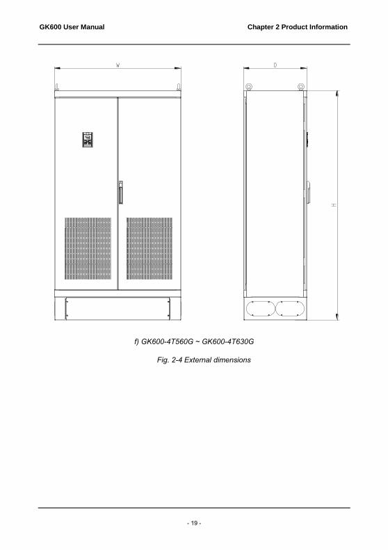
■GK600-4TG/L Three-phase 400V input
Drive model
Power terminal Ground terminal
Cable requiremen
t (mm2) Screw
Torque (kgf.cm)
Cable requirement (mm2)
Screw Torque (kgf.cm)
GK600-4T0.75G/1.5LB 0.75G 2.5 M3.5 10±0.5
2.5 M3.5 10±0.5
1.5L 2.5 2.5
GK600-4T1.5G/2.2LB 1.5G 2.5
M3.5 10±0.5 2.5
M3.5 10±0.5 2.2L 2.5 2.5
GK600-4T2.2G/3.7LB 2.2G 2.5 M4 14±0.5
2.5 M4 14±0.5
3.7L 2.5 2.5
GK600-4T3.7G/5.5LB 3.7G 2.5
M4 14±0.5 2.5
M4 14±0.5 5.5L 2.5 2.5
GK600-4T5.5G/7.5LB 5.5G 2.5 M4 14±0.5
2.5 M4 14±0.5
7.5L 4 4
GK600-4T7.5G/11LB 7.5G 4
M4 14±0.5 4
M4 14±0.5 11L 4 4
GK600-4T11G/15LB 11G 4 M5 28±0.5
4 M4 14±0.5
15L 6 6
GK600-4T15G/18.5LB 15G 6
M5 28±0.5 6
M4 14±0.5 18.5L 10 10
GK600-4T18.5G/22L(B) 18.5G 10 M6 48±0.5
10 M6 48±0.5
22L 10 10
GK600-4T22G/30L(B) 22G 10
M6 48±0.5 10
M6 48±0.5 30L 16 16
GK600-4T30G/37L(B) 30G 16 M6 48±0.5
16 M6 48±0.5
37L 25 16
GK600-4T37G/45L(B) 37G 25
M8 120 ±0.5
16 M8 120±0.5
45L 35 16
GK600-4T45G/55L(B) 45G 35 M8
120 ±0.5
16 M8 120±0.5
55L 50 25
GK600-4T55G/75L(B) 55G 50
M10 250 ±0.5
25 M8 120±0.5
75L 70 35
GK600-4T75G/90L(B) 75G 70 M10
250 ±0.5
35 M8 120±0.5
90L 95 50
GK600-4T90G/110L 90G 95
M12 440 ±0.5
50 M12 440±0.5
110L 120 70

Chapter 3 Installation and Wiring GK600 User Manual
- 40 -
Drive model
Power terminal Ground terminal
Cable requiremen
t (mm2) Screw
Torque (kgf.cm)
Cable requirement (mm2)
Screw Torque (kgf.cm)
GK600-4T110G/132L 110G 120 M12
440 ±0.5
70 M12 440±0.5
132L 120 70
GK600-4T132G/160L 132G 120
M12 440 ±0.5
70 M12 440±0.5
160L 150 95
GK600-4T160G/185L 160G 150 M12
440 ±0.5
95 M12 440±0.5
185L 185 95
GK600-4T185G/200L 185G 185
M12 440 ±0.5
95 M12 440±0.5
200L 185 95
GK600-4T200G/220L 200G 185 M12
440 ±0.5
95 M12 440±0.5
220L 240 120
GK600-4T220G/250L 220G 240
M16 690 ±0.5
120 M16 690±0.5
250L 120x2 120
GK600-4T250G/280L 250G 120x2 M16
690 ±0.5
120 M16 690±0.5
280L 120x2 120
GK600-4T280G/315L 280G 120x2
M16 690 ±0.5
120 M16 690±0.5
315L 150x2 150
GK600-4T315G/355L 315G 150x2 M16
690 ±0.5
150 M16 690±0.5
355L 185x2 95x2
GK600-4T355G/400L 355G 185x2
M16 690 ±0.5
95x2 M16 690±0.5
400L 240x2 120x2
GK600-4T400G/450L 400G 240x2 M16
690 ±0.5
120x2 M16 690±0.5
450L 240x2 120x2
GK600-4T450G/500L 450G 240x2
M16 690 ±0.5
120x2 M16 690±0.5
500L 240x2 120x2
GK600-4T500G 240x2 M16 690 ±0.5
120x2 M16 690±0.5
GK600-4T560G 300x2 M16 690 ±0.5
150x2 M16 690±0.5
GK600-4T630G 300x2 M16 690 ±0.5
150x2 M16 690±0.5

GK600 User Manual Chapter 3 Installation and Wiring
- 41 -
3.7 Control Terminal Wiring
WARNING
Only qualified personnel familiar with AC motor drives are allowed to implement wiring. Failure to comply may result in equipment damage and/or personnel injury even death.
Wiring should be in strict accordance with this manual, otherwise hazard of electric shock or equipment damage exists.
Make sure input power supply has been completely disconnected before wiring operation. Failure to comply will result in personnel injury even death.
All wiring operations and lines should comply with EMC and national and local industrial safety regulations and/or electrical codes. The conductor diameter should be in accordance with recommendations of this manual. Otherwise, hazard of equipment damage, fire, and/or personnel injury exists.
Screws or bolts for terminal wiring must be screwed tightly. AC 220V signal is prohibited from connecting to terminals other than control terminals
RA, RB and RC.
ATTENTION
Signal wires should be away from main power lines to the best of possibility. If this cannot be ensured, vertical cross arrangement should be adopted, reducing EMI interference to the signal wires as much as possible.
The encoder must be provided with shielded cables whose shielded layer must be properly grounded.

Chapter 3 Installation and Wiring GK600 User Manual
- 42 -
3.7.1 Control Board Diagram
Fig. 3-11 Control board diagram
OFF
ONAI1 AO1485
I
VV
I
S2S1 S3
主信号接口
操作面板485接口 扩展卡接口
用户信号端子
端子通讯
终端
电阻
选
择
模
拟量
输入 1
电压
电
流选
择
模
拟量
输出 1
电压电
流
选
择
Control panel 485 interface Option board interface
Main signal interface
S1: Terminal resistor selection for terminal communication
S2: Analog input 1 voltage/current option
S3: Analog output 1 voltage/current option
User signal terminal
GK600 User Manual Chapter 3 Installation and Wiring
- 43 -
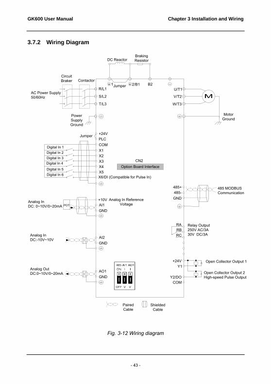
3.7.2 Wiring Diagram
M
DC Reactor
Jumper
Braking Resistor
Motor Ground
R/L1
S/L2
T/L3
U/T1
V/T2
W/T3
Power Supply Ground
++ 1 2/B1 B2
Circuit Braker Contactor
AC Power Supply50/60Hz
+24VPLC
X1X2X3X4X5X6/DI (Compatible for Pulse In)
COMDigital In 1Digital In 2Digital In 3Digital In 4Digital In 5Digital In 6
RARBRC
+24VY1
Y2/DOCOM
+10V AI1GND
Relay Output250V AC/3A30V DC/3A
Open Collector Output 1
Open Collector Output 2High-speed Pulse Output
Option Board InterfaceCN2
Jumper
Analog In Reference VoltagePOT
AI2GND
485 MODBUS Communication
485+485-
AO1GND
GND
Paired Cable
Shielded Cable
Analog InDC: 0~10V/0~20mA
Analog InDC:-10V~10V
Analog OutDC:0~10V/0~20mA
-
Fig. 3-12 Wiring diagram

Chapter 3 Installation and Wiring GK600 User Manual
- 44 -
3.8 Control Terminal Specification
Table 3-5 Control terminal specification
Category Terminal Terminal designation
Specification
Analog input
+10V Analog input
reference voltage
10.3V ±3% Maximum output current 25mA The resistance of external potentiometer should be larger than 400Ω
GND Analog ground Isolated from COM interiorly
AI1 Analog input 1
0~20mA: input impedance - 500Ω, maximum input current - 25mA 0~10V: input impedance - 22kΩ, maximum input voltage - 12.5V Switch S2 on control board for jumping from 0~20mA and 0~10V, factory default: 0~10V
AI2 Analog input 2 -10V~10V: input impedance - 25kΩ
Range: -12.5V~+ 12.5V
Analog output
AO1 Analog output 1
0~20mA: impedance - 200Ω~500Ω
0~10V: impedance ≥ 10k Switch S3 on control board for jumping between 0~20mA and 0~10V, factory default: 0~10V
GND Analog ground Isolated from COM interiorly
Digital input
+24V +24V 24V±10%, Isolated from GND interiorly
Maximum load - 200mA
PLC Digital input
Common terminal
Used for switching between high and low levels, short-circuited with +24V when delivery, i.e. low value of digital input valid External power input
COM +24V ground Isolated from GND interiorly
X1~X5 Digital input Terminals 1~5
Input: 24VDC, 5mA
Range of frequency: 0~200Hz
Range of voltage: 10V~30V
X6/DI Digital input/pulse input
Digital input: same as X1~X5 Pulse input: 0.1Hz~50kHz; range of voltage: 10-30V
Digital output Y1 Open collector
output Range of voltage: 0~24V
Range of current: 0~50mA

GK600 User Manual Chapter 3 Installation and Wiring
- 45 -
Category Terminal Terminal designation
Specification
Digital output Y2/DO Open collector
out / Pulse out Open collector output: same as Y1
Pulse output: 0~50kHz;
Relay output RA/RB/RC Control board
relay output RA-RB: NC; RA-RC: NO
Contact capacity: 250VAC/3A, 30VDC/3A
Terminal 485
Interface
485+ 485 differential signal +
Rate: 4800/9600/19200/38400/57600/115200bps
485− 485 differential signal -
Maximum distance - 500m (standard network cable used)
GND 485
communication shield grounding
Isolated from COM interiorly
Control panel 485
interface
CN4 Control panel 485 interface
Maximum communication distance is 15m when connected to Control panel
Use standard network cable
3.9 Control Terminal Usage
3.9.1 Lay-out of Control Terminals
Fig. 3-13 Lay-out of control terminals
3.9.2 Control Terminal Screw and Wiring Requirement
Table 3-6 Terminal screw and wiring specification
Cable type Cable requirement (mm2) Screw Torque (kgf.cm)
Shielded cable 1.0 M3 5±0.5
3.9.3 Instructions of Analog Input/Output Terminals
Being particularly vulnerable to noise, analog input & output signal cables should be as short as possible, shielded, and their shielded layers should be properly grounded close to the side of drive. The cables should not exceed 20m.

Chapter 3 Installation and Wiring GK600 User Manual
- 46 -
Control cables shall be kept no less than 20cm away from main circuit and strong current lines (e.g. power lines, motor lines, relay lines and contactor lines) and should not be arranged in parallel with strong current lines. In case it is inevitable to intersect strong current line, vertical wiring is recommended to avoid drive faults as a result of noise.
Where analog input & output signals are severely interfered, the side of analog signal source should be provided with filter capacitor or ferrite core.
3.9.4 Instructions of Digital Input/Output Terminals
Digital input & output signal cables should be as short as possible, shielded, and their shielded layers should be properly grounded close to the side of drive. The cables should not exceed 20m. When active drive is selected, take necessary filtering measures against power crosstalk, for which dry contact control is recommended.
Control cables shall be kept no less than 20cm away from main circuit and strong current lines (e.g. power lines, motor lines, relay lines and contactor lines) and should not be arranged in parallel with strong current lines. In case it is inevitable to intersect strong current line, vertical wiring is recommended to avoid drive faults as a result of noise. Operating instructions for switching value input terminal
Instructions of digital input terminal
Dry contact
1
6
X1
X6/DI
COM
+24V
PLC
+3.3V
GND
24V
DriveExternal Controller
Shielded Cable
Near-end Ground
+-
Jumper
OC
+3.3V
GND
+-OC
Fig. 3-14 Internal power supply dry contact

GK600 User Manual Chapter 3 Installation and Wiring
- 47 -
1
6
X1
X6/DI
COM
+24V
PLC
+3.3V
GND
24V
DriveExternal Controller
Shielded Cable
Near-end Ground
+-OC
+3.3V
GND
+-OC
+-
20~30V
Fig. 3-15 External power supply dry contact
ATTENTION: When external power supply is used, the jumper between +24V and PLC must be removed.
Otherwise, it may result in equipment damage. The voltage range of external power supply should be DC20~30V. Otherwise, normal
operation could not be assured and/or result in equipment damage.

Chapter 3 Installation and Wiring GK600 User Manual
- 48 -
Open collector NPN connection
X1
X6/DI
COM
+24V
PLC
+3.3V
GND
24V
Drive
Shielded Cable
Near-end Ground
+-
Jumper
OC
+3.3V
GND
+-OC
1
6
External Controller
Fig. 3-16 Internal power supply open collector NPN connection
X1
X6/DI
COM
+24V
PLC
+3.3V
GND
24V
Drive
Shielded Cable
Near-end Ground
+-OC
+3.3V
GND
+-OC
+-
20~30V
1
6
External Controller
Fig. 3-17 External power supply open collector NPN connection
ATTENTION: When external power supply is used, the jumper between +24V and PLC must be removed. The voltage range of external power supply should be DC20~30V, otherwise normal operation could not be assured and/or hazard of equipment damage exists.

GK600 User Manual Chapter 3 Installation and Wiring
- 49 -
Open collector PNP connection
X1
X6/DI
COM
+24V
PLC+3.3V
GND
24V
Drive
Shielded Cable
Near-end Ground
+-Jumper
OC
+3.3V
GND
+-OC
1
6
External Controller
Fig. 3-18 Internal power supply open collector PNP connection
ATTENTION: When PNP connection is adopted, it is necessary to remove the jumper between +24V and PLC, and connect the jumper to PLC and COM.
X1
X6/DI
COM
+24V
PLC
+3.3V
GND
24V
Drive
Shielded Cable
Near-end Ground
+-OC
+3.3V
GND
+-OC
20~30V
1
6
External Controller
+ -
Fig. 3-19 External power supply open collector PNP connection
ATTENTION:
When external power supply is used, the jumper between +24V and PLC must be removed. The voltage range of external power supply should be DC20~30V. Otherwise, normal operation could not be assured and/or hazard of equipment damage exists.

Chapter 3 Installation and Wiring GK600 User Manual
- 50 -
Instructions of digital output terminal
Instructions of Y1 and Y2/DO output terminals
a) Internal power supply b) External power supply
Fig. 3-20 Wiring when Y1 and Y2/DO output with pull-up resistor
ATTENTION: When set to be pulse output, Y2/DO terminal shall output 0~50kHz pulse signal.
a) Internal power supply b) External power supply
Fig. 3-21 Wiring when Y1 and Y2/DO drive relay
ATTENTION: When relay coil voltage is lower than 24V, a resistor as voltage divider should be mounted between relay and output terminal, based on coil impedance.
Wiring instruction of relay output terminal
Control board of GK600 series drive is provided with a group of programmable relay dry contact outputs. RA/RB/RC are relay contacts. RA and RB are normally closed, while RA and RC are normally open. See parameter C1-02 for details.
ATTENTION: In case inductive load (e.g. electromagnetic relay or contactor) is to be driven, a surge voltage absorbing circuit such as RC absorbing circuit (note that its leakage current shall be less than holding current of controlled contactor or relay), piezoresistor or fly-wheel diode etc. shall be mounted (be sure to pay close attention to polarity in case of DC electromagnetic circuit). Absorbing devices should be mounted close to the ends of relay or contactor.
Y1、Y2/DO
COM
+24V
+5V
24V
Drive
OC
Y1、Y2/DO
COM
+24V
+5V
24V
Drive
OC
=30VPull-up Resistor
Pull-up Resistor
Y1、Y2/DO
COM
+24V
+5V
24V
Drive
OC
Y1、Y2/DO
COM
+24V
+5V
24V
Drive
OC
=30VRelay Relay
GK600 User Manual Chapter 3 Installation and Wiring
- 51 -
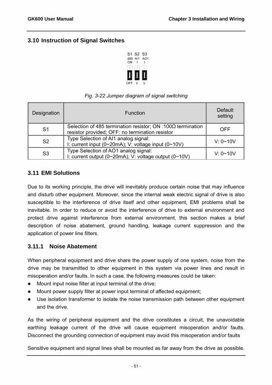
3.10 Instruction of Signal Switches
Fig. 3-22 Jumper diagram of signal switching
3.11 EMI Solutions
Due to its working principle, the drive will inevitably produce certain noise that may influence and disturb other equipment. Moreover, since the internal weak electric signal of drive is also susceptible to the interference of drive itself and other equipment, EMI problems shall be inevitable. In order to reduce or avoid the interference of drive to external environment and protect drive against interference from external environment, this section makes a brief description of noise abatement, ground handling, leakage current suppression and the application of power line filters.
3.11.1 Noise Abatement
When peripheral equipment and drive share the power supply of one system, noise from the drive may be transmitted to other equipment in this system via power lines and result in misoperation and/or faults. In such a case, the following measures could be taken: Mount input noise filter at input terminal of the drive; Mount power supply filter at power input terminal of affected equipment; Use isolation transformer to isolate the noise transmission path between other equipment
and the drive.
As the wiring of peripheral equipment and the drive constitutes a circuit, the unavoidable earthing leakage current of the drive will cause equipment misoperation and/or faults. Disconnect the grounding connection of equipment may avoid this misoperation and/or faults
Sensitive equipment and signal lines shall be mounted as far away from the drive as possible.
Designation Function Default setting
S1 Selection of 485 termination resistor; ON :100Ω termination resistor provided; OFF: no termination resistor OFF
S2 Type Selection of AI1 analog signal: I: current input (0~20mA); V: voltage input (0~10V) V: 0~10V
S3 Type Selection of AO1 analog signal: I: current output (0~20mA); V: voltage output (0~10V) V: 0~10V
ON
OFF
AI1 AO1485
V
II
V
S2S1 S3

Chapter 3 Installation and Wiring GK600 User Manual
- 52 -
Signal lines should be provided with shielded layer and reliably grounded. Alternatively, signal cable could be put into metallic conduits between which the distance shall be no less than 20cm, and shall be kept as far away from the drive, its peripheral devices, and cables as possible. Never make signal lines in parallel with power lines or bundle them up.
Signal lines must orthogonally cross power lines if this cross is inevitable. Motor cables shall be placed in thick protective screen like more than 2mm-thick pipelines or buried in cement groove, also, power lines can be put into metallic conduit and grounded well with shielded cables.
Use 4-core motor cables of which one is grounded at close side of the drive and the other side is connected to motor enclosure.
Input and output terminals of the drive are respectively equipped with radio noise filter and linear noise filter. For example, ferrite common mode choke can restrain radiation noise of power lines.
3.11.2 Grounding
Recommended ground electrode is shown in the figure below:
Fig. 3-23 Grounding
Use to the fullest extent the maximum standard size of grounding cables to reduce the impedance of grounding system.
Grounding wires should be as short as possible. Grounding point shall be as close to the drive as possible.
One wire of 4-core motor cables shall be grounded at the drive side and connected to grounding terminal of motor at the other side. Better effect will be achieved if motor and drive are provided with dedicated ground electrodes.
When grounding terminals of various parts of system are linked together, leakage current turns into a noise source that may influence other equipment in the system, thus, grounding terminals of the drive and other vulnerable equipment should be separated. Grounding cable shall be kept away from inlet & output of noise-sensitive equipment.
3.11.3 Leakage Current Suppression
Leakage current passes through the line-to-line and ground distributed capacitors at input & output sides of drive, and its size is associated with the capacitance of distributed capacitor and
变频器 电机
PE
Drive Motor

GK600 User Manual Chapter 3 Installation and Wiring
- 53 -
the switching frequency. Leakage current is classified into ground leakage current and line-to-line leakage current.
Ground leakage current not only circulates inside drive system, but may also influence other equipment via ground loop. Such a leakage current may result in malfunction of RCD and other equipment. The higher the switching frequency of drive is, the bigger the ground leakage current will be. The longer the motor cables and the bigger the parasitic capacitance are, the bigger the ground leakage current will be. Therefore, the most immediate and effective method for suppression of ground leakage current is to reduce the switching frequency and minimize the length of motor cables.
The higher harmonics of line-to-line leakage current that passes through between cables at output side of drive will accelerate the aging of cables and may bring about malfunction of other equipment. The higher the switching frequency of drive is, the bigger the line-to-line leakage current will be. The longer the motor cables and the bigger the parasitic capacitance are, the bigger the line-to-line leakage current will be. Therefore, the most immediate and effective method for suppression of ground leakage current is to reduce the switching frequency and minimize the length of motor cable. Line-to-line leakage current can also be effectively suppressed by mounting additional output reactors.
3.11.4 Use of Power Supply Filter
Since AC drives may generate strong interference and are also sensitive to outside interference, power supply filters are recommended. Pay close attention to the following instructions during the use: Enclosure of the filter needs to be reliably grounded; Input lines of the filter shall be kept as far away from output lines as possible so as to avoid
mutual coupling; Filter shall be as close to the drive side as possible; Filter and drive must be connected to the same common ground.

Chapter 4 Operation and Run Instructions GK600 User Manual
- 54 -
Chapter 4 Operation and Run Instructions
4.1 Operation of Control Panel
As a human-machine interface, control panel is the main part for the drive to receive command and display parameters.
Fig. 4-1 Control panel
4.1.1 Key Functions on Control Panel
On the control panel there are 8 keys whose functions are as shown in Table 4-1.
Table 4-1 Key functions on control panel
Symbol Key name Meaning
Enter key 1) Parameter edition enter 2) Confirmation of parameter settings 3) Confirmation of MF key function
Escape key 1) Return function 2) Invalid parameter edit value
Increase key
1) Increase of selected bit of parameter value 2) Increase of selected bit of parameter value 3) Increase of set frequency
Decrease key
1) Decrease of selected bit of parameter 2) Decrease of selected bit of parameter value 3) Decrease of set frequency
Shift key
1) Selection of parameter bit 2) Selection of parameter value bit 3) Selection of stop/run status display parameter value 4) Fault status switches to parameter value display status
Run key Run

GK600 User Manual Chapter 4 Operation and Run Instructions
- 55 -
Symbol Key name Meaning
Stop/reset key 1) Stop 2) Fault reset
Multi-function key See Table 4-2 " MF key function definition"
Table 4-2 MF key function definition
L0-00 set
value Function of MF key Meaning
0 Disabled MF key disabled 1 Forward JOG Forward JOG function 2 Reverse JOG Reverse JOG function
3 Forward/Reverse switch
Running direction forward and reverse switching
4 Emergency STOP 1 Press to STOP, with ramp-down time b2-09
5 Emergency STOP 2
Coast to stop, the drive cuts off output
6 Run command setting mode switch
Control panel control -> Terminal control -> Communication control -> Control panel control, press
to confirm within 5 seconds

Chapter 4 Operation and Run Instructions GK600 User Manual
- 56 -
4.1.2 Control Panel Indicators
Control panel is furnished with 7 indicators whose descriptions are as below
Table 4-3 Description of indicators
Indicator Designation Meaning
Hz Frequency indicator
ON: currently displayed parameter value is running frequency or the current parameter unit is frequency Flash: currently displayed parameter value is set frequency
A Current indicator ON: currently displayed parameter value is current V Voltage indicator ON: currently displayed parameter value is voltage
Hz+A Running speed indicator
ON: currently displayed parameter value is running speed Flash: currently displayed parameter value is setting speed
A+V Percentage indicator ON: currently displayed parameter value is a percentage value
All OFF No unit No unit
MON Run command setting mode indicator
ON: Control panel OFF: Terminal Flash: Communication
RUN Run status indicator ON: Run OFF: Stop Flash: Stopping
FWD Forward indicator
ON: If the drive in stop status, forward command enabled. If the drive in run status, the drive is running forward Flash: Forward is being transferred to reverse
REV Reverse indicator
ON: If the drive in stop status, reverse command enabled. If the drive in run status, the drive is running reversely. Flash: Reverse is being transferred to forward
4.1.3 Control Panel Display Status
Control panel indicates eight types of status, STOP parameters display, Run parameters display, Fault display, parameter number edition, parameter setting, Password authentication, Direct frequency modification and Prompt message. The operation relating to these statuses and the switching among these statuses is described as follows.

GK600 User Manual Chapter 4 Operation and Run Instructions
- 57 -
4.1.3.1 Display of STOP Parameters
The drive normally gets into STOP parameters display once run has been stopped. By default, set frequency is displayed in such a status, and other parameters can be displayed through setting of L1-02 parameters and the key. For example, when users need to check set frequency as well as the values of bus voltage and AI1 value in stop status, set L1-02=0013 (refer to setting method of parameters) and press the key to display the value of bus voltage and then press again to display the value of AI1.
Fig. 4-2 Stop parameter display status (Displaying setting frequency – 50.00Hz)
Run status will be enabled immediately upon receipt of run command in stop status. Press to get into parameter edit status (get into password authentication status if parameter
under password protection). Directly get into frequency modification status when receive UP/DOWN command from terminal, or and pressing on control panel. Switch to fault display status once a fault occurs or an alarm is given.
4.1.3.2 Run Parameter Display Status
In case there is no fault, the drive will get into run parameters display status upon receipt of run command. Default display is run frequency, and other parameters can be displayed through setting of L1-00 and L1-01 and press to shift. For example, in run status, when users need to check bus voltage, motor speed, and input terminals status, please set L1-00= 0084 and L1-01= 0004, and press to shift to the display of bus voltage, then press again to display motor speed, and then press to display input terminals state value.

Chapter 4 Operation and Run Instructions GK600 User Manual
- 58 -
Fig. 4-3 Run parameter display status (Displaying run frequency – 50.00Hz)
Stop status will be enabled immediately upon receipt of stop command in such a status. Press to get into parameter edit status (get into password authentication status if parameter
under password protection). Directly get into frequency modification status when receiving UP/DOWN command from terminal, or pressing or . Switch to fault alarm display status once a fault occurs or an alarm is given.
4.1.3.3 Fault Alarm Display Status
In case a fault occurs or an alarm is given, the drive will get into fault or alarm display status.
Fig. 4-4 Fault or alarm display status (CCL: Contactor act fault)
In such a status, the drive gets into stop status upon receipt of pressing , and would get into parameter edit status when receiving pressing command again (if parameter is under password protection, the drive would get into password authentication status). Directly get into frequency modification status when receiving UP/DOWN command from terminal, or pressing or .

GK600 User Manual Chapter 4 Operation and Run Instructions
- 59 -
4.1.3.4 Parameter Edit Status
Enter parameter edit status immediately upon pressing in STOP status, run parameters display status, and direct frequency modification status. This status could also be entered upon receipt of consecutive twice pressing in fault display status. The drive shall quit current status and be previous status upon receipt of pressing .
Fig. 4-5 Parameter edit status
4.1.3.5 Parameter Value Setting Status
Enter parameter value setting status upon receipt of pressing when in parameter value edit status. When pressing or command is received in such a state, escape parameter edit status.

Chapter 4 Operation and Run Instructions GK600 User Manual
- 60 -
Fig. 4-6 Parameter value setting status (b0-02 is set to 49.83Hz)
4.1.3.6 Password Authentication Status
On condition that parameters are under password protection, users would have to go through password authentication when they want to modify function code parameter value. Only A0-00 is visible in such a state.
Under password protection, the password authentication status will be first entered upon the receipt of pressing in STOP parameter display status, run parameter display status, or direct frequency modification status (refer to the setting method of parameters). It will enter parameter edit status upon the completion of password authentication.
4.1.3.7 Direct Frequency Modification Status
In the status of STOP, fault or run, the drive will enter frequency modification status when terminal UP/DOWN is enabled, or pressing or .
Fig. 4-7 Direct frequency modification status

GK600 User Manual Chapter 4 Operation and Run Instructions
- 61 -
4.1.3.8 Prompt Message Status
Prompt message status shall be displayed upon the completion of some operations. For instance, the "bASIC" prompt message would be displayed upon the completion of parameter initialization.
Fig. 4-8 Prompt message status
Prompt message characters and their meanings are shown as specified in Table 4-4.
Table 4-4 Prompt characters
Prompt
symbol
Meaning Prompt
symbol
Meaning
bASIC When A0-01 is set to 0 CPyb1 Backup parameter value
dISP1 When A0-01 is set to 1 LoAd Parameter upload to control panel
USEr When A0-01 is set to 2 dnLd1 Parameter download from control panel (motor parameter excluded)
ndFLt When A0-01 is set to 3 dnLd2 Parameter download from control panel (motor parameter included)
LoC-1 Control panel locked 1 (full locked) P-SEt Password has been set
LoC-2 Control panel locked 2
(all locked except RUN, STOP/RESET)
P-CLr Password cleared
LoC-3 Control panel locked 3
(all locked except STOP/RESET) TUNE
Motor parameter identification in process

Chapter 4 Operation and Run Instructions GK600 User Manual
- 62 -
LoC-4 Control panel locked 4
(all locked except shift ) LoU Drive undervoltage
PrtCt Control panel protection CLr-F Clear fault record
UnLoC Control panel lock cleared dEFt1 Restore to factory default parameters (motor parameter excluded)
rECy1 Read the backup parameter value to parameter
dEFt2 Restore to factory default parameters (motor parameter included)
Table 4-5 shows meanings of the characters displayed on control panel.
Table 4-5 Meanings of displayed characters
Displayed
character
Character
Meaning
Displayed
character
Character
Meaning
Displayed
character
Character
Meaning
Displayed
character
Character
Meaning
0
A I
T
1
b
J
t
2
C L U
3
c
N
v
4
d
n
y
5
E
o
-
6
F
P
8.
7
G
q
.
8
H
r
9
h S

GK600 User Manual Chapter 4 Operation and Run Instructions
- 63 -
4.1.4 Setting Method of Parameters
4.1.4.1 Parameter System
GK600 series drive parameter group: A0~A1, b0~b2, C0~C4, d0~d5, E0~E1, F0~F3, H0~H1, L0~L1, U0~U1. Each parameter group contains a number of parameters. Parameters are identified by the combination "parameter group character + parameter subgroup number + parameter number". For instance, "F3-07" indicates the seventh parameter at subgroup 3, group F.
4.1.4.2 Parameter Display Structure
Parameters and the parameter values are subject to a two-tier structure. Parameters correspond to first-tier display, while parameter values correspond to second-tier display.
First-tier display shown in Fig. 4-9:
Fig. 4-9 First-tier display of parameter
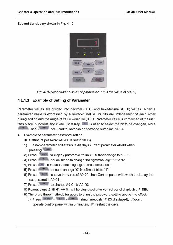
Chapter 4 Operation and Run Instructions GK600 User Manual
- 64 -
Second-tier display shown in Fig. 4-10:
Fig. 4-10 Second-tier display of parameter ("3" is the value of b0-00)
4.1.4.3 Example of Setting of Parameter
Parameter values are divided into decimal (DEC) and hexadecimal (HEX) values. When a parameter value is expressed by a hexadecimal, all its bits are independent of each other during edition and the range of value would be (0~F). Parameter value is composed of the unit, tens place, hundreds and kilobit. Shift Key is used to select the bit to be changed, while
and are used to increase or decrease numerical value.
Example of parameter password setting Setting of password (A0-00 is set to 1006) 1) In non-parameter edit status, it displays current parameter A0-00 when
pressing . 2) Press to display parameter value 0000 that belongs to A0-00; 3) Press for six times to change the rightmost digit "0" to "6"; 4) Press to move the flashing digit to the leftmost bit; 5) Press once to change "0" in leftmost bit to "1"; 6) Press to save the value of A0-00, then Control panel will switch to display the next parameter A0-01; 7) Press to change A0-01 to A0-00; 8) Repeat steps 2) till 6). A0-01 will be displayed after control panel displaying P-SEt; 9) There are three methods for users to bring the password setting above into effect: ① Press + + simultaneously (PrtCt displayed), ②won’t
operate control panel within 5 minutes, ③ restart the drive.

GK600 User Manual Chapter 4 Operation and Run Instructions
- 65 -
Flow chart of user password setting:
Fig. 4-11 Flow chart of user password setting
ATTENTION: User's password is successfully set when step 8 finished, but will not take effect until the completion of step 9.
Password authentication
In non-parameter edit status, press to enter first-tier display A0-00, then press to enter second-tier display 0.0.0.0. Control panel will implement the display of
other parameters only when correct password entered.
Clear password
After successful password authentication, it will access password setting code A0-00. Password can be cleared by writing value 0000 into A0-00 twice.
Example of parameter setting
Example 1: modify upper limit frequency from 600Hz to 50Hz (change b0-09 from 600.00 to 50.00) 1) In non-parameter edit status, press to display current parameter A0-00; 2) Press to move flashing digit to modification bit (A flashes); 3) Press once to change "A" to "b"; 4) Press to move flashing to modification bit (0 in ones place flashing); 5) Press nine times to change "0" to "9"; 6) Press to view the parameter value (600.00) of b0-09; 7) Press to move flashing digit to modification digit (6 flashing); 8) Press six times to change "6" to "0"; 9) Press once to move flashing digit rightwards by one bit;
放弃修改
50.00 50.00 0.0.0.60.0.0.0A0-0050.00ENT ENT ▲
>>
0.0.0.61.0.0.6A0-01A0-00ENT ▲▼
ENT
0.0.0.0 0.0.0.6 0.0.0.6 1.0.0.6
A0-0150.00
A0-00ESC
▲>>▲
ENT
ESC
Escape modification

Chapter 4 Operation and Run Instructions GK600 User Manual
- 66 -
10) Press for five times to change "0" to "5"; 11) Press to save the value (50.00) of b0-09. Then the control panel will
automatically switch to display the next function code (b0-10); 12) Press to exit parameter edit status.
Flow chart is shown below:
Fig. 4-12 Flow chart of upper limit frequency modification
Example 2: user parameter initialization 1) In non-parameter edit status, press to display current parameter A0-00; 2) Press three times to change "0" in the rightmost bit of A0-00 to "3"; 3) Press to display parameter value 0 of A0-03; 4) Press once to change "0" to "2" or "3" ("2" motor parameter excluded, "3"
means motor parameter included); 5) Press to save the value of A0-03.Then control panel will automatically display
parameter A0-00; 6) Press to escape parameter edit status.
Flow chart is shown below:
Fig. 4-13 Flow chart of user parameter initialization
放弃修改
50.00ENT
A0-00 A0-00>>
b0-00▲
>>
b0-00b0-09600.00600.00
000.00 000.00 050.00
b0-09
b0-10
50.00
▲ENT>>
▼
>> ▲
ESC
ENT
ESC
50.00ENT
A0-00 A0-03 0
2或3A0-0050.00
▲ ENT
▲ENTESC
Escape modification
2 or 3
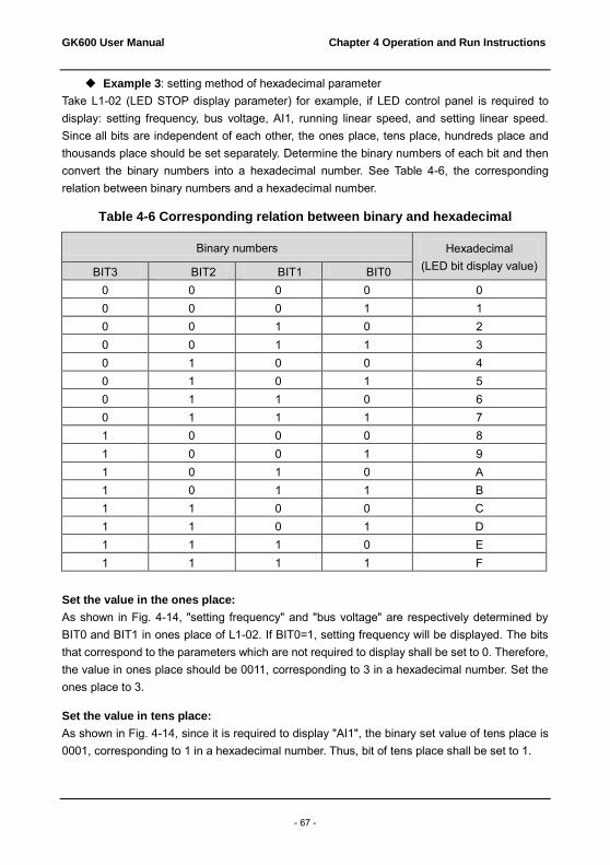
GK600 User Manual Chapter 4 Operation and Run Instructions
- 67 -
Example 3: setting method of hexadecimal parameter Take L1-02 (LED STOP display parameter) for example, if LED control panel is required to display: setting frequency, bus voltage, AI1, running linear speed, and setting linear speed. Since all bits are independent of each other, the ones place, tens place, hundreds place and thousands place should be set separately. Determine the binary numbers of each bit and then convert the binary numbers into a hexadecimal number. See Table 4-6, the corresponding relation between binary numbers and a hexadecimal number.
Table 4-6 Corresponding relation between binary and hexadecimal
Binary numbers Hexadecimal (LED bit display value) BIT3 BIT2 BIT1 BIT0
0 0 0 0 0 0 0 0 1 1 0 0 1 0 2 0 0 1 1 3 0 1 0 0 4 0 1 0 1 5 0 1 1 0 6 0 1 1 1 7 1 0 0 0 8 1 0 0 1 9 1 0 1 0 A 1 0 1 1 B 1 1 0 0 C 1 1 0 1 D 1 1 1 0 E 1 1 1 1 F
Set the value in the ones place:
As shown in Fig. 4-14, "setting frequency" and "bus voltage" are respectively determined by BIT0 and BIT1 in ones place of L1-02. If BIT0=1, setting frequency will be displayed. The bits that correspond to the parameters which are not required to display shall be set to 0. Therefore, the value in ones place should be 0011, corresponding to 3 in a hexadecimal number. Set the ones place to 3.
Set the value in tens place:
As shown in Fig. 4-14, since it is required to display "AI1", the binary set value of tens place is 0001, corresponding to 1 in a hexadecimal number. Thus, bit of tens place shall be set to 1.

Chapter 4 Operation and Run Instructions GK600 User Manual
- 68 -
Set the value in hundreds place:
As shown in Fig. 4-14, the parameter required to display does not involve hundreds place, so the hundreds place shall be set to zero.
Set thousands place:
As shown in Fig. 4-14, since required to display "running linear speed" and "setting linear speed", the binary set value of thousands place shall be 0011 that corresponds to 3 in a hexadecimal number.
To sum up, L1-02 should be set to 3013.
Fig. 4-14 Setting of hexadecimal parameter L1-02
Under parameter setting status, the parameter value cannot be modified if the value has no flashing digit. Possible causes include: 1) The parameter cannot be modified, such as actual detection parameters, running recording
parameters, etc; 2) This parameter cannot be modified in run status but can be changed when motor stopped; 3) Parameter under protection. When parameter A0-02 is set to 1, parameters cannot be
modified as the parameter protection against misoperation enabled. To edit parameter in such a circumstance, it is necessary to set A0-02 to 0 as first step.
4.1.4.4 Lock/Unlock Control Panel
Lock control panel
All or some keys of CONTROL PANEL can be locked by any of the following three methods. See the definition of parameter L0-01 for further information.
Method 1: set the parameter value of L0-01 to non-zero, then press
+ + simultaneously. Method 2: do not operate CONTROL PANEL within five minutes after L0-01 is set to
non-zero. Method 3: cut the power off and then apply power on after L0-01 parameter is set to
non-zero. Refer to flow chart 4-15 for locking CONTROL PANEL.
Unlock control panel
To unlock the control panel, press + + simultaneously. Unlocking won’t change the value of parameter L0-01. In other words, the control panel will be locked

GK600 User Manual Chapter 4 Operation and Run Instructions
- 69 -
again if the condition of locking control panel is fulfilled. To unlock the control panel completely, L0-01 value must be modified to 0 after unlocking.
Refer to flow chart 4- 16 of unlocking control panel
Fig. 4-15 Flow chart of locking control panel
Fig. 4-16 Flow chart of unlocking control panel
ESC+ENT+▲
50.00ENT
A0-00>>
A 0-00▲
L0-00
>>
L0-00▲
L0-0101
L0-02 50.00
ENT▲
ENT
ESCPrtCt 50.00
50.00 Ulock 50.00ESC+>>+ ▲

Chapter 4 Operation and Run Instructions GK600 User Manual
- 70 -
4.2 First-time Power up
Perform wiring in strict accordance with technical requirements as set forth in Chapter 3 - Installation and Wiring. The flow chart of first-time power up is as shown as below:
Fig. 4-17 Flow chart of first-time power up for asynchronous motor

GK600 User Manual Chapter 5 List of Parameters
- 71 -
Chapter 5 List of Parameters
GK600 parameter groups are listed below:
Category Parameter group Reference page Group A: system parameters and parameter management
A0: system parameters P72; P115 A1: user-defined display parameters
P73; P118
Group b: Run parameter setting
b0: frequency setting P74; P120 b1: start/stop control P76; P133 b2: Accel/Decel parameters P77; P139
Group C: input and output terminals
C0: digital input P78; P145 C1: digital output P81; P158 C2: analog and pulse input P83; P165 C3: analog and pulse output P85; P170 C4: automatic correction of analog input
P86; P175
Group d: motor and control parameters
d0: parameters of motor 1 P87; P176 d1: V/f control parameters of motor 1
P88; P180
d2: vector control parameters of motor 1
P89; P187
d3: parameters of motor 2 P90; P191 d4: V/f control parameters of motor 2
P91; P192
d5: vector control parameters of motor 2
P92; P193
Group E: enhanced function and protection parameters
E0: enhanced function P93; P194 E1: protection parameters P95; P198
Group F: application
F0: process PID P97; P202 F1: multi-step frequency P98; P208 F2: simple PLC P99; P211 F3: wobble frequency and fixed length count
P103; P220
Group H: communication parameters
H0: MODBUS communication parameters
P104; P224
H1: Profibus-DP communication parameters
P105; P226
Group L: keys and display of control panel
L0: keys of control panel P106; P226 L1: control panel display setting P107; P228
Group U: monitoring U0: status monitoring P109; P230 U1: history fault P111; P234

Chapter 5 List of Parameters GK600 User Manual
- 72 -
ATTENTION: Change attribute: "△" means the value of this parameter can be modified in stop and run status of drive; "×" means the value of this parameter cannot be modified when drive is running; "◎" means this parameter is a measured value that cannot be modified;
Factory default: The value when restored to factory default. Neither measured parameter value nor recorded value will be restored. Scope: the scope of setting and display of parameter values
Parameter Designation Scope Factory default
Attr
Group A: System Parameters and Parameter Management Group A0: System Parameters
A0-00 Setting of user password 0~FFFF 0000 △
A0-01 Parameter display
0: Display all parameters 1: Only display A0-00 and A0-01 2: Only display A0-00, A0-01 and user-defined A1-00~A1-19 3: Only display A0-00, A0-01, and the
parameters different from factory default
0 △
A0-02 Parameter protection
0: All parameter programming allowed 1: Only A0-00 and this parameter programming allowed
0 ×
A0-03 Parameter restoration
0: No operation 1: Clear fault record 2: Restore all parameters to factory
default (excluding motor parameters)
3: Restore all parameters to factory default (including motor parameters)
4: Restore all parameters to backup parameters
0 ×
A0-04 Parameter backup 0: No operation 1: Backup all parameters 0 ×
A0-05 Parameter copy
0: No operation 1: Parameter copied to control panel 2: Parameter copied (excluding motor parameters) to control board 3: Parameter copied (including motor parameters) to control board
0 ×
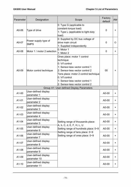
GK600 User Manual Chapter 5 List of Parameters
- 73 -
Parameter Designation Scope Factory default
Attr
A0-06 Type of drive
0: Type G (applicable to constant-torque load) 1: Type L (applicable to light-duty load)
0 ×
A0-07 Power supply type of SMPS
0: Supplied by DC bus voltage of drive main circuit 1: Supplied independently
0 ◎
A0-08 Motor 1 / motor 2 selection 0: Motor 1 1: Motor 2
0 ×
A0-09 Motor control technique
Ones place: motor 1 control technique 0: V/f control 1: Sensor-less vector control 1 2: Sensor-less vector control 2 Tens place: motor 2 control technique 0: V/f control 1: Sensor-less vector control 1 2: Sensor-less vector control 2
00 ×
Group A1: User-defined Display Parameters
A1-00 User-defined display parameter 1
Setting range of thousands place: A, b, C, d, E, F, H, L, U Setting range of hundreds place: 0~9 Setting range of tens place: 0~9 Setting range of ones place: 0~9
A0-00 ×
A1-01 User-defined display parameter 2
A0-00 ×
A1-02 User-defined display parameter 3
A0-00 ×
A1-03 User-defined display parameter 4
A0-00 ×
A1-04 User-defined display parameter 5
A0-00 ×
A1-05 User-defined display parameter 6
A0-00 ×
A1-06 User-defined display parameter 7
A0-00 ×
A1-07 User-defined display parameter 8
A0-00 ×
A1-08 User-defined display parameter 9
A0-00 ×
A1-09 User-defined display parameter 10
A0-00 ×
A1-10 User-defined display parameter 11
A0-00 ×

Chapter 5 List of Parameters GK600 User Manual
- 74 -
Parameter Designation Scope Factory default
Attr
A1-11 User-defined display parameter 12
A0-00 ×
A1-12 User-defined display parameter 13
A0-00 ×
A1-13 User-defined display parameter 14
A0-00 ×
A1-14 User-defined display parameter 15
A0-00 ×
A1-15 User-defined display parameter 16
A0-00 ×
A1-16 User-defined display parameter 17
A0-00 ×
A1-17 User-defined display parameter 18
A0-00 ×
A1-18 User-defined display parameter 19
A0-00 ×
A1-19 User-defined display parameter 20
A0-00 ×
A1-20 Parameter group display/hide setting 1
0~FFFF FFFF ×
A1-21 Parameter group display/hide setting 2
0~FFFF FFFF ×
Group b Run Parameter Setting Group b0 Frequency Setting
b0-00 FREQ set mode
0: Master FREQ set 1: Master & auxiliary computation result 2: Switch between master and auxiliary set 3: Switch between master FREQ set, and master & auxiliary computation result 4: Switch between auxiliary FREQ set, and master & auxiliary computation result
0 ×
b0-01 Master FREQ set
0: Digital setting (b0-02) + ∧ / ∨ adjustment on control panel 1: Digital setting (b0-02) + terminal
UP/DOWN adjustment 2: Analog input AI1 3: Analog input AI2 4: Analog input EAI (on IO option)
0 ×

GK600 User Manual Chapter 5 List of Parameters
- 75 -
Parameter Designation Scope Factory default
Attr
5: X6/DI pulse input 6: Process PID output 7: PLC 8: Multi-step speed 9: Communication
b0-02 Master FREQ digital setting Lower limit freq ~ upper limit freq 50.00Hz △
b0-03 Auxiliary FREQ set
0: No setting 1: Digital setting (b0-04) + ∧/∨
adjustment on control panel 2: Digital setting (b0-04) + terminal
UP/DOWN adjustment 3: Analog input AI1 4: Analog input AI2 5: Analog input EAI (on IO option
board) 6: X6/DI pulse input 7: Process PID output 8: PLC 9: Multi-step speed 10: Communication
0 ×
b0-04 Auxiliary FREQ digital setting
Lower limit FREQ ~ upper limit FREQ 0.00Hz △
b0-05 Auxiliary FREQ range 0: Relative to maximum FREQ 1: Relative to master FREQ
0 ×
b0-06 Auxiliary FREQ coeff 0.0%~100.0% 100.0% ×
b0-07 Computation of master and auxiliary FREQ
0: Master + auxiliary 1: Master - auxiliary 2: Max {master, auxiliary} 3: Min {master, auxiliary}
0 ×
b0-08 Maximum FREQ Upper limit FREQ ~600.00Hz 50.00Hz × b0-09 Upper limit FREQ Lower limit FREQ ~ maximum FREQ 50.00Hz × b0-10 Lower limit FREQ 0.00Hz~upper limit FREQ 0.00Hz ×
b0-11 Operation when set FREQ lower than lower limit FREQ
0: Run at lower limit FREQ 1: Run at 0 Hz 2: Stop
0 ×
b0-12 Time-delay of stop when set FREQ lower than lower limit FREQ
0.0s ~ 6553.5s 0.0s ×
b0-13 Lower limit of skip FREQ band 1
0.00Hz~upper limit FREQ 0.00Hz ×
b0-14 Upper limit of skip FREQ band 1
0.00Hz~upper limit FREQ 0.00Hz ×

Chapter 5 List of Parameters GK600 User Manual
- 76 -
Parameter Designation Scope Factory default
Attr
b0-15 Lower limit of skip FREQ band 2
0.00Hz~upper limit FREQ 0.00Hz ×
b0-16 Upper limit of skip FREQ band 2
0.00Hz~upper limit FREQ 0.00Hz ×
b0-17 Lower limit of skip FREQ band 3
0.00Hz~upper limit FREQ 0.00Hz ×
b0-18 Upper limit of skip FREQ band 3
0.00Hz~upper limit FREQ 0.00Hz ×
b0-19 Jog FREQ 0.00Hz~upper limit FREQ 5.00Hz △
Group b1 Start/Stop Control
b1-00 Run command 0: Control panel control 1: Terminal control 2: Communication control
0 ×
b1-01 Binding of run command and frequency set
Ones place: frequency set bundled under control panel control: 0: No binding 1: Digital setting (b0-02) + ∧/∨ adjustment on control panel 2: Digital setting (b0-02) + terminal UP/DOWN adjustment 3: Analog input AI1 4: Analog input AI2 5: Analog input EAI (on IO option board) 6: X6/DI pulse input 7: Process PID output 8: Simple PLC 9: Multi-step FREQ A: Communication input Tens place: FREQ set bundled under terminal control (same as ones place) Hundreds place: FREQ set bundled under communication control (same as ones place)
000 ×
b1-02 Run direction 0: Forward 1: Reverse
0 △
b1-03 Reverse disabled 0: Reverse enabled 1: Reverse disabled
0 ×
b1-04 Dead time between forward and reverse
0.0s~3600.0s 0.0s △

GK600 User Manual Chapter 5 List of Parameters
- 77 -
Parameter Designation Scope Factory default
Attr
b1-05 Start method
0: From start FREQ 1: DC braking start 2: Flying start 1 3: Flying start 2
0 ×
b1-06 Start FREQ 0.00Hz~upper limit FREQ 0.00Hz × b1-07 Holding time of start FREQ 0.0s~3600.0s 0.0s △ b1-08 DC braking current at start 0.0%~200.0% 0.0% △ b1-09 DC braking time at start 0.00s~30.00s 0.00s △ b1-10 Flying start 1 current 0.0~200.0% 100.0% × b1-11 Flying start 1 Decel time 0.1s~20.0s 2.0s ×
b1-12 Flying start 1 adjustment coeff
0.0~100.0% 1.0% ×
b1-13 Stop method 0: Ramp to stop 1: Coast to stop 2: Ramp to stop + DC brake
0 ×
b1-14 Start FREQ of DC brake stop
0.00Hz~upper limit FREQ 0.00Hz ×
b1-15 DC brake current 0.0%~200.0% 0.0% △ b1-16 DC brake time 0.00s~30.00s 0.00s △
b1-17 Overexcitation brake 0: Disabled 1: Enabled 1 ×
b1-18 Dynamic brake 0: Disabled 1: Enabled
0 ×
b1-19 Dynamic brake threshold voltage 650V~750V 720V ×
b1-20 Auto restart when power up again after power loss
0: Disabled 1: Enabled
0 ×
b1-21 Time delay of auto restart when power up again 0.0s~10.0s 0.0s △
Group b2 Accel/Decel Parameters
b2-00
Accel/Decel time resolution
0:0.01s 1:0.1s 2:1s
1 ×
b2-01 Accel time 1 0s~600.00s/6000.0s/60000s 6.0s △ b2-02 Decel time 1 0s~600.00s/6000.0s/60000s 6.0s △ b2-03 Accel time 2 0s~600.00s/6000.0s/60000s 6.0s △ b2-04 Decel time 2 0s~600.00s/6000.0s/60000s 6.0s △ b2-05 Accel time 3 0s~600.00s/6000.0s/60000s 6.0s △ b2-06 Decel time 3 0s~600.00s/6000.0s/60000s 6.0s △ b2-07 Accel time 4 0s~600.00s/6000.0s/60000s 6.0s △

Chapter 5 List of Parameters GK600 User Manual
- 78 -
Parameter Designation Scope Factory default
Attr
b2-08 Decel time 4 0s~600.00s/6000.0s/60000s 6.0s △
b2-09 Decel time for emergency stop
0s~600.00s/6000.0s/60000s 6.0s △
b2-10 Jog Accel time 0s~600.00s/6000.0s/60000s 6.0s △
b2-11 Jog Decel time 0s~600.00s/6000.0s/60000s 6.0s △
b2-12 Accel/Decel curve
0: Linear Accel/Decel 1: Broken-line Accel/Decel 2: S-curve Accel/Decel A 3: S-curve Accel/Decel B 4: S-curve Accel/Decel C
0 ×
b2-13 Accel time switching FREQ of broken-line Accel/Decel
0.00Hz~upper limit FREQ 0.00Hz △
b2-14 Decel time switching FREQ of broken-line Accel/Decel
0.00Hz~upper limit FREQ 0.00Hz △
b2-15 Time of Accel S-curve first segment
0.00s~60.00s (S-curve A) 0.20s △
b2-16 Time of Accel S-curve last segment
0.00s~60.00s (S-curve A) 0.20s △
b2-17 Time of Decel S-curve first segment
0.00s~60.00s (S-curve A) 0.20s △
b2-18 Time of Decel S-curve last segment
0.00s~60.00s (S-curve A) 0.20s △
b2-19 Proportion of Accel S-curve first segment
0.0%~100.0% (S-curve B) 20.0% △
b2-20 Proportion of Accel S-curve last segment
0.0%~100.0% (S-curve B) 20.0% △
b2-21 Proportion of Decel S-curve first segment
0.0%~100.0% (S-curve B) 20.0% △
b2-22 Proportion of Decel S-curve last segment
0.0%~100.0% (S-curve B) 20.0% △
Group C Input and Output Terminals Group C0 Digital Input
C0-00 Enabled condition of run command terminals when power up
0: Trigger edge detected + ON detected 1: ON detected
0 ×
C0-01 Function of terminal X1 0: No function 1: JOG forward 2: JOG reverse 3: Run forward (FWD) 4: Run reverse (REV) 5: Three-wire control
3 ×
C0-02 Function of terminal X2 4 ×
C0-03 Function of terminal X3 1 ×

GK600 User Manual Chapter 5 List of Parameters
- 79 -
Parameter Designation Scope Factory default
Attr
C0-04 Function of terminal X4 6: Run suspended 7: External stop 8: Emergency stop 9: Stop command + DC brake 10: DC brake stop 11: Coast to stop 12: Terminal UP 13: Terminal DOWN 14: Clear UP/DOWN (including ∧/∨ key) adjustment 15: Multi-step FREQ terminal 1 16: Multi-step FREQ terminal 2 17: Multi-step FREQ terminal 3 18: Multi-step FREQ terminal 4 19: Accel/Decel time determinant 1 20: Accel/Decel time determinant 2 21: Accel/Decel disabled(ramp stop not inclusive) 22: External fault input 23: Fault reset (RESET) 24: Pulse input (valid only for X6/DI) 25: Motor 1/2 switchover 26: Reserved 27: Run command switched to control panel control 28: Run command switched to terminal control 29: Run command switched to communication control 30: Frequency set mode shift 31: Master FREQ set switched to digital setting b0-02 32: Auxiliary FREQ set switched to digital setting b0-04 33: PID adjustment direction 34: PID paused 35: PID integration paused 36: PID parameter switch 37: Count input 38: Count clear 39: Length count 40: Length clear
23 ×
C0-05 Function of terminal X5 11 ×
C0-06 Function of terminal X6/DI 0 ×
C0-07 Function of terminal EX (on IO option board)
0 ×
C0-08 Function of terminal AI1 (Digital enabled)
0 ×
C0-09 Function of terminal AI2 (Digital enabled)
0 ×
C0-10 Function of terminal EAI (Digital enabled) (on IO option board)
0 ×

Chapter 5 List of Parameters GK600 User Manual
- 80 -
Parameter Designation Scope Factory default
Attr
41~62: Reserved 63: Simple PLC paused 64: Simple PLC disabled 65: Simple PLC stop memory clear 66: Start wobble frequency 67: Clear wobble frequency status 68: Run prohibited 69: DC brake in run 70: Analog input curve switching 71~99: Reserved
C0-11 Filtering time of digital input terminal
0.000s~1.000s 0.010s △
C0-12 Delay time of terminal X1 0.0s~3600.0s 0.0s △ C0-13 Delay time of terminal X2 0.0s~3600.0s 0.0s △
C0-14 Digital input terminal enabled status setting 1
Ones place: X1 0: Positive logic 1: Negative logic Tens place: X2 (same as ones place) Hundreds place: X3 (same as ones place) Thousands place: X4 (same as ones place)
0000 ×
C0-15 Digital input terminal enabled status setting 2
Ones place: X5 0: Positive logic 1: Negative logic Tens place: X6 (valid as ordinary terminal, same as ones place) Hundreds place: (on IO option board, same as ones place) Thousands place: reserved
0000 ×
C0-16 Digital input terminal enabled status setting 3
Ones place: AI1 0: Positive logic 1: Negative logic Tens place: AI2 (same as ones place) Hundreds place: EAI (on IO option board, same as ones place) Thousands place: reserved
0000 ×
C0-17 Terminal UP/DOWN FREQ adjustment action
Ones place: at stop 0: Cleared 1: Maintained Tens place: on power loss 0: Cleared
0000 △
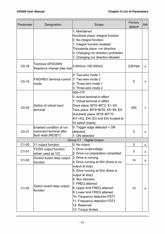
GK600 User Manual Chapter 5 List of Parameters
- 81 -
Parameter Designation Scope Factory default
Attr
1: Maintained Hundreds place: integral function 0: No integral function 1: Integral function enabled Thousands place: run direction 0: Changing run direction prohibited 1: Changing run direction allowed
C0-18 Terminal UP/DOWN frequency change step size 0.00Hz/s~100.00Hz/s
0.03 Hz/s △
C0-19 FWD/REV terminal control mode
0: Two-wire mode 1 1: Two-wire mode 2 2: Three-wire mode 1 3: Three-wire mode 2
0 ×
C0-20 Option of virtual input terminal
000~77F 0: Actual terminal in effect 1: Virtual terminal in effect Ones place: BIT0~BIT3: X1~X4 Tens place: BIT4~BIT6: X5~X6, EX Hundreds place: BIT8~BIT10: AI1~AI2, EAI (EX and EAI located at IO option board)
000 ×
C0-21 Enabled condition of run command terminal after fault reset (RESET)
0: Trigger edge detected + ON detected 1: ON detected
0 △
Group C1 Digital Output C1-00 Y1 output function 0: No output
1: Drive undervoltage 2: Drive run preparation completed 3: Drive is running 4: Drive running at 0Hz (there is no output at stop) 5: Drive running at 0Hz (there is output at stop) 6: Run direction 7: FREQ attained 8: Upper limit FREQ attained 9: Lower limit FREQ attained 10: Frequency detection FDT1 11: Frequency detection FDT2 12: Reserved 13: Torque limited
0 △
C1-01 Y2/DO output function (when used as Y2)
0 △
C1-02 Control board relay output function
14 △
C1-03 Option board relay output function
15 △

Chapter 5 List of Parameters GK600 User Manual
- 82 -
Parameter Designation Scope Factory default
Attr
14: Fault output 15: Alarm output 16: Drive (motor) overloaded alarm 17: Drive overheat alarm 18: Zero current detection 19: X1 20: X2 21: Motor 1/ 2 indication 22: Set count value attained 23: Designated count value attained 24: Length attained 25: Consecutive run time attained 26: Accumulative run time attained 27: Brake control 28: Reserved 29: Reserved 30: PLC step completed 31: PLC cycle completed 32: Wobble frequency attains to upper or lower limit frequency 33: Upper/lower limit of set FREQ attained 34: Target FREQ attained (set by C2-29) 35~99: Reserved
C1-04 Y1 output time delay 0.0s~3600.0s 0.0s △ C1-05 Y2 output time delay 0.0s~3600.0s 0.0s △
C1-06 Control board relay output time delay
0.0s~3600.0s 0.0s △
C1-07 Option board relay output time delay
0.0s~3600.0s 0.0s △
C1-08 Enabled state of digital output
Ones place: Y1 0: Positive logic 1: Negative logic Tens place: Y2 (same as ones place) Hundreds place: control board relay output (same as ones place) Thousands place: option board relay output (same as ones place)
0000 ×
C1-09 Detected object of FREQ detection (FDT)
Ones place: FDT1 detected object 0: Speed set value (FREQ after Accel/Decel)
00 △

GK600 User Manual Chapter 5 List of Parameters
- 83 -
Parameter Designation Scope Factory default
Attr
1: Detected speed value Tens place: FDT2 detected object 0: Speed set value (FREQ after Accel/Decel) 1: Detected speed value
C1-10 FDT1 upper value 0.00Hz~maximum FREQ 50.00Hz △ C1-11 FDT1 lower value 0.00Hz~maximum FREQ 49.00Hz △ C1-12 FDT2 upper value 0.00Hz~maximum FREQ 25.00Hz △ C1-13 FDT2 lower value 0.00Hz~maximum FREQ 24.00Hz △
C1-14 Detection width of FREQ attained
0.00Hz~maximum FREQ 2.50Hz △
C1-15 Zero current detection value
0.0%~50.0% 5.0% △
C1-16 Zero current detection time 0.01s~50.00s 0.50s △
Group C2 Analog and Pulse Input
C2-00 Analog input curve
Ones place: AI1 input curve 0: Curve 1 (2 points) 1: Curve 2 (4 points) 2: Curve 3 (4 points) 3: Curve 2 and curve 3 switchover Tens place: AI2 input curve (same as ones place) Hundreds place: EAI input curve (same as ones place) Thousands place: reserved
0210 ×
C2-01 Curve 1 maximum input Curve 1 minimum input ~ 110.0% 100.0% △
C2-02 Corresponding set value of curve 1 maximum input
-100.0%~100.0% 100.0% △
C2-03 Curve 1 minimum input -110.0% ~ curve 1 maximum input 0.0% △
C2-04 Corresponding set value of curve 1 minimum input
-100.0%~100.0% 0.0% △
C2-05 Curve 2 maximum input Range: input of curve 2 inflection point A~110.0%
100.0% △
C2-06 Set value corresponding to curve 2 maximum input Range: -100.0%~100.0% 100.0% △
C2-07 Input of curve 2 inflection
point A Input of curve 2 inflection point B ~ curve 2 maximum input
0.0% △
C2-08 Set value Cor. to input of
curve 2 inflection point A Range: -100.0%~100.0% 0.0% △

Chapter 5 List of Parameters GK600 User Manual
- 84 -
Parameter Designation Scope Factory default
Attr
C2-09 Input of curve 2 inflection point B
Range: Curve 2 minimum input ~ Input of curve 2 inflection point A
0.0% △
C2-10 Set value corresponding to input of curve 2 inflection point B
Range: -100.0%~100.0% 0.0%
△
C2-11 Curve 2 minimum input Range: -110.0%~ input of curve 2 inflection point B
0.0% △
C2-12 Set value corresponding to curve 2 minimum input
Range: -100.0%~100.0% 0.0% △
C2-13 Curve 3 maximum input Range: input of curve 3 inflection point A ~110.0%
100.0% △
C2-14 Set value corresponding to curve 3 maximum input
Range: -100.0%~100.0% 100.0% △
C2-15 Input of curve 3 inflection point A
Range: input of curve 3 inflection point B ~ curve 3 maximum input
0.0% △
C2-16 Set value corresponding to input of curve 3 inflection point A
Range: -100.0%~100.0% 0.0% △
C2-17 Input of curve 3 inflection point B
Range: curve 3 minimum input~ input of curve 3 inflection point A
0.0% △
C2-18 Set value corresponding to input of curve 3 inflection point B
Range: -100.0%~100.0% 0.0% △
C2-19 Curve 3 minimum input Range: -110.0%~ input of curve 3 inflection point B
0.0% △
C2-20 Set value corresponding to curve 3 minimum input
Range: -100.0%~100.0% 0.0% △
C2-21 AI1 terminal filtering time 0.000s~10.000s 0.1s △ C2-22 AI2 terminal filtering time 0.000s~10.000s 0.1s △
C2-23 EAI terminal filtering time (on IO option board)
0.000s~10.000s 0.1s △
C2-24 DI maximum input Range: C2-26~50.0kHz 50.0kHz △
C2-25 Set value corresponding to DI maximum input
Range: -100.0%~100.0% 100.0% △
C2-26 DI minimum input Range: 0.0kHz~C2-24 0.0kHz △
C2-27 Set value corresponding to DI minimum input
Range: -100.0%~100.0% 0.0% △
C2-28 DI filtering time 0.000s~1.000s 0.001s △

GK600 User Manual Chapter 5 List of Parameters
- 85 -
Parameter Designation Scope Factory default
Attr
C2-29 Target FREQ 0.00Hz~upper limit FREQ (enabled when C1-00 ~C1-03 is set to 34 )
0.00Hz △
Group C3 Analog and Pulse Output C3-00 AO1 output function 0: No output
1: Set FREQ 2: Output FREQ 3: Output current (to drive rated) 4: Output torque (absolute value) 5: Output voltage 6: Output power 7: Bus voltage 8: Reserved 9: Torque current 10: Magnetic flux current 11:AI1 12:AI2 13:EAI 14: Reserved 15:DI 16:Communication input percentage 17: Output FREQ before compensation 18:Output current (relative to motor rated current) 19:Output torque (direction hinted) 20:Set torque (direction hinted) 21~99: Reserved
2 △
C3-01 EAO output function (on IO option)
1 △
C3-02 Y2/DO output function (when used as DO)
0 △
C3-03 AO1 offset -100.0%~100.0% 0.0% × C3-04 AO1 gain -2.000~2.000 1.000 × C3-05 AO1 filtering time 0.0s~10.0s 0.0s △ C3-06 EAO offset -100.0%~100.0% 0.0% × C3-07 EAO gain -2.000~2.000 1.000 × C3-08 EAO filtering time 0.0s~10.0s 0.0s △
C3-09 DO maximum output pulse FREQ
0.1kHz~50.0kHz 50.0kHz △

Chapter 5 List of Parameters GK600 User Manual
- 86 -
Parameter Designation Scope Factory default
Attr
C3-10 DO output center point
0: No center point 1: Center point is (C3-09)/2, and the corresponding parameter value is positive when FREQ is higher than center point 2: Center point is (C3-09)/2, and the corresponding parameter value is positive when FREQ is lower than center point
0 ×
C3-11 DO output filtering time 0.00s~10.00s 0.00s △
Group C4 Automatic Correction of Analog Input
C4-00 Analog correction
0: No correction 1:Correct AI1 2:Correct AI2 3:Correct EAI
0 ×
C4-01 Sampling value of AI1 calibration point 1
Range: 0.00V~10.00V 1.00V ◎
C4-02 Input value of AI1 calibration point 1
Range: 0.00V~10.00V 1.00V ×
C4-03 Sampling value of AI1 calibration point 2
Range: 0.00V~10.00V 9.00V ◎
C4-04 Input value of AI1 calibration point 2
Range: 0.00V~10.00V 9.00V ×
C4-05 Sampling value of AI2 calibration point 1
Range: -10.00V~10.00V 1.00V ◎
C4-06 Input value of AI2 calibration point 1
Range: -10.00V~10.00V 1.00V ×
C4-07 Sampling value of AI2 calibration point 2
Range: -10.00V~10.00V 9.00V ◎
C4-08 Input value of AI2 calibration point 2
Range: -10.00V~10.00V 9.00V ×
C4-09 Sampling value of EAI calibration point 1
Range: 0.00V~10.00V 1.00V ◎
C4-10 Input value of EAI calibration point 1
Range: 0.00V~10.00V 1.00V ×
C4-11 Sampling value of EAI calibration point 2
Range: 0.00V~10.00V 9.00V ◎
C4-12 Input value of EAI calibration point 2
Range: 0.00V~10.00V 9.00V ×

GK600 User Manual Chapter 5 List of Parameters
- 87 -
Parameter Designation Scope Factory default
Attr
Group d Motor and Control Parameters Group d0 Parameters of Motor 1
d0-00 Type of motor 1 0: Ordinary motor 1: Variable frequency motor 1 ×
d0-01 Power rating of motor 1 0.4kW~6553.5kW Model
dependent ×
d0-02 Rated voltage of motor 1 0V~480V (for drives 400V level) 380V ×
d0-03 Rated current of motor 1 0.0A~6553.5A Model dependent
×
d0-04 Rated frequency of motor 1 0.00Hz~upper limit frequency 50.00Hz × d0-05 Pole number of motor 1 1~80 4 ×
d0-06 Rated speed of motor 1 0~65535r/min Model
dependent ×
d0-07 Stator resistance R1 of motor 1
0.001Ω~65.535Ω Model
dependent ×
d0-08 Leakage inductance L1 of motor 1
0.1mH~6553.5mH Model
dependent ×
d0-09 Rotor resistance R2 of motor 1
0.001Ω~65.535Ω Model
dependent ×
d0-10 Mutual inductance L2 of motor 1
0.1mH~6553.5mH Model
dependent ×
d0-11 No-load current of motor 1 0.0A~6553.5A Model
dependent ×
d0-12 Flux weakening coeff 1 of motor 1
0.0000~1.0000 Model
dependent ×
d0-13 Flux weakening coeff 2 of motor 1
0.0000~1.0000 Model
dependent ×
d0-14 Flux weakening coeff 3 of motor 1
0.0000~1.0000 Model
dependent ×
d0-15 Reserved Reserved Reserved × d0-16 Reserved Reserved Reserved × d0-17 Reserved Reserved Reserved × d0-18 Reserved Reserved Reserved × d0-19 Reserved Reserved Reserved × d0-20 Reserved Reserved Reserved × d0-21 Reserved Reserved Reserved ×
d0-22 Autotuning of motor 1 0: No autotuning 1: Static autotuning 2: Rotary autotuning
0 ×

Chapter 5 List of Parameters GK600 User Manual
- 88 -
Parameter Designation Scope Factory default
Attr
d0-23 Overload protection of motor 1
0: No protection 1: Judged by motor current 2: Judged by temperature transducer
1 ×
d0-24 Overload protection detection time of motor 1
0.1min~15.0min 5.0min ×
d0-25 Temperature transducer signal input of motor 1
0: AI1 1: AI2 2: EAI (on IO board)
1 ×
d0-26 Thermal protection threshold of motor 1 temperature transducer
0.00V~10.00V 10.00V ×
Group d1 V/f Control Parameters of Motor 1
d1-00 V/f curve setting
0: Linear V/f 1: Multi-stage V/f (d1-01~d1-08) 2: 1.2nd power 3: 1.4th power 4: 1.6th power 5: 1.8th power 6: 2.0nd power 7: V/f separated mode 1 8: V/f separated mode 2
0 ×
d1-01 V/f FREQ value f3 0.00Hz~motor rated FREQ 50.00Hz × d1-02 V/f voltage value V3 0.0%~100.0% 100.0% × d1-03 V/f FREQ value f2 d1-05~d1-01 0.00Hz × d1-04 V/f voltage value V2 0.0%~100.0% 0.0% × d1-05 V/f FREQ value f1 d1-07~d1-03 0.00Hz × d1-06 V/f voltage value V1 0.0%~100.0% 0.0% × d1-07 V/f FREQ value f0 0.00Hz~d1-05 0.00Hz × d1-08 V/f voltage value V0 0.0%~100.0% 0.0% × d1-09 Torque boost 0.0%~30.0% 0.0% △ d1-10 Slip compensation gain 0.0%~400.0% 100.0% △ d1-11 Droop control 0.00Hz~maximum FREQ 0.00Hz △
d1-12 Current limitation mode
0: Disabled 1: Set by d1-13 2: Set by AI1 3: Set by AI2 4: Set by EAI 5: Set by X6/DI
1 ×
d1-13 Digital setting of current limit value
20.0%~200.0% 160.0% ×

GK600 User Manual Chapter 5 List of Parameters
- 89 -
Parameter Designation Scope Factory default
Attr
d1-14 Current limit coeff on flux weakening
0.001~1.000 0.500 △
d1-15 Energy saving percentage 0%~40.0% 0.0% △
d1-16 V/f oscillation suppression gain 1
0~3000 38 △
d1-17 V/f oscillation suppression gain 2
0~3000 0 △
d1-18 Voltage setting on V/f separated pattern
0: d1-19 digital setting 1: Set by AI1 2: Set by AI2 3: Set by EAI 4: Process PID output 5: AI1 + process PID output
0 ×
d1-19 Digital set voltage on V/f separated pattern
0.0%~100.0% 0.0% △
d1-20 Voltage variation time on V/f separated pattern
0.00s~600.00s 0.01s △
Group d2 Vector Control Parameters of Motor 1 d2-00 Reserved Reserved 0 ×
d2-01 ASR high-speed proportional gain Kp1
0.0~20.0 2.0 △
d2-02 ASR high-speed integration time Ti1 0.000s~8.000s 0.200 △
d2-03 ASR low-speed proportional gain Kp2
0.0~20.0 2.0 △
d2-04 ASR low-speed integration time Ti2
0.000s~8.000s 0.200 △
d2-05 ASR switching FREQ 1 0.00Hz~d2-06 5.00Hz △ d2-06 ASR switching FREQ 2 d2-05~upper limit FREQ 10.00Hz △ d2-07 ASR input filtering time 0.0ms~500.0ms 0.3ms △ d2-08 ASR output filtering time 0.0ms~500.0ms 0.3ms △ d2-09 ACR proportion coeff Kp 0.000~4.000 1.000 △ d2-10 ACR integration coeff Ki 0.000~4.000 1.000 △ d2-11 Pre-excitation time 0.000s~5.000s 0.200s △
d2-12 Driven torque restriction source
0: d2-14 digital setting 1: AI1 2: AI2 3: EAI (on IO option board) 4: X6/DI pulse input 5: Communication
0 ×

Chapter 5 List of Parameters GK600 User Manual
- 90 -
Parameter Designation Scope Factory default
Attr
d2-13 Braking torque restriction source
0: d2-15 digital setting 1: AI1 2: AI2 3: EAI (on IO option board) 4: X6/DI pulse input 5: Communication
0 ×
d2-14 Digital setting of driven torque
0.0%~200.0% 180.0% △
d2-15 Digital setting of braking torque 0.0%~200.0% 180.0% △
d2-16 Torque limit coefficient in flux weakening
0.0%~100.0% 50.0% △
d2-17 Driven slip compensation gain 10.0%~300.0% 100.0% △
d2-18 Brake slip compensation gain
10.0%~300.0% 100.0% △
Group d3 Parameters of Motor 2
d3-00 Type of motor 2 0: Ordinary motor 1: Variable-frequency motor
0 ×
d3-01 Power rating of motor 2 0.4kW~6553.5kW Model
dependent ×
d3-02 Rated voltage of motor 2 0V~480V (for drives 400V level) 380V ×
d3-03 Rated current of motor 2 0.0A~6553.5A Model
dependent ×
d3-04 Rated frequency of motor 2 0.00Hz~upper limit frequency 50.00Hz ×
d3-05 Pole number of motor 2 1~80 4 ×
d3-06 Rated speed of motor 2 0~65535r/min Model
dependent ×
d3-07 Stator resistance R1 of motor 2
0.001Ω~65.535Ω Model
dependent ×
d3-08 Leakage inductance L1 of motor 2
0.1mH~6553.5mH Model
dependent ×
d3-09 Rotor resistance R2 of motor 2
0.001Ω~65.535Ω Model
dependent ×
d3-10 Mutual inductance L2 of motor 2
0.1mH~6553.5mH Model
dependent ×
d3-11 No-load current of motor 2 0.0A~6553.5A Model
dependent ×
d3-12 Flux weakening coeff 1 of motor 2 0.0000~1.0000
Model dependent ×

GK600 User Manual Chapter 5 List of Parameters
- 91 -
Parameter Designation Scope Factory default
Attr
d3-13 Flux weakening coeff 2 of motor 2
0.0000~1.0000 Model
dependent ×
d3-14 Flux weakening coeff 3 of motor 2
0.0000~1.0000 Model
dependent ×
d3-15 Reserved Reserved Reserved × d3-16 Reserved Reserved Reserved × d3-17 Reserved Reserved Reserved × d3-18 Reserved Reserved Reserved × d3-19 Reserved Reserved Reserved × d3-20 Reserved Reserved Reserved × d3-21 Reserved Reserved Reserved ×
d3-22 Autotuning of motor 2 0: No autotuning 1: Static autotuning 2: Rotary autotuning
0 ×
d3-23 Overload protection mode of motor 2
0: No action 1: Judged by motor current 2: Judged by temperature transducer
1 ×
d3-24 Overload protection detection time of motor 2
0.1min~15.0min 5.0min ×
d3-25 Input channel of motor 2 temperature transducer signal
0: AI1 1: AI2 2: EAI (on IO option)
0 ×
d3-26 Thermal protection threshold of motor 2 temperature transducer
0.00V~10.00V 10.00V ×
Group d4 V/f Control Parameter of Motor 2
d4-00 V/f curve setting
0: Linear V/f 1: Various segments V/f (d4-01~d4-08) 2: 1.2nd power 3: 1.4th power 4: 1.6th power 5: 1.8th power 6: 2.0nd power 7: V/f separated mode 1 8: V/f separated mode 2
0 ×
d4-01 V/f FREQ value f3 0.00Hz~rated FREQ of motor 50.00Hz × d4-02 V/f voltage value V3 0.0%~100.0% 100.0% × d4-03 V/f FREQ value f2 d4-05~d4-01 0.00Hz × d4-04 V/f voltage value V2 0.0%~100.0% 0.0% ×

Chapter 5 List of Parameters GK600 User Manual
- 92 -
Parameter Designation Scope Factory default
Attr
d4-05 V/f FREQ value f1 d4-07~d4-03 0.00Hz × d4-06 V/f voltage value V1 0.0%~100.0% 0.0% × d4-07 V/f FREQ value f0 0.00Hz~d4-05 0.00Hz × d4-08 V/f voltage value V0 0.0%~100.0% 0.0% × d4-09 Torque boost 0.0%~30.0% 0.0% △ d4-10 Slip compensation gain 0.0%~300.0% 100.0% △
d4-11 Drooping FREQ of droop control
0.00Hz~maximum frequency 0.00Hz △
d4-12 Current limitation source
0: Disabled 1: Set by d4-13 2: Set by AI1 3: Set by AI2 4: Set by EAI 5: Set by X6/DI
1 ×
d4-13 Digital setting of current limit value 20.0%~200.0% 160.0% ×
d4-14 Flux weakening current limit coeff
0.001~1.000 0.500 △
d4-15 Energy saving percentage 0.0%~40.0% 0.0% △
d4-16 V/f oscillation suppression gain 1
0~3000 38 △
d4-17 V/f oscillation suppression gain 2
0~3000 0 △
d4-18 Voltage setting on V/f separated pattern
0: d1-19 digital setting 1: Set by AI1 2: Set by AI2 3: Set by EAI 4: Process PID output 5: AI1 + process PID output
0 △
d4-19 Digital voltage setting on V/f separation pattern 0.0%~100.0% 0.0%
△
d4-20 Voltage variation time on V/f separated pattern
0.00s~600.00s 0.01s △
Group d5 Vector Control Parameters of Motor 2 d5-00 Reserved Reserved Reserve ×
d5-01 ASR Hi-speed proportional gain Kp1
0.0~20.0 2.0 △
d5-02 ASR Hi-speed integration time Ti1
0.000s~8.000s 0.200 △
d5-03 ASR low-speed proportional gain Kp2
0.0~20.0 2.0 △

GK600 User Manual Chapter 5 List of Parameters
- 93 -
Parameter Designation Scope Factory default
Attr
d5-04 ASR low-speed integration time Ti2
0.000s~8.000s 0.200 △
d5-05 ASR switching FREQ 1 0.00Hz~d5-06 5.00Hz △ d5-06 ASR switching FREQ 2 D5-05~upper limit FREQ 10.00Hz △ d5-07 ASR input filtering time 0.0ms~500.0ms 0.3ms △ d5-08 ASR output filtering time 0.0ms~500.0ms 0.3ms △ d5-09
ACR proportion coefficient Kp
0.000~4.000 1.000 △
d5-10 ACR integration coeff Ki 0.000~4.000 1.000 △ d5-11 Pre-excitation time 0.000s~5.000s 0.200s △
d5-12 Driven torque restriction source
0: d5-14 digital setting 1: AI1 2: AI2 3: EAI (on IO option) 4: X6/DI pulse input 5: Communication
0 ×
d5-13 Braking torque restriction source
0: d5-15 digital setting 1: AI1 2: AI2 3: EAI (on IO option) 4: X6/DI pulse input 5: Communication
0 ×
d5-14 Digital setting of driven torque limit value
0.0%~200.0% 180.0% △
d5-15 Digital setting of braking torque limit value
0.0%~200.0% 180.0% △
d5-16 Flux weakening torque limit coeff
0.0%~100.0% 50.0% △
d5-17 Driven slip compensation gain
10.0%~300.0% 100.0% △
d5-18 Brake slip compensation gain
10.0%~300.0% 100.0% △
Group E Enhanced Function and Protection Parameters Group E0 Enhanced Function
E0-00 Switching FREQ
≤15kW: 0.7kHz~16.0kHz, factory default: 8.0 kHz 18.5kW~45kW: 0.7kHz~10.0kHz, factory default: 4.0 kHz 55kW~75kW:
Model dependent △

Chapter 5 List of Parameters GK600 User Manual
- 94 -
Parameter Designation Scope Factory default
Attr
0.7kHz~16.0kHz, factory default: 3.0 kHz ≥90kW: 0.7kHz~3.0kHz, factory default: 2.0 kHz
E0-01 PWM optimization
Ones place: switching FREQ relation with temperature 0: Self-adaption 1: No adaption Tens place: PWM modulation mode 0: Five-segment and seven-segment self-switchover 1: Five-segment mode 2: Seven-segment mode Hundreds place: over-modulation adaption 0: Disabled 1: Enabled Thousands place: PWM switching FREQ relation with output frequency 0: Self-adaption 1: No adaption
0100 ×
E0-02 Action when run time attained
Ones place: action when consecutive run time attained: 0: Run continued 1: Stop and fault reported Tens place: action when accumulative run time attained: 0: Run continued 1: Stop and fault reported Hundreds place: unit of run time 0: Second 1: Hour
000 ×
E0-03 Consecutive run time setting
0.0s(h)~6000.0s(h) 0.0 s(h) ×
E0-04 Accumulative run time setting
0.0s(h)~6000.0s(h) 0.0 s(h) ×
E0-05 Mechanical brake control 0: Disabled 1: Enabled
0 ×
E0-06 Mechanical brake open frequency
0.00Hz~10.00Hz 2.50Hz ×

GK600 User Manual Chapter 5 List of Parameters
- 95 -
Parameter Designation Scope Factory default
Attr
E0-07 Mechanical brake open current
0.0%~200.0% 120.0% ×
E0-08 Accel delay time after brake open
0.0s~10.0s 1.0s ×
E0-09 Mechanical brake FREQ 0.00Hz~10.00Hz 2.00Hz ×
E0-10 Mechanical brake close waiting time
0.0s~10.0s 0.0s ×
E0-11 Mechanical brake close holding time
0.0s~10.0s 1.0s ×
Group E1 Protection Parameters
E1-00 Overvoltage stall 0: Prohibited 1: Allowed 1 ×
E1-01 Overvoltage stall protection voltage
120%~150% 130% ×
E1-02 Undervoltage stall 0: Disabled 1: Enabled 0 ×
E1-03 Overload alarm
Ones place: detection option: 0: Always detect 1: Detect at constant speed only Tens place: compared with: 0: Motor rated current 1: Drive rated current Hundreds place: drive action 0: Alarm but run continued 1: Alarm and coast to stop
000 ×
E1-04 Overload alarm threshold 20.0%~200.0% 130.0% △
E1-05 Overload alarm activation time
0.1s~60.0s 5.0s △
E1-06 Protection action 1
Ones place: reserved Tens place: action at IGBT temperature measurement circuit fault (OH3): 0: Coast to stop 1: Alarm but run continued Hundreds place: abnormal EEPROM (EPr) : 0: Coast to stop 1: Alarm but run continued Thousands place: abnormal terminal communication (TrC): 0: Coast to stop 1: Alarm but run continued
0000 ×

Chapter 5 List of Parameters GK600 User Manual
- 96 -
Parameter Designation Scope Factory default
Attr
E1-07 Protection action 2
Ones place: abnormal power supply when running (SUE): 0: Coast to stop 1: Alarm but run continued Tens place: current detection circuit failed (CtC) 0: Coast to stop 1: Alarm but run continued Hundreds place: abnormal contactor (CCL): 0: Coast to stop 1: Alarm but run continued Thousands place: input supply fault /output phase loss (ISF, oPL): 0: Protection for neither input supply fault nor output phase loss 1: No protection for input supply fault, protection enabled for output phase loss 2: Protection enabled for input supply fault, no protection for output phase loss 3: Protection enabled both for input supply fault and output phase loss
3001 ×
E1-08 Fault memory after power loss
0: Not memorized after power loss 1: Memorized after power loss
0 ×
E1-09 Fault auto-reset times 0~20 0 × E1-10 Auto-reset interval 2.0s~20.0s 2.0s ×
E1-11 Relay action on drive fault
Ones place: when undervoltage fault occurs 0: No action 1: Action enabled Tens place: when fault locked 0: No action 1: Action enabled Hundreds place: at interval of auto- reset 0: No action 1: Action enabled
010 ×
E1-12 Cooling fan control 0: Auto run 1: Always run after power up
0 △
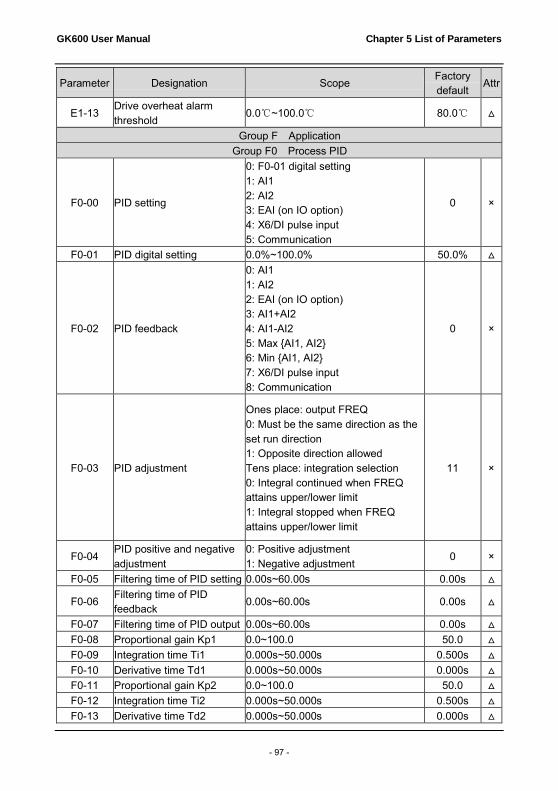
GK600 User Manual Chapter 5 List of Parameters
- 97 -
Parameter Designation Scope Factory default
Attr
E1-13 Drive overheat alarm threshold
0.0℃~100.0℃ 80.0℃ △
Group F Application Group F0 Process PID
F0-00 PID setting
0: F0-01 digital setting 1: AI1 2: AI2 3: EAI (on IO option) 4: X6/DI pulse input 5: Communication
0 ×
F0-01 PID digital setting 0.0%~100.0% 50.0% △
F0-02 PID feedback
0: AI1 1: AI2 2: EAI (on IO option) 3: AI1+AI2 4: AI1-AI2 5: Max {AI1, AI2} 6: Min {AI1, AI2} 7: X6/DI pulse input 8: Communication
0 ×
F0-03 PID adjustment
Ones place: output FREQ 0: Must be the same direction as the set run direction 1: Opposite direction allowed Tens place: integration selection 0: Integral continued when FREQ attains upper/lower limit 1: Integral stopped when FREQ attains upper/lower limit
11 ×
F0-04 PID positive and negative adjustment
0: Positive adjustment 1: Negative adjustment
0 ×
F0-05 Filtering time of PID setting 0.00s~60.00s 0.00s △
F0-06 Filtering time of PID feedback
0.00s~60.00s 0.00s △
F0-07 Filtering time of PID output 0.00s~60.00s 0.00s △ F0-08 Proportional gain Kp1 0.0~100.0 50.0 △ F0-09 Integration time Ti1 0.000s~50.000s 0.500s △ F0-10 Derivative time Td1 0.000s~50.000s 0.000s △ F0-11 Proportional gain Kp2 0.0~100.0 50.0 △ F0-12 Integration time Ti2 0.000s~50.000s 0.500s △ F0-13 Derivative time Td2 0.000s~50.000s 0.000s △

Chapter 5 List of Parameters GK600 User Manual
- 98 -
Parameter Designation Scope Factory default
Attr
F0-14 PID parameter switch
0: No switch, determined by parameters Kp1, Ti1 and Td1 1: Auto-switched on the basis of input offset 2: Switched by terminal
0 ×
F0-15 Input offset under PID auto-switch
0.0%~100.0% 20.0% △
F0-16 Sampling period T 0.001s~50.000s 0.002s △ F0-17 PID offset limit 0.0%~100.0% 0.0% △ F0-18 PID derivative limit 0.0%~100.0% 0.5% △ F0-19 PID initial value 0.0%~100.0% 0.0% ×
F0-20 PID initial value holding time
0.0s~3600.0s 0.0s △
F0-21 PID feedback loss detection value
0.0%~100.0% 0.0% △
F0-22 PID feedback loss detection time
0.0s~30.0s 1.0s △
F0-23 Cutoff FREQ when opposite to rotary set direction
0.00Hz~maximum FREQ 50.00Hz △
F0-24 PID computation option 0: No computation in stop status 1: Computation continued in stop status
0 △
Group F1 Multi-step frequency
F1-00 FREQ set source of multi-step 0
0: Digital setting F1-02 1: Digital setting b0-02 + control panel ∧/∨ adjustment 2: Digital setting b0-02 + terminal UP/DOWN adjustment 3: AI1 4: AI2 5: EAI (on IO option) 6: X6/DI pulse input 7: Process PID output 8: Communication
0 ×
F1-01 FREQ set source of multi-step 1
0: Digital setting F1-03 1: Digital setting b0-04 + control panel ∧/∨ adjustment 2: Digital setting b0-04 + terminal UP/DOWN 3: AI1 4: AI2 5: EAI (on IO option)
0 ×

GK600 User Manual Chapter 5 List of Parameters
- 99 -
Parameter Designation Scope Factory default
Attr
6: X6/DI pulse input 7: Process PID output 8: Communication
F1-02 Multi-step FREQ 0 Lower limit FREQ ~ upper limit FREQ 0.00Hz △ F1-03 Multi-step FREQ 1 Lower limit FREQ ~ upper limit FREQ 0.00 Hz △ F1-04 Multi-step FREQ 2 Lower limit FREQ ~ upper limit FREQ 0.00 Hz △ F1-05 Multi-step FREQ 3 Lower limit FREQ ~ upper limit FREQ 0.00 Hz △ F1-06 Multi-step FREQ 4 Lower limit FREQ ~ upper limit FREQ 0.00 Hz △ F1-07 Multi-step FREQ 5 Lower limit FREQ ~ upper limit FREQ 0.00 Hz △ F1-08 Multi-step FREQ 6 Lower limit FREQ ~ upper limit FREQ 0.00 Hz △ F1-09 Multi-step FREQ 7 Lower limit FREQ ~ upper limit FREQ 0.00 Hz △ F1-10 Multi-step FREQ 8 Lower limit FREQ ~ upper limit FREQ 0.00 Hz △ F1-11 Multi-step FREQ 9 Lower limit FREQ ~ upper limit FREQ 0.00 Hz △ F1-12 Multi-step FREQ 10 Lower limit FREQ ~ upper limit FREQ 0.00 Hz △ F1-13 Multi-step FREQ 11 Lower limit FREQ ~ upper limit FREQ 0.00 Hz △ F1-14 Multi-step FREQ 12 Lower limit FREQ ~ upper limit FREQ 0.00 Hz △ F1-15 Multi-step FREQ 13 Lower limit FREQ ~ upper limit FREQ 0.00 Hz △ F1-16 Multi-step FREQ 14 Lower limit FREQ ~ upper limit FREQ 0.00 Hz △ F1-17 Multi-step FREQ 15 Lower limit FREQ ~ upper limit FREQ 0.00 Hz △
Group F2 Simple PLC
F2-00 Simple PLC run mode
Ones place: PLC run mode 0: Stop after a single cycle 1: Continue to run in the last FREQ after a single cycle 2: Cycle repeated Tens place: power loss memory 0: No memory on power loss 1: Memorized on power loss Hundreds place: starting mode 0: Run from the first step “multi-step frequency 0” 1: Continue to run from the step of stop (or fault) 2: Continue to run from the step and FREQ at which run stopped (or fault occurred) Thousands place: unit of simple PLC run time 0: Second (s) 1: Minute (min)
0000 ×
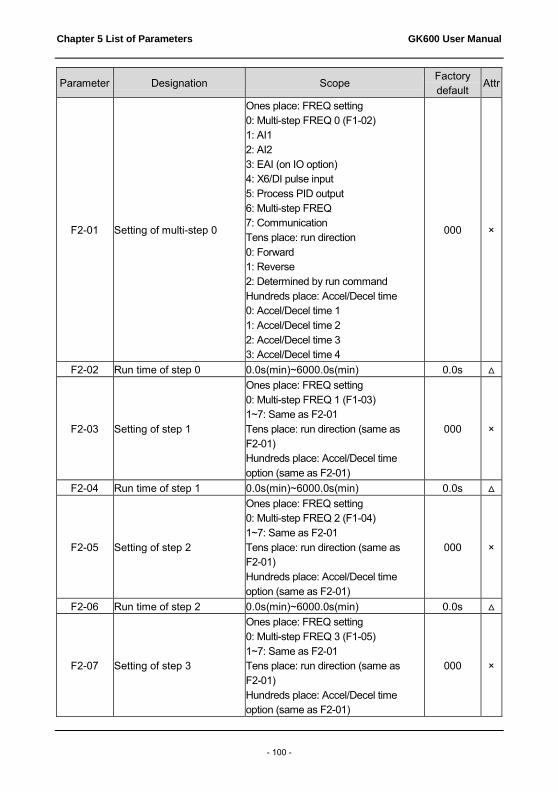
Chapter 5 List of Parameters GK600 User Manual
- 100 -
Parameter Designation Scope Factory default
Attr
F2-01 Setting of multi-step 0
Ones place: FREQ setting 0: Multi-step FREQ 0 (F1-02) 1: AI1 2: AI2 3: EAI (on IO option) 4: X6/DI pulse input 5: Process PID output 6: Multi-step FREQ 7: Communication Tens place: run direction 0: Forward 1: Reverse 2: Determined by run command Hundreds place: Accel/Decel time 0: Accel/Decel time 1 1: Accel/Decel time 2 2: Accel/Decel time 3 3: Accel/Decel time 4
000 ×
F2-02 Run time of step 0 0.0s(min)~6000.0s(min) 0.0s △
F2-03 Setting of step 1
Ones place: FREQ setting 0: Multi-step FREQ 1 (F1-03) 1~7: Same as F2-01 Tens place: run direction (same as F2-01) Hundreds place: Accel/Decel time option (same as F2-01)
000 ×
F2-04 Run time of step 1 0.0s(min)~6000.0s(min) 0.0s △
F2-05 Setting of step 2
Ones place: FREQ setting 0: Multi-step FREQ 2 (F1-04) 1~7: Same as F2-01 Tens place: run direction (same as F2-01) Hundreds place: Accel/Decel time option (same as F2-01)
000 ×
F2-06 Run time of step 2 0.0s(min)~6000.0s(min) 0.0s △
F2-07 Setting of step 3
Ones place: FREQ setting 0: Multi-step FREQ 3 (F1-05) 1~7: Same as F2-01 Tens place: run direction (same as F2-01) Hundreds place: Accel/Decel time option (same as F2-01)
000 ×

GK600 User Manual Chapter 5 List of Parameters
- 101 -
Parameter Designation Scope Factory default
Attr
F2-08 Run time of step 3 0.0s(min)~6000.0s(min) 0.0s △
F2-09 Setting of step 4
Ones place: FREQ setting 0: Multi-step FREQ 4 (F1-06) 1~7: Same as F2-01 Tens place: run direction (same as F2-01) Hundreds place: Accel/Decel time option (same as F2-01)
000 ×
F2-10 Run time of step 4 0.0s(min)~6000.0s(min) 0.0s △
F2-11 Setting of step 5
Ones place: FREQ setting 0: Multi-step FREQ 5 (F1-07) 1~7: Same as F2-01 Tens place: run direction (same as F2-01) Hundreds place: Accel/Decel time option (same as F2-01)
000 ×
F2-12 Run time of step 5 0.0s(min)~6000.0s(min) 0.0s △
F2-13 Setting of step 6
Ones place: FREQ setting 0: Multi-step FREQ 6 (F1-08) 1~7: Same as F2-01 Tens place: run direction (same as F2-01) Hundreds place: Accel/Decel time option (same as F2-01)
000 ×
F2-14 Run time of step 6 0.0s(min)~6000.0s(min) 0.0s △
F2-15 Setting of step 7
Ones place: FREQ setting 0: Multi-step FREQ 7 (F1-09) 1~7: Same as F2-01 Tens place: run direction (same as F2-01) Hundreds place: Accel/Decel time option (same as F2-01)
000 ×
F2-16 Run time of step 7 0.0s(min)~6000.0s(min) 0.0s △
F2-17 Setting of step 8
Ones place: FREQ setting 0: Multi-step FREQ 8 (F1-10) 1~7: Same as F2-01 Tens place: run direction (same as F2-01) Hundreds place: Accel/Decel time option (same as F2-01)
000 ×
F2-18 Run time of step 8 0.0s(min)~6000.0s(min) 0.0s △ F2-19 Setting of step 9 Ones place: FREQ setting 000 ×

Chapter 5 List of Parameters GK600 User Manual
- 102 -
Parameter Designation Scope Factory default
Attr
0: Multi-step FREQ 9 (F1-11) 1~7: Same as F2-01 Tens place: run direction (same as F2-01) Hundreds place: ACC/DEC time option (same as F2-01)
F2-20 Run time of step 9 0.0s(min)~6000.0s(min) 0.0s △
F2-21 Setting of step 10
Ones place: FREQ setting 0: multi-step FREQ 10 (F1-12) 1~7: same as F2-01 Tens place: run direction (same as F2-01) Hundreds place: Accel/Decel time option (same as F2-01)
000 ×
F2-22 Run time of step 10 0.0s(min)~6000.0s(min) 0.0s △
F2-23 Setting of step 11
Ones place: FREQ setting 0: Multi-step FREQ 11 (F1-13) 1~7: Same as F2-01 Tens place: run direction (same as F2-01) Hundreds place: Accel/Decel time option (same as F2-01)
000 ×
F2-24 Run time of step 11 0.0s(min)~6000.0s(min) 0.0s △
F2-25 Setting of step 12
Ones place: FREQ setting 0: Multi-step FREQ 12 (F1-14) 1~7: Same as F2-01 Tens place: run direction (same as F2-01) Hundreds place: Accel/Decel time option (same as F2-01)
000 ×
F2-26 Run time of step 12 0.0s(min)~6000.0s(min) 0.0s △
F2-27 Setting of step 13
Ones place: FREQ setting 0: Multi-step FREQ 13 (F1-15) 1~7: Same as F2-01 Tens place: run direction (same as F2-01) Hundreds place: Accel/Decel time option (same as F2-01)
000 ×
F2-28 Run time of step 13 0.0s(min)~6000.0s(min) 0.0s △
F2-29 Setting of step 14 Ones place: FREQ setting 0: Multi-step FREQ 14 (F1-16) 1~7: Same as F2-01
000 ×

GK600 User Manual Chapter 5 List of Parameters
- 103 -
Parameter Designation Scope Factory default
Attr
Tens place: run direction (same as F2-01) Hundreds place: Accel/Decel time option (same as F2-01)
F2-30 Run time of step 14 0.0s(min)~6000.0s(min) 0.0s △
F2-31 Setting of step 15
Ones place: FREQ setting 0: Multi-step FREQ 15 (F1-17) 1~7: Same as F2-01 Tens place: run direction (same as F2-01) Hundreds place: Accel/Decel time option (same as F2-01)
000 ×
F2-32 Run time of step 15 0.0s(min)~6000.0s(min) 0.0s △ Group F3 Wobble Frequency and Fixed Length Count
F3-00 Wobble FREQ function setting
0: Wobble FREQ function disabled 1: Wobble FREQ function enabled
0 ×
F3-01 Wobble FREQ run setting
Ones place: started method 0: Automatically 1: Started by terminal Tens place: amplitude control 0: Relative to center FREQ 1: Relative to maximum FREQ Hundreds place: wobble FREQ memorized when stop 0: Memory enabled 1: Memory disabled Thousands place: wobble FREQ memorized on power loss 0: Memory enabled 1: Memory disabled
0000 ×
F3-02 Pre-wobble FREQ 0.00Hz~600.00Hz 0.00Hz △
F3-03 Pre-wobble FREQ holding time
0.0s~3600.0s 0.0s △
F3-04 Wobble FREQ amplitude 0.0%~50.0% 0.0% △ F3-05 Hop FREQ 0.0%~50.0% (relative to F3-04) 0.0% △ F3-06 Cycle of wobble FREQ 0.1s~999.9s 0.0s △
F3-07 Triangular wave ramp-up time
0.0%~100.0% (of wobble FREQ cycle)
0.0% △
F3-08 Length unit 0: m 1: 10m
0 △
F3-09 Length setting 0~65535 1000 △ F3-10 Pulse number per meter 0.1~6553.5 100.0 △

Chapter 5 List of Parameters GK600 User Manual
- 104 -
Parameter Designation Scope Factory default
Attr
F3-11 Action when the length attained
0: Not stop 1: Stop
0 △
F3-12 Set count value 1~65535 1000 △ F3-13 Designated count value 1~65535 1000 △
Group H Communication Parameters Group H0 MODBUS Communication Parameters
H0-00 SCI port selection 0: Local 485 port 1: Optional 232 port
0 ×
H0-01 SCI port communication configuration
Ones place: baud rate 0: 4800bps 1: 9600bps 2: 19200bps 3: 38400bps 4: 57600bps 5: 115200bps Tens place: data format 0: 1-8-2-N format, RTU 1: 1-8-1-E format, RTU 2: 1-8-1-O Format, RTU 3: 1-7-2-N format, ASCII 4: 1-7-1-E format, ASCII 5: 1-7-1-O format, ASCII Hundreds place: connection type 0: Direct cable connection (232/485) 1: MODEM (232) Thousands place: communication data handling at power loss 0: Saved at power loss 1: Not saved at power loss
0001 ×
H0-02 Local address of SCI port communication
0~247, 0 is broadcast address 1 ×
H0-03 Time out detection of SCI port communication
0.0s~1000.0s 0.0s ×
H0-04 Time delay of SCI port communication
0ms~1000ms 0ms ×
H0-05 Master/Slave option 0: PC controls this drive 1: As master 2: As slave
0 ×
H0-06 Parameter store address when this drive working as master
0:b0-02 1:F0-01
0 ×

GK600 User Manual Chapter 5 List of Parameters
- 105 -
Parameter Designation Scope Factory default
Attr
H0-07 Proportional factor of received FREQ
0.0~1000.0% 100.0% △
Group H1 Profibus-DP Communication Parameters H1-00 Local address 1~126; 127 is broadcast address 4 △
H1-01 PPO type
0: Profibus disabled 1: PPO1 2: PPO2 3: PPO3 4: PPO4 5: PPO5
0 △
H1-02 PZD2_OUT(the master →
the slave)
0: none 0x6200~0x6214 0 △
H1-03 PZD3_OUT(the master →
the slave)
0: none 0x6200~0x6214 0 △
H1-04 PZD4_OUT(the master →
the slave)
0: none 0x6200~0x6214 0 △
H1-05 PZD5_OUT(the master →
the slave)
0: none 0x6200~0x6214 0 △
H1-06 PZD6_OUT(the master →
the slave)
0: none 0x6200~0x6214 0 △
H1-07 PZD7_OUT(the master →
the slave)
0: none 0x6200~0x6214 0 △
H1-08 PZD8_OUT(the master →
the slave)
0: none 0x6200~0x6214 0 △
H1-09 PZD9_OUT(the master →
the passive)
0: none 0x6200~0x6214 0 △
H1-10 PZD10_OUT(the master →
the slave)
0: none 0x6200~0x6214 0 △
H1-11 PZD2_IN(the slave → the
master)
0: none A0-00~U2-xx 0x6200~0x6214;0x6300~0x6323
0 △
H1-12 PZD3_IN(the slave → the
master)
0: none A0-00~U2-xx; 0x6200~0x6214;0x6300~0x6323
0 △

Chapter 5 List of Parameters GK600 User Manual
- 106 -
Parameter Designation Scope Factory default
Attr
H1-13 PZD4_IN(the slave → the
master)
0: none A0-00~U2-xx 0x6200~0x6214;0x6300~0x6323
0 △
H1-14 PZD5_IN(the slave → the
master)
0: none A0-00~U2-xx 0x6200~0x6214;0x6300~0x6323
0 △
H1-15 PZD6_IN(the slave → the
master)
0: none A0-00~U2-xx 0x6200~0x6214;0x6300~0x6323
0 △
H1-16 PZD7_IN(the slave → the
master)
0: none A0-00~U2-xx 0x6200~0x6214;0x6300~0x6323
0 △
H1-17 PZD8_IN(the slave → the
master)
0: none A0-00~U2-xx 0x6200~0x6214;0x6300~0x6323
0 △
H1-18 PZD9_IN(the slave → the
master)
0: none A0-00~U2-xx 0x6200~0x6214;0x6300~0x6323
0 △
H1-19 PZD10_IN(the slave → the
master)
0: none A0-00~U2-xx 0x6200~0x6214;0x6300~0x6323
0 △
H1-20 Operation at bus fault 0: No action 1: Stop 0 △
Group L Keys and Display of Control panel Group L0 Keys of Control panel
L0-00 MF key setting
0: No function 1: Forward jog 2: Reverse jog 3: Forward/reverse switchover 4: Emergency stop 1 (set Decel time by b2-09) 5: Emergency stop 2 (coast to stop) 6: Run command sources shifted
0 △
L0-01 Keys locked option
0: Not locked 1: All locked 2: Keys locked except RUN, STOP/RESET 3: Keys locked except STOP/RESET 4: Keys locked other than >>
0 △
L0-02 Function of STOP key
0: STOP key active only at control panel control 1: STOP key deactivated under any command source
0 △

GK600 User Manual Chapter 5 List of Parameters
- 107 -
Parameter Designation Scope Factory default
Attr
L0-03 FREQ adjustment through keys ∧/∨
Ones place: option at stop 0: Clear at stop 1: Holding at stop Tens place: option at power loss 0: Clear at power loss 1: Holding at power loss Hundreds place: integrating option 0: Integrating disabled 1: Integrating enabled Thousands place: run direction 0: Direction changing prohibited 1: Direction changing permitted
0100 △
L0-04 Step size of FREQ adjustment through keys ∧/∨
0.00Hz/s~10.00Hz/s 0.03 Hz/s △
Group L1 Control Panel Display Setting
L1-00 Display parameter setting 1 on run status
Binary system setting: 0: No display 1: Display Ones place: BIT0: Run FREQ (Hz) BIT1: Set FREQ (Hz) BIT2: Bus voltage (V) BIT3: Output current (A) Tens place: BIT0: Output torque (%) BIT1: Output power (kW) BIT2: Output voltage (V) BIT3: Motor speed (r/min) Hundreds place: BIT0: AI1 (V) BIT1: AI2 (V) BIT2: EAI (V) BIT3: Output sync FREQ (Hz) Thousands place: BIT0: DI BIT1: External count value BIT2: Reserved BIT3: Reserved Note: when this parameter value is set to 0000, run FREQ (Hz) would be displayed as default
080F
△

Chapter 5 List of Parameters GK600 User Manual
- 108 -
Parameter Designation Scope Factory default
Attr
L1-01 Display parameter setting 2 on run status
Binary system setting: 0: No display 1: Display Ones place: BIT0: Run linear speed (m/s) BIT1: Set linear speed (m/s) BIT2: Input terminal status BIT3: Output terminal status Tens place: BIT0: PID setting (%) BIT1: PID feedback (%) BIT2: Set length (m) BIT3: Actual length (m) Hundreds place: reserved Thousands place: reserved
0000 △
L1-02 Display parameter setting on stop status
Binary system setting: 0: No display 1: Display Ones place: BIT0: FREQ setting (Hz) BIT1: Bus voltage (V) BIT2: Input terminal status BIT3: Output terminal status Tens place: BIT0: AI1 (V) BIT1: AI2 (V) BIT2: EAI (V) BIT3: Reserved Hundreds place: BIT0: PID setting (%) BIT1: PID feedback (%) BIT2: Set length (m) BIT3: Actual length (m) Thousands place: BIT0: Run linear speed (m/s) BIT1: Set linear speed (m/s) BIT2: External count value BIT3: DI Note: when this parameter value is set to 0000, the set FREQ would be displayed as default (Hz)
0003 △
L1-03 Linear speed COEFF 0.1%~999.9% 100.0% △

GK600 User Manual Chapter 5 List of Parameters
- 109 -
Parameter Designation Scope Factory default
Attr
Group U Monitoring Group U0 Status Monitoring
U0-00 Run FREQ 0.00Hz~600.00Hz 0.00Hz ◎ U0-01 Set FREQ 0.00Hz~600.00Hz 0.00Hz ◎ U0-02 Bus voltage 0V~65535V 0V ◎ U0-03 Output voltage 0V~65535V 0V ◎ U0-04 Output current 0.0A~6553.5A 0.0A ◎ U0-05 Output torque -300.0%~300.0% 0.0% ◎ U0-06 Output power 0.0%~300.0% 0.0% ◎
U0-07 Master FREQ set source
0: Digital setting + adjustment through ∧/∨ on control panel 1: Digital setting + terminal UP/DOWN adjustment 2: Analog input AI1 3: Analog input AI2 4: Analog input EAI 5: X6/DI pulse input 6: Process PID output 7: PLC 8: Multi-step FREQ 9: Communication
0 ◎
U0-08 Auxiliary FREQ set source
0: No set 1: Digital setting + adjustment through ∧/∨ on control panel 2: Digital setting + terminal UP/DOWN adjustment 3: Analog input AI1 4: Analog input AI2 5: Analog input EAI 6: X6/DI pulse input 7: Process PID output 8: PLC 9: Multi-step FREQ 10: Communication
0 ◎
U0-09 Master FREQ setting 0.00Hz~600.00Hz 0.00Hz ◎ U0-10 Auxiliary FREQ setting 0.00Hz~600.00Hz 0.00Hz ◎
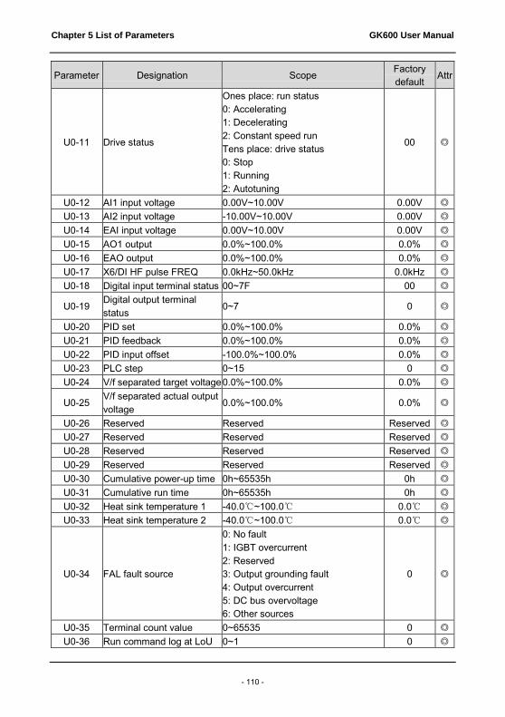
Chapter 5 List of Parameters GK600 User Manual
- 110 -
Parameter Designation Scope Factory default
Attr
U0-11 Drive status
Ones place: run status 0: Accelerating 1: Decelerating 2: Constant speed run Tens place: drive status 0: Stop 1: Running 2: Autotuning
00 ◎
U0-12 AI1 input voltage 0.00V~10.00V 0.00V ◎ U0-13 AI2 input voltage -10.00V~10.00V 0.00V ◎ U0-14 EAI input voltage 0.00V~10.00V 0.00V ◎ U0-15 AO1 output 0.0%~100.0% 0.0% ◎ U0-16 EAO output 0.0%~100.0% 0.0% ◎ U0-17 X6/DI HF pulse FREQ 0.0kHz~50.0kHz 0.0kHz ◎ U0-18 Digital input terminal status 00~7F 00 ◎
U0-19 Digital output terminal status
0~7 0 ◎
U0-20 PID set 0.0%~100.0% 0.0% ◎ U0-21 PID feedback 0.0%~100.0% 0.0% ◎ U0-22 PID input offset -100.0%~100.0% 0.0% ◎ U0-23 PLC step 0~15 0 ◎ U0-24 V/f separated target voltage 0.0%~100.0% 0.0% ◎
U0-25 V/f separated actual output voltage
0.0%~100.0% 0.0% ◎
U0-26 Reserved Reserved Reserved ◎ U0-27 Reserved Reserved Reserved ◎ U0-28 Reserved Reserved Reserved ◎ U0-29 Reserved Reserved Reserved ◎ U0-30 Cumulative power-up time 0h~65535h 0h ◎ U0-31 Cumulative run time 0h~65535h 0h ◎ U0-32 Heat sink temperature 1 -40.0℃~100.0℃ 0.0℃ ◎ U0-33 Heat sink temperature 2 -40.0℃~100.0℃ 0.0℃ ◎
U0-34 FAL fault source
0: No fault 1: IGBT overcurrent 2: Reserved 3: Output grounding fault 4: Output overcurrent 5: DC bus overvoltage 6: Other sources
0 ◎
U0-35 Terminal count value 0~65535 0 ◎ U0-36 Run command log at LoU 0~1 0 ◎

GK600 User Manual Chapter 5 List of Parameters
- 111 -
Parameter Designation Scope Factory default
Attr
U0-37 Fault code log at LoU 0~100 0 ◎ U0-38 Reserved Reserved Reserved ◎
U0-39 CtC fault source
0: No fault 1: U-phase current detection circuit fault 2: V-phase current detection circuit fault 3: W-phase current detection circuit fault
0 ◎
U0-40 Higher-bit numbers of actual length
0~65 0 ◎
U0-41 Lower-bit numbers of actual length
0~65535 0 ◎
U0-42 Higher-bit numbers of control panel ∧/∨ stored value
-1~1 0 ◎
U0-43 Lower-bit numbers of control panel ∧/∨ stored value
0.00~655.35 Hz 0.00Hz ◎
U0-44 Higher-bit numbers of terminal UP/DOWN stored value
-1~1 0 ◎
U0-45 Lower-bit numbers of terminal UP/DOWN stored value
0.00~655.35 Hz 0.00Hz ◎
U0-46 Reserved Reserved Reserved ◎ U0-47 Reserved Reserved Reserved ◎ U0-48 Reserved Reserved Reserved ◎ U0-49 Reserved Reserved Reserved ◎ U0-50 Reserved Reserved Reserved ◎ U0-51 Reserved Reserved Reserved ◎
U0-52 Center FREQ of wobble FREQ
0~600.00 Hz 0.00 Hz ◎
U0-53 Reserved Reserved Reserved ◎ U0-54 Reserved Reserved Reserved ◎ U0-55 Reserved Reserved Reserved ◎
Group U1 History Fault
U1-00 History fault 1 (latest)
0: No fault 1: Accel overcurrent (oC1) 2: Constant-speed overcurrent (oC2) 3: Decel overcurrent (oC3)
0 ◎

Chapter 5 List of Parameters GK600 User Manual
- 112 -
Parameter Designation Scope Factory default
Attr
4: Accel overvoltage (ov1) 5: Constant-speed overvoltage (ov2) 6: Decel overvoltage (ov3) 7: Module protection (FAL) 8: Autotuning failed (tUN) 9: Drive overloaded (oL1) 10: Motor overloaded (oL2) 11: Current detection abnormal (CtC) 12: Ground short-circuit protection at output side (GdP) 13: Input power supply fault (ISF) 14: Phase loss at output side (oPL) 15: Inverter module overloaded (oL3) 16: Module overheated (oH1) 17: Motor overheated (PTC) (oH2) 18: Module temperature detection disconnection (oH3) 19: Reserved 20: Abnormal option board connection (EC1) 21: Reserved 22: Control board flat cable connection abnormal (dLC) 23: Analog terminal functional mutex (TEr) 24: External equipment malfunction (PEr) 25: Reserved 26: Continuous run time attained (to2) 27: Accumulative run time attained (to3) 28: Power supply abnormal in running (SUE) 29: EEPROM read/write fault (EPr) 30: Contactor close fault (CCL) 31: Port communication abnormal (TrC) 32: Control panel communication abnormal (PdC) 33: Parameter copy fault (CPy) 34: Reserved 35: Software version compatibility

GK600 User Manual Chapter 5 List of Parameters
- 113 -
Parameter Designation Scope Factory default
Attr
fault (SFt) 36: CPU interference as a fault (CPU) 37: Overcurrent reference fault (oCr) 38: 5V power supply out-of-limit (SP1) 39: 10V power supply out-of-limit (SP1) 40: AI input out-of-limit (AIP) 41: Undervoltage protection (LoU) 42-44: Reserved 45: PID feedback loss (PIo) 46: Profibus communication abnormal (PFS)
U1-01 Run frequency at fault 1 0.00Hz~600.00Hz 0.00Hz ◎ U1-02 Output current at fault 1 0.0A~6553.5A 0.0A ◎ U1-03 Bus voltage at fault 1 0V~10000V 0V ◎
U1-04 Temperature 1 of heat sink at fault 1
-40.0℃~100.0℃ 0.0℃ ◎
U1-05 Temperature 2 of heat sink at fault 1
-40.0℃~100.0℃ 0.0℃ ◎
U1-06 Input terminal status at fault 1
0~FFFF 0000 ◎
U1-07 Output terminal status at fault 1
0~FFFF 0000 ◎
U1-08 Cumulative run time at fault 1
0h~65535h 0h ◎
U1-09 Code of fault 2 Same as U1-00 0 ◎ U1-10 Run frequency at fault 2 0.00Hz~600.00Hz 0.00Hz ◎ U1-11 Output current at fault 2 0.0A~6553.5A 0.0A ◎ U1-12 Bus voltage at fault 2 0V~10000V 0V ◎
U1-13 Temperature 1 of heat sink at fault 2
-40.0℃~100.0℃ 0.0℃ ◎
U1-14 Temperature 2 of heat sink at fault 2 -40.0℃~100.0℃ 0.0℃ ◎
U1-15 Input terminal status at fault 2
0~FFFF 0000 ◎
U1-16 Output terminal status at fault 2 0~FFFF 0000 ◎
U1-17 Cumulative run time at fault 2
0h~65535h 0h ◎
U1-18 Code of fault 3 Same as U1-00 0 ◎

Chapter 5 List of Parameters GK600 User Manual
- 114 -
Parameter Designation Scope Factory default
Attr
U1-19 Run frequency at fault 3 0.00Hz~600.00Hz 0.00Hz ◎ U1-20 Output current at fault 3 0.0A~6553.5A 0.0A ◎ U1-21 Bus voltage at fault 3 0V~1000V 0V ◎
U1-22 Temperature 1 of heat sink at fault 3
-40.0℃~100.0℃ 0.0℃ ◎
U1-23 Temperature 2 of heat sink at fault 3
-40.0℃~100.0℃ 0.0℃ ◎
U1-24 Input terminal status at fault 3
0~FFFF 0000 ◎
U1-25 Output terminal status at fault 3
0~FFFF 0000 ◎
U1-26 Cumulative run time at fault 3
0h~65535h 0h ◎

GK600 User Manual Chapter 6 Specification of Parameters
- 115 -
Chapter 6 Specification of Parameters
Group A System Parameters and Parameter Management
Group A0 System Parameters
A0-00 Setting of user password Range: 0~FFFF Factory default:
0000
Setting of password:
A non-zero four-digital number could be set as a user password by entering this password into A0-00 and pressing ENT key to confirm once, then reenter and reconfirm it once again within 10 seconds. Once this password has been successfully set, the word "P-SEt" would be displayed. The password setting will take effect as long as there is no operation on control panel within 5 minutes, or cutting the power off and power up again.
Change password:
Access A0-00 after entering the original four-digit password (at this point, A0-00 displays 0000) and set the new password following the above-noted procedure.
Password clearance:
Access A0-00 after entering the original four-digit password (at this point, A0-00 displays 0000), enter 0000 twice and press ENT key to make confirmation. In this way, password is successfully cleared and the word "P-CLr" is displayed.
A0-01 Parameter display Range: 0~3 Factory default:
0
This parameter sets the display/hide of parameters. 0: Display all parameters (A1-20~A1-21 parameter display/hide is valid) 1: Only display A0-00 and A0-01 2: Only display A0-00, A0-01 and user-defined A1-00~A1-19 3: Only display A0-00, A0-01, and the parameters different from factory default
A0-02 Parameter protection Range: 0~1 Factory default:
0
0: All parameter programming allowed 1: Only A0-00 and this parameter programming allowed When this parameter is set to 1, all parameters other than A0-00 and A0-02 are not allowed to modify. Set A0-02 to 0 before the modification of other parameters.

Chapter 6 Specification of Parameters GK600 User Manual
- 116 -
A0-03 Parameter restoration Range: 0~4 Factory default:
0
0: No operation 1: Clear fault record When this parameter is set to 1, all fault record of Group U1 will be cleared. 2: Restore all parameters to factory default (excluding motor parameters) 3: Restore all parameters to factory default (including motor parameters) 4: Restore all parameters to backup parameters
A0-04 Parameter backup Range: 0~1 Factory default:
0
0: No operation 1: Backup all parameters
A0-05 Parameter copy Range: 0~3 Factory default:
0
0: No operation 1: Upload all parameters other than Group U to control panel 2: Download all parameters of control panel other than d0-01~d0-18 and d3-01~d3-18 to drive 3: Download all parameters of control panel to drive
A0-06 Type of drive Range: 0~1 Factory default:
0
0: Type G (applicable to constant-torque load) 1: Type L (applicable to light-duty load)
A0-07 Power supply type of
SMPS Range: 0~1
Factory default: 0
0: Supplied by DC bus voltage of drive main circuit
The switching power supply inside the drive is supplied by DC bus voltage. 1: Supplied independently
The switching power supply inside the drive is not supplied by DC bus voltage, while it is supplied by independent rectifier circuit or battery, and in such circumstance, option board EPC-VD2 is required for detecting the DC bus voltage of main circuit. This setting is usually for occasions that the work of drive control circuit cannot be stopped at power loss.
A0-08 Motor 1 / motor 2
selection Range: 0~1
Factory default: 0
0: Motor 1
Selects the current loaded motor as motor 1. Set the parameters of motor 1 in parameter

GK600 User Manual Chapter 6 Specification of Parameters
- 117 -
groups d0~d2. 1: Motor 2
Selects the current loaded motor as motor 2. Set the parameters of motor 1 in parameter groups d3~d5. The current loaded motor can also be selected through digital input terminal "motor 1/2 switchover" as shown in Table 6-1:
Table 6-1
A0-08 Motor 1/2 switchover
terminal Motor selection
0 OFF Motor 1
0 ON Motor 2
1 OFF Motor 2
1 ON Motor 1
A0-09 Motor control technique Range: 00~22 Factory default:
00
Ones place: motor 1 control technique 0: V/f control
Constant Volt/Hertz ratio control: Applicable to such cases in which the performance requirement to the drive is not rigorous, or using one drive to drive several motors, or it is difficult to identify motor parameters correctly, etc. When motor 1 under V/f control is selected, need to set related parameters group d1 well.
1: Sensor-less vector control 1 This helps achieve high-performance control without encoder and provides strong adaptability of load. Under this selection, please correctly set motor parameters of Group d0 and vector control parameters of Group d2. Sensor-less vector control 1 is robust vector control. If motor rotary autotuning is not able to be performed or permitted, sensor-less vector control 1 performance would be relatively ideal than sensor-less vector control 2.
2: Sensor-less vector control 2 This helps achieve high-performance control without encoder. This control technique is superior to sensor-less vector control 1. Under this selection, please correctly set motor parameters of Group d0 and vector control parameters of Group d2. Sensor-less vector control 2 is precise vector control and it requires motor rotary autotuning.
Tens place: motor 2 control technique 0: V/f control
Constant Volt/Hertz ratio control: Applicable to such cases in which the performance requirement to the drive is not rigorous, or using one drive to drive several motors, or it is difficult to identify motor parameters correctly, etc. When motor 1 under V/f control is selected, need to set related parameters group d4 well.

Chapter 6 Specification of Parameters GK600 User Manual
- 118 -
1: sensor-less vector control 1 This helps achieve high-performance control without encoder and provides strong adaptability of load. Under this selection, please correctly set motor parameters of Group d3 and vector control parameters of Group d5. Sensor-less vector control 1 is robust vector control. If motor rotary autotuning is not able to be performed or permitted, sensor-less vector control 1 performance would be relatively ideal than sensor-less vector control 2.
2: Sensor-less vector control 2 This helps achieve high-performance control without encoder. This control technique is superior to sensor-less vector control 1. Under this selection, please correctly set motor parameters of Group d3 and vector control parameters of Group d5. Under this selection, please correctly set motor parameters of Group d0 and vector control parameters of Group d2. Sensor-less vector control 2 is precise vector control and it requires motor rotary autotuning.
ATTENTION: When vector control mode is selected, it is necessary to perform motor parameter identification in order to obtain correct motor parameters before initial running. Upon the completion of normal process of motor parameter identification, automatically acquired motor parameters will be stored into drive for control operation during running.
It should be noted when vector control is selected that one drive can only be used to drive one motor. The capacity gap between the drive and the motor should not be excessively big. Added to this, the power of motor could be two classes lower or one class higher than its matching drive. Failure to comply will be most likely to result in performance degradation or abnormal working.
Group A1 User-defined Display Parameters
A1-00 User-defined display parameter 1
Range: A0-00~U1-26 Factory default: A0-00
A1-01 User-defined display parameter 2
Range: A0-00~U1-26 Factory default: A0-00
A1-02 User-defined display parameter 3
Range: A0-00~U1-26 Factory default: A0-00
A1-03 User-defined display parameter 4
Range: A0-00~U1-26 Factory default: A0-00
A1-04 User-defined display parameter 5
Range: A0-00~U1-26 Factory default: A0-00
A1-05 User-defined display parameter 6
Range: A0-00~U1-26 Factory default: A0-00
A1-06 User-defined display parameter 7
Range: A0-00~U1-26 Factory default: A0-00

GK600 User Manual Chapter 6 Specification of Parameters
- 119 -
A1-07 User-defined display parameter 8
Range: A0-00~U1-26 Factory default: A0-00
A1-08 User-defined display parameter 9
Range: A0-00~U1-26 Factory default: A0-00
A1-09 User-defined display parameter 10
Range: A0-00~U1-26 Factory default: A0-00
A1-10 User-defined display parameter 11
Range: A0-00~U1-26 Factory default: A0-00
A1-11 User-defined display parameter 12
Range: A0-00~U1-26 Factory default: A0-00
A1-12 User-defined display parameter 13
Range: A0-00~U1-26 Factory default: A0-00
A1-13 User-defined display parameter 14
Range: A0-00~U1-26 Factory default: A0-00
A1-14 User-defined display parameter 15
Range: A0-00~U1-26 Factory default: A0-00
A1-15 User-defined display parameter 16
Range: A0-00~U1-26 Factory default: A0-00
A1-16 User-defined display parameter 17
Range: A0-00~U1-26 Factory default: A0-00
A1-17 User-defined display parameter 18
Range: A0-00~U1-26 Factory default: A0-00
A1-18 User-defined display parameter 19
Range: A0-00~U1-26 Factory default: A0-00
A1-19 User-defined display parameter 20
Range: A0-00~U1-26 Factory default: A0-00
A1-00~A1-19 set values would not take effect unless A0-01 is set to 2 Setting range of thousands place: A, b, C, d, E, F, H, L, U Setting range of hundreds place: 0~9; Setting range of tens place: 0~9; Setting range of ones place: 0~9.
Example:
To exclusively display parameters A0-00, A0-01, b0-01, E0-01 and F0-01, it is merely necessary to set A1-00 to b0-01, A1-01 to E0-01, A1-02 to F0-01 and A1-03~A1-19 to A0-00 and then set A0-01 to 2.
A1-20 Parameter group display/hide setting 1
Range: 0000~FFFF Factory default: FFFF
A1-21 Parameter group display/hide setting 2
Range: 0000~FFFF Factory default: FFFF

Chapter 6 Specification of Parameters GK600 User Manual
- 120 -
When A0-01 is set to ‘0’ to display all parameters, only the parameters whose bit corresponding to A1-20 and A1-21 is 1 can be displayed.
The parameters that correspond to bit 15 (the highest bit of binary system) ~ bit 0 (the lowest bit of binary system) of A1-20 are shown as table 6-2.
Table 6-2
bit15 bit14 bit13 bit12 bit11 bit10 bit9 bit8
E0 d6 d5 d4 d3 d2 d1 d0
bit7 bit6 bit5 bit4 bit3 bit2 bit1 bit0
C4 C3 C2 C1 C0 b2 b1 b0
The parameters that correspond to bit 15 (the highest bit of binary system) ~ bit 0 (the lowest bit of binary system) of A1-21 are shown as follows:
Table 6-3
bit15 bit14 bit13 bit12 bit11 bit10 bit9 bit8
U2 U1 U0 L1 L0 H2 H1 H0
bit7 bit6 bit5 bit4 bit3 bit2 bit1 bit0
F6 F5 F4 F3 F2 F1 F0 E1
ATTENTION: Parameters of Groups A0 and A1 are always displayed and are not subject to A1-20 and A1-21 show/hide control.
Example:
Besides parameter Groups A0 and A1, the groups b0, b1, b2, C0, C1, C2, C3, d0, d1 and E1 are also requested to display, just set: A1-20 to 037F (A1-20 is 0000 0011 0111 1111 in binary) A1-21 to 0001 (A1-21 is 0000 0000 0000 0001 in binary)
Group b Run Parameter Setting
Group b0 Frequency Setting
Frequency setting is set by parameter Group b0. See Fig. 6-1 for logical relation of FREQ set.
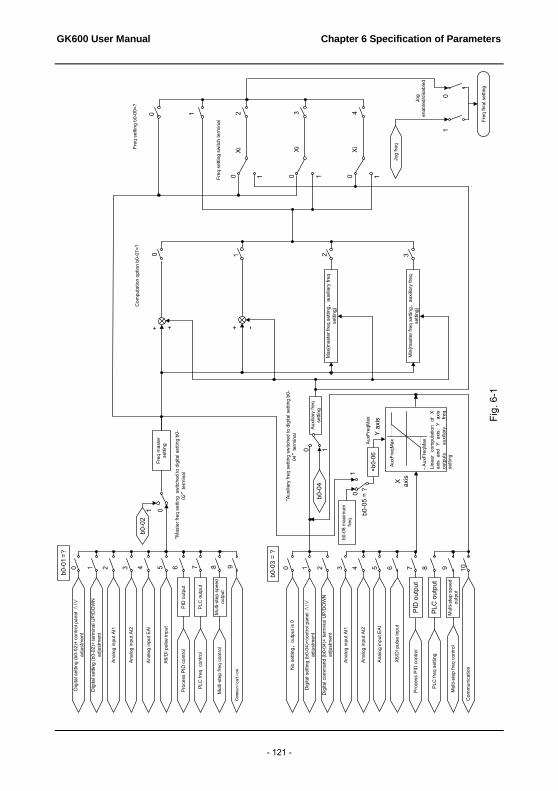
GK600 User Manual Chapter 6 Specification of Parameters
- 121 -
Anal
og in
put A
I1
Mul
ti-st
ep fr
eq c
ontro
l
PLC
freq
con
trol
Proc
ess
PID
con
trol
X6/D
I pul
se in
put
Anal
og in
put E
AI
Anal
og in
put A
I2
Communication
PID
out
put
PLC
out
put
Mul
ti-st
ep s
peed
ou
tput
b0-0
2
“M
aste
r fre
q se
tting
sw
itche
d to
dig
ital s
ettin
g b0
-02
”te
rmin
al
0
Anal
og in
put A
I1
Mul
ti-st
ep fr
eq c
ontro
l
PLC
freq
set
ting
Proc
ess
PID
con
trol
Dig
ital s
ettin
g (b
0-04
)+co
ntro
l pan
el ∧
/∨
adju
stm
ent
Dig
ital c
omm
and
(b0-
04)+
term
inal
UP/
DO
WN
ad
just
men
t
X6/
DI p
ulse
inpu
t
Anal
og in
put E
AI
Anal
og in
put A
I2
Com
mun
icat
ion
b0-0
4
“Au
xilia
ry fr
eq s
ettin
g sw
itche
d to
dig
ital s
ettin
g b0
-04
”te
rmin
al
0
No
setti
ng,
outp
ut is
0
b0-0
8 m
axim
um
freq
×b0-
06
AuxF
reqM
ax
- Aux
Freq
MaxAu
xFre
qMax
X axis
Y a
xis
b0-0
5 =
?01
9876543210
b0-0
3 =
?
10987654310 2
Line
ar
com
puta
tion
of
X ax
is a
nd Y
axi
s. Y
axi
s ou
tput
s au
xilia
ry
freq
setti
ng
Auxi
liary
freq
se
tting
Freq
mas
ter
setti
ng
b0-0
1 = ?
+ -++
Max
{mas
ter f
req
setti
ng,
auxi
liary
freq
se
tting
}
Min
{mas
ter f
req
setti
ng,
auxi
liary
freq
se
tting
}
1
Com
puta
tion
optio
n b0
-07=
?
0 1 2 3
0 1 0 1 10
0 1 2 3 4
Jog
freq
Jog
enab
led/
disa
bled
01
Freq
fina
l set
ting
Freq
set
ting
b0-0
0=?
Xi Xi Xi
Freq
set
ting
switc
h te
rmin
al
1
Dig
ital s
ettin
g (b
0-02
)+ te
rmin
al U
P/D
OW
N
adju
stm
ent
PID
out
put
PLC
out
put
Mul
ti-st
ep s
peed
ou
tput
Fig.
6-1
Dig
ital s
ettin
g (b
0-02
)+ c
ontro
l pan
el ∧
/∨
adju
stm
ent

Chapter 6 Specification of Parameters GK600 User Manual
- 122 -
b0-00 Frequency set mode Range: 0~4 Factory default:
0
0: Master FREQ set Output frequency of drive is determined by master frequency set source b0-01. Refer to parameters b0-01 and b0-02 for further information.
1: Master & auxiliary computation result Frequency set is the result of master & auxiliary computation. The master & auxiliary computation relation is determined by b0-07. Master frequency is set by b0-01, while auxiliary is set by b0-03.
2: Switch between master and auxiliary set When b0-00 is set to 2, the switch between master frequency set, and auxiliary frequency set can be realized through digital input terminal "frequency set switchover". When terminal "frequency set switchover" is invalid, frequency set of the drive will be determined by b0-01. When terminal "frequency set switchover" is valid, frequency set of the drive will be determined by b0-03 (Auxiliary frequency set source).
3: Switch between master FREQ set, and master & auxiliary computation result When b0-00 is set to 3, frequency is determined by master frequency set, or master & auxiliary computation result through digital input terminal "frequency set switchover". When terminal "frequency set switchover" is invalid, frequency is determined by b0-01 (master frequency set source). When terminal "frequency set switchover" is valid, frequency is determined by master & auxiliary computation result. The master & auxiliary computation relation is determined by b0-07.
4: Switch between auxiliary FREQ set, and master & auxiliary computation result When b0-00 is set to 4, frequency is determined by auxiliary frequency set, or master & auxiliary computation result through digital input terminal “frequency set switchover”. When terminal "frequency set switchover" is invalid, frequency is determined by b0-03 (auxiliary frequency set source). When terminal "frequency set switchover" is valid, frequency is determined by master & auxiliary computation result. The master & auxiliary computation relation is determined by b0-07.
b0-01 Master frequency set Range: 0~9 Factory default:
0
0: Digital setting (b0-02) + ∧/∨ adjustment on control panel When the drive is powered up, the value of b0-02 is taken as the master frequency set which can be adjusted through ∧/∨ keys on control panel no matter the drive is running or in stop.

GK600 User Manual Chapter 6 Specification of Parameters
- 123 -
ATTENTION: Frequency adjustment via ∧/∨ on control panel can be cleared through terminal "UP/DOWN (including ∧/∨ key) adjustment clear " . Refer to C0-01~C0-10 for details.
1: Digital setting (b0-02) + terminal UP/DOWN adjustment When the drive is powered up, the value of b0-02 is taken as the master frequency set. This frequency can be adjusted via “terminal UP” and “terminal DOWN” no matter the drive is running or in stop.
When this parameter value is selected, following parameter setting should be performed: 1) Set the two digital input terminals to "terminal UP" and "terminal DOWN" respectively.
Refer to C0-01~C0-10 for further information. 2) Set terminal UP/DOWN frequency change step size (C0-18). 3) Set C0-17 (terminal UP/DOWN frequency adjustment treatment).
ATTENTION: Frequency adjustment via terminal UP and DOWN can be cleared through terminal "UP/DOWN (including ∧/∨ key) adjustment clear" . Refer to C0-01~C0-10 for details.
2: Analog input AI1 (0~10V) voltage input and (0~20mA) current input are optional for AI1, which can be selected using jumper switch S2 on control board. It is shown as Figure 6-2.
Fig. 6-2
Refer to specification of C2-00~C2-20 for corresponding relation between analog input and output frequency. See parameter Group C4 for automatic correction of analog input.
3: Analog input AI2 AI2 input is the -10V~+10V voltage input, and the plus/minus of voltage determines the motor running direction. Refer to detailed description of C2-00~C2-20 for corresponding relation between analog value and frequency value. See parameters of Group C4 for automatic correction of analog input.
4: Analog input EAI (on IO option board) Terminal EAI is located at IO option board, supporting 0~10V voltage input and 0~20mA current input. It can be used with the same way as AI1. When using external voltage/current analog input to the drive, the connection diagram is shown as Fig. 6-3:
ON
OFF
AI1 AO1485
V
II
V
S2S1 S3

Chapter 6 Specification of Parameters GK600 User Manual
- 124 -
Fig. 6-3
If 10V power supply inside the drive is used with potentiometer, the connection diagram is shown as Fig. 6-4. Note that the jumper switch should be switched to voltage input side.
Fig. 6-4
5: X6/DI pulse input If this parameter value is selected, frequency is determined by pulse frequency input via terminal X6/DI only. In such a case, C0-06 should be set to 24. Corresponding relation between pulse frequency and frequency set is specified in C2-24~C2-27.
6: Process PID output Frequency is set by process closed-loop PID computation result. See parameter Group F0 for details.
7: PLC Frequency is set by simple PLC. See parameter Group F2 for details.
8: Multi-step speed A total of 16-step speed settings can be realized through status combination of "multi-step frequency terminal 1~4". See the table below for details. Frequency can be switched via different combination of multi-step frequency terminals no matter in running or in stop.
AI1
Drive
GND
AI2
`AI1 Input
AI2 Input
+10V
GND(i=1,2)
AI (i)Adjustable Resistor
Drive

GK600 User Manual Chapter 6 Specification of Parameters
- 125 -
Table 6-4
Multi-step frequency terminal 4
Multi-step frequency terminal 3
Multi-step frequency
terminal 2
Multi-step frequency terminal 1
Frequency Setting
OFF OFF OFF OFF Multi-step frequency 0
(F1-00)
OFF OFF OFF ON Multi-step frequency 1
(F1-01)
OFF OFF ON OFF Multi-step frequency 2
(F1-04)
OFF OFF ON ON Multi-step frequency 3
(F1-05)
OFF ON OFF OFF Multi-step frequency 4
(F1-06)
OFF ON OFF ON Multi-step frequency 5
(F1-07)
OFF ON ON OFF Multi-step frequency 6
(F1-08)
OFF ON ON ON Multi-step frequency 7
(F1-09)
ON OFF OFF OFF Multi-step frequency 8
(F1-10)
ON OFF OFF ON Multi-step frequency 9
(F1-11)
ON OFF ON OFF Multi-step frequency 10
(F1-12)
ON OFF ON ON Multi-step frequency 11
(F1-13)
ON ON OFF OFF Multi-step frequency 12
(F1-14)
ON ON OFF ON Multi-step frequency 13
(F1-15)
ON ON ON OFF Multi-step frequency 14
(F1-16)
ON ON ON ON Multi-step frequency 15
(F1-17)
9: Communication Upper computer/device is the master frequency set source of the drive through standard RS485 communication interface on the drive.
refer to Group H0 and appendix on this manual for further information about communication protocol, and programming, etc.

Chapter 6 Specification of Parameters GK600 User Manual
- 126 -
ATTENTION: Master frequency can be forcibly switched to b0-02 via terminal "master frequency switched to digital setting b0-02". When this terminal is disabled, master frequency is determined by b0-01. When terminal is enabled, master frequency shall be the value of b0-02.
b0-02 Master FREQ digital
setting Range: lower limit frequency ~
upper limit frequency Factory default:
50.00Hz
When master frequency setting b0-01 value is set to either 0 or 1, this parameter value will be the initial value of master frequency setting.
b0-03 Auxiliary FREQ set Range: 0~10 Factory default:
0
0: No setting Auxiliary frequency command is disabled, and auxiliary frequency is 0.
1: Digital setting (b0-04) + ∧/∨ adjustment on control panel When the drive is powered up, the value of b0-04 is auxiliary frequency command, also can be adjusted through ∧/∨ on control panel no matter the drive is running or in stop status.
ATTENTION: When master frequency command involves ∧/∨ adjustment on control panel, ∧/∨ involving auxiliary frequency command shall be disabled.
2: digital setting (b0-04) + terminal UP/DOWN adjustment When the drive is powered up, the value of b0-04 is current auxiliary frequency command. Whether the drive is running or stopped, current auxiliary frequency setting can be adjusted through digital input terminals "UP" and "DOWN”. Just set “terminal UP/DOWN frequency adjustment treatment” and “terminal UP/DOWN frequency change step size” through C0-17 and C0-18.
ATTENTION: When master frequency setting involves terminal UP/DOWN adjustment, UP/DOWN adjustment involving auxiliary frequency setting shall be disabled.
3: Analog input AI1 4: Analog input AI2 5: Analog input EAI (on IO option board)
AI1 and EAI can be either (0~10V) voltage input or (0~20mA) current input which can be switched by the jumper switch on control board or IO option board. AI2 input is -10V~+10V input only, and the plus/minus of the voltage determines the motor running direction.

GK600 User Manual Chapter 6 Specification of Parameters
- 127 -
ATTENTION: When analog input channel of auxiliary frequency set is the same with that of master frequency set, analog input channel of auxiliary frequency set would be disabled. See b0-05 and b0-06 for information, about frequency relation that corresponds to maximum value of analog input of auxiliary frequency .
6: X6/DI pulse input Auxiliary frequency command is determined by pulse frequency via terminal X6/DI only. In such a case, set X6/DI terminal to "pulse input"(set C0-06 to 24). Refer to C2-24~C2-27 for corresponding relationship between pulse frequency and command frequency.
ATTENTION: In case X6/DI pulse input is also set for master frequency command source, the pulse input for auxiliary frequency command shall be disabled. See b0-05 and b0-06 for information about frequency relation that corresponds to maximum value of pulse input for auxiliary frequency command.
7: Process PID output Auxiliary frequency setting is determined by process PID computation result. See parameter Group F0 for details.
ATTENTION: In case PID output is also set for master frequency setting, the process PID output for auxiliary frequency setting would be disabled. See b0-05 and b0-06 for information about frequency relation that corresponds to maximum value of process PID output for auxiliary frequency setting.
8: PLC Auxiliary frequency setting is determined by simple PLC. See parameter Group F2 for details.
ATTENTION: In case simple PLC program output is also set for master frequency setting, the PLC for auxiliary frequency setting would be disabled.
9: Multi-step speed A total of 16-step speed settings can be realized through status combination of "multi-step frequency terminal 1~4". Frequency setting can be switched via different combination of multi-step frequency terminals no matter in running or in stop.
ATTENTION: In case master frequency setting is also set to multi-step speed, the multi-step speed output for auxiliary frequency setting would be disabled.

Chapter 6 Specification of Parameters GK600 User Manual
- 128 -
10: Communication Upper computer is the auxiliary frequency set source of the drive through standard RS485 communication interface on the drive. Refer to Group H0 and appendix on this manual for further information about communication protocol, and programming, etc.
ATTENTION: Auxiliary frequency setting can be forcibly switched to b0-04 via terminal "auxiliary frequency setting switched to digital setting b0-04". When this terminal is disabled, master frequency setting is determined by b0-03. When terminal is enabled, master frequency setting shall be the value of b0-04.
b0-04 Auxiliary FREQ digital
setting Range: lower limit frequency ~
upper limit frequency Factory default:
0.00Hz
When auxiliary frequency command is set to either 1 or 2, this parameter value should be the initial value of auxiliary frequency command.
b0-05 Auxiliary FREQ range Range: 0~1 Factory default: 0
0: Relative to maximum frequency 1: Relative to master frequency See b0-06 specification for details.
b0-06 Auxiliary FREQ coeff Range: 0.0%~100.0% Factory default:
100.0%
When b0-03 selects AI1, AI2, EAI, X6/DI pulse input, or process PID output as auxiliary frequency command sources, b0-05 and b0-06 will determine the final output value of auxiliary frequency command.
When b0-05 is set to 0 (relative to maximum frequency): When AI1, AI2, EAI, X6/DI pulse input is selected for auxiliary frequency command, the frequency that corresponds to maximum value of the source should be (b0-08×b0-06).
Example:
Select AI1 as auxiliary frequency command source (set b0-03 to 3) and set AI1 to curve 1 (Ones place of C2-00 is 0) as shown in Fig. 6-5. In such a case, the frequency that corresponds to the maximum input of curve 1 should be: (C2-02) × [(b0-08) × (b0-06)].

GK600 User Manual Chapter 6 Specification of Parameters
- 129 -
Fig. 6-5
When X6/DI pulse input is selected as auxiliary frequency command (set b0-03 to 6), the frequency that corresponds to maximum DI input should be: (C2-25) × [(b0-08) × (b0-06)]. When PID is selected for auxiliary frequency command, the frequency that corresponds to maximum value of PID output should be (b0-08) × (b0-06). PID output diagrammatic sketch is as shown in Fig. 6-6.
Fig. 6-6
When b0-05 is set to 1 (relative to master frequency): When AI1, AI2, EAI, or X6/DI pulse input is selected for auxiliary frequency command source, the frequency that corresponds to maximum value of these sources should be: [master frequency × (b0-06)].
Example:
When selecting AI1 as auxiliary frequency command source (set b0-03 to 3) and setting AI1 to curve 1 (Ones place of C2-00 is 0), the frequency that corresponds to maximum input of curve 1 should be: (C2-02) × [master frequency × (b0-06)].
When X6/DI pulse input is selected as auxiliary frequency command source (set b0-03 to 6), the frequency that corresponds to maximum DI input should be: (C2-25) × [master frequency × (b0-06)].
When PID is selected for auxiliary frequency command, the frequency that corresponds to maximum value of PID output should be [master frequency × (b0-06)]. PID output diagram is as shown in Fig. 6-7.
对应设定值
AI模拟量曲线1最大输入
(C2-01)曲线1最小输入
(C2-03)
曲线1最大输入对应
设定值(C2-02)
曲线1最小输入对应
设定值(C2-04)
0PID输出
(b0-08)×(b0-06)
频率输出
最大值
Corresponding set value
Set value that corresponds to maximum input of curve 1
(C2-02)
Set value that corresponds to minimum input of curve 1
(C2-04)
Minimum input of curve 1 (C2-03)
Maximum input of curve 1 (C2-01)
AI analog
Frequency output
PID output Maximum value

Chapter 6 Specification of Parameters GK600 User Manual
- 130 -
Fig. 6-7
b0-07 Computation of master
and auxiliary FREQ Range: 0~3 Factory default: 0
0: Master + auxiliary
The sum of master and auxiliary frequency is taken as frequency command. Output result is subject to limitation of upper and lower limit frequency.
1: Master - auxiliary The difference between master and auxiliary frequency is taken as frequency command. Output result is subject to limitation of upper and lower limit frequency.
2: Max {master, auxiliary} Master frequency or auxiliary frequency (whichever has a larger absolute value) is taken as frequency command. Output result is subject to limitation of upper and lower limit frequency.
3: Min {master, auxiliary} Master frequency or auxiliary frequency (whichever has a smaller absolute value) is taken as frequency command. Output result is subject to limitation of upper and lower limit frequency.
b0-08 Maximum frequency Range: Upper limit frequency ~600.00Hz
Factory default: 50.00Hz
b0-09 Upper limit frequency Range: Lower limit frequency ~ maximum frequency
Factory default: 50.00Hz
b0-10 Lower limit frequency Range: 0.00Hz ~ upper limit frequency
Factory default: 0.00Hz
Maximum frequency of b0-08 is the maximum allowable output frequency of drive and is indicated by fmax in the figure.
B0-09 upper limit frequency is the user-defined maximum allowable run frequency and represented by fH in Fig. 6-8.
B0-10 lower limit frequency is user-defined minimum allowable run frequency and marked with fL in Fig. 6-8. In Fig. 6-8, fN represents rated frequency of motor while VN means the rated voltage of motor.
0PID输出
主给定值×(b0-06)
频率输出
最大值Maximum value PID output
Frequency output
Master command value × (b0-06)

GK600 User Manual Chapter 6 Specification of Parameters
- 131 -
Fig. 6-8
ATTENTION: Maximum frequency, upper limit frequency and lower limit frequency should be set with care
in accordance with nameplate parameters of motor and operation requirements. Jog and motor parameter identification is free from limitations of upper and lower limit frequency. In addition to limitation of upper limit frequency and lower limit frequency, the output frequency is
also subject to limitations of starting frequency, stop DC brake initial frequency, skip frequency and other parameter settings.
The rank relation between maximum frequency, upper limit frequency and lower limit frequency is shown as Fig. 6-8.
Upper and lower limit frequencies restrict actual output frequency to motor. If command frequency is higher than upper limit frequency, the running would be at upper limit frequency. In case command frequency is lower than lower limit frequency, the running should be in accordance with the setting of b0-11.
b0-11 Operation when set FREQ lower
than lower limit FREQ Range: 0~2 Factory default: 0
0: Run at lower limit frequency
In case frequency setting is lower than lower limit frequency, the run should be at lower limit frequency.
1: Run at 0Hz In case the frequency setting is lower than lower limit frequency, the run should be at 0Hz.
2: Stop If frequency setting is lower than lower limit frequency, stop would be activated after the time delay set by b0-12. When lower limit frequency is 0, this limitation is invalid.
ATTENTION: This parameter is disabled under PID control mode.
输出频率fmaxfNfHfL0
输出电压
VN
Output voltage
Output frequency

Chapter 6 Specification of Parameters GK600 User Manual
- 132 -
b0-12 Time-delay of stop when set FREQ lower than lower limit FREQ
Range: 0.0s~6553.5s Factory default:
0.0s
When b0-11 is set to 2, and frequency setting is lower than lower limit frequency, the drive will stop running after this parameter value.
b0-13 Lower limit of skip FREQ band 1
Range: 0.00Hz ~ upper limit frequency
Factory default: 0.00Hz
b0-14 Upper limit of skip FREQ band 1
Range: 0.00Hz ~ upper limit frequency
Factory default: 0.00Hz
b0-15 Lower limit of skip FREQ band 2
Range: 0.00Hz ~ upper limit frequency
Factory default: 0.00Hz
b0-16 Upper limit of skip FREQ band 2
Range: 0.00Hz ~ upper limit frequency
Factory default: 0.00Hz
b0-17 Lower limit of skip FREQ band 3
Range: 0.00Hz ~ upper limit frequency
Factory default: 0.00Hz
b0-18 Upper limit of skip FREQ band 3
Range: 0.00Hz ~ upper limit frequency
Factory default: 0.00Hz
Skip frequency is a function designed to prevent the drive run at resonance zone of mechanical system. At most 3 skip zones can be defined. See Fig. 6-9.
Fig. 6-9
Once parameters of skip zones are set, the output frequency of the drive would automatically get out of these skip zones even if the frequency setting is within these zones.
ATTENTION: Output frequency of drive can normally pass through skip zones during Accel and Decel.
b0-19 Jog frequency Range: 0.00Hz ~ upper limit
frequency Factory default:
5.00Hz
This parameter sets the running frequency during jog. Jog Accel time is set by parameter b2-10 while its Decel time by parameter b2-11. Jog run command control could be performed through
调节后的频率
设定频率
b0-13
b0-14b0-15b0-16b0-17b0-18
跳跃频率1
跳跃频率2
跳跃频率3
Frequency after adjustment
Skip frequency band 3
Skip frequency band 2
Skip frequency band 1
Frequency setting

GK600 User Manual Chapter 6 Specification of Parameters
- 133 -
control panel, control terminals or communication input. Multifunction MF key can be set as forward jog or reverse jog key through parameter L0-00.
Jog can be realized using "forward jog terminal” and "reverse jog terminal” of DI, as well as via communication input. See drive communication protocol for further information. See Jog diagrammatic sketch 6-10.
Fig. 6-10
Thereof: f1 is jog frequency b0-19. t1 represents the Accel time from zero to jog frequency, t1 = (b2-10) × f1/(b0-08). b0-08 is the maximum frequency. t2 is the Decel time from jog frequency to 0, t2 = (b2-11) × f1/(b0-08).
ATTENTION: Jog frequency set value is free from limitations of upper and lower limit frequency. Jog is started from starting frequency and its start is not subject to limitation by b1-05. When the jog frequency is set smaller than starting frequency, the drive will run at 0Hz.
Group b1 Start/Stop Control
b1-00 Run command Range: 0~2 Factory default: 0
This parameter sets run command source. Run commands include "start, stop, forward and reverse", etc. 0: Control panel control
Control run command through RUN, STOP/RESET and MF keys on control panel (set multifunction key MF to JOG by L0-00). Refer to Chapter 4 about the operation of control panel.
1: Terminal control Control run command via DI terminals. Perform FORWARD and REVERSE by DI terminals. The control mode is two-wire mode and three-wire mode selectable. See Group C0 for details of designation and wiring regulation of DI terminals.
2: Communication control Master device is able to control run command through built-in RS485 serial communication
f1
运行频率
时间t1 t2
Run frequency
Time

Chapter 6 Specification of Parameters GK600 User Manual
- 134 -
interface of drive. Refer to parameters Group H0 and appendix for further information about programming.
Run command from control panel, terminals and communication can be switched by terminals "run command switched to control panel control", "run command switched to terminal control" and "run command switched to communication control".
Multifunction key MF can be set to "run command sources shifted" key through parameter L0-00. When MF key is pressed under this setting, run command will be shifted during control panel control, terminal control and communication control circularly.
b1-01 Binding of run command
and frequency set Range: 000 ~ AAA
Factory default: 000
This parameter defines the bundled combination of three run command sources and frequency set with the purpose of facilitating simultaneous switching. For example: frequency setting AI1 (ones place of b1-01 is set to 3) bundled with control panel control, while the frequency setting X6/DI pulse input (ten's place of b1-01 is set to 6) bundled with terminal control. In such a case, when run command is controlled by control panel, frequency setting would be AI1, while when run command is controlled via terminals, frequency setting will be automatically switched to X6/DI pulse input.
Ones place: frequency setting bundled under control panel control 0: No binding 1: Digital setting (b0-02) + ∧/∨ adjustment on control panel 2: Digital setting (b0-02) + terminal UP/DOWN adjustment 3: Analog input AI1 4:Aanalog input AI2 5: Analog input EAI (on IO option board) 6: X6/DI pulse input 7: Process PID output 8: Simple PLC 9: Multi-step frequency A: Communication input Refer to parameter b0-01 for details regarding above-mentioned sources of frequency setting. Tens place: frequency setting bundled under terminal control (same as ones place) Hundreds place: frequency setting bundled under communication control (same as ones
place)
ATTENTION: Different run command sources can be bundled with the same frequency setting source. The priority of frequency setting sources bundled with run command overrides Group b0.

GK600 User Manual Chapter 6 Specification of Parameters
- 135 -
b1-02 Run direction Range: 0~1 Factory default: 0
This parameter applies to run command controlled by control panel, and disabled under terminal and communication control. 0: Forward 1: Reverse
b1-03 Reverse disabled Range: 0~1 Factory default: 0
0: Reverse enabled 1: Reverse disabled In some applications, reverse is likely to result in equipment damage. This parameter is used to prevent reverse running.
b1-04 Dead time between forward and reverse
Range: 0.0s ~ 3600.0s Factory default:
0.0s
The dead time in 0Hz output during the transition from forward to reverse, or from reverse to forward, is indicated by letter "t" in Fig. 6-11.
Fig. 6-11 Dead time between forward and reverse
b1-05 Start method Range: 0~2 Factory default: 0
This parameter takes effect during the process of transition from stop status to run status. 0: From start frequency
When drive starts to run from stop status, it starts from start frequency (b1-06) and keeps this frequency for a period of time set by b1-07, and then accelerated to set frequency in accordance with the Accel method and time.
1: DC braking start To make the motor stop completely before a new start, the drive will perform DC braking with a certain period of time, as specified by b1-08 and b1-09, then start from start frequency (b1-06), keeping a period of time as specified by b1-07, and then Accelerate to set frequency.
2: Flying start 1 3: Flying start 2
输出频率
时间
t
Output frequency
Time

Chapter 6 Specification of Parameters GK600 User Manual
- 136 -
When this parameter is set to 2 or 3, the drive will detect the motor rotary speed in order to perform a smooth start from the detected rotary speed. This start method is applicable to the restart on momentary power loss, like rotating fan, etc. When this parameter value is set to flying start 1, motor parameters and b1-10~b1-12 needs to be set correctly and appropriately. When it is set to flying start 2, option board EPC-VD2 must be required. In general, for motor restart, flying start 2 is much smoother then flying start 1, as it has the assistance of option board EPC-VD2.
b1-06 Start frequency Range: 0.00Hz ~ upper limit
frequency Factory default:
0.00Hz
b1-07 Holding time of start
frequency Range: 0.0s ~ 3600.0s
Factory default: 0.0s
Start frequency is initial output frequency of drive start from stop status. Start frequency holding time is the continuous run time with start frequency. After this holding time, the drive will Accelerate to set frequency. Usually appropriate start frequency and holding time assure the starting torque of heavy-duty load.
Provided that set frequency is lower than start frequency, drive output frequency is 0 Hz. Start frequency and start frequency holding time take effect at the moment of motor start, as well as the transfer between forward and reverse. Accel time at Group b2 excludes the holding time of start frequency.
b1-08 DC braking current at
start Range: 0.0%~200.0%
Factory default: 0.0%
b1-09 DC braking time at start Range: 0.00s~30.00s Factory default:
0.00s
When the motor is started by the method "DC braking start", it is essential to set these two parameters.100% corresponds to rated current of drive. If braking time is set to 0.0s, DC braking at start is disabled.
b1-10 Flying start 1 current Range: 0~200.0% Factory default:
100.0%
When b1-05 is set to 2, flying start 1 current should be set appropriately. 100% corresponds to drive rated current. When drive output current is less than this parameter value, it is deemed that drive output frequency is the same as motor speed and the flying operation is finished.
b1-11 Flying start 1 Decel time Range: 0.1s~20.0s Factory default:
2.0s
This parameter takes effect when b1-05 is set to 2, flying start 1.This time setting refers to the time drive deceleration from maximum frequency to 0. The shorter the flying start Decel time is, the faster the flying start will be. However, excessively rapid flying start brings about inaccuracy

GK600 User Manual Chapter 6 Specification of Parameters
- 137 -
of flying start.
b1-12 Flying start 1 adjustment coeff Range: 0.0~100.0%
Factory default: 1.0%
When the start method is set to flying start (b1-05=2 or 3), a suitable flying start adjustment coeff can suppress the output current during the process of flying start thus improve the smoothness of flying start.
b1-13 Stop method Range: 0~2 Factory default: 0
0: Ramp to stop
Upon the receipt of stop command, drive gradually decreases output frequency according to the set Decel time, and stop when frequency attains 0.
1: Coast to stop Upon the receipt of stop command, drive will immediately lock the output and the motor will stop with its mechanical inertia.
2: Ramp to stop + DC brake Upon the receipt of stop command, drive will decrease output frequency in accordance with the rate of Decel time setting. Once the output frequency attains set value of b1-14, DC braking will be enabled, and the drive will stop after the finish of DC braking.
b1-14 Start frequency of DC brake stop
Range: 0.00Hz ~ upper limit frequency
Factory default: 0.00Hz
b1-15 DC brake current Range: 0.0%~200.0% Factory default: 0.0%
b1-16 DC Brake time Range: 0.00s~30.00s Factory default: 0.00s
During the process “ramp to stop + DC braking", DC brake would be started when output frequency attains the set value of b1-14. b1-15 defines brake level, in amps, applied to the motor. 100% corresponds to rated current of drive. b1-16 sets the duration of time that DC brake current works when b1-13 is set to 2. In case b1-16 is set to 0.0s, DC brake shall be disabled.
If "DC brake stop" terminal is enabled, this terminal time duration or b1-16 set time, whichever is longer, would be taken as stop brake time.
b1-17 Overexcitation brake Range: 0~1 Factory default: 1
0: Disabled 1: Enabled
When overexcitation brake is enabled in case of stop by Decel, the motor shall transform the electric energy generated during Decel into heat energy by increasing magnetic flux so as to attain rapid stop. If this parameter is enabled, the Decel time will be shortened. If

Chapter 6 Specification of Parameters GK600 User Manual
- 138 -
overexcitation brake is disabled, the Decel current of motor will decrease and the Decel time will be prolonged.
b1-18 Dynamic brake Range: 0~1 Factory default: 0
0: Disabled 1: Enabled
When dynamic brake is enabled, the electric energy generated during Decel shall be converted into heat energy consumed by brake resistor, so as to attain rapid Decel. This brake method applies to brake of high-inertia load or the situations that require quick stop. In such a case, it is necessary to select appropriate dynamic brake resistor and brake unit. The drives equal and below 15kW are provided with a standard built-in brake unit. Built-in brake chopper is optional for drives 18.5kW~75kW.
b1-19 Dynamic brake
threshold voltage Range: 650V~750V
Factory default: 720V
This parameter takes effect only to the drives with built-in brake chopper. If b1-18 is set to 1: when bus voltage of drive attains the value of b1-19, dynamic brake shall perform. The energy shall be rapidly consumed through brake resistor. This value is used to regulate the brake effect of brake chopper.
b1-20 Auto restart when power up
again after power loss Range: 0~1 Factory default: 0
Defines the drive status when power up again after power loss during running 0: Disabled
The drive will not run automatically when power is up after power loss. 1: Enabled.
When run command is controlled by control panel or communication, the drive will run automatically when power is up again after power loss. When run command is controlled by terminals, the drive will run automatically only if ON signal from run command terminal is detected
ATTENTION: Enable this parameter with caution for safety consideration.
b1-21 Time delay of auto restart
when power up again Range: 0.0s~10.0s
Factory default: 0.0s
This time setting should consider work restoration time of relative devices in the system when power is up again after power loss, on the premise that b1-20 is set to 1.

GK600 User Manual Chapter 6 Specification of Parameters
- 139 -
Group b2 Accel/Decel Parameters
b2-00 Accel/Decel time
resolution Range: 0~2 Factory default: 1
0: 0.01s; the setting range of Accel/Decel time is 0.00s~600.00s 1: 0.1s; the setting range of Accel/Decel time is 0.0s~6000.0s 2: 1s; the setting range of Accel/Decel time is 0s~60000s Accel/Decel time resolution takes effect on b2-01~b2-11.
b2-01 Accel time 1 Range: 0s~60000s Factory default:
6.0s
b2-02 Decel time 1 Range: 0s~60000s Factory default:
6.0s
b2-03 Accel time 2 Range: 0s~60000s Factory default:
6.0s
b2-04 Decel time 2 Range: 0s~60000s Factory default:
6.0s
b2-05 Accel time 3 Range: 0s~60000s Factory default:
6.0s
b2-06 Decel time 3 Range: 0s~60000s Factory default:
6.0s
b2-07 Accel time 4 Range: 0s~60000s Factory default:
6.0s
b2-08 Decel time 4 Range: 0s~60000s Factory default:
6.0s
These parameters b2-01~b2-08 set the rate of Accel/Decel for speed increase/decrease. Maximum Freq (b0-08) / Accel time X = Accel Rate X
Maximum Freq (b0-08) / Decel time X = Decel Rate X
As the formula sets forth above, Accel time means required time for drive to Accelerate to maximum frequency b0-08 from zero frequency, while Decel time refers to the time required for drive to Decelerate to zero frequency from maximum frequency b0-08. These four Accel/Decel times can be selected through the ON/OFF combination of DI terminals" Accel/Decel time determinant 1" and " Accel/Decel time determinant 2". See Table 6-5.

Chapter 6 Specification of Parameters GK600 User Manual
- 140 -
Table 6-5
Accel/Decel time determinant 2
Accel/Decel time determinant 1
Accel/Decel time
OFF OFF Accel/Decel time 1(b2-01, b2-02) OFF ON Accel/Decel time 2(b2-03, b2-04) ON OFF Accel/Decel time 3(b2-05, b2-06) ON ON Accel/Decel time 4(b2-07, b2-08)
ATTENTION:
When the drive is running under simple PLC, the Accel time and Decel time are determinedby simple PLC related parameters, not by the DI terminals. See Group F2 for details.
When Accel/Decel of broken-line style is selected, Accel/Decel time is automaticallyswitched to Accel/Decel time 1 and 2 according to switching frequency (b2-13 and b2-14).Under this circumstance, Accel/Decel time selection terminals are disabled.
b2-09 Decel time for
emergency stop Range: 0s~60000s
Factory default: 6.0s
In case of emergency stop via multifunction MF key on control panel (MF key has been set to emergency stop 1 through parameter L0-00), or via DI terminal "emergency stop", Decel is conducted according to this time. This parameter sets the rate of Decel for speed decrease, like b2-01~b2-08.
b2-10 Jog Accel time Range: 0s~60000s Factory default:
6.0s
b2-11 Jog Decel time Range: 0s~60000s Factory default:
6.0s
b2-10 and b2-11 set the rate of Jog Accel/Decel, like b2-01~b2-08.
b2-12 Accel/Decel curve Range: 0~4 Factory default: 0
0: Linear Accel/Decel Outputs frequency increases or decreases with a constant rate as shown in Fig. 6-12.

GK600 User Manual Chapter 6 Specification of Parameters
- 141 -
Fig. 6-12
fmax is maximum frequency b0-08.
1: Broken-line Accel/Decel Accel/Decel time is shifted based on output frequency during Accel/Decel. When output frequency during Accel is higher than or equal to b2-13 (Accel time switching frequency of broken-line Accel/Decel), b2-01 (Accel time 1) is enabled. When lower than b2-13, b2-03 (Accel time 2) will be enabled.
When output frequency during Decel is higher than or equal to b2-14 (Decel time switching frequency of broken-line Accel/Decel), b2-02 (Decel time 1) is enabled. When lower than b2-14, b2-04 (Decel time 2) will be enabled.
ATTENTION: When broken-line Accel/Decel is enabled, "Accel/Decel time determinant 1" and " Accel/Decel time determinant 2" will be disabled.
Broken-line Accel/Decel is as shown in Fig. 6-13.
Fig. 6-13
t1 = (b2-03)×(b2-13)/(b0-08) t2 =(b2-01)×[f-(b2-13)]/(b0-08) t3 = (b2-02)×[f-(b2-14)]/(b0-08) t4 = (b2-04)×(b2-14)/(b0-08)
f is current frequency set, and b0-08 is maximum frequency.
输出频率
时间
fmax
t2(减速时间)
t1(加速时间)
输出频率
t1(加速时间)
f
b2-14
b2-13
t2(加速时间)
t3(减速时间)
t4(减速时间)
时间
Output frequency
Output frequency
Accel time Decel time
Time
Time
Accel time Accel time Decel time Decel time

Chapter 6 Specification of Parameters GK600 User Manual
- 142 -
2: S-curve Accel/Decel A By adding a period of S-curve time to the first and last segments of Accel/Decel, it can improve the smoothness of start/stop and prevent mechanical impact. See Fig. 6-14:
Fig. 6-14
Accel/Decel rate changes gradually at the first and last segments of S-curve time. At the middle segment of S-curve, it is linear Accel/Decel rate, which is determined by enabled Accel/Decel time 1~4. Therefore, the actual Accel/Decel time is longer than linear Accel/Decel if this parameter value is selected.
Actual Accel time = linear Accel time + (Time of first segment of Accel S-curve + Time of last segment of Accel S-curve)/2
Actual Decel time = linear Decel time + (Time of first segment of Decel S-curve + Time of last segment of Decel S-curve)/2
Example: Assuming that the maximum frequency b0-08 is 50Hz and the Accel time set is 6s, the linear Accel time from initial status 10Hz to 40Hz = 6s × (40Hz-10Hz)/50Hz = 3.6s
Assuming b2-15 = 0.20s and b2-16 = 0.40s, the actual Accel time under “S-curve Accel/Decel A” = 3.6s + (0.20s + 0.40s)/2 = 3.9s.
ATTENTION: Provided the above-noted calculated linear Accel time is less than (Time of first segment of Accel S-curve + Time of last segment of Accel S-curve)/2, there will not be linear part. Decel is the same as above.
3: S-curve Accel/Decel B Schematic diagram is shown as Fig. 6-15:
输出频率
时间
b2-15
b2-16 b2-17
b2-18
f
t1 t2
直线加速
Output frequency
Time
Linear Accel

GK600 User Manual Chapter 6 Specification of Parameters
- 143 -
Fig. 6-15
S-curve time at first segment of Accel is (b2-19×t1) in the figure, in which the Accel rate increases progressively. In this period, the S-curve time at last segment is (b2-20×t1) and the Accel rate decreases gradually. At the middle of t1, it is linear Accel with a constant rate which is adjusted automatically based on the setting of b2-19 and b2-20.
Decel period t2 is similar as above.
Make sure the sum of proportions of the first and last segments is no more than 100%, i.e. the sum of set values of b2-19 and b2-20 should not exceed 100.0%, while that of b2-21 and b2-22 should not exceed 100%.
Example:
Assuming that the maximum frequency b0-08 is 50Hz and the Accel time setting is 6s, the linear Accel time required for Accel from initial status 10Hz to 40Hz = 6s × (40Hz-10Hz)/50Hz = 3.6s
Assuming that b2-19 = 20.0% and b2-20 = 30.0%, The first segment of Accel S-curve should be 20.0% × 3.6s = 0.72s; last segment of Accel S-curve should be 30.0% × 3.6s = 1.08s; linear Accel time at middle segment should be 3.6s - 0.72s - 1.08s = 1.8s.
Difference between S-curve Accel/Decel A and B: Middle-segment Accel/Decel rate of S-curve Accel/Decel A is determined by the selected Accel/Decel time 1~4, not subject to the effect of S-curve time span, therefore the total Accel/Decel time changes with the variation of setting of S-curve time.
When some certain Accel/Decel time is selected for S-curve Accel/Decel B, the total time of Accel/Decel is constant, but with different proportion of the first part and the last part, the rate of linear part as well as the shape of S-curve will change.
输出频率
时间
b2-19
b2-20 b2-21
b2-22
f
t1 t2
直线加速
Output frequency
Time
Linear Accel

Chapter 6 Specification of Parameters GK600 User Manual
- 144 -
4: S-curve Accel/Decel C The motor rated frequency is taken as inflection point of this S-curve, and the set Accel/Decel time is: Accel/Decel rate = Motor rated frequency / Accel/Decel time (√) NOT Accel/Decel rate = Maximum frequency / Accel/Decel time (×)
When set frequency is higher than motor rated frequency, the Accel/Decel time is automatically adjusted by reducing motor output torque. This is applicable to the situation in which short Accel/Decel time is required during the speed range higher than motor rated frequency. Diagram of S-curve C is shown as Fig. 6-16:
Fig. 6-16
f: Set Freq fN: Motor rated frequency
b2-13 Accel time switching
frequency of broken-line Accel/Decel
Range: 0.00Hz~maximum
frequency
Factory default: 1.00Hz
b2-14 Decel time switching
frequency of broken-line Accel/Decel
Range: 0.00Hz~maximum
frequency
Factory default: 1.00Hz
When b2-12 is set to 1: b2-01 (Accel time 1) is enabled when output frequency during Accel is more than or equal to set value of b2-13, while b2-03 (Accel time 2) is enabled when output frequency during Accel is less than set value of b2-13.
b2- 02 (Decel time 1) is enabled when output frequency during Decel is more than or equal to set value of b2-14, while b2-04 (Decel time 2) is enabled when output frequency during Accel is less than set value of b2-14.
输出频率
时间
f
fN
Output frequency
Time

GK600 User Manual Chapter 6 Specification of Parameters
- 145 -
ATTENTION:
When broken-line Accel/Decel is selected, terminals "Accel/Decel time determinant 1" and "Accel/Decel time determinant 2" will be disabled.
b2-15 Time of Accel S-curve first segment Range: 0.00s~60.00s Factory default: 0.20s
b2-16 Time of Accel S-curve last segment Range: 0.00s~60.00s Factory default: 0.20s
b2-17 Time of Decel S-curve first segment Range: 0.00s~60.00s Factory default: 0.20s
b2-18 Time of Decel S-curve last segment Range: 0.00s~60.00s Factory default: 0.20s
These four parameters are enabled when b2-12 is set to 2.
b2-19 Proportion of Accel S-curve first segment Range: 0.0%~100.0% Factory default: 20.0%
b2-20 Proportion of Accel S-curve last segment Range: 0.0%~100.0% Factory default: 20.0%
b2-21 Proportion of Decel S-curve first segment Range: 0.0%~100.0% Factory default: 20.0%
b2-22 Proportion of Decel S-curve last segment Range: 0.0%~100.0% Factory default: 20.0%
These four parameters are enabled when b2-12 is set to 3.
ATTENTION:
The sum of the values of b2-19 and b2-20 should not exceed 100.0%. The sum of the values of b2-21 and b2-22 also should not exceed 100.0%
Group C Input and Output Terminals
Group C0 Digital Input
C0-00 Enabled condition of run
command terminals when power up
Range: 0~1 Factory default: 0
This parameter is only for digital terminals with parameter value 1~4 (forward/reverse jog, and forward/reverse run), and also is only for initial run after power up.
0: Trigger edge detected + ON detected When run command is controlled by terminals, the drive will start to run when it detects that the terminal electric level jumps from OFF to ON and is kept ON after power up.

Chapter 6 Specification of Parameters GK600 User Manual
- 146 -
If run command terminal is in ON state before power up, the drive will not run after power up. Under this circumstance, only when the ON state is shifted to OFF and then ON again, and maintain ON, the drive will start running.
1: ON detected When run command is controlled by terminals, the drive will start to run when detecting the command terminal at ON state after power up.
ATTENTION:
When “1: ON detected” selected, the drive will start to run after power up as long as ON of run command terminal detected. Make sure of the safety of personnel and equipment before this setting.
C0-01 Function of terminal X1 Range: 0~99 Factory default: 0
C0-02 Function of terminal X2 Range: 0~99 Factory default: 0
C0-03 Function of terminal X3 Range: 0~99 Factory default: 0
C0-04 Function of terminal X4 Range: 0~99 Factory default: 0
C0-05 Function of terminal X5 Range: 0~99 Factory default: 0
C0-06 Function of terminal X6/DI Range: 0~99 Factory default: 0
C0-07 Function of terminal EX (on IO option board) Range: 0~99 Factory default: 0
C0-08 Function of terminal AI1 (Digital enabled) Range: 0~99 Factory default: 0
C0-09 Function of terminal AI2 (Digital enabled) Range: 0~99 Factory default: 0
C0-10 Function of terminal EAI (Digital enabled) (on IO option board) Range: 0~99 Factory default: 0
Analog input terminals AI1, AI2 and EAI can also be used as digital input terminals set by C0-08~C0-10. When AI1, AI2 and EAI are used as analog input, C0-08~C0-10 shall be set to 0. Parameter setting of digital input is as shown in Table 6-6:
Table 6-6 Digital input functions
Set value Function Set value Function
0 No function 26 Reserved
1 JOG forward 27 Run command switched to control panel control
2 JOG reverse 28 Run command switched to terminal control
3 Run forward (FWD) 29 Run command switched to communication control

GK600 User Manual Chapter 6 Specification of Parameters
- 147 -
Set value Function Set value Function
4 Run reverse (REV) 30 Frequency set mode shift
5 Three-wire control 31 Master frequency set switched to digital setting b0-02
6 Run suspended 32 Auxiliary FREQ set switched to digital setting b0-04
7 External stop 33 PID adjustment direction
8 Emergency stop 34 PID paused
9 Stop command + DC brake 35 PID integration paused
10 DC brake stop 36 PID parameter switch
11 Coast to stop 37 Count input
12 Terminal UP 38 Count clear
13 Terminal DOWN 39 Length count
14 Clear UP/DOWN (including ∧/∨ key) adjustment
40 Length clear
15 Multi-step frequency terminal 1 41~62 Reserved
16 Multi-step frequency terminal 2 63 Simple PLC paused
17 Multi-step frequency terminal 3 64 Simple PLC disabled
18 Multi-step frequency terminal 4 65 Simple PLC stop memory clear
19 Accel/Decel time determinant 1 66 Start wobble frequency
20 Accel/Decel time determinant 2 67 Clear wobble frequency status
21 Accel/Decel disabled(ramp stop not inclusive)
68 Run prohibited
22 External fault input 69 DC braking in run
23 Fault reset (RESET) 70 Analog input curve switching
24 Pulse input (valid only for X6/DI) 71~99 Reserved
25 Motor 1/2 switchover
0: No function 1: JOG forward
Perform jog forward through terminals. Jog frequency is set by b0-19, jog Accel time set by b2-10, and jog Decel time set by b2-11. Refer to C0-00 for enabled conditions on initial power up.
2: JOG reverse Perform jog reverse through terminals. Jog FREQ is set by b0-19, jog Accel time by b2-10, and jog Decel time by b2-11. Refer to C0-00 for enabled conditions on initial power up.
3: Forward (FWD) Terminals control forward run of the drive. Refer to C0-00 for enabled conditions on initial

Chapter 6 Specification of Parameters GK600 User Manual
- 148 -
power up. 4: Reverse (REV)
Terminals control reverse run of the drive. Refer to C0-00 for enabled conditions on initial power up.
5: Three-wire control There are two-wire control and three-wire control about Forward (FWD) and reverse (REV). In case of three-wire control is enabled, "three-wire control" terminal is activated. For details, refer to C0-19 (FWD/REV terminal control mode).
6: Run suspended When "run suspended" terminal is enabled during the running, the drive will block the output and perform zero-frequency run. Once "run suspended" terminal becomes disabled, the drive restores the run.
7: External stop No matter which type of b1-00 is set to, the drive will stop by enabled “external stop” terminal, in the manner of stop mode.
8: Emergency stop When "emergency shutdown" is enabled, the drive will stop in accordance with Decel time set by b2-09. Please set b2-09 to an appropriate value so as to minimize the Decel time for emergency stop.
9: Stop command + DC brake The drive performs ramp-down stop when "stop command+ DC brake" terminal is enabled. It will perform DC brake when output frequency attains brake start frequency. Brake start frequency and brake current are set by b1-14 and b1-15. Brake time is determined by the maximum of b1-16 and the lasting time of this terminal.
10: DC brake stop The drive performs “ramp to stop + DC brake” (same as b1-13 is set to 2) when “DC brake stop” is enabled, in the manner set by b1-14, b1-15 and b1-16.
11: Coast to stop When “coast to stop” terminal is enabled, the drive will immediately cut off its output and the motor will coast to stop.
12: Terminal UP 13: Terminal DOWN
Terminals are used to increase and decrease the set frequency. The set frequency will be increased and decreased when "digital setting + terminal UP/DOWN adjustment" is enabled. The adjustment “step size” is set by C0-18. Refer to C0-17 for Terminal UP/DOWN frequency adjustment treatment.
14: Clear UP/DOWN (including ∧/∨ key) adjustment When frequency setting is "digital setting + terminal UP/DOWN adjustment" or "digital setting + control panel ∧/∨ adjustment", this enabled terminal will clear the adjusted value via terminals UP/DOWN and keys ∧/∨, to digital set value b0-02 or b0-04.
15: Multi-step frequency terminal 1

GK600 User Manual Chapter 6 Specification of Parameters
- 149 -
16: Multi-step frequency terminal 2 17: Multi-step frequency terminal 3 18: Multi-step frequency terminal 4 16-step frequency can be attained via combination of multi-step frequency terminals 1~4, as shown in Table 6-7:
Table 6-7
Multi-step frequency terminal 4
Multi-step frequency terminal 3
Multi-step frequency terminal 2
Multi-step frequency terminal 1
Frequency setting
OFF OFF OFF OFF Multi-step frequency 0
(F1-00)
OFF OFF OFF ON Multi-step frequency 1 (F1-01)
OFF OFF ON OFF Multi-step frequency 2
(F1-04)
OFF OFF ON ON Multi-step frequency 3 (F1-05)
OFF ON OFF OFF Multi-step frequency 4
(F1-06)
OFF ON OFF ON Multi-step frequency 5 (F1-07)
OFF ON ON OFF Multi-step frequency 6
(F1-08)
OFF ON ON ON Multi-step frequency 7 (F1-09)
ON OFF OFF OFF Multi-step frequency 8
(F1-10)
ON OFF OFF ON Multi-step frequency 9 (F1-11)
ON OFF ON OFF Multi-step frequency 10
(F1-12)
ON OFF ON ON Multi-step frequency 11 (F1-13)
ON ON OFF OFF Multi-step frequency 12
(F1-14)
ON ON OFF ON Multi-step frequency 13 (F1-15)
ON ON ON OFF Multi-step frequency 14
(F1-16)
ON ON ON ON Multi-step frequency 15 (F1-17)
19: Accel/Decel time determinant 1

Chapter 6 Specification of Parameters GK600 User Manual
- 150 -
20: Accel/Decel time determinant 2 Accel/Decel time determinant 1~2 can realize at most 4 Accel/Decel time settings through combination of different statuses as shown in Table 6-8. Accel/Decel time can be switched via different combinations during run.
Table 6-8
Accel/Decel time determinant 2
Accel/Decel time determinant 1
Accel/Decel time
OFF OFF Accel/Decel time 1(b2-01,
b2-02)
OFF ON Accel/Decel time 2(b2-03,
b2-04)
ON OFF Accel/Decel time 3(b2-05,
b2-06)
ON ON Accel/Decel time 4(b2-07,
b2-08)
ATTENTION: The selection of Accel/Decel time 1~4 is not determined by digital input terminals when the drive is running under simple PLC. See parameter Group F2 for details. When broken-line Accel/Decel is enabled, Accel/Decel time is automatically switched to Accel/Decel time 1 and 2 according to switching frequency (b2-13 and b2-14). In this case, Accel/Decel time determinant terminals are disabled.
21: Accel/Decel disabled (ramp stop not inclusive) When "Accel/Decel disabled" terminal is enabled, the drive maintains the present output frequency and no longer responds to the change of frequency setting. But it will still perform ramp-down stop when receiving stop command. This terminal is disabled during normal ramp-down stop.
22: External fault input This terminal is used to input the fault signal of external equipment, making the drive to perform fault monitoring and protection. When external fault signal is received, the drive shall display "PEr" and stop running.
23: Fault reset (RESET) When the drive fault occurs, this enabled terminal will reset the fault. This function is the same with RESET key on control panel.
24: Pulse input (valid only for X6/DI) This is valid only for digital input terminal X6/DI. This terminal receives pulse signal as frequency setting. Refer to C2-24~C2-27 for the relationship between pulse signal and frequency setting. When pulse input is selected as the frequency setting, X6/DI terminal must be set to "pulse

GK600 User Manual Chapter 6 Specification of Parameters
- 151 -
input" (C0-06 is set to 24). 25: Motor 1/2 switchover
The loaded motor can be selected via this terminal as shown in Table 6-9:
Table 6-9
A0-08 Motor 1/2 switchover
terminal Loaded motor
0 OFF Motor 1
0 ON Motor 2
1 OFF Motor 2
1 ON Motor 1
Set parameters of motor 1 in parameter groups d0~d2, and set parameters of motor 2 in groups d3~d5.
26: Reserved 27: Run command switched to control panel control
This terminal should be enabled by trigger edge. When this terminal status is switched from OFF to ON, run command will be switched to control panel control.
28: Run command switched to terminal control This terminal should be enabled by trigger edge. When this terminal status is switched from OFF to ON, run command will be switched to terminal control.
29: Run command switched to communication control This terminal should be enabled by trigger edge. When this terminal is switched from OFF to ON, run command will be switched to communication control.
30: Frequency set mode shift When b0-00 is set to 2, 3 and 4, switch during various frequency set mode can be performed via "frequency set mode shift" terminal. When b0-00 is set to 2, this terminal shall shift between master frequency setting and auxiliary frequency setting. When b0-00 is set to 3, this terminal shall shift between master frequency setting, and master & auxiliary computation result. When b0-00 is set to 4, this terminal shall shift between auxiliary frequency setting, and master & auxiliary computation result.
31: Master frequency setting switched to digital setting b0-02 When this terminal is disabled, b0-01 determines master frequency setting. When it is enabled, master frequency setting is forcibly switched to the value of b0-02.
ATTENTION: This terminal is disabled when the binding of run command and frequency setting is set by b1-01.

Chapter 6 Specification of Parameters GK600 User Manual
- 152 -
32: Auxiliary frequency setting switched to digital setting b0-04 When this terminal is enabled, b0-03 determines auxiliary frequency setting. When it is enabled, auxiliary frequency setting is forcibly switched to the value of b0-04.
33: PID adjustment direction The combination of this terminal and value of F0-04 (PID positive and negative adjustment), can determine the positive or negative characteristics of PID adjustment.
Table 6-10
F0-04 PID adjustment direction
terminal Adjustment characteristic
0 OFF Positive action
0 ON Negative action
1 OFF Negative action
1 ON Positive action
34: PID paused When this terminal is enabled, PID adjustment is paused, and the drive will maintain current output frequency. After this terminal becomes disabled, PID adjustment recovers.
35: PID integration paused When this terminal is enabled, PID integrator stops its integration, and the current value is maintained. After this terminal becomes disabled, PID restores its integration.
36: PID parameter switch When F0-14 (PID parameter switch) is set to "2: switched by terminal", this terminal could be used to realize the switching between two groups of PID parameters. When this terminal is enabled, PID parameters are Kp1 and Ti1, Td1 which are determined by F0-08~F0-10. When this terminal is disabled, PID parameters are Kp2, Ti2 and Td2 which are determined by F0-11~F0-13.
37: Count input The maximum frequency at count pulse input terminal is 200Hz, and the count value can be memorized in case of power loss. With the setting of F3-12 (set count value) and F3-13 (designated count value), this terminal can control digital output "set count value attained" and "designated count value attained".
38: Count clear Used with "count input" terminal, to clear pulse count value.
39: Length count It is used for fixed-length control, and only takes effect on digital input terminal X6/DI. The length is calculated via pulse input. Please refer to specification of parameters F3-08~F3-11 for details. When the length is attained, digital output terminal "length attained" shall output effective signal. The current length value will be memorized on power loss.

GK600 User Manual Chapter 6 Specification of Parameters
- 153 -
40: Length clear Used with "length count" terminal, to clear the length calculated.
41~62: Reserved 63: Simple PLC paused
When simple PLC is running and this terminal is enabled, the current PLC status (run time and step) will be memorized, and the drive will run at 0Hz. When this terminal is disabled, the drive restores its running from the memorized moment.
64: Simple PLC disabled When simple PLC is running, and this terminal is enabled. The status of PLC will be cleared and the output frequency is 0Hz. When this terminal is disabled again, the drive resumes PLC running from step 0.
65: Simple PLC stop memory clear Under simple PLC running, if this terminal is enabled in stop status, the memorized information of PLC running step, running time and running frequency will be all cleared. Refer to parameter Group F2 for more information.
66: Start wobble frequency This terminal takes effect only when F3-00 is set to "1: wobble frequency function enabled " and F3-01 ones place is set to “started through terminal”. When this terminal is disabled, the drive runs at present frequency setting. When this terminal is enabled, the drive would activate wobble-frequency running immediately. Refer to Group F3 for details of wobble frequency.
67: Clear wobble frequency status When the drive is running at wobble frequency, if this terminal is enabled, the memorized wobble frequency status will be cleared, no matter which wobble frequency start method (automatic/ via terminal) is taken. When this terminal is disabled, wobble frequency would resume. Refer to Group F3 for information of wobble frequency.
68: Run prohibited When this terminal is enabled, the drive will coast to stop if it's running, and will prohibit start running if it's in a standby state. This terminal mainly applies to the situation where safety interlocking is required. Only after this terminal becomes disabled, the drive can be restarted.
69: DC brake in run When this terminal is enabled, the drive will immediately fall into DC brake. After the terminal becomes disabled, the drive will be restored to normal state and ramp up to the frequency setting with the set ramp up time.
ATTENTION: When this terminal is enabled, output frequency does not need to decelerate to braking start frequency, but will directly inject DC whose value is set by b1-15.
70~99: Reserved

Chapter 6 Specification of Parameters GK600 User Manual
- 154 -
C0-11 Filtering time of digital
input terminal Range: 0.000s~1.000s
Factory default: 0.010s
Sets the filtering time of X1~X6 (when X6 is used as ordinary low-speed terminal), EX, AI1, AI2 and EAI (when used as digital input terminal). Interference immunity of digital input terminals can be improved by appropriate filtering time. However, the response time of digital input terminal will become slower when filtering time is increased.
ATTENTION: This filtering time takes no effect on X6/DI when X6/DI terminal is used as DI high-speed input terminal, while the filtering time of DI is determined by parameter C2-28.
C0-12 Delay time of terminal X1 Range: 0.0s~3600.0s Factory default:
0.0s
C0-13 Delay time of terminal X2 Range: 0.0s~3600.0s Factory default:
0.0s
The delayed response time of digital input terminals X1 and X2 is set by these two parameters.
ATTENTION: Terminal delay time C0-12 and C0-13 can be set with filtering time C0-11 at the same time. The drive will respond after the signals via X1 and X2 go through filtering time, and then delay time. Terminals X3~X6 and EX have no delay-time function.
C0-14 Digital input terminal enabled
status setting 1 Range: 0000~1111
Factory default: 0000
Ones place: X1 0: Positive logic; ON when current flows through 1: Negative logic; ON when no current flows through Tens place: X2 (same as X1) Hundreds place: X3 (same as X1) Thousands place: X4 (same as X1)
C0-15 Digital input terminal
enabled status setting 2 Range: 0000~1111
Factory default: 0000
Ones place: X5 0: Positive logic; ON when current flows through 1: Negative logic; ON when no current flows through Tens place: X6 (same as X5) Hundreds place: EX (on IO option board; same as X5) Thousands place: reserved
GK600 User Manual Chapter 6 Specification of Parameters
- 155 -
C0-16 Digital input terminal
enabled status setting 3 Range: 0000~1111
Factory default: 0000
This parameter sets the enabled condition of AI1, AI2 and EAI as digital input terminal (need to be defined by C0-08~C0-10). Ones place: AI1 0: Positive logic: < 3V, ON; > 7V, OFF 1: Negative logic: <3V, OFF; > 7V, ON Tens place: AI2 (same as AI1) Hundreds place: EAI (on IO option board; same as AI1) Thousands place: reserved
C0-17 Terminal UP/DOWN frequency
adjustment action Range: 0000~1111
Factory default: 0000
Ones place: at stop 0: Cleared Terminal UP/DOWN frequency adjustment value is cleared when the drive stops. 1: Maintained Terminal UP/DOWN frequency adjustment value is maintained when the drive stops. Tens place: on power loss 0: Cleared Terminal UP/DOWN frequency adjustment value is cleared in case of power loss. 1: Maintained Terminal UP/DOWN frequency adjustment value is saved in case of power loss. Hundreds place: integral function 0: No integral function Adjustment step size is kept constant during terminal UP/DOWN adjustment, in compliance with C0-18. 1: Integral function enabled When frequency is adjusted through terminal UP/DOWN, initial step size is set by C0-18. With the effective lasting time of the terminals, adjustment step size will increase gradually. Thousands place: run direction 0: Changing run direction prohibited When the frequency is decreased to 0Hz via terminal UP/DOWN, the drive will run at 0Hz and won’t change its run direction. 1: Changing run direction allowed When the frequency is decreased to 0Hz via terminal UP/DOWN, the drive will change its run direction if this decrease is continued.
C0-18 Terminal UP/DOWN frequency
change step size Range:
0.00Hz/s~100.00Hz/s Factory default:
0.03Hz/s
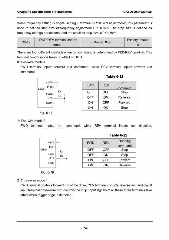
Chapter 6 Specification of Parameters GK600 User Manual
- 156 -
When frequency setting is "digital setting + terminal UP/DOWN adjustment", this parameter is used to set the step size of frequency adjustment UP/DOWN. The step size is defined as frequency change per second, and the smallest step size is 0.01 Hz/s.
C0-19 FWD/REV terminal control
mode Range: 0~3
Factory default: 0
There are four different methods when run command is determined by FED/REV terminal. This terminal control mode takes no effect on JOG. 0: Two-wire mode 1
FWD terminal inputs forward run command, while REV terminal inputs reverse run command.
Table 6-11
Fig. 6-17
1: Two-wire mode 2 FWD terminal inputs run command, while REV terminal inputs run direction.
Table 6-12
Fig. 6-18
2: Three-wire mode 1 FWD terminal controls forward run of the drive, REV terminal controls reverse run, and digital input terminal "three-wire run" controls the stop. Input signals of all these three terminals take effect when trigger edge is detected.
FWD REV Run command command OFF OFF Stop
OFF ON Reverse ON OFF Forward ON ON Stop
FWD REV Running command
OFF OFF Stop OFF ON Stop ON OFF Forward ON ON Reverse
+24V
变频器
PLC
FWDREV
COM
K1
K2
+24V
变频器
PLC
FWDREV
COM
K1
K2
Drive
Drive

GK600 User Manual Chapter 6 Specification of Parameters
- 157 -
Fig. 6-19 Three-wire mode 1 SB1 is a stop button, by pressing which the drive will stop; SB2 is a FORWARD button, by pressing which forward run will be activated; SB3 is a REVERSE button, by pressing which reverse run will be activated. Xi is a digital input terminal. In this case, it is necessary to define the function of corresponding terminal as "three-wire run" terminal.
3: Three-wire mode 2 FWD terminal controls the run, while run direction is determined by REV terminal. Digital input terminal "three-wire run" controls the stop.
Fig. 6-20 Three-wire mode 2
SB1 is a stop button, by pressing which the drive will stop; SB2 is a RUN button, by pressing which the drive will run. When switch K is open, run is forward, while when it is closed, run direction is reverse. Xi is a digital input terminal. In this case, it is necessary to define the function of corresponding terminal as "three-wire run" terminal.
C0-20 Option of virtual input
terminal Range: 000~77F
Factory default: 000
This parameter is a 10-bit binary numeral. The terminals that correspond respectively to bit10
+24V
PLC
变频器
FWD
REV
COM
三线式运
行端子Xi
SB3
SB2
SB1
+24V
PLC
变频器
FWD
REV
COM
三线式运行端子Xi
K
SB2
SB1
Drive
Three-wire run
terminal Xi
Three-wire Run
terminal Xi
Drive

Chapter 6 Specification of Parameters GK600 User Manual
- 158 -
(the highest bit of binary system) through bit0 (the lowest bit of binary system) are as follows: Table 6-13
Hundreds place Tens place Ones place
bit10 bit9 bit8 bit7 bit6 bit5 bit4 bit3 bit2 bit1 bit0
EIA AI2 AI1 Revd EX X6 X5 X4 X3 X2 X1
Ones place: bit0~bit3 : X1~X4 0: Actual terminal takes effect 1: Virtual terminal takes effect Tens: bit4~bit6 : X5, X6, EX (same as ones place) Hundreds place: bit8~bit10 : AI1, AI2, EAI (same as ones place) Virtual terminals simulate actual terminals via communication. Each bit represents one terminal. When selecting virtual terminal, corresponding bit should be set to 1 in C0-20. Under this circumstance the actual terminal is invalid.
C0-21 Enabled condition of run command terminal after fault reset (RESET)
Range: 0~1 Factory default:0
This parameter only takes effect on run command terminals, i.e. digital input terminal set as 1~4 (JOG forward/reverse, run forward/reverse. See table 6-6), and only works for the run after fault reset. 0: Trigger edge detected + ON detected
After the fault reset, the drive will start to run when an electric level jump from OFF to ON is detected and ON signal are maintained.
1: ON detected The drive will run automatically if ON signal from run command terminal is detected. When this parameter value is set to 1, please make sure the status of run command terminals before fault reset operation. Failure to comply may result in equipment damage and/or personal injury.
Group C1 Digital Output
C1-00 Y1 output function Range: 0~99 Factory default: 0
C1-01 Y2/DO output function (when used as Y2)
Range: 0~99 Factory default: 0
C1-02 Control board relay output function
Range: 0~99 Factory default: 14
C1-03 Option board relay output function
Range: 0~99 Factory default: 15

GK600 User Manual Chapter 6 Specification of Parameters
- 159 -
Define the functions of digital output terminals Y1 & Y2, control board relay and option board relay. When used as high-speed pulse output, Y2/DO terminal's function are not set in C1-01 but in C3-02. Output terminal function selections are as follows:
Table 6-14
Value Function Value Function
0 No output 17 Drive overheated alarm
1 Drive undervoltage 18 Zero-current detection
2 Drive run preparation completed 19 X1
3 Drive is running 20 X2
4 Drive running at 0Hz (no output at
stop) 21 Motor 1/2 indication
5 Drive running at 0Hz (output at stop) 22 Set count value attained
6 Run direction 23 Designated count value attained
7 Frequency attained 24 Length attained
8 Upper limit frequency attained 25 Consecutive run time attained
9 Lower limit frequency attained 26 Accumulative run time attained
10 Frequency detection FDT1 27 Brake control
11 Frequency detection FDT2 28~29 Reserved
12 Reserved 30 PLC step completed
13 Torque restricted 31 PLC cycle completed
14 Fault output 32 Wobble frequency attains to upper
or lower limit frequency
15 Alarm output 33 Frequency attains to upper/lower limit frequency
16 Drive (motor) overloaded alarm 34 Frequency attains target-frequency set by C2-29
0: No output Output terminal is disabled, and there is no output.
1: Drive undervoltage When DC bus voltage is lower than the level of undervoltage, it outputs ON signal and LED control panel displays "LoU".

Chapter 6 Specification of Parameters GK600 User Manual
- 160 -
2: Drive run preparation completed The output of ON signal indicates that the drive is free of fault. Under this circumstance, the drive is ready to accept run command.
3: Drive is running The output is ON when the drive is running, and output is OFF when drive stopped.
4: Drive running at 0Hz (no output at stop) When running at 0Hz, this corresponding terminal outputs ON signal. No ON signal will be output at stop.
5: Drive running at 0Hz (output at stop) Outputs ON signal when running at 0Hz, and also outputs ON signal at stop.
6: Run direction Outputs OFF signal under forward run and outputs ON signal under reverse run.
7: Frequency attained When the deviation of output frequency from set frequency is less than the value of C1-14 (Detective width of frequency attained), outputs ON.
8: Upper limit frequency attained When output frequency attains b0-09 (upper limit frequency), outputs ON.
9: Lower limit frequency attained When output frequency attains b0-10 (lower limit frequency), outputs ON.
10: Frequency detection FDT1 Terminal outputs ON signal when output frequency exceeds C1-10 (FDT1 upper bound) and will not output OFF signal unless output frequency drops to below C1-11 (FDT1 lower bound).
11: Frequency detection FDT2 Terminal outputs ON when output frequency exceeds C1-12 (FDT2 upper bound) and will not output OFF unless output frequency drops to below C1-13 (FDT2 lower bound).
12: Reserved 13: Torque restricted
This takes effect only in the mode of sensor-less vector control. If output torque attains the limit value of drive torque or brake torque, terminal outputs ON.
14: Fault output When the drive is in fault, it outputs ON.
15: Alarm output When inverter gives an alarm, ON signal is output.
16: Drive (motor) overloaded alarm In case drive output current exceeds E1-04 (overload alarm threshold ) and its last time exceeds E1-05 (overload alarm activated time that exceeding threshold), outputs ON. Refer to parameters E1-03~E1-05 for information with regard to drive (motor) overloaded alarm.
ATTENTION:
In case of either drive is overloaded or motor is overloaded, it also will output ON.

GK600 User Manual Chapter 6 Specification of Parameters
- 161 -
17: Drive overheat alarm When drive internally detected temperature exceeds E1-13 (Drive overheat alarm threshold), ON signal will be output.
18: Zero-current detection When drive output current is less than the value of C1-15 (effective proportion of zero current detected) and the lasting time attains the value of C1-16 (Zero current detected time), ON signal will be output.
19: X1 Output the status of X1.
20: X2 Output the status of X2.
21: Motor 1/2 indication When motor 1 is selected, outputs OFF. When motor 2 is selected, outputs ON.
22: Set count value attained Refer to the specification of parameter F3-12.
23: Designated count value attained Refer to the specification of parameter F3-13.
24: Length attained Refer to the specification of parameters F3-08~F3-11.
25: Consecutive run time attained When consecutive run time attains the value of E0-03, corresponding terminal outputs ON. Consecutive run time is cleared when stop.
26: Accumulative run time attained When accumulative run time attains the value of E0-04, corresponding terminal outputs ON. Accumulative run time is maintained when stop.
27: Brake control Refer to the specification of parameters E0-05~E0-11 for details.
28: Reserved 29: Reserved 30: PLC step completed
Upon the completion of current step of simple PLC running, ON signal with the width of 500ms will be output.
31: PLC cycle completed Upon the completion of a cycle of simple PLC running, ON signal with a width of 500ms will be output.
32: Wobble frequency attains to upper or lower limit frequency When drive output frequency attains upper limit frequency b0-09 or lower limit frequency b0-10 under wobble frequency running, ON signal will be output.
33: Upper/lower limit of set FREQ attained 34: Target FREQ attained (set by C2-29)
When the error of drive output frequency and C2-29 value is less than C1-14, target
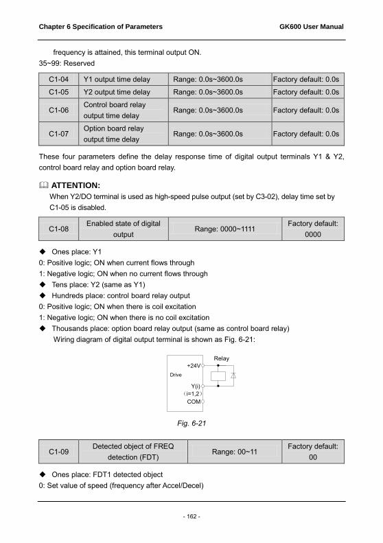
Chapter 6 Specification of Parameters GK600 User Manual
- 162 -
frequency is attained, this terminal output ON. 35~99: Reserved
C1-04 Y1 output time delay Range: 0.0s~3600.0s Factory default: 0.0s
C1-05 Y2 output time delay Range: 0.0s~3600.0s Factory default: 0.0s
C1-06 Control board relay output time delay
Range: 0.0s~3600.0s Factory default: 0.0s
C1-07 Option board relay output time delay
Range: 0.0s~3600.0s Factory default: 0.0s
These four parameters define the delay response time of digital output terminals Y1 & Y2, control board relay and option board relay.
ATTENTION: When Y2/DO terminal is used as high-speed pulse output (set by C3-02), delay time set by C1-05 is disabled.
C1-08 Enabled state of digital
output Range: 0000~1111
Factory default: 0000
Ones place: Y1 0: Positive logic; ON when current flows through 1: Negative logic; ON when no current flows through Tens place: Y2 (same as Y1) Hundreds place: control board relay output 0: Positive logic; ON when there is coil excitation 1: Negative logic; ON when there is no coil excitation Thousands place: option board relay output (same as control board relay)
Wiring diagram of digital output terminal is shown as Fig. 6-21:
Fig. 6-21
C1-09 Detected object of FREQ
detection (FDT) Range: 00~11
Factory default: 00
Ones place: FDT1 detected object 0: Set value of speed (frequency after Accel/Decel)
+24V
变频器
COM(i=1,2)
Y(i)
继电器
Drive Relay
GK600 User Manual Chapter 6 Specification of Parameters
- 163 -
FDT1 output frequency is the set frequency after Accel/Decel. 1: Detected speed value
FDT1 output frequency is actually detected or identified frequency. If the drive is under V/f pattern, it should be output frequency.
Tens place: FDT2 detected object0: Set value of speed (frequency after Accel/Decel)
FDT2 output frequency is the set frequency after Accel/Decel. 1: Detected speed value
FDT2 output frequency is actually detected or identified frequency. If the drive is under V/f pattern, it should be output frequency.
C1-10 FDT1 upper value Range: 0.00Hz~maximum FREQ Factory default: 50.00Hz
C1-11 FDT1 lower value Range: 0.00Hz~ maximum FREQ Factory default: 49.00Hz
C1-12 FDT2 upper value Range: 0.00Hz~ maximum FREQ Factory default: 25.00Hz
C1-13 FDT2 lower value Range: 0.00Hz~ maximum FREQ Factory default: 24.00Hz
These parameters should be set with digital output terminals "FDT1" and "FDT2". Take FDT1 for example, the drive outputs ON signal when output frequency exceeds upper value of FDT1 and will not output OFF signal unless output frequency drops to below lower value of FDT1. Please set C1-10 to be larger to some certain extent than C1-11, avoiding status change frequently. See Fig. 6-22:
FDT2 performance figure is the same as FDT1.

Chapter 6 Specification of Parameters GK600 User Manual
- 164 -
Fig. 6-22
C1-14 Detection width of frequency attained
Range: 0.00Hz~ maximum FREQ
Factory default: 2.50Hz
This parameter should be set with digital output terminal "frequency attained". When the difference between output frequency and set frequency is less than this value, terminal "frequency attained" outputs ON. See Fig. 6-23:
Fig. 6-23
时间
输出频率
时间
FDT1电平下限
FDT1电平上限
FDT1端子
时间
输出
时间
频率到达端子
设定频率频率检出宽度
Output frequency
FDT1 upper value FDT1 lower value
FDT1 terminal
Time
Time
Output
Set frequency Frequency detection width
Time
Frequency attained terminal
Time

GK600 User Manual Chapter 6 Specification of Parameters
- 165 -
C1-15 Zero current detection
value Range: 0.0%~50.0%
Factory default: 5.0%
C1-16 Zero current detection time Range: 0.01s~50.00s Factory default:
0.50s
The two parameters should be set with digital output terminal "zero current detection". When the drive output current is less than the value set by C1-15 and its lasting time attains the value of C1-16, terminal "zero current detection" outputs ON signal. See Fig. 6-24:
Fig. 6-24
Group C2 Analog and Pulse Input
C2-00 Analog input curve Range: 000~222 Factory default: 000
Curves of analog input AI1, AI2 and EAI are selected by this parameter. Ones place: AI1 input curve 0: Curve 1 (2 points)
Defined by C2-01~C2-04. 1: Curve 2 (4 points)
Defined by C2-05~C2-12. 2: Curve 3 (4 points)
Defined by C2-13~C2-20. 3: Curve 2 and curve 3 switchover
Curve 2 and curve 3 selection can be switched via terminal “analog input curve switchover”. When this terminal is deactivated, curve 2 takes effect, while when this terminal is activated, curve 3 will work.
时间
输出电流
时间
零电流检测端子
零电流检出水平
零电流检出时间
运行 停机
Output current
Run Stop
Zero current detection value Time
Zero current detection terminal Zero
current detection
time
Time

Chapter 6 Specification of Parameters GK600 User Manual
- 166 -
Tens place: AI2 input curve Same as specification of AI1.
Hundreds place: EAI input curve Same as specification of AI1.
Thousands place: reserved
C2-01 Curve 1 maximum input Range: minimum input of curve 1 ~110.0%
Factory default: 100.0%
C2-02 Corresponding set value of curve 1 maximum input
Range: -100.0%~100.0% Factory default: 100.0%
C2-03 Curve 1 minimum input Range: -110.0% ~ curve 1 maximum input
Factory default: 0.0%
C2-04 Corresponding set value of curve 1 minimum input
Range: -100.0%~100.0% Factory default: 0.0%
Curve 1 is defined by above-noted 4 parameters. Input values C2-01 and C2-03: EAI on option board and AI1 can select 0~10V voltage input or 0~20mA current input by jumper. If 0~10V is selected: 0V corresponds to 0%, while 10V corresponds to 100%. If 0~20mA is selected: 0mA corresponds to 0%, while 20mA corresponds to 100%. AI2 only supports -10V~10V input; for AI2, -10V corresponds to -100%, while 10V corresponds to 100%.
Corresponding set values C2-02 and C2-04: When the corresponding set value is frequency: 100% is the maximum frequency, while -100% is the maximum negative frequency. When the corresponding set value is current: 100% means 2 times the rated current of drive while "less than or equal to 0%" corresponds to zero current. When corresponding set value is torque: 100% means 2 times the rated torque, while -100% means minus "2 times the rated torque". When the corresponding set value is output voltage (e.g. the voltage setting in case of V/f separated pattern): 100% corresponds to rated voltage of motor. "Less than or equal to 0%" corresponds to 0V voltage.
Curve diagram is shown as below:

GK600 User Manual Chapter 6 Specification of Parameters
- 167 -
Fig. 6-25 Fig. 6-26
Fig. 6-27 Fig. 6-28
C2-05 Curve 2 maximum input Range: input of curve 2 inflection point A~110.0%
Factory default: 100.0%
C2-06 Set value corresponding to
curve 2 maximum input Range: -100.0%~100.0%
Factory default: 100.0%
C2-07 Input of curve 2 inflection point
A
Input of curve 2 inflection point B ~ curve 2 maximum input
Factory default: 0.0%
C2-08
Set value corresponding to
input of curve 2 inflection point
A
Range: -100.0%~100.0% Factory default: 0.0%
对应设定值
AI模拟量曲线1最大输入
(C2-01)曲线1最小输入
(C2-03)
曲线1最大输入
对应设定值
(C2-02)
曲线1最小输入
对应设定值
(C2-04)
对应设定值
AI模拟量曲线1最大输入
(C2-01)曲线1最小输入
(C2-03)
曲线1最小输入 对应设定值
(C2-04)
曲线1最大输入
对应设定值
(C2-02)
AI模拟量
对应设定值
曲线1最大输入
(C2-01)
曲线1最小输入
(C2-03)
曲线1最小输入 对应设定值
(C2-04)
曲线1最大输入
对应设定值 (C2-02)
对应设定值
AI模拟量曲线1最大输入
(C2-01)
曲线1最小输入
(C2-03)
曲线1最大输入
对应设定值
(C2-02)
曲线1最小输入
对应设定值
(C2-04)
Corresponding set value
Set value that corresponds to curve 1 maximum input (C2-02)
Set value that corresponds to curve 1 minimum input (C2-04)
Curve 1 minimum input (C2-03)
Curve 1 maximum input (C2-01)
AI analog
Corresponding set value
Set value that corresponds to curve 1 maximum input (C2-02)
Set value that corresponds to curve 1 minimum input (C2-04)
Curve 1 minimum input (C2-03)
Curve 1 maximum input (C2-01)
AI analog
Corresponding set value Corresponding set value
Set value that corresponds to curve 1 minimum input (C2-04)
Set value that corresponds to curve 1 maximum input (C2-02)
Set value that corresponds to curve 1 minimum input (C2-04)
Set value that corresponds to curve 1 maximum input (C2-02)
Curve 1 minimum input (C2-03)
Curve 1 maximum input (C2-01)
AI analog
Curve 1 maximum input (C2-01)
Curve 1 minimum input (C2-03)
AI analog
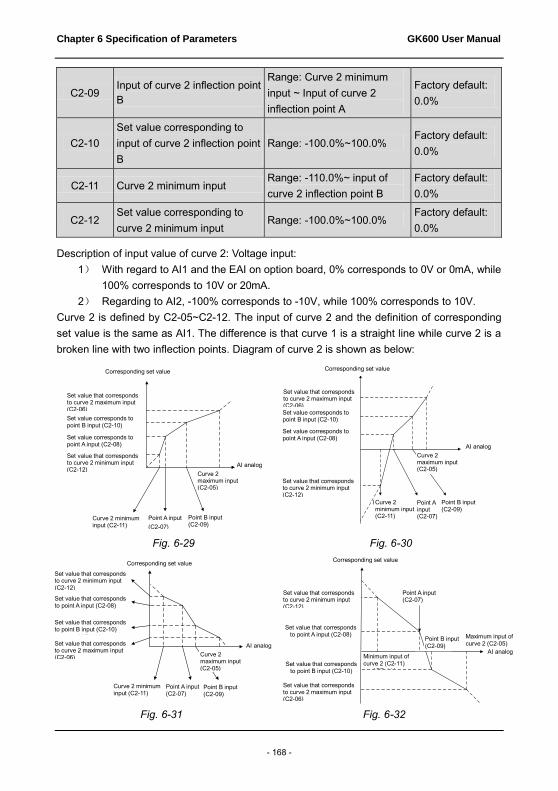
Chapter 6 Specification of Parameters GK600 User Manual
- 168 -
C2-09 Input of curve 2 inflection point B
Range: Curve 2 minimum input ~ Input of curve 2 inflection point A
Factory default: 0.0%
C2-10 Set value corresponding to input of curve 2 inflection point B
Range: -100.0%~100.0% Factory default: 0.0%
C2-11 Curve 2 minimum input Range: -110.0%~ input of curve 2 inflection point B
Factory default: 0.0%
C2-12 Set value corresponding to curve 2 minimum input
Range: -100.0%~100.0% Factory default: 0.0%
Description of input value of curve 2: Voltage input:
1) With regard to AI1 and the EAI on option board, 0% corresponds to 0V or 0mA, while 100% corresponds to 10V or 20mA.
2) Regarding to AI2, -100% corresponds to -10V, while 100% corresponds to 10V. Curve 2 is defined by C2-05~C2-12. The input of curve 2 and the definition of corresponding set value is the same as AI1. The difference is that curve 1 is a straight line while curve 2 is a broken line with two inflection points. Diagram of curve 2 is shown as below:
Fig. 6-29 Fig. 6-30
Fig. 6-31 Fig. 6-32
对应设定值
AI模拟量曲线2最大输入
(C2-05)
曲线2最小输入
(C2-11)
曲线2最大输入对应
设定值(C2-06)
曲线2最小输入对应 设定值(C2-12)
A点输入
(C2-07)B点输入
(C2-09)
A点输入对应
设定值(C2-08)
B点输入对应
设定值(C2-10)
对应设定值
AI模拟量曲线2最大输入
(C2-05)
曲线2最小输入
(C2-11)
曲线2最小输入对应
设定值(C2-12)
曲线2最大输入对应
设定值(C2-06)
A点输入
(C2-07)B点输入
(C2-09)
A点输入对应设定值
(C2-08)
B点输入对应设定值
(C2-10)
对应设定值
AI模拟量
曲线2最大输入
(C2-05)曲线2最小输入
(C2-11)
曲线2最小输入对应
设定值(C2-12)
曲线2最大输入对应
设定值(C2-06)
A点输入
(C2-07)
B点输入
(C2-09)
A点输入对应的
设定值(C2-08)
B点输入对应的
设定值(C2-10)
对应设定值
AI模拟量曲线2最大输入
(C2-05)
曲线2最小输入
(C2-11)
曲线2最大输入对应
设定值(C2-06)
曲线2最小输入对应
设定值(C2-12)
A点输入
(C2-07)B点输入
(C2-09)
A点输入对应
设定值(C2-08)
B点输入对应
设定值(C2-10)
Corresponding set value Corresponding set value
Set value that corresponds to curve 2 maximum input (C2-06) Set value corresponds to point B input (C2-10) Set value corresponds to point A input (C2-08) Set value that corresponds to curve 2 minimum input (C2-12)
Curve 2 minimum input (C2-11)
Point A input (C2-07)
Point B input (C2-09)
Set value that corresponds to curve 2 maximum input (C2-06) Set value corresponds to point B input (C2-10) Set value corresponds to point A input (C2-08)
Curve 2 maximum input (C2-05)
AI analog Set value that corresponds to curve 2 minimum input (C2-12)
Curve 2 maximum input (C2-05)
AI analog
Curve 2 minimum input (C2-11)
Point A input (C2-07)
Point B input (C2-09)
Corresponding set value Corresponding set value
Set value that corresponds to curve 2 minimum input (C2-12) Set value that corresponds to point A input (C2-08)
Set value that corresponds to point B input (C2-10)
Set value that corresponds to curve 2 maximum input (C2-06)
Curve 2 minimum input (C2-11)
Point A input (C2-07) Point B input
(C2-09)
Curve 2 maximum input (C2-05)
AI analog
Set value that corresponds to curve 2 minimum input (C2-12)
Set value that corresponds to point A input (C2-08)
Set value that corresponds to point B input (C2-10)
Set value that corresponds to curve 2 maximum input (C2-06)
Point A input (C2-07)
Point B input (C2-09)
Maximum input of curve 2 (C2-05)
AI analog Minimum input of curve 2 (C2-11)
GK600 User Manual Chapter 6 Specification of Parameters
- 169 -
C2-13 Curve 3 maximum input Range: input of curve 3 inflection point A ~110.0%
Factory default: 100.0%
C2-14 Set value corresponding to curve 3 maximum input
Range: -100.0%~100.0% Factory default: 100.0%
C2-15 Input of curve 3 inflection point A
Range: input of curve 3 inflection point B ~ curve 3 maximum input
Factory default: 0.0%
C2-16 Set value corresponding to input of curve 3 inflection point A
Range: -100.0%~100.0% Factory default: 0.0%
C2-17 Input of curve 3 inflection point B
Range: curve 3 minimum input~ input of curve 3 inflection point A
Factory default: 0.0%
C2-18 Set value corresponding to input of curve 3 inflection point B
Range: -100.0%~100.0% Factory default: 0.0%
C2-19 Curve 3 minimum input Range: -110.0%~ input of curve 3 inflection point B
Factory default: 0.0%
C2-20 Set value corresponding to curve 3 minimum input
Range: -100.0%~100.0% Factory default: 0.0%
Curve 3 is defined by C2-13~C2-20. The usage of curve 3 is the same as that of curve 2.
C2-21 AI1 terminal filtering time Range: 0.000s~10.000s Factory default: 0.1s
C2-22 AI2 terminal filtering time Range: 0.000s~10.000s Factory default: 0.1s
C2-23 EAI terminal filtering time Range: 0.000s~10.000s Factory default: 0.1s
C2-21~C2-23 define the filtering time of analog input terminals AI1, AI2 and EAI. Long filtering time results in strong immunity from interference but slow response, while short filtering time brings rapid response but weak immunity from interference.
C2-24 DI maximum input Range: C2-26~50.0kHz Factory default: 50.0kHz
C2-25 Set value corresponding to DI maximum input
Range: -100.0%~100.0% Factory default: 100.0%
C2-26 DI minimum input Range: 0.0kHz~C2-24 Factory default: 0.0kHz
C2-27 Set value corresponding to DI minimum input
Range: -100.0%~100.0% Factory default: 0.0%
When digital input terminal X6/DI receives pulse signal as frequency setting, the relation

Chapter 6 Specification of Parameters GK600 User Manual
- 170 -
between input pulse signal and frequency setting is defined by curves set by C2-24~C2-27.
C2-24 and C2-26 represent the range of DI input pulse frequency. C2-25 and C2-27 are the set values of frequency that corresponds to DI input pulse frequency: 100% corresponds to positive maximum frequency while -100% corresponds to negative maximum frequency.
ATTENTION: When pulse input is selected as the frequency setting, X6/DI terminal shall be set to "pulse input" function (C0-06 is set to 24).
C2-28 DI filtering time Range: 0.000s~1.000s Factory default:
0.001s
Defines the filtering time of terminal X6/DI.
C2-29 Target FREQ Range: 0.00Hz~upper limit
frequency Factory default:
0.0Hz
This parameter should be used together with digital output terminal “Frequency attains target-frequency set by C2-29” (No.34 in table 6-14). When the error between drive output frequency and C2-29 value is less than the value of C1-14, terminal “Frequency attains target-frequency set by C2-29” outputs ON signal.
Group C3 Analog and Pulse Output
C3-00 AO1 output function Range: 0~99 Factory default: 2
C3-01 EAO output function (on IO option board)
Range: 0~99 Factory default: 1
C3-02 Y2/DO output function (when used as DO)
Range: 0~99 Factory default: 0
AO1 and EAO are analog output terminals. When used as high-speed pulse output DO, Y2/DO terminal's functions are set in C3-02.
Voltage output or current output of AO1 and EAO can be selected through jumper switch. When S3 is switched to the position as shown in Fig. 6-33, AO1 output 0~10V. EAO analog output terminal is located at option board.
Fig. 6-33
OFF
ONAI1 AO1485
I
VV
I
S2S1 S3
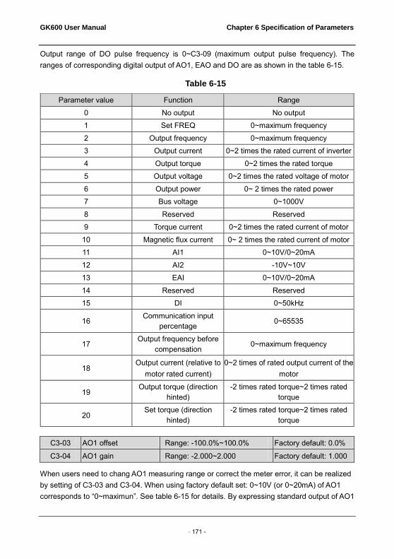
GK600 User Manual Chapter 6 Specification of Parameters
- 171 -
Output range of DO pulse frequency is 0~C3-09 (maximum output pulse frequency). The ranges of corresponding digital output of AO1, EAO and DO are as shown in the table 6-15.
Table 6-15
Parameter value Function Range 0 No output No output 1 Set FREQ 0~maximum frequency 2 Output frequency 0~maximum frequency 3 Output current 0~2 times the rated current of inverter 4 Output torque 0~2 times the rated torque 5 Output voltage 0~2 times the rated voltage of motor 6 Output power 0~ 2 times the rated power 7 Bus voltage 0~1000V 8 Reserved Reserved 9 Torque current 0~2 times the rated current of motor
10 Magnetic flux current 0~ 2 times the rated current of motor 11 AI1 0~10V/0~20mA 12 AI2 -10V~10V 13 EAI 0~10V/0~20mA 14 Reserved Reserved 15 DI 0~50kHz
16 Communication input
percentage 0~65535
17 Output frequency before
compensation 0~maximum frequency
18 Output current (relative to
motor rated current) 0~2 times of rated output current of the
motor
19 Output torque (direction
hinted) -2 times rated torque~2 times rated
torque
20 Set torque (direction
hinted) -2 times rated torque~2 times rated
torque
C3-03 AO1 offset Range: -100.0%~100.0% Factory default: 0.0%
C3-04 AO1 gain Range: -2.000~2.000 Factory default: 1.000
When users need to chang AO1 measuring range or correct the meter error, it can be realized by setting of C3-03 and C3-04. When using factory default set: 0~10V (or 0~20mA) of AO1 corresponds to “0~maximun”. See table 6-15 for details. By expressing standard output of AO1

Chapter 6 Specification of Parameters GK600 User Manual
- 172 -
as x, the adjusted AO1 output as y, the gain as k, and the offset as b (100% of offset corresponds to 10V or 20mA), there is the equation: y=kx+b
Example:
Set C3-00 to 2: output frequency. Standard AO1 output: AO1 outputs 0V when output frequency is 0, and outputs 10V when output frequency is maximum frequency. If AO1 is requested to output 2V when output frequency is 0Hz, and to output 8V when output frequency is the maximum frequency.
There is: 2=k×0+b; 8=k×10+b. Through these two equations, we obtain: k = 0.6, b = 2V, i.e. C3-03 is set to 20.0% while C3-04 is set to 0.600.
Additional examples are shown as below:
Fig. 6-34 Influence of AO1 gain against output
Fig. 6-35 Influence of AO1 offset against output
C3-05 AO1 filtering time Range: 0.0s~10.0s Factory default:
0.0s
Defines output filtering time of AO1 terminal.
C3-06 EAO offset Range: -100.0%~100.0% Factory default:
0.0%
AO1调整后输出
AO1标准输出
10V
0 10V5V
(C3-04) = 100%
(C3-04) = 200%
AO1调整后输出
AO1标准输出
10V
0 10V8.5V
(C3-03) = 0%
(C3-03) = 15%
1.5V
AO1 output after adjustment
AO1 standard output
AO1 output after adjustment
AO1 standard output

GK600 User Manual Chapter 6 Specification of Parameters
- 173 -
C3-07 EAO gain Range: -2.000~2.000 Factory default:
1.000
C3-08 EAO filtering time Range: 0.0s~10.0s Factory default:
0.0s
Adjustment method of EAO output curve is the same as AO1.
C3-09 DO maximum output pulse
frequency Range: 0.1kHz~50.0kHz
Factory default: 50.0kHz
This parameter sets the maximum output frequency when Y2/DO terminal is selected as high-speed pulse output.
C3-10 DO output center point Range: 0~2 Factory default: 0
There are three different center point modes when Y2/DO terminal is selected as high-speed pulse output. 0: No center point.
DO pulse frequency output range 0~ (C3-09) corresponds to "0~maximum", as shown in Fig. 6-36:
Fig. 6-36
1: Center point is (C3-09)/2, and the corresponding parameter value is positive when frequency is higher than center point. The value that corresponds to DO pulse frequency at center point is 0. DO pulse frequency C3-09 corresponds to the positive maximum value, while DO pulse frequency 0Hz corresponds to the negative maximum value. See Fig. 6-37:
DO对应表示量
表示量最大值
0 C3-09DO脉冲频率
DO corresponding value
Maximum corresponding value
DO pulse frequency

Chapter 6 Specification of Parameters GK600 User Manual
- 174 -
Fig. 6-37
2: Center point is (C3-09)/2, and the corresponding parameter value is positive when frequency is lower than center point. The value that corresponds to DO pulse frequency at center point is 0. When set to 0, DO pulse corresponds to the positive maximum value, while when set to C3-09, DO pulse frequency corresponds to the negative maximum value. See Fig. 6-38:
Fig. 6-38
C3-11 DO output filtering time Range: 0.00s~10.00s Factory default:
0.00s
Set the filtering time of DO high-speed pulse output. Filtering can change the changing rate of output pulse frequency. The longer the filtering time is, the lower the change rate of output pulse frequency would be.
DO对应表示量
DO脉冲频率0 C3-09
(C3-09) / 2
表示量正最大值
表示量负最大值
DO对应表示量
DO脉冲频率0
C3-09
(C3-09) / 2
表示量负最大值
表示量正最大值
DO corresponding value
Maximum corresponding value
DO pulse frequency
Maximum negative corresponding value
Do corresponding value
Maximum corresponding value
Maximum negative value of indication value
DO pulse frequency
Maximum negative corresponding value

GK600 User Manual Chapter 6 Specification of Parameters
- 175 -
Group C4 Automatic Correction of Analog Input
Parameter Group C4 is used to perform automatic correction of analog input channels, obtaining the gain and offset of corresponding channel automatically. They can automatically modify the measuring range of corresponding channel or correct meter error.
C4-00 Analog correction Range: 0~3 Factory default: 0
0: No correction
No correction to any analog input. 1: Correct AI1
Automatically correct analog AI1. 2: Correct AI2
Automatically correct analog AI2. 3: Correct EAI
Automatically correct analog EAI.
C4-01 Sampling value of AI1 calibration point 1
Range: 0.00V~10.00V Factory default: 1.00V
C4-02 Input value of AI1 calibration point 1
Range: 0.00V~10.00V Factory default: 1.00V
C4-03 Sampling value of AI1 calibration point 2
Range: 0.00V~10.00V Factory default: 9.00V
C4-04 Input value of AI1 calibration point 2
Range: 0.00V~10.00V Factory default: 9.00V
C4-05 Sampling value of AI2 calibration point 1
Range: -10.00V~10.00V Factory default: 1.00V
C4-06 Input value of AI2 calibration point 1
Range: -10.00V~10.00V Factory default: 1.00V
C4-07 Sampling value of AI2 calibration point 2
Range: -10.00V~10.00V Factory default: 9.00V
C4-08 Input value of AI2 calibration point 2
Range: -10.00V~10.00V Factory default: 9.00V
C4-09 Sampling value of EAI calibration point 1
Range: 0.00V~10.00V Factory default: 1.00V
C4-10 Input value of EAI calibration point 1
Range: 0.00V~10.00V Factory default: 1.00V
C4-11 Sampling value of EAI calibration point 2
Range: 0.00V~10.00V Factory default: 9.00V

Chapter 6 Specification of Parameters GK600 User Manual
- 176 -
C4-12 Input value of EAI calibration point 2
Range: 0.00V~10.00V Factory default: 9.00V
Take AI2 for example, automatic correction is as follows
1) Set C4-00 to 2 in stop status and press ENT key to confirm. In this way, AI2 is selected as correction channel.
2) Input a relatively low analog voltage (e.g. about 1V) via AI2 terminal, and input the theoretical value of this analog voltage by C4-06 after the stabilization of this voltage input, and then press ENT key to confirm.
3) Input a relatively high analog voltage (e.g. about 9V) via AI2 terminal, and input the theoretical value of this analog voltage by C4-08 after the stabilization of this voltage input, and then press ENT key to confirm.
4) Upon the successful correction, C4-00 parameter will be restored to zero.
ATTENTION: Set the theoretical value or actual value of analog voltage in C4-06 and C4-08. This value can be either the set value of analog output of peripheral equipment, or the actual voltage value of analog input measured by a multimeter or other instruments. C4-05 and C4-07 are the sampling values of analog input voltage. These values are for reference only. Do not write the value of C4-05 directly into C4-06, or write the value of C4-07 directly into C4-08.
Group d Motor and Control Parameters
Group d0 Parameters of Motor 1
When motor 1 is selected as current load motor, please set motor parameters in Group d0.
d0-00 Type of motor 1 Range: 0~1 Factory default: 0
0: Ordinary motor 1: Variable frequency motor The major difference between ordinary motor and variable frequency motor lies in the handling of motor overload protection. Under low speed run, ordinary motor has poor heat dissipation, so motor overload protection shall be derated at low speed. Since fan-based heat dissipation of variable frequency motor is not affected by motor speed, low-speed overload protection is not necessarily derated. Therefore, please set d0-00 to 0 when driving ordinary asynchronous motor so as to protect the motor reliably.
d0-01 Power rating of motor 1 Range: 0.4kW~6553.5kW
Factory default: model dependent
d0-02 Rated voltage of motor 1 Range: 0V~480V Factory default: 380V
d0-03 Rated current of motor 1 Range: 0.0A~6553.5A Factory default: model dependent

GK600 User Manual Chapter 6 Specification of Parameters
- 177 -
d0-04 Rated frequency of motor 1 Range: 0.00Hz~upper limit frequency
Factory default: 50.00Hz
d0-05 Pole number of motor 1 Range: 1~80 Factory default: 4
d0-06 Rated speed of motor 1 Range: 0~65535 r/min Factory default: model dependent
Above-noted motor parameters must be correctly set according to motor nameplate. Please select the motor that suits the power class of the drive, or the control performance of the drive will drop dramatically.
d0-07 Stator resistance R1 of motor 1
Range: 0.001Ω~65.535Ω Factory default: model dependent
d0-08 Leakage inductance L1 of motor 1
Range: 0.1mH~6553.5mH Factory default: model dependent
d0-09 Rotor resistance R2 of motor 1
Range: 0.001Ω~65.535Ω Factory default: model dependent
d0-10 Mutual inductance L2 of motor 1
Range: 0.1mH~6553.5mH Factory default: model dependent
d0-11 No-load current of motor 1 Range: 0.0A~6553.5A Factory default: model dependent
d0-12 Flux weakening coeff 1 of motor 1
Range: 0.0000~1.0000 Factory default: model dependent
d0-13 Flux weakening coeff 2 of motor 1
Range: 0.0000~1.0000 Factory default: model dependent
d0-14 Flux weakening coeff 3 of motor 1
Range: 0.0000~1.0000 Factory default: model dependent
The drive needs above-noted parameters to control its matching motor. If the parameters of motor 1 is known, just write the actual value into d0-07~d0-14 correspondingly.
After the autotuning of motor 1, above-noted parameters are automatically updated and saved. Parameters d0-07~d0-09 are obtained through static autotuning, and parameters d0-07~d0-14 are obtained through rotary autotuning. If above-noted parameters are unknown and it is not allowed to perform motor autotuning, please input the parameters manually by referring to parameters of like motors.
If motor power rating d0-01 is changed, d0-02~d0-14 will be automatically restored to default setting of the standard motor.
d0-22 Autotuning of motor 1 Range: 0~2 Factory default: 0
Parameters for controlling the motor performance are automatically obtained through

Chapter 6 Specification of Parameters GK600 User Manual
- 178 -
autotuning, and the result will be automatically saved upon the completion of autotuning. Be sure to correctly input motor 1 parameters d0-01~d0-06 before autotuning. 0: No autotuning 1: Static autotuning
Static autotuning applies to the cases where rotary autotuning cannot be favorably performed due to the fact that it is impossible to disengage the motor from its load. After d0-22 is set to 1 and confirmed, press the key RUN to start static autotuning. d0-22 will be restored to 0 upon the successful completion of autotuning. In this way, parameters d0-07~d0-09 are obtained.
2: Rotary autotuning To perform rotary autotuning, it is essential to disengage the motor from its load. Autotuning is prohibited when motor is loaded. After d0-22 is set to 2 and confirmed, press RUN to perform static autotuning, upon the completion of which, the motor would accelerate to a fixed frequency in the set ramp-up time, maintaining a period of time, and then stop by ramp down according to the set ramp down time. In this way, the autotuning comes to an end, and d0-22 will be restored to 0. Parameters d0-07~d0-14 have be obtained after the successful completion of rotary autotuning. To perform rotary autotuning, please set appropriate ramp-up and ramp-down time (i.e. Accel/Decel time. If overcurrent or overvoltage fault occurs during autotuning, please prolong Accel/Decel time accordingly.
ATTENTION: Please make sure the motor is in a stationary state before the autotuning, or autotuning cannot be performed normally. Control panel displays "TUNE" and RUN indicator light is on during autotuning. RUN indicator light is off upon the completion of autotuning. Once autotuning fails, the fault code "tUN" shall be displayed.
d0-23 Overload protection of
motor 1 Range: 0~2 Factory default: 1
Determine the overload protection of motor 1. 0: No protection
Once 0 is selected, it would be impossible to perform motor overload protection. Please take care.
1: Judged by motor current Provide overload protection judged from output current and its lasting time. Overload protection detection time is set by d0-24.
2: Judged by temperature transducer Input motor temperature sensor signal through analog input channel set by d0-25. The signal voltage is compared with the protection threshold set by d0-26. If it is higher than protection threshold, motor overheat fault "oH2" could be displayed.

GK600 User Manual Chapter 6 Specification of Parameters
- 179 -
d0-24 Overload protection
detection time of motor 1 Range: 0.1min~15.0min
Factory default: 5.0min
When d0-23 is set to "1: judged by motor current", overload protection time is determined by this parameter on the basis of the run current being 150% of motor rated current. An alarm of motor overload fault "oL2" shall be displayed once the lasting time exceeds this parameter value. Protection time when the run current is other value is automatically calculated according to inverse time lag characteristic curve. See Fig. 6-39.
Fig. 6-39 Motor protection curve for ordinary motor running at 50Hz
Overload protection is performed for variable frequency motor according to the curve as shown in Fig. 6-39 at either high or low rotation speed. Due to the fact that fan-based heat dissipation of ordinary motors become poor at low speed, the protection is derated at low speed.
Example: when d0-24 is set to 10.0 minutes, and the motor is running at 10Hz input, motor overload fault "oL2" shall be displayed when the running current is 150% of the motor rated current with lasting time 4 minutes. See Fig. 6-40.
Fig. 6-40 Overload protection curve for ordinary motor running at 10Hz
1
5
10
100% 150% 200%
(d0-24) =10分钟
0
(d0-24) =5分钟
(d0-24) =1分钟
电机电流
电机过载时间
4.0
100% 150% 200%0电机电流
电机过载时间
(d0-24) =10分钟
Motor overload time
(d0-24) = 10 minutes
(d0-24) = 5 minutes
(d0-24) = 1 minutes
Motor current
Motor overload time
(d0-24) = 10 minutes
Motor current

Chapter 6 Specification of Parameters GK600 User Manual
- 180 -
d0-25 Temperature transducer signal
input of motor 1 Range: 0~2 Factory default: 1
0: AI1 1: AI2 2: EAI
When d0-23 is set to "2: judged by temperature transducer ", the analog signal input of temperature sensor of motor 1 is set by this parameter. The drive compares the signal input value via this analog channel with the thermal protection threshold set by d0-26. If it is bigger than the threshold, the drive will immediately give an alarm of motor overheat fault "oH2". Protection through temperature sensor has no characteristic of inverse time lag curve.
d0-26 Thermal protection threshold of motor 1 temperature transducer
Range: 0.00V~10.00V Factory default:
10.00V
This parameter works together with d0-25, and this parameter value, corresponding to motor 1 overheat protection point, needs to be calculated in accordance with the type of temperature sensor. Please consult GTAKE technical service engineer for this parameter value setting. When the input analog signal through the channel selected by d0-25 is bigger than this threshold, the drive will immediately trip with motor overeat fault "oH2".
Group d1 V/f Control Parameters of Motor 1
Set control parameters in Group d1 when motor 1 is selected as current load motor on which V/f control is performed.
d1-00 V/f curve setting Range: 0~8 Factory default: 0
Set the relation between output voltage and output frequency of the drive when motor 1 is under V/f control. 0: Linear V/f
Applies to general constant-torque load. When drive output frequency is 0, output voltage will be 0, while when output frequency is rated frequency of motor, the output voltage would be rated voltage of motor.
1: Broken line V/f (determined by d1-01~d1-08) Applies to spin drier, centrifuge, industrial washing machine and other special loads. When drive output frequency is 0, output voltage will be 0, while when output frequency is rated frequency of motor, the output voltage would be rated voltage of motor. What is different is this pattern can set 4 inflection points by d1-01~d1-08. See Fig. 6-41.

GK600 User Manual Chapter 6 Specification of Parameters
- 181 -
Fig. 6-41 User-defined various segments V/f curve
V0, V1, V2, V3 and f0, f1, f2 and f3 in the figure are voltage value and frequency value set by parameters d1-01~d1-08.
2: 1.2nd power 3: 1.4th power 4: 1.6th power 5: 1.8th power 6: 2.0th power
Parameter values 2~6 apply to torque-dropped loads such as fans and water pumps. See Fig. 6-42.
Fig. 6-42 1.2~2.0 power V/f curve
输出电压(V)
输出频率(Hz)f00 f1 f2 f3 电机额定频率
V0
V1
V2
V3
电机额定电压
0输出频率(Hz)
输出电压(V)
直线V/f
1.2次幂
1.4次幂
1.6次幂
1.8次幂
2.0次幂
电机额定电压
电机额定频率
Output voltage (V)
Rated voltage of motor
Output frequency (Hz) Rated frequency of motor
Output voltage (V) power
Rated voltage of motor
SL V/f
Rated frequency of motor
Output frequency (Hz)
power power
power power

Chapter 6 Specification of Parameters GK600 User Manual
- 182 -
7: V/f separated pattern 1 Output frequency and output voltage can be set separately. Frequency is set by the method as stated in Group b0. Output voltage is set by d1-18. See d1-18 for details. This mode applies to variable-frequency power supply or torque motor control etc.
8: V/f separated pattern 2 Determine a certain voltage by linear V/f mode, and then multiply this voltage by the proportion set by d1-18 to obtain drive output voltage. See d1-18 for details.
d1-01 V/f frequency value f3 Range: 0.00Hz~rated frequency
of motor Factory default: 50.00Hz
d1-02 V/f voltage value V3 Range: 0.0%~100.0% Factory default: 100.0%
d1-03 V/f frequency value f2 Range: d1-05~d1-01 Factory default: 0.00Hz
d1-04 V/f voltage value V2 Range: 0.0%~100.0% Factory default: 0.0%
d1-05 V/f frequency value f1 Range: d1-07~d1-03 Factory default: 0.00Hz
d1-06 V/f voltage value V1 Range: 0.0%~100.0% Factory default: 0.0%
d1-07 V/f frequency value f0 Range: 0.00Hz~d1-05 Factory default: 0.00Hz
d1-08 V/f voltage value V0 Range: 0.0%~100.0% Factory default: 0.0%
d1-01~d1-08 is used for broken line V/f mode. Voltage value 100% corresponds to rated voltage of motor. Please suitably set the values of frequency and voltage at knees on the basis of characteristics of motor and load. Improper setting may rise output current even burn the motor.
d1-09 Torque boost Range: 0.0%~30.0% Factory default:
0.0%
Under V/f pattern, output voltage at low frequency can be compensated by this parameter, improving the torque output. 0.0% corresponds to automatic torque boost, and drive output voltage is automatically compensated via detection of load current. Automatic torque boost is valid only for linear V/f pattern.
100% of torque boost corresponds to rated voltage of motor. A non-zero value means the output voltage rises on the basis of V/f curve and this takes effect at parameter values 0~6 of d1-00. It is suggested this parameter value be gradually increased from zero until the starting requirement is met. Boost value is not suggested to be set to a relatively big one, as it is likely

GK600 User Manual Chapter 6 Specification of Parameters
- 183 -
to bring about a bigger drive current and higher motor temperature.
Torque boost diagram is shown as Fig. 6-43:
Fig. 6-43
d1-10 Slip compensation gain Range: 0.0%~400.0% Factory default:
100.0%
Used under V/f control. When the motor is driving an electric-driven load, motor speed drops with the increase of load. When the motor is driving a power generating load, motor speed will increase with the increase of load. Appropriate slip compensation gain can maintain constant motor speed when the motor load is changing.
To ensure the performance of slip compensation gain, setting motor rated speed d0-06 is essential. The difference between d0-06 and the motor running speed without load is the rated slip. Through real-time detection of motor load, slip compensation automatically adjusts the drive output frequency on the basis of rated slip and motor load, reducing the impact of changing load on motor speed.
Gain adjustment method: please make the adjustment around 100%. When motor is driving an electric-driven load: if motor speed is relatively lower, the gain should be appropriately increased; if motor speed is relatively higher, reduce the gain appropriately. When motor is driving a power generating load: if motor speed is relatively lower, the gain should be decreased; if motor speed is relatively higher, increase the gain appropriately.
Diagram of slip compensation gain is shown as Fig. 6-44 and 6-45.
0输出频率(Hz)
输出电压(V)
电机额定频率
电机额定电压
提升量
Output frequency (Hz)
Output voltage (V)
Rated voltage of motor
Boost value
Rated frequency of motor

Chapter 6 Specification of Parameters GK600 User Manual
- 184 -
Fig. 6-44 Diagram of slip compensation on electric driven load
Fig. 6-45 Diagram of slip compensation on power generating load
d1-11 Droop control Range: 0.00Hz~maximum
frequency Factory default:
0.00Hz
In case several drives drive one load, different drives may bear different proportion of the load. Through the setting of this parameter, the uniform load distribution on these drives could be attained.
The drive takes real-time detection of its load. Output frequency is automatically dropped according to the load and this parameter value, reducing itself borne load proportion. Parameter value of d1-11 corresponds to drop frequency with rated load.
0 电机负载
电机转速
额定负载
n1 = 电机额定转速
n3 = 电机额定转速-额定转差
n2 = 电机额定转速-额定转差/2
n1
n2
n3
转差补偿增益 (d1-10)=100%
转差补偿增益 (d1-10)=50%
转差补偿增益 (d1-10)=0%
0电机负载
电机转速
额定负载
n1 = 电机额定转速
n3 = 电机额定转速+额定转差
n2 = 电机额定转速+额定转差/2
n1
n2
n3
转差补偿增益 (d1-10)=100%
转差补偿增益 (d1-10)=0%
转差补偿增益 (d1-10)=50%
Motor speed Slip compensation gain (d1-10) = 100%
Slip compensation gain (d1-10) = 50%
Slip compensation gain (d1-10) = 0%
n1 = rated speed of motor n2 = rated motor speed - rated slip/2 n3 = rated motor speed - rated slip
Rated load Motor load
Slip compensation gain (d1-10) = 0% Motor speed
n3 = rated motor speed + rated slip n2 = rated motor speed + rated slip/2 n1 = rated motor speed
Slip compensation gain (d1-10) = 100%
Slip compensation gain (d1-10) = 50%
Rated load
Motor load

GK600 User Manual Chapter 6 Specification of Parameters
- 185 -
d1-12 Current limitation mode Range: 0~5 Factory default: 1
0: Disabled 1: Set by d1-13 2: Set by AI1 3: Set by AI2 4: Set by EAI Drive output current is limited by analog input in the range of " 0~200% x rated current of drive". 5: Set by X6/DI Drive output current is limited by X6/DI pulse input in the range of "0~200% x rated current of drive".
When a non-zero value is set by d1-12, the current limitation is enabled. When output current rises dramatically because of sharp change of load, instant adjustment of output frequency will keep the output frequency below the set limitation. When the load is reduced, output frequency will recover promptly. If the setting speed or motor load change dramatically, this function can effectively reduce over-current fault.
When current limitation is enabled, the output frequency at constant speed may change at times and the Accel/Decel time may probably be automatically prolonged. Therefore, this function should not be used where output frequency or Accel/Decel time is not allowed to change.
d1-13 Digital setting of current
limit value Range: 20.0%~200.0%
Factory default: 160.0%
When d1-12 is set to "1: set by d1-13", the drive keeps output current less than this current limit value through instantaneous adjustment of output frequency. 100% current limit value corresponds to rated current of the drive. If this parameter value is set to a relatively big one, it will increase the chances of over-current. If this parameter value is set to a relatively small one, it will affect the loaded capability of the drive.
d1-14 Current limit coeff on flux
weakening Range: 0.001~1.000
Factory default: 0.500
When the drive runs at the frequency higher than rated frequency of motor, Accel/Decel characteristic and output torque can be effectively improved by setting this parameter appropriately.
d1-15 Energy saving percentage Range: 0%~40.0% Factory default:
0.0%
During no-load or light-load application, load current is detected so as to appropriately reduce output voltage, reducing the copper loss and iron loss of motor with the purpose of energy saving. The larger the energy-saving percentage is, the better the energy-saving effect will be,

Chapter 6 Specification of Parameters GK600 User Manual
- 186 -
but the response will be slower. This parameter is applicable to loads such as fan and pump or light-load for a long time. Where rapid change is required, this parameter is suggested to be default set 0.0%.
d1-16 V/f oscillation suppression
gain 1 Range: 0~3000
Factory default: 38
d1-17 V/f oscillation suppression
gain 2 Range: 0~3000 Factory default: 0
Under V/f control, speed and current oscillation is likely to occur due to load vibration, and may lead to system failure even over current protection. This is particularly obvious during no-load or light-load applications. The appropriate setting of parameter values of d1-16 and d1-17 would effectively suppress speed and current oscillation. In many case it is not necessary to modify the default setting. Please make progressive change around default setting, since excessive setting will influence V/f control performance.
d1-18 Voltage setting on V/f
separated pattern Range: 0~5 Factory default: 0
This parameter takes effect when d1-00 is set to 7 or 8. 0: d1-19 digital setting
Under V/f separated pattern 1, drive output voltage is completely determined by d1-19. 100% corresponds to motor rated voltage. Under V/f separated pattern 2, output voltage = voltage calculated according to linear V/f curve x 2 x d1-19.
1: Set by AI1 2: Set by AI2 3: Set by EAI
Under V/f separated pattern 1, drive output voltage is completely determined by the selected analog. The biggest setting is the motor rated voltage. Under V/f separated pattern 2, output voltage = voltage calculated according to linear V/f curve x the proportion determined by the analog input. The maximum set value can be 200%.
4: Process PID output Outputs voltage on the basis of process PID. Under V/f separated pattern 1, output voltage is determined by the output of process PID. Under V/f separated pattern 2, the output of process PID is a proportional value whose maximum set value could be 200%. Then this proportional value is multiplied by the voltage calculated according to linear V/f curve to obtain drive output voltage. Refer to parameter group F0 for information of process PID.
5: AI1 + process PID output Under V/f separated pattern 1, drive output voltage is determined by "AI1 + process PID

GK600 User Manual Chapter 6 Specification of Parameters
- 187 -
output". The maximum set value of AI1 is motor rated voltage.
Under V/f separated pattern 2, "AI1 + process PID" output is a proportional value whose maximum set value corresponds to 200%. This proportional value is multiplied by the voltage calculated according to linear V/f to obtain drive output voltage.
d1-19 Digital set voltage on V/f
separated pattern Range: 0.0%~100.0%
Factory default: 0.0%
When 0 is selected at d1-18, the output voltage will be determined by d1-19.
d1-20 Voltage variation time on
V/f separated pattern Range: 0.00s~600.00s
Factory default: 0.01s
Sets the output voltage change rate under V/f separation pattern. This parameter value is the time rising from 0V to motor rated voltage or dropping from rated voltage to 0V.
Group d2 Vector Control Parameters of Motor 1
Set control parameters in Group d2 when motor 1 is selected as current load motor on which sensor-less vector control is performed.
d2-00 Reserved Reserved Reserved
d2-01 ASR high-speed proportional gain Kp1
Range: 0.0~20.0 Factory default: 2.0
d2-02 ASR high-speed integration time Ti1
Range: 0.000s~8.000s Factory default: 0.200
d2-03 ASR low-speed proportional gain Kp2
Range: 0.0~20.0 Factory default: 2.0
d2-04 ASR low-speed integration time Ti2
Range: 0.000s~8.000s Factory default: 0.200
d2-05 ASR switching frequency 1 Range: 0.00Hz~d2-06 Factory default: 5.00Hz
d2-06 ASR switching frequency 2 Range: d2-05~upper limiting frequency
Factory default: 10.00Hz
Under sensor-less vector control (SVC), motor speed is kept at set value by automatic speed regulator (ASR). ASR parameters should be set in d2-01~d2-06.
The proportional gain Kp and integration time Ti of ASR can be set through d2-01~d2-04 so as to change the speed response characteristic under SVC. Increment of proportional gain Kp can bring in fast response of the system. However, bigger Kp value will bring about larger system oscillation.
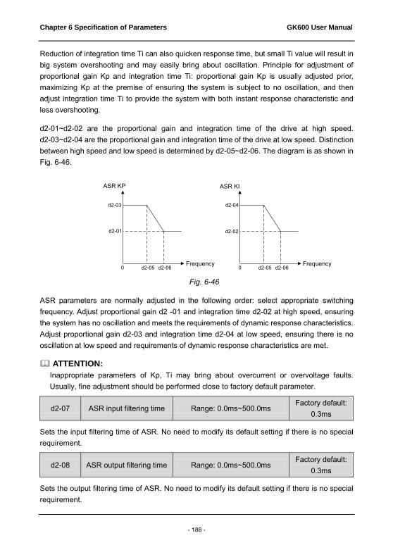
Chapter 6 Specification of Parameters GK600 User Manual
- 188 -
Reduction of integration time Ti can also quicken response time, but small Ti value will result in big system overshooting and may easily bring about oscillation. Principle for adjustment of proportional gain Kp and integration time Ti: proportional gain Kp is usually adjusted prior, maximizing Kp at the premise of ensuring the system is subject to no oscillation, and then adjust integration time Ti to provide the system with both instant response characteristic and less overshooting.
d2-01~d2-02 are the proportional gain and integration time of the drive at high speed. d2-03~d2-04 are the proportional gain and integration time of the drive at low speed. Distinction between high speed and low speed is determined by d2-05~d2-06. The diagram is as shown in Fig. 6-46.
Fig. 6-46
ASR parameters are normally adjusted in the following order: select appropriate switching frequency. Adjust proportional gain d2 -01 and integration time d2-02 at high speed, ensuring the system has no oscillation and meets the requirements of dynamic response characteristics. Adjust proportional gain d2-03 and integration time d2-04 at low speed, ensuring there is no oscillation at low speed and requirements of dynamic response characteristics are met.
ATTENTION: Inappropriate parameters of Kp, Ti may bring about overcurrent or overvoltage faults. Usually, fine adjustment should be performed close to factory default parameter.
d2-07 ASR input filtering time Range: 0.0ms~500.0ms Factory default:
0.3ms
Sets the input filtering time of ASR. No need to modify its default setting if there is no special requirement.
d2-08 ASR output filtering time Range: 0.0ms~500.0ms Factory default:
0.3ms
Sets the output filtering time of ASR. No need to modify its default setting if there is no special requirement.
0频率
速度环KP
d2-03
d2-01
d2-05 d2-06 0
速度环KI
d2-04
d2-02
d2-05 d2-06频率
ASR KP
Frequency
ASR KI
Frequency

GK600 User Manual Chapter 6 Specification of Parameters
- 189 -
d2-09 ACR proportion coefficient
Kp Range: 0.000~4.000
Factory default: 1.000
d2-10 ACR integration coefficient
Ki Range: 0.000~4.000
Factory default: 1.000
These two parameters determine the characteristics of automatic current regulator (ACR) under SVC pattern. Increment of proportion coefficient and/or integration coefficient can shorten torque response time. Reduction of proportion coefficient an/or integration coefficient can increase the stability of the system. Inappropriate setting may bring about system oscillation. Factory default is not needed to be changed in most cases.
d2-11 Pre-excitation time Range: 0.000s~5.000s Factory default:
0.200s
Applies to asynchronous motor. To attain quick start, it is necessary to perform pre-excitation before the running of motor, and the pre-excitation time is set by this parameter. Properly establish stable flux prior and then ramp up quickly. The set value of 0.000s means "no pre-excitation" and ramp up at the moment of the receipt of run command. Pre-excitation time is not included in Accel/Decel time. Factory default is suggested to maintain in most cases.
d2-12 Driven torque restriction
source Range: 0~5 Factory default: 0
Under the pattern of SVC speed control, and when the motor is driving an electric-driven load, it usually needs to restrict the output torque of the motor. This parameter sets the torque restriction source. 0: d2-14 digital setting
Restrict output torque through digital set parameter d2-14. 100% corresponds to motor rated torque.
1: AI1 2: AI2 3: EAI (on IO option board)
Limit the torque through analog input. The limited range is "0~200%r x rated torque". 4: X6/DI pulse input
Restrict the torque through X6/DI pulse input. The limited range is "0~200%r x rated torque". 5: Communication
A superior device sets the restricted value of the output torque through standard RS485 communication interface at the drive. Refer to parameter Group H0 and appendix for details of communication.
d2-13 Braking torque restriction
source Range: 0~5 Factory default: 0
Under the pattern of SVC speed control, and when the motor is driving a power generating load,

Chapter 6 Specification of Parameters GK600 User Manual
- 190 -
it needs to restrict the output brake torque of the motor. This parameter sets the torque restriction source. 0: d2-15 digital setting
Restrict output brake torque through digital set parameter d2-15. 100% corresponds to rated torque of the motor.
1: AI1 2: AI2 3: EAI (on IO option board)
Limit the torque through analog input. The limited range is "0~200%r x rated torque". 4: X6/DI pulse input
Restrict the torque through X6/DI pulse input. The limited range is "0~200%r x rated torque". 5: Communication
A superior device sets the restricted value of the output torque through standard RS485 communication interface at the drive. Refer to parameter Group H0 and appendix for details of communication.
d2-14 Digital setting of driven
torque Range: 0.0%~200.0%
Factory default: 180.0%
When 0 is selected for d2-12, this parameter value limits the maximum output driven torque. 100% corresponds to rated torque of the motor.
d2-15 Digital setting of brake
torque Range: 0.0%~200.0%
Factory default: 180.0%
When d2-13 is set to 0, this parameter value limits the maximum output brake torque. 100% corresponds to rated torque of the motor.
d2-16 Torque limit coefficient in
flux weakening Range: 0.0%~100.0%
Factory default: 50.0%
Under the pattern of SVC speed control, and when the drive is running at frequency higher than rated frequency (flux weakening zone), appropriate torque limit coefficient can effectively improve the performance of output torque and Accel/Decel characteristics.
d2-17 Driven slip compensation
gain Range: 10.0%~300.0%
Factory default: 100.0%
Under SVC pattern, adjustment of this parameter value can improve the speed accuracy when driving electric-driven load. If the load is becoming heavier and the motor speed is relatively lower, set a bigger value, while the motor speed is relatively higher, set a smaller value.
d2-18 Brake slip compensation
gain Range: 10.0%~300.0%
Factory default: 100.0%
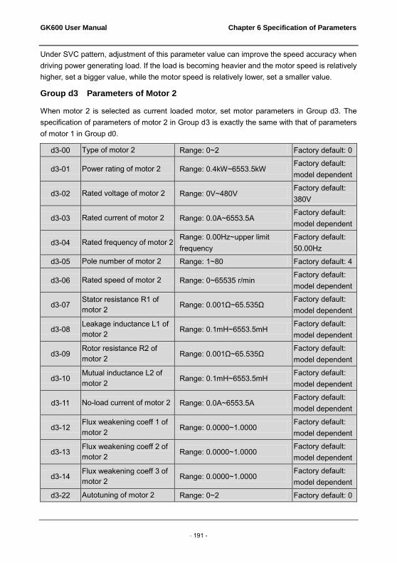
GK600 User Manual Chapter 6 Specification of Parameters
- 191 -
Under SVC pattern, adjustment of this parameter value can improve the speed accuracy when driving power generating load. If the load is becoming heavier and the motor speed is relatively higher, set a bigger value, while the motor speed is relatively lower, set a smaller value.
Group d3 Parameters of Motor 2
When motor 2 is selected as current loaded motor, set motor parameters in Group d3. The specification of parameters of motor 2 in Group d3 is exactly the same with that of parameters of motor 1 in Group d0.
d3-00 Type of motor 2 Range: 0~2 Factory default: 0
d3-01 Power rating of motor 2 Range: 0.4kW~6553.5kW Factory default: model dependent
d3-02 Rated voltage of motor 2 Range: 0V~480V Factory default: 380V
d3-03 Rated current of motor 2 Range: 0.0A~6553.5A Factory default: model dependent
d3-04 Rated frequency of motor 2 Range: 0.00Hz~upper limit frequency
Factory default: 50.00Hz
d3-05 Pole number of motor 2 Range: 1~80 Factory default: 4
d3-06 Rated speed of motor 2 Range: 0~65535 r/min Factory default: model dependent
d3-07 Stator resistance R1 of motor 2 Range: 0.001Ω~65.535Ω
Factory default: model dependent
d3-08 Leakage inductance L1 of motor 2 Range: 0.1mH~6553.5mH
Factory default: model dependent
d3-09 Rotor resistance R2 of motor 2 Range: 0.001Ω~65.535Ω
Factory default: model dependent
d3-10 Mutual inductance L2 of motor 2 Range: 0.1mH~6553.5mH
Factory default: model dependent
d3-11 No-load current of motor 2 Range: 0.0A~6553.5A Factory default: model dependent
d3-12 Flux weakening coeff 1 of motor 2 Range: 0.0000~1.0000
Factory default: model dependent
d3-13 Flux weakening coeff 2 of motor 2 Range: 0.0000~1.0000
Factory default: model dependent
d3-14 Flux weakening coeff 3 of motor 2 Range: 0.0000~1.0000
Factory default: model dependent
d3-22 Autotuning of motor 2 Range: 0~2 Factory default: 0

Chapter 6 Specification of Parameters GK600 User Manual
- 192 -
d3-23 Overload protection mode of motor 2 Range: 0~2 Factory default: 1
d3-24 Overload protection detection time of motor 2 Range: 0.1min~15.0min
Factory default: 5.0min
d3-25 Input channel of motor 2 temperature transducer signal
Range: 0~2 Factory default: 0
d3-26 Thermal protection threshold of motor 2 temperature transducer
Range: 0.00V~10.00V Factory default: 10.00V
Group d4 V/f Control Parameters of Motor 2
Set control parameters in Group d4 when motor 2 is selected as current loaded motor on which V/f control is performed. The specification of V/f control parameters of motor 2 in Group d4 is exactly the same with that of V/f control parameters of motor 1 in Group d1.
d4-00 V/f curve setting Range: 0~8 Factory default: 0
d4-01 V/f frequency value f3 Range: 0.00Hz~rated frequency of motor
Factory default: 50.00Hz
d4-02 V/f voltage value V3 Range: 0.0%~100.0% Factory default: 100.0%
d4-03 V/f frequency value f2 Range: d4-05~d4-01 Factory default: 0.00Hz
d4-04 V/f voltage value V2 Range: 0.0%~100.0% Factory default: 0.0%
d4-05 V/f frequency value f1 Range: d4-07~d4-03 Factory default: 0.00Hz
d4-06 V/f voltage value V1 Range: 0.0%~100.0% Factory default: 0.0%
d4-07 V/f frequency value f0 Range: 0.00Hz~d4-05 Factory default: 0.00Hz
d4-08 V/f voltage value V0 Range: 0.0%~100.0% Factory default: 0.0%
d4-09 Torque boost Range: 0.0%~30.0% Factory default: 0.0%
d4-10 Slip compensation gain Range: 0.0%~400.0% Factory default: 100.0%

GK600 User Manual Chapter 6 Specification of Parameters
- 193 -
d4-11 Drooping FREQ of droop control
Range: 0.00Hz~maximum frequency
Factory default: 0.00Hz
d4-12 Current limitation source Range: 0~5 Factory default: 1
d4-13 Digital setting of current limit value
Range: 20.0%~200.0% Factory default: 160.0%
d4-14 Flux weakening current limit coeff Range: 0.001~1.000
Factory default: 0.500
d4-15 Energy saving percentage Range: 0.0%~40.0% Factory default: 0.0%
d4-16 V/f oscillation suppression gain 1 Range: 0~3000
Factory default: 38
d4-17 V/f oscillation suppression gain 2 Range: 0~3000 Factory default: 0
d4-18 Voltage setting on V/f separated pattern Range: 0~5 Factory default: 0
d4-19 Digital set voltage on V/f separated pattern Range: 0.0%~100.0%
Factory default: 0.0%
d4-20 Voltage variation time on V/f separated pattern Range: 0.00s~600.00s
Factory default: 0.01s
Group d5 Vector Control Parameters of Motor 2
Set control parameters in Group d5 when motor 2 is selected as current load motor on which SVC is performed. The specification of SVC parameters of motor 2 in Group d5 is exactly the same with that of SVC parameters of motor 1 in Group d3.
d5-00 Reserved Reserved Reserved
d5-01 ASR high-speed proportional gain Kp1
Range: 0.0~20.0 Factory default: 2.0
d5-02 ASR high-speed integration time Ti1
Range: 0.000s~8.000s Factory default: 0.200
d5-03 ASR low-speed proportional gain Kp2
Range: 0.0~20.0 Factory default: 2.0
d5-04 ASR low-speed integration time Ti2
Range: 0.000s~8.000s Factory default: 0.20
d5-05 ASR switching frequency 1
Range: 0.00Hz~d5-06 Factory default: 5.00Hz
d5-06 ASR switching frequency 2 Range: d5-05~upper limit
frequency Factory default: 10.00Hz

Chapter 6 Specification of Parameters GK600 User Manual
- 194 -
d5-07 ASR input filtering time
Range: 0.0ms~500.0ms Factory default: 0.3ms
d5-08 ASR output filtering time
Range: 0.0ms~500.0ms Factory default: 0.3ms
d5-09 ACR proportion coefficient Kp Range: 0.000~4.000
Factory default: 1.000
d5-10 ACR integration coefficient Ki Range: 0.000~4.000
Factory default: 1.000
d5-11 Pre-excitation time Range: 0.000s~5.000s Factory default: 0.200s
d5-12 Driven torque restriction source
Range: 0~5 Factory default: 0
d5-13 Braking torque restriction source Range: 0~5 Factory default: 0
d5-14 Digital setting of driven torque limit value Range: 0.0%~200.0%
Factory default: 180.0%
d5-15 Digital setting of braking torque limit value Range: 0.0%~200.0%
Factory default: 180.0%
d5-16 Flux weakening torque limit coeff Range: 0.0%~100.0%
Factory default: 50.0%
d5-17 Driven slip compensation gain Range: 10.0%~300.0%
Factory default: 100.0%
d5-18 Brake slip compensation gain Range: 10.0%~300.0%
Factory default: 100.0%
Group E Enhanced Function and Protection Parameters
Group E0 Enhanced Function
E0-00 Switching FREQ Range: 0.7~16.0kHz Model dependent
With lower switching frequency, output current of the drive produces higher harmonics, motor loss increases, and temperature and motor noise rise, but drive temperature, drive leakage current, and drive interference to external devices are lower or less.
with higher switching frequency, drive temperature will rise, drive leakage current is bigger, and drive interference to external devices is bigger. However, motor loss and noise will be lower, and motor temperature will drop.

GK600 User Manual Chapter 6 Specification of Parameters
- 195 -
The table below specifies the setting range and factory default of PWM switching frequency of the drives at different power ratings:
Table 6-16
Power rating of the drives Setting Range Factory Default ≤15kW 0.7k~16k 8k
18.5kW~45kW 0.7k~10k 4k 55kW~75kW 0.7k~8k 3k
≥90kW 0.7k~3k 2k
Tips for PWM switching frequency setting: 1) When the motor line is too long, reduce switching frequency. 2) When torque at low speed is unstable, reduce switching frequency. 3) If the drive produces severe interference to surrounding equipment, reduce switching
frequency. 4) Leakage current of the drive is big, reduce switching frequency. 5) Drive temperature rise is relatively high, reduce switching frequency. 6) Motor temperature rise is relatively high, increase switching frequency. 7) Motor noise is relatively big, increase switching frequency.
E0-01 PWM optimization Range: 0000~1121 Factory default:
0100
Ones place: switching FREQ relation with temperature 0: Self-adaption 1: No adaption
When self-adaption of PWM switching frequency is selected, the drive will automatically reduce switching frequency with the temperature rise, protecting itself against overheat. Set to 1 where PWM switching frequency change is not allowed.
Tens place: PWM modulation mode 0: five-segment and seven-segment self-switchover 1: five-segment mode 2: seven-segment mode
This selection is valid only for V/f control. When five-segment mode is selected, the drive has low temperature rise but relatively higher output current harmonic. Under seven-segment mode, it has relatively higher temperature rise but lower output current harmonic. Under SVC pattern, PWM is seven-segment mode.
Hundreds place: over-modulation adaption 0: Disabled 1: Enabled
At low grid voltage or long-term heavy-duty operation, over-modulation can improve the voltage utilization and enhance the maximum voltage output capacity of the drive. This

Chapter 6 Specification of Parameters GK600 User Manual
- 196 -
parameter takes effect only for V/f control, while over-modulation is enabled all the time under SVC pattern.
Thousands place: PWM switching FREQ relation with output frequency 0: Self-adaption 1: No adaption
When this bit is set to 0, the drive running at low speed automatically reduces its switching frequency, so as to improve the motor load carrying capacity at low speed. Please set this bit to 1 if PWM switching frequency change is not allowed.
E0-02 Action when run time
attained Range: 000~111
Factory default: 000
Ones place: action when consecutive run time attained 0: Run continued
When the drive consecutive run time attains the set value of E0-03, the drive will continue to run.
1: Stop and fault reported When the drive consecutive run time attains the set value of E0-03, the drive will report fault code "to2" and coast to stop. Digital output terminal "consecutive run time attained" will output ON. When E0-03 is set to 0, this parameter value is enabled.
Tens place: action when accumulative run time attained 0: Run continued
When the drive accumulative run time attains the set value of E0-04, the drive will continue to run.
1: Stop and fault reported When the drive accumulative run time attains the set value of E0-04, the drive will report fault "to3" and coast to stop. Digital output terminal "accumulative run time attained" will output ON. When E0-04 is set to 0, this parameter value is enabled.
Hundreds place: unit of running time: 0: Second 1: Hour
Sets the unit of E0-03 consecutive run time and E0-04 accumulative run time.
E0-03 Consecutive run time
setting Range: 0.0~6000.0s(h)
Factory default: 0.0 s(h)
When consecutive run time attains this set value, the drive will perform the action set by ones place of E0-02. Time unit is set at hundreds place of E0-02. When this parameter value is set to 0, this function is enabled.
E0-04 Accumulative run time
setting Range: 0.0~6000.0s(h)
Factory default: 0.0 s(h)
When accumulative run time attains this set value, the drive will perform the action set by tens

GK600 User Manual Chapter 6 Specification of Parameters
- 197 -
place of E0-02. Time unit is set at hundreds place of E0-02. When this parameter value is set to 0, this function is enabled.
E0-05 Mechanical brake control Range: 0~1 Factory default: 0
0: Disabled 1: Enabled Process of mechanical brake control is as shown as Fig. 6-47 below:
Fig. 6-47 1) Upon the receipt of run command, the drive will accelerate to the mechanical brake open
frequency set by E0-06. 2) When frequency attains the value as set by E0-06, digital output terminal "mechanical
brake control" outputs ON to control the mechanical brake open. 3) Perform constant-speed running at mechanical brake open frequency. During this period,
the drive keeps the output current no higher than the current as set by E0-07. 4) When the run time at mechanical brake open frequency attains set value of E0-08, the
drive will accelerate to set frequency. 5) Upon the receipt of stop command, the drive decelerate to mechanical brake close
frequency set by E0-09 and maintains constant-speed run at this frequency. 6) When the run frequency attains the set value of E0-09, waiting a period of time set by
E0-10, then digital output terminal "mechanical brake control" will output OFF signal to control mechanical brake close.
7) When the time of output OFF signal "mechanical brake control" attains the set value of E0-11, the drive will block the output and stop.
E0-06 Mechanical brake open
frequency Range: 0.00Hz~10.00Hz
Factory default: 2.50Hz
运行命令
频率时间
时间
E0-08 E0-10
OFF
电流
时间
抱闸控制
时间
E0-06E0-09
E0-07
E0-11
ON OFF
ON
OFF
Run command
Time
Time
Time
Time
Frequency
Current
Mechanical brake control

Chapter 6 Specification of Parameters GK600 User Manual
- 198 -
When frequency attains this value, digital output terminal "mechanical brake control" outputs ON signal to control the open of mechanical brake. This value can be set the same value as rated slip frequency of motor. Under V/f control, it could be set to a relatively large one.
E0-07 Mechanical brake open
current Range: 0.0%~200.0%
Factory default: 120.0%
Current is limited to this value before the drive starts its acceleration from mechanical brake open frequency, i.e. before mechanical brake mechanism is opened.
E0-08 Accel delay time after brake open Range: 0.0s~10.0s
Factory default: 1.0s
After digital output terminal "mechanical brake control" outputs ON signal, inverter will delay its Accel with this time. Accelerated running will be started after this set time is elapsed. Please set this parameter value in compliance with the time required for mechanism open of mechanical brake.
E0-09 Mechanical brake FREQ Range: 0.00Hz~10.00Hz Factory default:
2.00Hz
Upon the receipt of stop command, the drive decelerates to mechanical brake close frequency set by E0-09 and maintains constant-speed running at this frequency, waiting for the output of mechanical brake control signal.
E0-10 Mechanical brake close
waiting time Range: 0.0s~10.0s
Factory default: 0.0s
When the run frequency attains mechanical brake close frequency, after this waiting time, digital output terminal "mechanical brake control" outputs OFF signal to control the mechanical brake close.
E0-11 Mechanical brake close
holding time Range: 0.0s~10.0s
Factory default: 1.0s
When the digital output terminal "mechanical brake control" outputs OFF signal, the frequency will be maintained the time set by E0-11 to ensure complete mechanism close. Then, the drive will block the output and stop.
Group E1 Protection Parameters
E1-00 Overvoltage stall Range: 0~1 Factory default: 1
0: Prohibited 1: Allowed
When the motor is decelerating with a high-inertia load or short-term regenerative braking
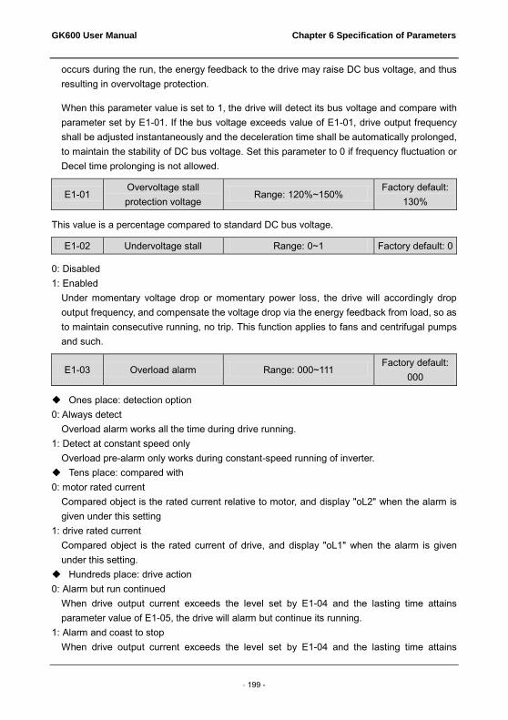
GK600 User Manual Chapter 6 Specification of Parameters
- 199 -
occurs during the run, the energy feedback to the drive may raise DC bus voltage, and thus resulting in overvoltage protection.
When this parameter value is set to 1, the drive will detect its bus voltage and compare with parameter set by E1-01. If the bus voltage exceeds value of E1-01, drive output frequency shall be adjusted instantaneously and the deceleration time shall be automatically prolonged, to maintain the stability of DC bus voltage. Set this parameter to 0 if frequency fluctuation or Decel time prolonging is not allowed.
E1-01 Overvoltage stall protection voltage
Range: 120%~150% Factory default:
130%
This value is a percentage compared to standard DC bus voltage.
E1-02 Undervoltage stall Range: 0~1 Factory default: 0
0: Disabled 1: Enabled
Under momentary voltage drop or momentary power loss, the drive will accordingly drop output frequency, and compensate the voltage drop via the energy feedback from load, so as to maintain consecutive running, no trip. This function applies to fans and centrifugal pumps and such.
E1-03 Overload alarm Range: 000~111 Factory default:
000
Ones place: detection option 0: Always detect
Overload alarm works all the time during drive running. 1: Detect at constant speed only
Overload pre-alarm only works during constant-speed running of inverter. Tens place: compared with 0: motor rated current
Compared object is the rated current relative to motor, and display "oL2" when the alarm is given under this setting
1: drive rated current Compared object is the rated current of drive, and display "oL1" when the alarm is given under this setting.
Hundreds place: drive action 0: Alarm but run continued
When drive output current exceeds the level set by E1-04 and the lasting time attains parameter value of E1-05, the drive will alarm but continue its running.
1: Alarm and coast to stop When drive output current exceeds the level set by E1-04 and the lasting time attains

Chapter 6 Specification of Parameters GK600 User Manual
- 200 -
parameter value of E1-05, the drive will display overload fault and coast to stop.
E1-04 Overload alarm threshold Range: 20.0%~200.0% Factory default:
130.0%
When tens place of E1-03 is set to 0, this parameter value is a percentage compared to rated current of motor. When tens place of E1-03 is set to 1, this parameter value is a percentage compared to rated current of drive.
E1-05 Overload alarm activation
time Range: 0.1s~60.0s
Factory default: 5.0s
Sets the lasting time that overload alarm is activated when output current of drive is bigger than the threshold set by E1-04.
E1-06 Protection action 1 Range: 0000~1111 Factory default:
0000
E1-07 Protection action 2 Range: 0000~3111 Factory default:
3001
These two parameters set the protection action of the drive in the following abnormal status.
Specification of E1-06: Ones place: reserved Tens place: temperature measurement circuit fault (OH3) 0: Coast to stop 1: Alarm but run continued Hundreds place: abnormal EEPROM (EPr) 0: Coast to stop 1: Alarm but run continued Thousands place: abnormal terminal communication (TrC) 0: Coast to stop 1: Alarm but run continued
Specification of E1- 07: Ones place: abnormal power supply when running (SUE) 0: Coast to stop 1: Alarm but run continued Tens place: current detection circuit failed (CtC) 0: Coast to stop 1: Alarm but run continued Hundreds place: abnormal contactor (CCL) 0: Coast to stop 1: Alarm but run continued
GK600 User Manual Chapter 6 Specification of Parameters
- 201 -
Thousands place: input supply fault /output phase loss (ISF, oPL) 0: Protection for neither input supply fault nor output phase loss 1: No protection for input supply fault, protection enabled for output phase loss 2: Protection enabled for input supply fault, no protection for output phase loss 3: Protection enabled both for input supply fault and output phase loss
ATTENTION: Please set "protection action" with caution since inappropriate setting may extend the fault.
E1-08 Fault memory after power
loss Range: 0~1 Factory default: 0
Determine whether or not the previous fault code is to be memorized and displayed upon the power up of the drive after power loss. 0: Not memorized after power loss 1: Memorized after power loss
ATTENTION: Undervoltage fault "LoU" is not memorized after power loss.
E1-09 Fault auto-reset times Range: 0~20 Factory default: 0
E1-10 Auto-reset interval Range: 2.0s~20.0s Factory default:
2.0s
When a fault occurs during the running, the drive will run at 0Hz with the time set by E1-10, and then the fault will be reset and the drive continues to run. Times of automatic reset is set by E1-09. Automatic reset is prohibited and fault protection shall be executed immediately when E1-09 is set to 0.
ATTENTION: 1) Automatic fault reset is not performed at the following types of faults: Module protection "FAL" Parameter identification failed "tUN" Current detection abnormal "CtC" Ground short circuit protection at output side "GdP" Option board 1 connection abnormal "EC1" Converter module overload protection "oL3" Drive line connection abnormal "dLC" Analog terminal functional mutex (TEr) External equipment error "PEr" Consecutive run time attained "to2" Accumulative run time attained fault "to3" Power supply abnormal during running "SUE"

Chapter 6 Specification of Parameters GK600 User Manual
- 202 -
Parameter copy fault "CPy" Software version compatibility failure "SFt" CPU interference fault "CPU" Reference protection "oCr" 5V power supply out-of-limit "SP1" Undervoltage protection "LoU" PID feedback loss ”Plo”
2) Please use automatic fault reset function with caution, or fault will be extended.
E1-11 Relay action on drive fault Range: 000~111 Factory default:
010
Ones place: when undervoltage fault occurs 0: No action 1: Action enabled Set whether or not fault relay acts when undervoltage occurs. Tens place: when fault locked 0: No action 1: Action enabled
Set whether or not the relay acts when the fault locked at latest power loss after power up. Hundred's place: at interval of auto- reset 0: No action 1: Action enabled
Set whether or not the relay acts when fault occurs in automatic reset status.
E1-12 Cooling fan control Range: 0~1 Factory default: 0
0: Auto run The fans run all the time during the running. Determine if the fans continue to run or stop according to module temperature after stop.
1: Always run after power up The fans run all the time after applying power to the drive.
E1-13 Drive overheat alarm
threshold Range: 0.0℃~100.0℃
Factory default: 80.0℃
This parameter sets the threshold of drive overheat alarm.
Group F Application
Group F0 Process PID
The purpose of process PID control is to make feedback value consistent with the set value. PID control diagram is shown as Fig. 6-48.
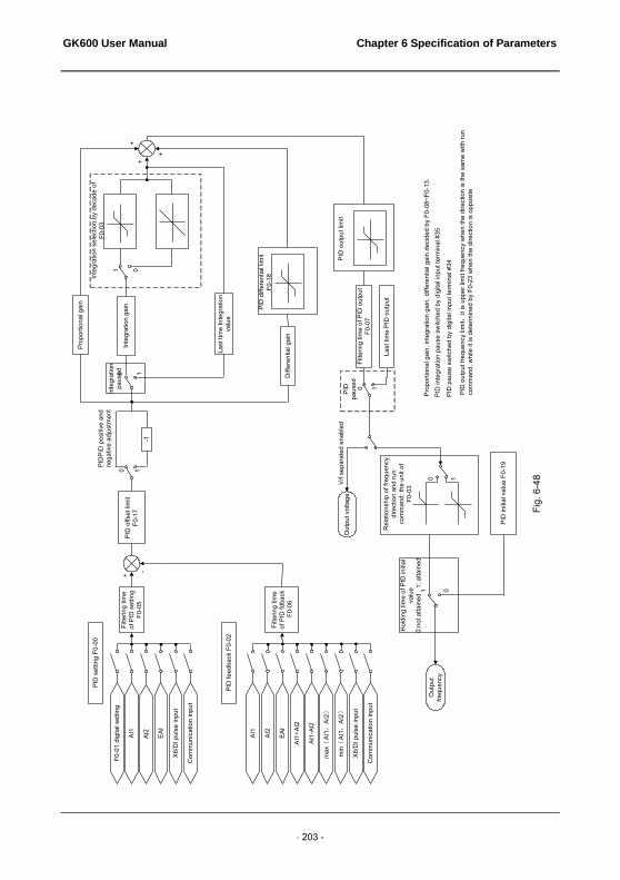
GK600 User Manual Chapter 6 Specification of Parameters
- 203 -
EAI
AI2
AI1
AI1
min{
AI1,
AI2}
max
{AI
1,AI
2}
AI1-
AI2
AI1+
AI2
EAI
AI2
X6/D
I pul
se in
put
Com
mun
icat
ion
inpu
t
PID
feed
back
F0-
02
+
--1
0 1
Prop
ortio
nal g
ain
Inte
grat
ion
gain
01
Inte
grat
ion
sele
ctio
n by
dec
ade
of
F0-0
3
Diff
eren
tial g
ain
PID
diff
eren
tial l
imit
F0-1
8
Last
tim
e In
tegr
atio
n va
lue
0 1
PID
out
put l
imit
Filte
ring
time
of P
ID o
utpu
t F0
-07
Last
tim
e PI
D o
utpu
t
0 1PID
pa
used
Out
put v
olta
ge
0 1
Rel
atio
nshi
p of
freq
uenc
y di
rect
ion
and
run
com
man
d: th
e un
it of
F0
-03
PID
initi
al v
alue
F0-
19
01
Hol
ding
tim
e of
PID
initi
al
valu
e 0:
not a
ttain
ed
1: a
ttain
ed
Out
put
frequ
ency
+
++
Filte
ring
time
of P
ID fd
back
F0-
06
Prop
ortio
nal g
ain,
inte
grat
ion
gain
, diff
eren
tial g
ain
deci
ded
by F
0-08
~F0-
13.
PID
inte
grat
ion
paus
e sw
itche
d by
dig
ital i
nput
term
inal
#35
PID
pau
se s
witc
hed
by d
igita
l inp
ut te
rmin
al #
34
PID
out
put f
requ
ency
lim
it:it
is u
pper
lim
it fre
quen
cy w
hen
the
dire
ctio
n is
the
sam
e w
ith ru
n co
mm
and,
whi
le it
is d
eter
min
ed b
y F0
-23
whe
n th
e di
rect
ion
is o
ppos
ite
F0-0
1 di
gita
l set
ting
X6/D
I pul
se in
put
Com
mun
icat
ion
inpu
t
PID
set
ting
F0-0
0
Filte
ring
time
of P
ID s
ettin
g F0
-05
PID
offs
et li
mit
F0
-17
PID
PID
pos
itive
and
ne
gativ
e ad
just
men
t In
tegr
atio
n pa
used
Fig.
6-4
8
V/f s
epar
ated
ena
bled

Chapter 6 Specification of Parameters GK600 User Manual
- 204 -
F0-00 PID setting Range: 0~5 Factory default: 0
Select the setting source of PID control. 0: F0-01 digital setting 1:AI1 2:AI2 3: EAI (on IO option board) 4: X6/DI pulse input 5: Communication
F0-01 PID digital setting Range: 0.0%~100.0% Factory default:
50.0%
When F0-00 is set to 0, this parameter value is taken as the set value of PID.
F0-02 PID feedback Range: 0~8 Factory default: 0
Select the feedback source of PID control. 0:AI1 1:AI2 2: EAI (on IO option board) 3:AI1+AI2 4:AI1-AI2 5:max{AI1,AI2} 6:min{AI1,AI2} 7: X6/DI pulse input 8: Communication
F0-03 PID adjustment Range: 00~11 Factory default: 11
Ones place: output frequency 0: Must be the same direction as the set run direction
When PID frequency output direction is opposite to the rotary set direction, PID output is 0. 1: Opposite direction allowed
PID frequency output direction can be opposite to the rotary set direction, and PID output performs normally.
Tens place: integration selection 0: Integral continued when frequency attains upper/lower frequency
Under PID control, when output frequency attains upper/lower limit of frequency or parameter value of F0-23 (maximum frequency if it is opposite to the rotary set direction), PID integral continues. This mode requires longer time of quitting saturation.
1: Integral stopped when frequency attains upper/lower limit Under PID control, when output frequency attains upper/lower limit of frequency or parameter value of F0-23 (maximum frequency if it is opposite to the rotary set direction), PID

GK600 User Manual Chapter 6 Specification of Parameters
- 205 -
integral will cease. This mode can quit integral saturation status rapidly.
F0-04 PID positive and negative adjustment Range: 0~1 Factory default: 0
0: Positive adjustment 1: Negative adjustment This parameter can be used with digital input terminal "PID adjustment direction" to select positive or negative adjustment of PID.
Table 6-17
F0-04 PID adjustment direction terminal
Adjustment
0 OFF Positive 0 ON Negative 1 OFF Negative 1 ON Positive
Positive adjustment: when feedback signal is smaller than PID setting, output frequency of the
drive will rise to reach PID balance. when feedback signal is bigger than PID setting, output frequency of the drive will drop to reach PID balance.
Negative adjustment: when feedback signal is smaller than PID setting, output frequency of the drive will drop to reach PID balance. when feedback signal is bigger than PID setting, output frequency of the drive will rise to reach PID balance.
F0-05 Filtering time of PID setting Range: 0.00s~60.00s Factory default:
0.00s
F0-06 Filtering time of PID feedback
Range: 0.00s~60.00s Factory default:
0.00s
F0-07 Filtering time of PID output Range: 0.00s~60.00s Factory default:
0.00s
Set the filtering time of PID setting, feedback and output.
F0-08 Proportional gain Kp1 Range: 0.0~100.0 Factory default:
50.0
F0-09 Integration time Ti1 Range: 0.000s~50.000s Factory default:
0.500s
F0-10 Derivative time Td1 Range: 0.000s~50.000s Factory default:
0.0s

Chapter 6 Specification of Parameters GK600 User Manual
- 206 -
Process PID is provided with two groups of proportion, integral and differential parameters set by F0-14. F0-08~F0-10 are the first group of parameters.
Proportional gain Kp: dynamic response of the system can be quickened by increasing proportional gain Kp. However, excessive Kp value would bring about system oscillation. Only proportional gain control cannot eliminate steady state error.
Integration time: dynamic response of the system can be quickened by reducing integration time Ti. However, excessively small Ti value would result in serious system overshooting and may easily bring about oscillation. Integral control can be used to eliminate steady state error but is unable to control sharp changes.
Differential time Td: it can predict the change trend of offset and thus can rapidly respond to the change, improving dynamic performance. However, this is vulnerable to interference. Please use differential control with caution.
F0-11 Proportional gain Kp2 Range: 0.0~100.0 Factory default:
50.0
F0-12 Integration time Ti2 Range: 0.0s~100.0s Factory default:
0.5s
F0-13 Derivative time Td2 Range: 0.000s~50.000s Factory default:
0.000s
Process PID is provided with two groups of proportion, integral and differential parameters set by F0-14. F0-11~ F0-13 are the second group of parameters.
F0-14 PID parameter switchover Range: 0~2 Factory default: 0
Process PID is provided with two groups of proportional, integral and differential parameters, which is set by this parameter. 0: No switch, determined by parameters Kp1, Ti1 and Td1
Always determined by Kp1, Ti1 and Td1 set at F0-08~F0-10. 1: Auto switched on the basis of input offset
When the offset between setting and feedback is less than the set value of F0-15, PID adjustment is determined by Kp1, Ti1 and Td1. When the offset between setting and feedback is bigger than the set value of F0-15, PID adjustment is determined by Kp2, Ti2 and Td2 set at F0-11~F0-13.
2: Switched by terminal When digital input terminal "PID parameters switch" is OFF, it is determined by Kp1, Ti1 and Td1. When "PID parameters switch" is ON, it is determined by Kp2, Ti2 and Td2
F0-15 Input offset under
PID auto switch Range: 0.0%~100.0% Factory default:
20.0%

GK600 User Manual Chapter 6 Specification of Parameters
- 207 -
When F0-14 is set to 1, this parameter sets the switching point of the two groups of PID parameters. When the offset between setting and feedback is less than this set value, it is determined by Kp1, Ti1 and Td1. When the offset between setting and feedback is bigger than this set value, it is determined by Kp2, Ti2 and Td2.
F0-16 Sampling period T Range: 0.001s~50.000s Factory default:
0.002s
Sampling period aims at feedback. PID controller performs the sampling and compute once in each sampling period. The longer the sampling period T is, the slower the response time will be.
F0-17 PID offset limit Range: 0.0%~100.0% Factory default:
0.0%
If the offset between PID feedback and setting is more than this set value, PID regulator will implement regulation. If the offset between PID feedback and setting is less than this set value, PID will stop the regulation and the PID controller output will be kept unchanged. This function can improve the stability of PID performance.
F0-18 PID derivative limit Range: 0.0%~100.0% Factory default:
0.5%
Sets differential output limit of PID control.
F0-19 PID initial value Range: 0.0%~100.0% Factory default:
0.0%
F0-20 PID initial value holding
time Range: 0.0s~3600.0s
Factory default: 0.0s
PID does not make adjustment when the drive starts its running, but outputs the value set by F0-19 and maintains the holding time set by F0-20, then starts PID adjustment. When F0-20 is set to 0, PID initial value is disabled. This function makes PID adjustment get into stable status fast.
F0-21 PID feedback loss
detection value Range: 0.0%~100.0%
Factory default: 0.0%
F0-22 PID feedback loss
detection time Range: 0.0s~30.0s
Factory default: 1.0s
When offset between feedback and setting of PID is bigger than set value of F0-21 and the lasting time attains the set time of F0-22, the drive reports fault "Plo". If F0-22 is set to 0, feedback loss detection is disabled.

Chapter 6 Specification of Parameters GK600 User Manual
- 208 -
F0-23 Cutoff FREQ when opposite to rotary set direction
Range: 0.00Hz~maximum frequency
Factory default: 50.00Hz
When rotary set direction is forward, while PID output is reverse, the maximum reverse frequency will be determined by F0-23. When rotary set direction is reverse, while PID output is forward, the maximum forward frequency will be determined by F0-23.
F0-24 PID computation option Range: 0~1 Factory default: 0
0: No computation in stop status 1: Computation continued in stop status
Group F1 Multi-step Frequency
F1-00 FREQ set source of multi-step 0
Range: 0~8 Factory default: 0
0: Digital setting F1-02 1: Digital setting b0-02 + control panel ∧/∨ adjustment 2: Digital setting b0-02 + terminal UP/DOWN adjustment 3:AI1 4:AI2 5: EAI (on IO option board) 6: X6/DI pulse input 7: Process PID output 8: Communication At most 16-step of frequency can be set through the combination of "multi-step frequency terminals 1~4" of digital input. Multi-step frequency 2~15 are only digital setting while a number of setting sources can be selected for multi-step frequency 0~1. Parameter value of F1-00 determines command source of step 0.
F1-01 FREQ set source of multi-step 1 Range: 0~8 Factory default: 0
0: Digital setting F1-03 1: Digital setting b0-04 + control panel ∧/∨ adjustment 2: Digital setting b0-04 + terminal UP/DOWN adjustment 3:AI1 4:AI2 5: EAI (on IO option) 6: X6/DI pulse input 7: Process PID output 8: Communication

GK600 User Manual Chapter 6 Specification of Parameters
- 209 -
At most 16-step of frequency can be set through the combination of "multi-step frequency terminals 1~4" of digital input. Multi-step frequency 2~15 are only digital setting while a number of setting sources can be selected for multi-step frequency 0~1. Parameter value of F1-01 determines command source of step 1.
F1-02 Multi-step frequency 0 Lower limit frequency ~ upper
limit frequency Factory default:
0.00Hz
F1-03 Multi-step frequency 1 Lower limit frequency ~ upper
limit frequency Factory default:
0.00 Hz
F1-04 Multi-step frequency 2 Lower limit frequency ~ upper
limit frequency Factory default:
0.00 Hz
F1-05 Multi-step frequency 3 Lower limit frequency ~ upper limit frequency
Factory default: 0.00 Hz
F1-06 Multi-step frequency 4 Lower limit frequency ~ upper limit frequency
Factory default: 0.00 Hz
F1-07 Multi-step frequency 5 Lower limit frequency ~ upper limit frequency
Factory default: 0.00 Hz
F1-08 Multi-step frequency 6 Lower limit frequency ~ upper limit frequency
Factory default: 0.00 Hz
F1-09 Multi-step frequency 7 Lower limit frequency ~ upper limit frequency
Factory default: 0.00 Hz
F1-10 Multi-step frequency 8 Lower limit frequency ~ upper limit frequency
Factory default: 0.00 Hz
F1-11 Multi-step frequency 9 Lower limit frequency ~ upper limit frequency
Factory default: 0.00 Hz
F1-12 Multi-step frequency 10 Lower limit frequency ~ upper limit frequency
Factory default: 0.00 Hz
F1-13 Multi-step frequency 11 Lower limit frequency ~ upper limit frequency
Factory default: 0.00 Hz
F1-14 Multi-step frequency 12 Lower limit frequency ~ upper limit frequency
Factory default: 0.00 Hz
F1-15 Multi-step frequency 13 Lower limit frequency ~ upper limit frequency
Factory default: 0.00 Hz
F1-16 Multi-step frequency 14 Lower limit frequency ~ upper limit frequency
Factory default: 0.00 Hz
F1-17 Multi-step frequency 15 Lower limit frequency ~ upper limit frequency
Factory default: 0.00 Hz
At most 16 steps of multi-step frequency can be set by different status combinations of "multi-step frequency terminals 1~4" of digital input, as shown in Table 6-18.

Chapter 6 Specification of Parameters GK600 User Manual
- 210 -
Table 6-18
Multi-step terminal 4
Multi-step terminal 3
Multi-step terminal 2
Multi-step terminal 1
Command frequency
OFF OFF OFF OFF Multi-step frequency
0(F1-00)
OFF OFF OFF ON Multi-step frequency
1(F1-01)
OFF OFF ON OFF Multi-step frequency
2(F1-04)
OFF OFF ON ON Multi-step frequency
3(F1-05)
OFF ON OFF OFF Multi-step frequency
4(F1-06)
OFF ON OFF ON Multi-step frequency
5(F1-07)
OFF ON ON OFF Multi-step frequency
6(F1-08)
OFF ON ON ON Multi-step frequency
7(F1-09)
ON OFF OFF OFF Multi-step frequency
8(F1-10)
ON OFF OFF ON Multi-step frequency
9(F1-11)
ON OFF ON OFF Multi-step frequency
10(F1-12)
ON OFF ON ON Multi-step frequency
11(F1-13)
ON ON OFF OFF Multi-step frequency
12(F1-14)
ON ON OFF ON Multi-step frequency
13(F1-15)
ON ON ON OFF Multi-step frequency
14(F1-16)
ON ON ON ON Multi-step frequency
15(F1-17)

GK600 User Manual Chapter 6 Specification of Parameters
- 211 -
Group F2 Simple PLC
Simple PLC is a multi-step frequency generator. The drive can automatically change run frequency and direction based on the run time so as to meet on-site technological requirements. Flow chart is shown as Fig. 6-49.
Fig. 6-49
a0~a15 are the Accel times of steps, while d0~d15 are the Decel times. f0~f15 are the set frequencies of steps while T0~T15 are the run times.
Upon the completion of current step of simple PLC, digital output terminal "PLC step completed" outputs ON signal, 500ms. When simple PLC finishes a run cycle, digital output terminal "PLC cycle completed" outputs ON signal, 500ms.
F2-00 Simple PLC run mode Range: 0000~1212 Factory default:
0000
Ones place: PLC run mode 0: Stop after a single cycle
PLC stops upon the completion of one cycle and it won’t be started unless another run command is given, shown as Fig. 6-50.
a0a1
a2a3
a4a5
a6a7
a8
a9
a10
a11
d13
a14
a15 d15
d12
d8
f7
f0f1
f2f3
f4f5
f8
f9
f10
f11
f12
f13
f14
f15f6
a13
T0 T1 T2 T3 T4 T5 T6 T7 T8 T9 T10 T11 T12 T13 T14 T15
PLC阶段完成
PLC循环完成
500ms宽度的脉冲PLC step completed
PLC cycle completed
Pulse length: 500ms

Chapter 6 Specification of Parameters GK600 User Manual
- 212 -
Fig. 6-50
1: Continue to run in the last FREQ after a single cycle After the completion of one cycle, PLC maintains the run frequency and direction of the last step. See the figure below:
Fig. 6-51
a0a1
a2a3
a4a5
a6a7
a8
a9
a10
a11
d13
a14
a15 d15
d12
d8
f7
f0f1
f2f3
f4f5
f8
f9
f10
f11
f12
f13
f14
f15f6
a13
T0 T1 T2 T3 T4 T5 T6 T7 T8 T9 T10 T11 T12 T13 T14 T15
PLC阶段完成
PLC循环完成
500ms宽度的脉冲
运行命令
a0a1
a2a3
a4a5
a6a7
a8
a9
a10
a11
d13
a14
a15
d12
d8
f7
f0f1
f2f3
f4f5
f8
f9
f10
f11
f12
f13
f14
f15f6
a13
T0 T1 T2 T3 T4 T5 T6 T7 T8 T9 T10 T11 T12 T13 T14 T15
PLC阶段完成
PLC循环完成
500ms宽度的脉冲
运行命令
PLC step completed
PLC cycle completed
Pulse length: 500ms
Run command
PLC step completed
PLC cycle completed
Pulse length: 500ms
Run command

GK600 User Manual Chapter 6 Specification of Parameters
- 213 -
2: Cycle repeated PLC automatically starts another cycle after finishing one cycle until there is a stop command, shown as Fig. 6-52.
Fig. 6-52
Tens place: power loss memory 0: No memory on power loss
The drive does not memorize PLC run status on power loss and starts the run from step 0 after power up again.
1: Memorized on power loss The drive saves PLC run status on power loss, including the run step, run frequency and finished run time at the moment of power loss. After the next power up, the run will be continued in accordance with the memorized status.
Hundreds place: starting mode 0: Run from the first step “multi-step frequency 0”
When restarted after stop, the drive will start to run from “step 0”. 1: Continue to run from the step of stop (or fault)
At the moment drive stop, the drive automatically records the run time of current step. When restarted, the drive will gets into this step, continue to run the remanent time with the frequency of this step, shown as Fig. 6-53.
a0a1
a2a3
a4a5
a6a7
a8
a9
a10
a11
d13
a14
a15
d12
d8
f7
f0f1
f2f3
f4f5
f8
f9
f10
f11
f12
f13
f14
f15f6
a13
T0 T1 T2 T3 T4 T5 T6 T7 T8 T9 T10 T11 T12 T13 T14 T15
PLC阶段完成
PLC循环完成
500ms宽度的脉冲
运行命令
d0
f0
PLC step completed
PLC cycle completed
Pulse length: 500ms
Run command

Chapter 6 Specification of Parameters GK600 User Manual
- 214 -
Fig. 6-53
2: Continue to run from the step and frequency at which the run stopped (or fault occurred) At the moment of stop, the drive not only records the run time of current step, but also records the run frequency at the moment of stop. When restarted, it will restore the run frequency that was recorded at the moment of stop, and then continue to run the remanent step, as shown in Fig. 6-54:
Fig. 6-54
Thousands place: unit of simple PLC run time 0: Second 1: Minute Sets the unit of running time and Accel/Decel time of simple PLC.
输出频率
时间
阶段0运行时间
阶段1运行时间
阶段2已运行时间
阶段2剩余
运行时间
阶段3运行时间
运行命令
故障,自由停车
a0f0
a1
f1d2
a2f2
a3
f3
输出频率
时间
阶段0运行时间
阶段1运行时间
阶段2已运行时间
阶段2剩余
运行时间
阶段3运行时间
运行命令
故障,自由停车
a0f0
a1
f1d2
a2 f2
a3
f3
d2
Output frequency
Coast to stop at fault
Run time of step 0
Run time of step 1
Run time of step 2
Remanent time of step 2
Run time of step 3
Time
Run command
Output frequency
Coast to stop at fault
Run time of step 0
Run time of step 1
Run time of step 2
Remanent time of step 2
Run time of step 3
Time
Run command

GK600 User Manual Chapter 6 Specification of Parameters
- 215 -
F2-01 Setting of multi-step 0 Range: 000~327 Factory default:
000
Ones place: frequency setting Sets the frequency of step 0 of simple PLC. 0: Multi-step frequency 0 (F1-02) 1:AI1 2:AI2 3: EAI (on IO option board) 4: X6/DI pulse input 5: Process PID output 6: Multi-step frequency 7: Communication Tens place: run direction Sets the run direction for step 0 of simple PLC. 0: Forward 1: Reverse 2: Determined by run command Hundreds place: Accel/Decel time option Sets the Accel/Decel time step 0. 0: Accel/Decel time 1 1: Accel/Decel time 2 2: Accel/Decel time 3 3: Accel/Decel time 4 The Accel/Decel time of simple PLC running is set here, not determined by digital input terminal "Accel/Decel time determinant 1~2". In addition, Accel/Decel time unit is set through thousands place of F2-00 and is independent of the setting of b2-00.
F2-02 Run time of step 0 Range: 0.0~6000.0s(min) Factory default:
0.0s
Sets the run time for step 0 of simple PLC and the time unit is set by thousands place of F2-00.
F2-03 Setting of step 1 Range: 000~327 Factory default:
000
Ones place: frequency setting 0: Multi-step frequency 1 (F1-03) 1~7: same as F2-01 Tens place: run direction (same as F2-01) Hundreds place: Accel/Decel time option (same as F2-01)

Chapter 6 Specification of Parameters GK600 User Manual
- 216 -
F2-04 Run time of step 1 Range: 0.0~6000.0s(min) Factory default:
0.0s
Sets the run time for step 1 of simple PLC and the time unit is set by thousands place of F2-00.
F2-05 Setting of step 2 Range: 000~327 Factory default:
000
Ones place: frequency setting 0: Multi-step frequency 2 (F1-04) 1~7: same as F2-01 Tens place: run direction (same as F2-01) Hundreds place: Accel/Decel time option (same as F2-01)
F2-06 Run time of step 2 Range: 0.0~6000.0s(min) Factory default:
0.0s
Sets the run time of step 2. The time unit is set by thousands place of F2-00.
F2-07 Setting of step 3 Range: 000~327 Factory default:
000
Ones place: frequency setting 0: Multi-step frequency 3 (F1-05)
1~7: same as F2-01 Tens place: run direction (same as F2-01) Hundreds place: Accel/Decel time option (same as F2-01)
F2-08 Run time of step 3 Range: 0.0~6000.0s(min) Factory default:
0.0s
Sets the run time of step 3 of simple PLC. The time unit is set by thousands place of F2-00.
F2-09 Setting of step 4 Range: 000~327 Factory default:
000
Ones place: frequency setting 0: Multi-step frequency 4 (F1-06) 1~7: same as F2-01 Tens place: run direction (same as F2-01) Hundreds place: Accel/Decel time option (same as F2-01)
F2-10 Run time of step 4 Range: 0.0~6000.0s(min) Factory default:
0.0s
Sets the run time of step 4 of simple PLC. The time unit is set by thousands place of F2-00.

GK600 User Manual Chapter 6 Specification of Parameters
- 217 -
F2-11 Setting of step 5 Range: 000~327 Factory default:
000
Ones place: frequency setting 0: Multi-step frequency 5 (F1-07) 1~7: same as F2-01 Tens place: run direction (same as F2-01) Hundreds place: Accel/Decel time option (same as F2-01)
F2-12 Run time of step 5 Range: 0.0~6000.0s(min) Factory default:
0.0s
Sets the run time of step 5 of simple PLC. The time unit is set by thousands place of F2-00.
F2-13 Setting of step 6 Range: 000~327 Factory default:
000
Ones place: frequency setting 0: Multi-step frequency 6 (F1-08) 1~7: same as F2-01 Tens place: run direction (same as F2-01) Hundreds place: Accel/Decel time option (same as F2-01)
F2-14 Run time of step 6 Range: 0.0~6000.0s(min) Factory default:
0.0s
Sets the run time of step 6 of simple PLC. The time unit is set by thousands place of F2-00.
F2-15 Setting of step 7 Range: 000~327 Factory default:
000
Ones place: frequency setting 0: Multi-step frequency 7 (F1-09) 1~7: same as F2-01 Tens place: run direction (same as F2-01) Hundreds place: Accel/Decel time option (same as F2-01)
F2-16 Run time of step 7 Range: 0.0~6000.0s(min) Factory default:
0.0s
Sets the run time of step 7 of simple PLC. The time unit is set by thousands place of F2-00.
F2-17 Setting of step 8 Range: 000~327 Factory default:
000
Chapter 6 Specification of Parameters GK600 User Manual
- 218 -
Ones place: frequency setting 0: Multi-step frequency 8 (F1-10) 1~7: same as F2-01 Tens place: run direction (same as F2-01) Hundreds place: Accel/Decel time option (same as F2-01)
F2-18 Run time of step 8 Range: 0.0~6000.0s(min) Factory default:
0.0s
Sets the run time of step 8 of simple PLC. The time unit is set by thousands place of F2-00.
F2-19 Setting of step 9 Range: 000~327 Factory default:
000
Ones place: frequency setting 0: Multi-step frequency 9 (F1-11) 1~7: same as F2-01 Tens place: run direction (same as F2-01) Hundred's place: Accel/Decel time option (same as F2-01)
F2-20 Run time of step 9 Range: 0.0~6000.0s(min) Factory default:
0.0s
Sets the run time for step 9 of simple PLC. The time unit is set by thousands place of F2-00.
F2-21 Setting of step 10 Range: 000~327 Factory default:
000
Ones place: frequency setting 0: Multi-step frequency 10 (F1-12) 1~7: same as F2-01 Tens place: run direction (same as F2-01) Hundreds place: Accel/Decel time option (same as F2-01)
F2-22 Run time of step 10 Range: 0.0~6000.0s(min) Factory default:
0.0s
Sets the run time of step 10 of simple PLC. The time unit is set by thousands place of F2-00.
F2-23 Setting of step 11 Range: 000~327 Factory default:
000
Ones place: frequency setting 0: Multi-step frequency 11 (F1-13) 1~7: same as F2-01

GK600 User Manual Chapter 6 Specification of Parameters
- 219 -
Tens place: run direction (same as F2-01) Hundreds place: Accel/Decel time option (same as F2-01)
F2-24 Run time of step 11 Range: 0.0~6000.0s(min) Factory default:
0.0s
Sets the run time of step 11 of simple PLC. The time unit is set by thousands place of F2-00.
F2-25 Setting of step 12 Range: 000~327 Factory default:
000
Ones place: frequency setting 0: Multi-step frequency 12 (F1-14) 1~7: same as F2-01 Tens place: run direction (same as F2-01) Hundreds place: Accel/Decel time option (same as F2-01)
F2-26 Running time of step 12 Range: 0.0~6000.0s(min) Factory default:
0.0s
Sets the run time of step 12 of simple PLC. The time unit is set by thousands place of F2-00.
F2-27 Setting of step 13 Range: 000~327 Factory default:
000
Ones place: frequency setting 0: The time unit is set by thousands place of F2-00. 1~7: same as F2-01 Tens place: run direction (same as F2-01) Hundreds place: Accel/Decel time option (same as F2-01)
F2-28 Run time of step 13 Range: 0.0~6000.0s(min) Factory default:
0.0s
Sets the run time of step 13 of simple PLC. The time unit is set by thousands place of F2-00.
F2-29 Setting of step 14 Range: 000~327 Factory default:
000
Ones place: frequency setting 0: Multi-step frequency 14 (F1-16) 1~7: same as F2-01 Tens place: run direction (same as F2-01) Hundreds place: Accel/Decel time option (same as F2-01)

Chapter 6 Specification of Parameters GK600 User Manual
- 220 -
F2-30 Run time of step 14 Range: 0.0~6000.0s(min) Factory default:
0.0s
Sets the run time of step 14 of simple PLC. The time unit is set by thousands place of F2-00.
F2-31 Setting of step 15 Range: 000~327 Factory default:
000
Ones place: frequency setting 0: Multi-step frequency 15 (F1-17) 1~7: same as F2-01 Tens place: run direction (same as F2-01) Hundreds place: Accel/Decel time option (same as F2-01)
F2-32 Run time of step 15 Range: 0.0~6000.0s(min) Factory default:
0.0s
Sets the run time for step 15 of simple PLC. The time unit is set by thousand's place of F2-00.
ATTENTION: Digital input terminals "simple PLC paused", "simple PLC disabled" and "simple PLC stop memory clear" can be used during the running of simple PLC. See specification of digital input of Group C0 for details.
Group F3 Wobble Frequency and Fixed Length Count
Wobble frequency function is usually used in textile and chemical fiber industries where traverse motion is required. Wobble frequency control process is as follows: accelerate to the pre-frequency of wobble frequency function according to the current Accel time. Maintain this frequency for a period of time and run to center frequency of wobble frequency according to the current Accel/Decel time (i.e. the set frequency set by parameter group b0). Then run in a cyclic manner according to wobble frequency amplitude, hopping frequency, wobble frequency cycle time, and frequency ramp up time. When a stop command is given, the drive will ramp down to stop according to the set Decel time.

GK600 User Manual Chapter 6 Specification of Parameters
- 221 -
Fig. 6-55
a is the set Accel time (ramp up time), and d is the set Decel time (ramp down time).
F3-00 Wobble frequency function setting Range: 0~1 Factory default: 0
0: Wobble frequency function disabled 1: Wobble frequency function enabled
F3-01 Wobble frequency run setting Range: 0000~1111 Factory default:
0000
Ones place: started method 0: Automatically
Run at pre-frequency of wobble frequency set by F3-02, maintain Pre-frequency holding time
set by F3-03, and then automatically get into wobble frequency run.
1: Started by terminal Digital input terminal "start wobble frequency" controls the run of wobble frequency. When
terminal inputs ON, the drive gets into wobble frequency run. When terminal inputs OFF, the
drive exits wobble frequency and runs at pre-frequency of wobble frequency. Under this
mode, Pre-frequency holding time is enabled.
Tens place: amplitude control 0: Relative to center frequency
Amplitude = F3-04 x current frequency setting. 1: Relative to maximum frequency
输出频率
时间
ad
a
摆频预置频率保持
时间 摆频周期(F3-06)
三角波
上升时间
突跳频率
摆频频率上限
摆频频率下限
摆频中心频率
摆频预置频率
摆频正幅度
摆频负幅度
运行命令 停机命令
Output frequency Wobble frequency positive amplitude
Wobble frequency negative amplitude
Hop frequency
Upper limit of wobble frequency
Center frequency
Lower limit of wobble frequency Pre-wobble frequency
Pre- wobble frequency
holding time
Triangular wave rise time
Wobble frequency
cycle (F3-06)
Time
Run command Stop command

Chapter 6 Specification of Parameters GK600 User Manual
- 222 -
Amplitude = F3-04 x maximum frequency b0-08. Hundreds place: wobble frequency memorized when stop 0: Memory enabled
The drive memorizes the current wobble frequency state when stop. When restarted, drive continues to run the wobble frequency with the memorized state at latest stop. Pre-frequency of wobble frequency F3-02 is enabled at restart.
1: Memory disabled
When the drive is started, it restarts wobble frequency running. Run at pre-frequency of wobble frequency F3-02, maintain this frequency for pre-frequency holding time F3-03, and then automatically gets into wobble frequency control.
Thousands place: wobble frequency memorized on power loss 0: Memory enabled
Automatically save the wobble frequency state on power loss. This function takes effect only under wobble frequency running.
1: Memory disabled Drive clears wobble frequency status on power loss.
F3-02 Pre-wobble frequency Range: 0.00Hz~600.00Hz Factory default:
0.00Hz
F3-03 Pre-wobble frequency
holding time Range: 0.0s~3600.0s
Factory default: 0.0s
During the run of wobble frequency, F3-02 is the run frequency before the drive begins to run at wobble frequency, while F3-03 is the holding time of pre-wobble frequency. When F3-03 is set to 0, pre-frequency is disabled.
F3-04 Wobble frequency
amplitude Range: 0.0%~50.0%
Factory default: 0.0%
The percentage is relative to center frequency or maximum frequency and determined by the tens place of F3-01. Center frequency is the frequency setting determined by parameters of Group b0.
Run frequency of wobble frequency is not only subject to this amplitude, but is also restricted by upper limit and lower limit of frequency.
F3-05 Hop frequency Range: 0.0%~50.0% Factory default:
0.0%
Hop frequency = F3-05 × amplitude.

GK600 User Manual Chapter 6 Specification of Parameters
- 223 -
F3-06 Cycle of wobble frequency Range: 0.1s~999.9s Factory default:
0.0s
The time of the completion of a complete process of wobble frequency
F3-07 Triangular wave ramp-up time Range: 0.0%~100.0% Factory default:
0.0%
Sets the wobble frequency run time of ramp-up step. Triangular wave ramp up time = F3-07 × F3-06 Wobble frequency ramp-down time = F3-06 - triangular wave ramp-up time
ATTENTION: The current wobble frequency status can be cleared by digital input terminal "clear wobble frequency status " in stop status.If the output frequency exceeds upper limit frequency or lower limit frequency during the running at wobble frequency, digital output terminal " wobble frequency attains to upper or lower limit frequency " outputs ON signal
Parameters F3-08~F3-11 are for fixed-length stop.
F3-08 Length unit Range: 0~1 Factory default: 0
0: m 1: 10m
F3-09 Length setting Range: 0~65535 Factory default:
1000
Sets the length value of fixed-length stop. When set to 0, fixed-length stop function is enabled, but the actual length is still calculated. When it is detected the actual length attains this set value, digital output terminal "length attained" will output ON signal and perform the command set by F3-11.
F3-10 Pulse number per meter Range: 0.1~6553.5 Factory default:
100.0
Input pulse is received via digital input terminal "length count"; the pulse number per meter is set here.
F3-11 Action when the length
attained Range: 0~1 Factory default: 0
0: Not stop 1: Stop This parameter sets the action of the drive when actual length attains the length set by F3-09. Actual length can be cleared through digital input terminal "length clear".

Chapter 6 Specification of Parameters GK600 User Manual
- 224 -
ATTENTION: When actual length is detected to attain the set length, digital output terminal "length attained" outputs ON signal no matter the drive is set to stop or not stop. Actual length is saved at power loss and can be read in both stop and running.
F3-12 Set count value Range: 1~65535 Factory default:
1000
F3-13 Designated count value Range: 1~65535 Factory default:
1000
The two parameters are used with digital input terminal "count input" and digital output terminals "set count value attained" and "designated count value attained". Input pulse through digital input terminal "count input". When the number of pulses attain the value set by F3-12, the terminal outputs ON. With the completion of the value of F3-12, the terminal "designated count value attained” outputs OFF.
When the number of input pulses attains the designated count value of F3-13, terminal "designated count value attained" will output ON. Upon the completion of set count value of F3-12, terminal "designated count value attained" outputs OFF.
For example: F3-12= 10, F3-13= 7. Fig. 6-56:
Fig. 6-56
ATTENTION: Actual count value can be cleared through digital input terminal "count clear". Actual count value is saved at power loss.
Group H Communication Parameters
Group H0 MODBUS Communication Parameters
Support universal Modbus protocol. Please refer to appendix for detailed description of communication protocol.
计数输入信号
“设定计数值到”端子
“指定计数值到”端子
1 1098765432 11
Count input signal
"Designated count value attained” terminal
"Set count value attained" terminal

GK600 User Manual Chapter 6 Specification of Parameters
- 225 -
H0-00 SCI port selection Range: 0~1 Factory default: 0
0: Local 485 port 1: Optional 232 port
H0-01 SCI port communication
configuration Range: 0000~1155
Factory default: 0001
Ones place: baud rate 0: 4800bps 1: 9600bps 2: 19200bps 3: 38400bps 4: 57600bps 5: 115200bps Tens place: data format 0: 1-8-2-N format, RTU 1: 1-8-1-E format, RTU 2: 1-8-1-O format, RTU 3: 1-7-2-N format, ASCII 4: 1-7-1-E format, ASCII 5: 1-7-1-O format, ASCII Hundreds place: connection type 0: Direct cable connection (232/485) 1: MODEM (232) (reserved) Thousands place: communication data handling at power loss 0: Saved at power loss 1: Not saved at power loss
H0-02 Local address of SCI port
communication Range: 0~247 Factory default: 5
Sets the local address. 0 is broadcast address, while available addresses are 1~247.
H0-03 Time out detection of SCI port
communication Range: 0.0s~1000.0s
Factory default: 0.0s
This parameter sets communication error detection time. When it's set to 0, no communication error will be reported.
H0-04 Time delay of SCI port
communication Range: 0ms~1000ms
Factory default: 0ms
Sets time delay of this drive response to the master.

Chapter 6 Specification of Parameters GK600 User Manual
- 226 -
H0-05 Master/Slave option Range: 0~2 Factory default: 0
0: PC controls this drive PC as master controls this drive. This supports all communication protocols.
1: As master According to the selection of H0-06, the drive sends current b0-02 (digital setting of master frequency) or F0-01 (PID digital setting) through communication. As master, this drive can only send the data and cannot receive the data.
2: As slave Put the received data into b0-02 (digital setting of master frequency) or F0-01 (PID digital setting) through communication. b0-02/F0-01 is selected by parameter H0-06. Other communication data addresses are not supported. As slave, this drive can only receive the data.
H0-06 Frequency setting address
when master controlling slave Range: 0~1 Factory default: 0
0: b0-02 1: F0-01 This parameter takes effect when H0-05 is set to 1. This parameter sets the slave drive frequency setting address when this drive is working as the master drive.
H0-07 Proportional factor of received
frequency Range: 0.0~1000.0%
Factory default: 100.0%
This parameter takes effect when H0-05 is set to 2. Data sent by master is multiplied by H0-07 and then put the result into b0-02 or F0-01 (set by H0-06 of master). This parameter setting is very useful when a master drive controls a number of slave drives and needs to allocate the frequency.
Group H1 Profibus-DP communication parameters
Refer to EPC-CM2 Instruction Manual for details
Group L Keys and Display of Control Panel
Group L0 Keys of Control Panel
L0-00 MF key setting Range: 0~6 Factory default: 0
0: No function 1: Forward jog 2: Reverse jog 3: Forward/reverse switchover

GK600 User Manual Chapter 6 Specification of Parameters
- 227 -
4: Emergency stop 1 (set Decel time by b2-09) 5: Emergency stop 2 (coast to stop) 6: Run command sources shifted (control panel/terminal/communication)
L0-01 Keys locked option Range: 0~4 Factory default: 0
0: Not locked 1: All locked 2: Keys locked except RUN, STOP/RESET 3: Keys locked except STOP/RESET 4: Keys locked except >> Please refer to Chapter 4 for locking operation of keys.
L0-02 Function of STOP key Range: 0~1 Factory default: 0
0: STOP key active only at control panel control 1: STOP key deactivated under any command source
L0-03 Frequency adjustment through
keys ∧/∨ Range: 0000~1111
Factory default: 0100
Ones place: option at stop 0: Clear at stop
Keys ∧/∨frequency adjustment step size is cleared at the stop of drive. 1: Holding at stop
Keys ∧/∨frequency adjustment step size is held at the stop of drive. Tens place: option at power loss 0: Clear at power loss
Keys ∧/∨ frequency adjustment step size is cleared at power loss. 1: Holding at power loss
Keys ∧/∨frequency adjustment step size is saved at power loss. Hundreds place: integrating option 0: Integrating disabled
Adjustment step size is kept constant when frequency is adjusted by keys ∧/∨, and the adjustment will be performed always with the step size set by L0-04.
1: Integrating enabled When frequency is adjusted by keys ∧/∨, the initial step size is the set value of L0-04. With the press increase of ∧/∨, adjustment step size shows cumulative integrating effect and will increase gradually.
Thousands place: run direction 0: Direction changing prohibited
When the frequency is decreased to 0Hz by terminal UP/DOWN, the drive will run at 0Hz and cannot be able to change the rotary direction.
1: Direction changing permitted

Chapter 6 Specification of Parameters GK600 User Manual
- 228 -
When the frequency is decreased to 0Hz by terminal UP/DOWN, the drive continues to decrease its out frequency and change the motor rotary direction.
L0-04 Step size of frequency
adjustment through keys ∧/∨ Range:
0.00Hz/s~10.00Hz/s Factory default:
0.03 Hz/s
When frequency setting is "digital setting + control panel ∧/∨ adjustment", progressive increase and decrease of frequency setting is realized through ∧ or ∨ on control panel. This parameter is used to set the step size of frequency adjustment through ∧/∨. The step size is defined as frequency variation per second, and the smallest step size is 0.01 Hz/s.
Group L1 Control Panel Display Setting
L1-00 Display parameter setting 1 on
run status Range: 0000~3FFF
Factory default: 080F
Sets LED displayed parameters on run status. When a number of parameters are selected to be displayed, skim-through could be performed using key >> on control panel. 0: No display 1: Display Ones place BIT0: Run frequency (Hz) BIT1: Set frequency (Hz) BIT2: Bus voltage (V) BIT3: Output current (A) Tens place BIT0: Output torque (%) BIT1: Output power (kW) BIT2: Output voltage (V) BIT3: Motor speed (r/min) Hundreds place BIT0: AI1 (V) BIT1: AI2 (V) BIT2: EAI (V) BIT3: Output sync frequency (Hz) Thousands place BIT0: DI BIT1: External count value BIT2: Reserved BIT3: Reserved
GK600 User Manual Chapter 6 Specification of Parameters
- 229 -
ATTENTION: When this parameter value is set to 0000, run frequency (Hz) would be displayed as default.
Example:
To display run frequency, output current, motor speed and AI1 sampled value, L1-00 should be: 0000 0001 1000 1001, i.e. set L1-00 to 0189.
L1-01 Display parameter setting
2 on run status Range: 0000~00FF
Factory default: 0000
0: No display 1: Display Ones place BIT0: Run linear speed (m/s) BIT1: Set linear speed (m/s) BIT2: Input terminal status BIT3: Output terminal status Tens place BIT0: PID setting (%) BIT1: PID feedback (%) BIT2: Set length (m) BIT3: Actual length (m) Hundreds place: Reserved Thousands place: Reserved
L1-02 Display parameter setting
on stop status Range: 0000~FF7F
Factory default: 0003
Sets LED displayed parameters on stop status. When a number of parameters are selected, skim-through could be realized via key >> on control panel. 0: No display 1: Display Ones place BIT0: Frequency setting (Hz) BIT1: Bus voltage (V) BIT2: Input terminal status BIT3: Output terminal status Tens place BIT0: AI1 (V) BIT1: AI2 (V) BIT2: EAI (V) BIT3: Reserved
Chapter 6 Specification of Parameters GK600 User Manual
- 230 -
Hundreds place BIT0: PID setting (%) BIT1: PID feedback (%) BIT2: Set length (m) BIT3: Actual length (m) Thousands place BIT0: Run linear speed (m/s) BIT1: Set linear speed (m/s) BIT2: External count value BIT3: DI Note: when this parameter is set to 0000, the set frequency would be displayed as default (Hz).
Example:
To display frequency setting, bus voltage, AI1 sampled value, set length and external count value, L1-02 should be: 0100 0100 0001 0011, i.e. set L1-02 to 4413.
L1-03 Linear speed coeff Range: 0.1%~999.9% Factory default:
100.0%
This coefficient is used for calculation of linear speed. Run linear speed = motor run speed x L1-03 Set linear speed = motor speed setting x L1-03 Both run linear speed and set linear speed can be viewed during the run and stop.
Group U Monitoring
Group U0 Status Monitoring
All parameters of Group U0 are for display purpose only and can’t be programmed.
U0-00 Run frequency Range: 0.00Hz~600.00Hz Factory default: 0.00Hz
U0-01 Set frequency Range: 0.00Hz~600.00Hz Factory default: 0.00Hz
U0-02 Bus voltage Range: 0V~65535V Factory default: 0V
U0-03 Output voltage Range: 0V~65535V Factory default: 0V
U0-04 Output current Range: 0.0A~6553.5A Factory default: 0.0A
U0-05 Output torque Range: -300.0%~300.0% Factory default: 0.0%

GK600 User Manual Chapter 6 Specification of Parameters
- 231 -
U0-06 Output power Range: 0.0%~300.0% Factory default: 0.0%
U0-07 Master FREQ set source Range: 0~9 Factory default: 0
U0-08 Auxiliary FREQ set source Range: 0~10 Factory default: 0
U0-09 Master frequency setting Range: 0.00Hz~600.00Hz Factory default: 0.00Hz
U0-10 Auxiliary frequency setting Range: 0.00Hz~600.00Hz Factory default: 0.00Hz
U0-11 Drive status Range: 0~22 Factory default:
00 Ones place: Running status 0: Accelerating 1: Decelerating 2: Constant speed running Tens place: drive status 0: Stop 1: Running status 2: Motor parameters are being identified
U0-12 AI1 input voltage Range: 0.00V~10.00V Factory default: 0.00V
U0-13 AI2 input voltage Range: -10.00V~10.00V Factory default: 0.00V
U0-14 EAI input voltage Range: 0.00V~10.00V Factory default: 0.00V
U0-15 AO1 output Range: 0.0%~100.0% Factory default: 0.0%
U0-16 EAO output Range: 0.0%~100.0% Factory default: 0.0%
U0-17 X6/DI HF pulse frequency Range: 0.0kHz~50.0kHz Factory default: 0.0kHz
U0-18 Digital input terminal status Range: 00~7F Factory default:
00
Digital input terminals that correspond to the bits of U0-18 are as shown in Table 6-19:

Chapter 6 Specification of Parameters GK600 User Manual
- 232 -
Table 6-19
Tens place Ones place bit6 bit5 bit4 bit3 bit2 bit1 bit0 EX X6 X5 X4 X3 X2 X1
0 means terminal input status is OFF, while 1 means terminal input status is ON.
For example:
If 23 (i.e. 0010 0011) is displayed at U0-18, it means the input status of terminals X1, X2 and X6 is ON and that of the other terminals is OFF. If 05 (i.e. 0000 0101) is displayed at U0-18, it means the input status of terminals X1 and X3 is ON while that of the other terminals is OFF.
U0-19 Digital output terminal
status Range: 0~7 Factory default: 0
Corresponding relationship between digital output terminals and the bits of U0-19 is shown in Table 6-20:
Table 6-20
bit3 bit2 bit1 bit0 Option board relay Control board relay Y2 Y1
0 means terminal output status is OFF, while 1 means terminal output status is ON.
For example:
If 6 (i.e. 0110) is displayed at U0-19, it means the output status of terminals Y2 and control board relay is ON while that of the other terminals is OFF.
U0-20 PID set Range: 0.0%~100.0% Factory default: 0.0%
U0-21 PID feedback Range: 0.0%~100.0% Factory default: 0.0%
U0-22 PID input offset Range: -100.0%~100.0% Factory default: 0.0%
U0-23 PLC step Range: 0~15 Factory default: 0
U0-24 V/f separated target voltage Range: 0.0%~100.0% Factory default: 0.0%
U0-25 V/f separated actual output voltage
Range: 0.0%~100.0% Factory default: 0.0%

GK600 User Manual Chapter 6 Specification of Parameters
- 233 -
U0-30 Cumulative power-up time Range: 0h~65535h Factory default: 0h
U0-31 Cumulative run time Range: 0h~65535h Factory default: 0h
U0-32 Heat sink temperature 1 Range: -40.0℃~100.0℃ Factory default: 0.0℃
U0-33 Heat sink temperature 2 Range: -40.0℃~100.0℃ Factory default: 0.0℃
U0-34 U0-34 Range: 0~6 Factory default: 0
When the drive reports fault "FAL", the fault source can be known by U0-34. 0: No fault source 1: IGBT overcurrent 2: Reserved 3: Output grounding fault 4: Output overcurrent 5: DC bus overvoltage 6: Other sources
U0-35 Terminal count value Range: 0~65535 Factory default: 0
U0-36 Run command log at LoU Range: 0~1 Factory default: 0
U0-37 Fault code log at LoU Range: 0~100 Factory default: 0
U0-38 Reserved Reserved Reserved
U0-39 CtC fault source Range: 0~3 Factory default: 0
0: No fault 1: U-phase current detection circuit fault 2: V-phase current detection circuit fault 3: W-phase current detection circuit fault
U0-40 Higher-bit numbers of actual length
Range: 0~65 Factory default: 0
U0-41 Lower-bit numbers of actual length
Range: 0~65535 Factory default: 0
U0-42 Higher-bit numbers of control panel ∧/∨ stored value
Range: -1~1 Factory default: 0
U0-43 Lower-bit numbers of control panel ∧/∨ stored value
Range: 0.00~655.35Hz Factory default: 0.00Hz

Chapter 6 Specification of Parameters GK600 User Manual
- 234 -
U0-44 Higher-bit numbers of terminal UP/DOWN stored value
Range: -1~1 Factory default: 0
U0-45 Lower-bit numbers of terminal UP/DOWN stored value
Range: 0.00~655.35 Hz Factory default: 0.00Hz
U0-52 Center FREQ of wobble FREQ
Range: 0~600.00 Hz Factory default: 0.00 Hz
Group U1 History Fault
U1-00 History fault 1 (latest) Range: 0~46 Factory default: 0
U1-01 Run frequency at fault 1 Range: 0.00Hz~600.00Hz Factory default: 0.00Hz
U1-02 Output current at fault 1 Range: 0.0A~6553.5A Factory default: 0.0A
U1-03 Bus voltage at fault 1 Range: 0V~10000V Factory default: 0V
U1-04 Temperature 1 of heat sink at fault 1
Range: -40.0℃~100.0℃ Factory default: 0.0℃
U1-05 Temperature 2 of heat sink at fault 1
Range: -40.0℃~100.0℃ Factory default: 0.0℃
U1-06 Input terminal status at fault 1 Range: 0000~FFFF Factory default: 0000
U1-07 Output terminal status at fault 1 Range: 0000~FFFF Factory default: 0000
U1-08 Cumulative run time at fault 1 Range: 0h~65535h Factory default: 0h
Check the information of the latest fault. See Chapter 7 for details of fault codes.
U1-09 Code of fault 2 Range: 0~45 Factory default: 0
U1-10 Run frequency at fault 2 Range: 0.00Hz~600.00Hz Factory default: 0.00Hz
U1-11 Output current at fault 2 Range: 0.0A~6553.5A Factory default: 0.0A
U1-12 Bus voltage at fault 2 Range: 0V~10000V Factory default: 0V
U1-13 Temperature 1 of heat sink at fault 2
Range: -40.0℃~100.0℃ Factory default: 0.0℃
U1-14 Temperature 2 of heat sink at fault 2 Range: -40.0℃~100.0℃ Factory default: 0.0℃
U1-15 Input terminal status at fault 2
Range: 0000~FFFF Factory default: 0000

GK600 User Manual Chapter 6 Specification of Parameters
- 235 -
U1-16 Output terminal status at fault 2
Range: 0000~FFFF Factory default: 0000
U1-17 Cumulative run time at fault 2 Range: 0h~65535h Factory default: 0h
Check the information of previous fault 1. See Chapter 7 for details of fault codes.
U1-18 Code of fault 3 Range: 0~45 Factory default: 0
U1-19 Run frequency at fault 3 Range: 0.00Hz~600.00Hz Factory default: 0.00Hz
U1-20 Output current at fault 3 Range: 0.0A~6553.5A Factory default: 0.0A
U1-21 Bus voltage at fault 3 Range: 0V~10000V Factory default: 0V
U1-22 Temperature 1 of heat sink at fault 3
Range: -40.0℃~100.0℃ Factory default: 0.0℃
U1-23 Temperature 2 of heat sink at fault 3
Range: -40.0℃~100.0℃ Factory default: 0.0℃
U1-24 Input terminal status at fault 3
Range: 0000~FFFF Factory default: 0000
U1-25 Output terminal status at fault 3
Range: 0000~FFFF Factory default: 0000
U1-26 Cumulative run time at fault 3 Range: 0h~65535h Factory default: 0h
The recorded fault sequence: fault 3, fault 2, fault 1. See Chapter 7 for details of fault codes.

Chapter 7 Troubleshooting GK600 User Manual
- 236 -
Chapter 7 Troubleshooting
7.1 Fault Causes and Troubleshooting
Once drive fault occurs, please identify the causes of fault carefully and make a detailed record of fault symptom. To seek services, please contact the dealer. Parameters U1-00, U1-09 and U1-18 are used to view the records of fault 1, fault 2 and fault 3. Faults are recorded with numeric codes (1~46), while the fault information that corresponds to each numeric fault code is specified in the table below.
Table of Fault Codes
Fault code
Fault display
Fault description Causes Solutions
1 oC1 Accel
overcurrent
Torque boost is too big under V/f control
Reduce torque boost value
Start frequency is too high
Drop start frequency
Accel time is too short Prolong the Accel time
Motor parameters are improperly set
Set the parameters correctly according to motor nameplate
Output short circuit (phase-to-phase short circuit or output ground short circuit)
Check motor connection and output ground impedance
Overload is too heavy Reduce the load
Inappropriate V/f curve under V/f control Set V/f curve correctly
Restart the rotating motor
Reduce current limited value or flying start
2 oC2 Canst-speed overcurrent
Output short circuit (phase-to-phase short circuit or output ground short circuit)
Check motor connection and output ground impedance
Overload is too heavy Reduce the load
Power rating of the drive is relatively small
Select appropriate drive power rating
Input voltage is too low Check power grid voltage
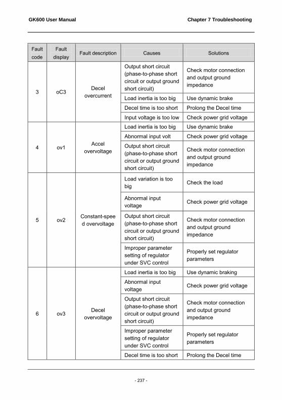
GK600 User Manual Chapter 7 Troubleshooting
- 237 -
Fault code
Fault display
Fault description Causes Solutions
3 oC3 Decel
overcurrent
Output short circuit (phase-to-phase short circuit or output ground short circuit)
Check motor connection and output ground impedance
Load inertia is too big Use dynamic brake
Decel time is too short Prolong the Decel time
Input voltage is too low Check power grid voltage
4 ov1 Accel
overvoltage
Load inertia is too big Use dynamic brake
Abnormal input volt Check power grid voltage
Output short circuit (phase-to-phase short circuit or output ground short circuit)
Check motor connection and output ground impedance
5 ov2 Constant-speed overvoltage
Load variation is too big
Check the load
Abnormal input voltage
Check power grid voltage
Output short circuit (phase-to-phase short circuit or output ground short circuit)
Check motor connection and output ground impedance
Improper parameter setting of regulator under SVC control
Properly set regulator parameters
6 ov3 Decel overvoltage
Load inertia is too big Use dynamic braking
Abnormal input voltage
Check power grid voltage
Output short circuit (phase-to-phase short circuit or output ground short circuit)
Check motor connection and output ground impedance
Improper parameter setting of regulator under SVC control
Properly set regulator parameters
Decel time is too short Prolong the Decel time

Chapter 7 Troubleshooting GK600 User Manual
- 238 -
Fault code
Fault display
Fault description Causes Solutions
7 FAL Module
protection
Overvoltage or overcurrent
Refer to the solutions of overvoltage or overcurrent
Output short circuit (phase-to-phase short circuit or output ground short circuit)
Check motor connection and output ground impedance
Loose connection of control board
Pull out and reinsert the cables of control board
Direct connection of inverter module
Seek services
Control board abnormal
Seek services
Switching power supply failed
Seek services
8 tUN Autotuning
failed
Bad motor connection Check motor connection
Autotuning during rotation of the motor
Autotuning in stationary status of the motor
Big error between real motor parameters and the setting
Set the parameters correctly according to motor nameplate
9 oL1 Drive
overloaded
Torque boost is too big under V/f control
Reduce torque boost value
Start FREQ is too high Drop start frequency
Accel/Decel time is too short
Prolong the Accel/Decel time
Motor parameters are improperly set
Set the parameters correctly according to motor nameplate
Output short circuit (phase-to-phase short circuit and output ground short circuit)
Check motor connection and output ground impedance
Load is too heavy Reduce the load
Inappropriate V/f curve under V/f control
Set V/f curve correctly
Restart the rotary motor
Reduce current limited value or flying start

GK600 User Manual Chapter 7 Troubleshooting
- 239 -
Fault code
Fault display
Fault description Causes Solutions
10 oL2 Motor
overloaded
Torque boost is too big under V/f control
Reduce torque boost value
Inappropriate V/f curve under V/f control
Set V/f curve correctly
Motor parameters are improperly set
Set the parameters correctly according to motor nameplate
Improper setting of motor overloaded protection time
Properly set the motor overloaded protection time
Motor stalled or sharp variation of load
Identify the causes of motor stalling or check the load condition
Long-time running of ordinary motor at low speed with heavy load
Select variable frequency motor
11 CtC Current
detection abnormal
Abnormal connection between control board and drive board
Check and re-connection
Abnormal current detection circuit of control board
Seek services
Abnormal current detection circuit of drive board
Seek services
Current sensor failed Seek services
SMPS failed Seek services
12 GdP Output ground
short-circuit protection
Output connection ground short circuit
Check motor connection and output ground impedance
Motor insulation abnormal
Check the motor
Inverter module abnormal Seek services
Output ground leakage current is too big
Seek services
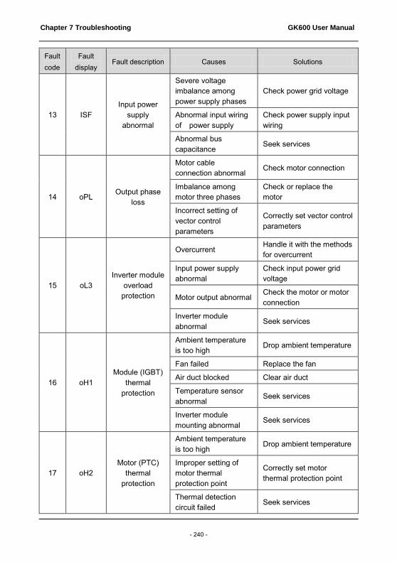
Chapter 7 Troubleshooting GK600 User Manual
- 240 -
Fault code
Fault display
Fault description Causes Solutions
13 ISF Input power
supply abnormal
Severe voltage imbalance among power supply phases
Check power grid voltage
Abnormal input wiring of power supply
Check power supply input wiring
Abnormal bus capacitance
Seek services
14 oPL Output phase
loss
Motor cable connection abnormal Check motor connection
Imbalance among motor three phases
Check or replace the motor
Incorrect setting of vector control parameters
Correctly set vector control parameters
15 oL3 Inverter module
overload protection
Overcurrent Handle it with the methods for overcurrent
Input power supply abnormal
Check input power grid voltage
Motor output abnormal Check the motor or motor connection
Inverter module abnormal
Seek services
16 oH1 Module (IGBT)
thermal protection
Ambient temperature is too high
Drop ambient temperature
Fan failed Replace the fan
Air duct blocked Clear air duct
Temperature sensor abnormal
Seek services
Inverter module mounting abnormal
Seek services
17 oH2 Motor (PTC)
thermal protection
Ambient temperature is too high
Drop ambient temperature
Improper setting of motor thermal protection point
Correctly set motor thermal protection point
Thermal detection circuit failed
Seek services

GK600 User Manual Chapter 7 Troubleshooting
- 241 -
Fault code
Fault display
Fault description Causes Solutions
18 oH3
Module temperature
detection disconnected
Temperature sensor not well connected with socket
Pull out and re-insert
Ambient temperature is too low
Raise ambient temperature
Module detection circuit failed
Seek services
Thermistor failed Seek services
20 EC1 Option board connection abnormal
Loose or poor option board connection Pull out and reinsert
Option board abnormal
Seek services
Control board abnormal
Seek services
22 dLC
Abnormal flat cable
connection of control board
Loose or poor drive line connection
Pull out and re-insert after complete power off
Drive board abnormal Seek services
Control board abnormal
Seek services
23 TEr
Function conflict
between analog
terminals
Analog input terminals are set to the same function
Do not set analog inputs to the same function
24 PEr External
equipment error
External fault terminal is enabled
Check the status of external fault terminal
Stall condition lasts too long
Check if the load is abnormal
26 to2 Consecutive
run time attained
"Consecutive run time attained" enabled
See specification of Group E0
27 to3 Cumulative run time attained
"Cumulative run time attained" enabled
See specification of Group E0
28 SUE Power supply
abnormal at run
DC bus voltage fluctuation is too big or the power is lost
Check input power grid voltage and load

Chapter 7 Troubleshooting GK600 User Manual
- 242 -
Fault code
Fault display
Fault description Causes Solutions
29 EPr EEPROM
read/write fault
Parameter read/write abnormal at control board
Seek services
30 CCL Contactor close
fault
Power supply voltage abnormal
Check grid power supply voltage
Abnormal contactor feedback circuit at drive board
Seek services
Contactor failed Seek services
Buffer resistance failed Seek services
Abnormal SMPS Seek services
31 TrC Port
communication abnormal
Improper setting of baud rate
Set properly
Communication port disconnected
Reconnected
Upper computer/device does not work
Make upper computer/device work
Drive communication parameter error Set properly
32 PdC Control panel
communication abnormal
Control panel disconnected
Reconnected
Severe EMI Check peripheral equipment or seek services
33 CPy Parameter copy failure
Parameter uploading or downloading abnormal
Seek services
No parameters stored at control panel
Seek services
35 SFt
Software version
compatibility failure
Version of control panel is not consistent with that of control board
Seek services
36 CPU Abnormal power loss
Abnormal power loss in last operation
RESET the fault
Faulty control board Seek services

GK600 User Manual Chapter 7 Troubleshooting
- 243 -
Fault code
Fault display
Fault description Causes Solutions
37 oCr Overcurrent benchmark
error
SMPS failed Seek services
Control board failed Seek services
38 SP1 5V supply out-of-limit
SMPS failed Seek services
Control board failed Seek services
39 SP2 10V supply out-of-limit
SMPS failed Seek services
Control board failed Seek services
40 AIP AI input
out-of-limit
Control board failed Seek services
AI input is too high or low
Set AI input within correct range
41 LoU Undervoltage protection
DC bus voltage is too low
Check input voltage if it is too low or the drive is the process of power loss
45 Plo PID feedback lost
Abnormal PID feedback channel abnormal
Check the feedback channel
Inappropriate setting of PID parameters
Set properly
46 PFS Abnormal Profibus
communication
Communication wiring problem Rewiring
Severe ambient EMI Check peripheral equipment or seek services
ATTENTION: When a fault occurs, please identify the causes and seek solutions according the guidance in the table. If the fault fails to be solved, do not apply power to the drive again. Contact the supplier for service in time.
Chapter 8 Maintenance GK600 User Manual
- 244 -
Chapter 8 Maintenance
Ambient temperature, humidity, salt mist, dust, vibration, aging and wear of internal components may result in drive faults. Routine maintenance shall be performed during the use and storage.
ATTENTION: Please make sure the power supply of the drive has been cut off, and DC bus voltage has discharged to 0V before the maintenance.
8.1 Routine Inspection
Please use the drive in the environment recommended by this manual, and perform routine inspection in accordance with the table below.
Inspection
items Inspection aspects
Inspection methods
Criteria
Operating environment
Temperature Thermometer -10℃~50℃
Humidity Hygrometer 5%~95%, condensation not allowed
Dust, oil stains, moisture and water-drop
Visual inspection
No filthy mud, oil stains and water drop
Vibration Observation Smooth running. No abnormal vibration
Gas Smell, visual inspection
No peculiar smell and abnormal smoke
Drive
Noise Listen No abnormal noise
Gas Smell, visual inspection
No peculiar smell and abnormal smoke
Appearance Visual inspection
No defect and deformation
Heat dissipation and temperature rise
Visual inspection
No dust and/or fiber particles in air duct, normal working of fans, normal air speed and volume, no abnormal temperature rise

GK600 User Manual Chapter 8 Maintenance
- 245 -
Inspection items
Inspection aspects Inspection methods
Criteria
Motor
Thermal status Smell No abnormal heating and scorching smell
Noise Listen No abnormal noise
Vibration Observe, listen
No abnormal vibration and sound
Running status
parameters
Power supply input current
Ammeter In the range of requirement
Power supply input voltage
Voltmeter In the range of requirement
Drive output current Ammeter In the range of requirement
Drive output voltage Voltmeter In the range of requirement
Temperature Thermometer
The difference between U0-33 displayed temperature and ambient temperature does not exceed 40℃
8.2 Regular Maintenance
Users should perform regular inspection of the drive every 3~6 months, so as to eliminate the potential faults.
ATTENTION:
Please make sure power supply of the drive has been cut off, and DC bus voltage has been discharged to 0V prior to maintenance.Never leave screws, gaskets, conductors, tools and other metal articles inside the drive. Failure to comply may result in equipment damage. Never modify the interior components of the drive in any condition. Failure to comply may result in equipment damage.
Inspection items Measures
Check if control terminal screws are loose Tighten
Check if main circuit terminal screws are loose Tighten
Check if ground terminal screws are loose Tighten
Check if copper bar screws are loose Tighten

Chapter 8 Maintenance GK600 User Manual
- 246 -
Inspection items Measures
Check if drive mounting screws are loose Tighten
Check if there are defect on power cables and control cables
Replace the cables
Check if there is dust on circuit board Clear it up
Check if air duct is blocked Clear it up
Check if drive insulation is failed
Test the ground terminal with 500V megameter after all input and output terminals are short-circuited via conductors. Ground test on individual terminals is strictly prohibited since this may cause damage to inverter.
Check if motor insulation is failed
Remove input terminals U/V/W of motor from drive and test the motor alone with 500V megameter. Failure to comply may result in drive failure.
Check if the storage period of the drive is over two years
Carry out power-on test, during which, the voltage should be boosted to rated value gradually using a voltage regulator; be sure to run at no load for more than 5 hours.
8.3 Replacement of Vulnerable Parts
Vulnerable parts of drive include cooling fan, electrolytic capacitor, relay or contactor etc. The service lives of these parts are subject to environment and working conditions. To maintain a favorable operating environment is conducive to improving the service life of parts and components; routine inspection and maintenance also contributes to effective improvement of parts' service life. To prolong the service life of entire drive, the cooling fan, electrolytic capacitor, relay or contactor and other vulnerable parts should be subjected to routine inspection according to the table below. Please replace the abnormal parts (if any) in time.

GK600 User Manual Chapter 8 Maintenance
- 247 -
Vulnerable parts
Service life Cause of damage Criteria
Fan 30,000~40,000h Wear of bearing and aging of blade
Check if fan blades have cracks Check if there is abnormal vibration and noise on working
Electrolytic capacitor
40,000~50,000h
Excessively high ambient temperature and excessively low air pressure result in electrolyte volatilization; aging of electrolyte capacitor
Check if there is liquid leakage Check if safety valve projects Check if capacitance value is out of allowable range Check if insulation resistance is abnormal
Relay/contactor
50,000~100,000 times
Corrosion and dust impairs the contacting effect of contact; excessively frequent contact action
Open/close failure False alarm of CCL fault
8.4 Storage
Storage environment should meet the requirements as set forth in the table below.
Items Requirements Recommended storage method and
environment
Storage temperature
-40~+70℃
In case of long-term storage, areas with an ambient temperature of less than 30℃ are recommended Avoid the storage in areas where temperature shock may result in condensation and freezing
Storage humidity
5~95% Product could be sealed with plastic film and desiccant
Storage environment
A space with low vibration and low content of salt where there is no direct exposure to sunlight, dust, no corrosive or flammable gas, oil stain, vapor and water drop
Product could be sealed with plastic film and desiccant

Chapter 8 Maintenance GK600 User Manual
- 248 -
ATTENTION: Since long-term storage may lead to the deterioration of electrolytic capacitor, the inverter must be powered up once in case storage period exceeds 2 years. After applying the power, input voltage must be boosted to rated value gradually using a voltage regulator, and be sure to have the inverter operated at no load for more than 5 hours.
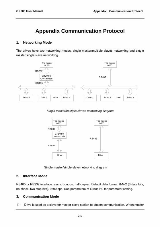
GK600 User Manual Appendix Communication Protocol
- 249 -
Appendix Communication Protocol
1. Networking Mode
The drives have two networking modes, single master/multiple slaves networking and single master/single slave networking.
Single master/multiple slaves networking diagram
Single master/single slave networking diagram
2. Interface Mode
RS485 or RS232 interface: asynchronous, half-duplex. Default data format: 8-N-2 (8 data bits, no check, two stop bits), 9600 bps. See parameters of Group H0 for parameter setting.
3. Communication Mode
1) Drive is used as a slave for master-slave station-to-station communication. When master
主机为
PC机
232/485转换模块
变频器
RS232
RS485
主机为PLC
变频器
RS485
主机为
PC机
232/485转换模块
变频器1 变频器2 ……
RS232
RS485
变频器n
主机为PLC
变频器1 变频器2 ……
RS485
变频器n
The master is PC The master
is PC
CNV- module
Drive 1 Drive 2 Drive n Drive n Drive 2 Drive 1
The master is PC The master
is PC
CNV- module
Drive Drive

Appendix Communication Protocol GK600 User Manual
- 250 -
sends commands using broadcast address, the slave does not respond; 2) Native address, baud rate and data format of inverter are set through slave operating
panel or serial communication; 3) Slave reports the current fault information in the latest response frame for master polling; 4) Drive employs RS-485 interface or extended RS-232 interface.
4. Protocol Format
Modbus protocol supports both RTU and ASCII mode. RTU data frame format is shown as the figure below:
RTU: In RTU mode, idle time between frames can be set through function code or comply with Modbus internal convention, for which the minimum interframe idle is as follows:
1) Frame header and end define the frame by making bus idle time equal to or longer than 3.5-byte time;
2) After the start of frame, the clearance between characters must be less than 1.5-character communication time, or the newly received characters will be treated as the header of the new frame;
3) Data check employs CRC-16 and the whole information participates in the check; the high and low bytes of check sum shall be sent after exchange. Please refer to examples at the end of protocol for details of CRC check;
4) The bus idle time of at least 3.5 characters (or set minimum bus idle time) shall be maintained between frames and needs not to accumulate the starting and ending idle time.
The data frame of which the request frame is "reading parameter value of b0-02 from slave 0x01" is as below:
Appendix Table 1
Address Function code Register address
Read words Check sum
01 03 02 02 00 01 24 72
Response frame of slave 0x01 is as below:
数据 校验功能码从机地址
起始:至少3.5个字符空闲
结束:至少3.5个字符空闲
Modbus报文
RTU数据帧格式RTU data frame format Modbus message
Start: at least 3.5 idle characters
Slave
address
Parameter Data Check End: at least 3.5 idle
characters

GK600 User Manual Appendix Communication Protocol
- 251 -
Appendix Table 2
Address Function code Register address
Read words Check sum
01 03 02 13 88 B5 12
ASCII: 1) Frame header is "0x3A" while the default frame end is "0x0D" "0x0A"; also, frame
end can be configured and defined by user; 2) In ASCII mode, all data bytes other than frame header and end are sent in the form
of ASCII code; high-4-bit byte and low-4-bit byte are sent successively; 3) In ASCII mode, the data is 7-bit long. For 'A'~'F', their uppercase ASCII codes are
used; 4) Data is subjected to LRC check which covers the information portion from slave
address to data; 5) Check sum is equal to the complement of sum of characters that participate in data
check (abort the feed bit). In ASCII mode, data frame format is as follows:
Examples of Modbus data frame in ASCII mode are as follows. The writing of 4000 (0xFA0) into internal register 02 02 of slave 0x01 is shown in the table below. LRC check = complement of (01+06+02+02+0x0F+0xA0) = 0x46
Appendix Table 3
Header Address Parameter Register address Write-in content LRC check End
Character : 0 1 0 6 0 2 0 2 0 F A 0 4 6 CR LF
ASCII 3A 30 31 30 36 30 32 30 32 30 46 41 30 34 36 0D 0A
Different response delays can be set for drive through parameters so as to adapt to specific application requirements of various master stations; in RTU mode, the actual response delay is not less than 3.5 characters, while in ASCII mode, the actual response delay shall not be less than 1ms.
数据 校验功能码从机地址起始:
“0x3A”结束:
“0xD,0xA”
Modbus报文
ASCII数据帧格式
Check
ASCII data frame format Modbus message
Start: "0 x 3A Slave
address Parameter Data End: 0xD,
0xA
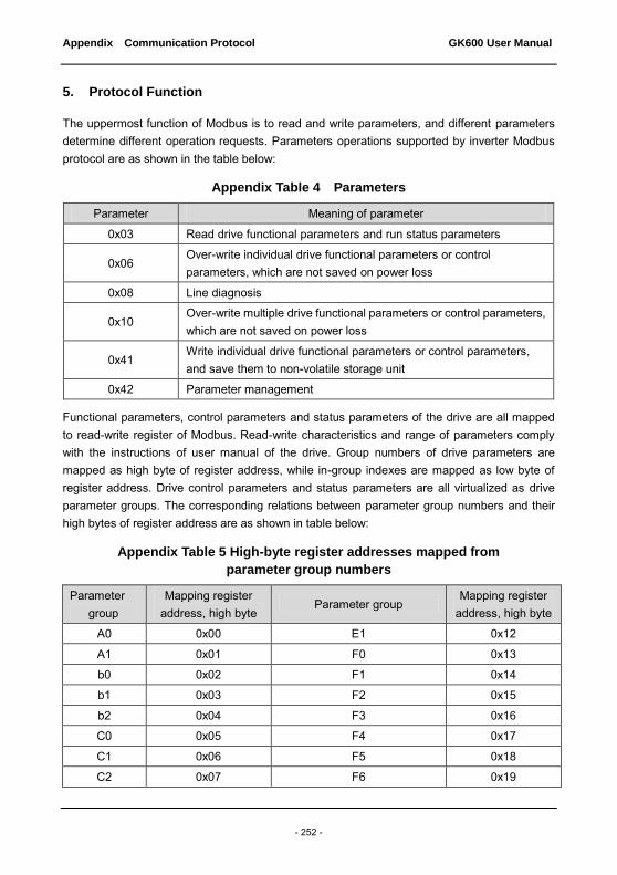
Appendix Communication Protocol GK600 User Manual
- 252 -
5. Protocol Function
The uppermost function of Modbus is to read and write parameters, and different parameters determine different operation requests. Parameters operations supported by inverter Modbus protocol are as shown in the table below:
Appendix Table 4 Parameters
Parameter Meaning of parameter
0x03 Read drive functional parameters and run status parameters
0x06 Over-write individual drive functional parameters or control parameters, which are not saved on power loss
0x08 Line diagnosis
0x10 Over-write multiple drive functional parameters or control parameters, which are not saved on power loss
0x41 Write individual drive functional parameters or control parameters, and save them to non-volatile storage unit
0x42 Parameter management
Functional parameters, control parameters and status parameters of the drive are all mapped to read-write register of Modbus. Read-write characteristics and range of parameters comply with the instructions of user manual of the drive. Group numbers of drive parameters are mapped as high byte of register address, while in-group indexes are mapped as low byte of register address. Drive control parameters and status parameters are all virtualized as drive parameter groups. The corresponding relations between parameter group numbers and their high bytes of register address are as shown in table below:
Appendix Table 5 High-byte register addresses mapped from
parameter group numbers
Parameter group
Mapping register address, high byte
Parameter group Mapping register
address, high byte
A0 0x00 E1 0x12
A1 0x01 F0 0x13
b0 0x02 F1 0x14
b1 0x03 F2 0x15
b2 0x04 F3 0x16
C0 0x05 F4 0x17
C1 0x06 F5 0x18
C2 0x07 F6 0x19

GK600 User Manual Appendix Communication Protocol
- 253 -
Parameter group
Mapping register address, high byte
Parameter group Mapping register
address, high byte
C3 0x08 H0 0x1A
C4 0x09 H1 0x1B
d0 0x0A H2 0x1C
d1 0x0B L0 0x1D
d2 0x0C L1 0x1E
d3 0x0D U0 0x1F
d4 0x0E U1 0x20
d5 0x0F U2 0x21 d6 0x10 Drive control parameter group 0x62 E0 0x11 Drive status parameter group 0x63
For example, the register address of drive parameter b0-02 is 0x0202 while that of E0-07 is 0x1107.
In the following paragraphs, we present the formats and meanings of Modbus protocol parameters and data portion hereafter, i.e. to introduce the "parameter" and "data" related contents in above-noted data frame format. These two parts constitute the application layer protocol data unit of Modbus. The application layer protocol data unit mentioned below refers to these two parts. We take RTU mode for example to describe frame format below. The length of application layer protocol data unit should be doubled in ACSII mode.
Application layer protocol data units of various parameters are as follows: Parameter 03: read register content Request format is shown in appendix table 6.
Appendix Table 6
Application layer protocol data unit
Data length (number of bytes)
Range
Parameter 1 0x03
Register address 2 0x0000~0xFFFF
Number of registers 12 0x0001~0x000C
Check LRC or CRC
Response format is shown in appendix table 7.

Appendix Communication Protocol GK600 User Manual
- 254 -
Appendix Table 7
Application layer protocol data unit
Data length (number of bytes)
Range
Parameter 1 0x03
Number of read bytes 1 2* number of registers
Register content 2* number of registers
Check LRC or CRC
Parameter 0x06(0x41): write register content (0x41 saved at power loss) Request format is shown in appendix table 8.
Appendix Table 8
Application layer protocol data unit
Data length (number of bytes)
Range
Parameter 1 0x06
Register address 2 0x0000~0xFFFF
Register content 2 0x0000~0xFFFF
Check LRC or CRC
Response format is shown in appendix table 9.
Appendix Table 9
Application layer protocol data unit
Data length (number of bytes)
Range
Parameter 1 0x06 Register address 2 0x0000~0xFFFF Register content 2 0x0000~0xFFFF
Check LRC or CRC
Some parameters of the drive are reserved and cannot be modified by communication setting. The list of these parameters is shown in appendix table 10.

GK600 User Manual Appendix Communication Protocol
- 255 -
Appendix Table 10
Parameters Remarks (Parameter identification) d0-22 d3-22 Communication not operable
(Parameter passing) A0-05 Communication not operable
(User password) A0-00
User password can not be set by communication, but the user password set by control panel can be unlocked by writing the same password from upper computer/device communication. Upper computer/device can view and modify parameters.
Parameter 0x08: communication line diagnosis. Request format is shown in appendix table 11.
Appendix Table 11
Application layer protocol data unit
Data length (number of bytes)
Range
Parameter 1 0x08
Sub-parameter 2 0x0000~0x0030
Data 2 0x0000~0xFFFF
Check LRC or CRC
Response format is shown in appendix table 12.
Appendix Table 12
Application layer protocol data unit
Data length (number of bytes)
Range
Parameter 1 0x08
Sub-parameter 2 0x0000~0x0030
Data 2 0x0000~0xFFFF
Check LRC or CRC
Sub-parameters supported by line diagnosis are as set forth in the table below.

Appendix Communication Protocol GK600 User Manual
- 256 -
Appendix Table 13 Line diagnosis sub-parameter
Sub-PARA Data
(request) Data
(response) Meaning of subfunction
0x0001 0x0000 0x0000
Reinitialize communication: make no-response mode disable.
0xFF00 0xFF00 Reinitialize communication: make no-response mode disable.
0x0003 “New frame
end” 00 “New frame
end” 00
Set the frame end of ASCII mode and this "new frame end" will replace the original line feed symbol.(Note: new frame end shall not be greater than 0x7F and shall not be equal to 0x3A)
0x0004 0x0000 No response
Set no-response mode. Only response to reinitialization communication request. This is mainly used for isolating faulty equipment.
0x0030 0x0000 0x0000
Make slave no-response to invalid command and error command
0x0001 0x0001 Make slave response to invalid command and error command
Parameter 0x10: write parameters continuously Request format is shown in appendix table 14.
Appendix Table 14
Application layer protocol data unit
Data length (number of bytes)
Range
Parameter 1 0x10
Register address 2 0x0000~0xFFFF
Number of registers 2 0x0001~0x0004
Number of bytes of register content
1 2* number of operation
registers
Register content 2* number of operation
registers
Check LRC or CRC
Response format is shown in appendix table 15.

GK600 User Manual Appendix Communication Protocol
- 257 -
Appendix Table 15
Application layer protocol data unit
Data length (number of bytes)
Range
Parameter 1 0x10
Register address 2 0x0000~0xFFFF
Number of registers 2 0x0001~0x0004
Check LRC or CRC
Parameter 0x42: parameter management Request format is shown in appendix table 16.
Appendix Table 16
Application layer protocol data unit
Data length (number of bytes)
Range
Parameter 1 0x42
Sub-parameter 2 0x0000~0x0007
Data
2 (high byte is parameter group number, while low
byte is parameter in-group index)
Check LRC or CRC
Response format is shown in appendix table 17.
Appendix Table 17
Application layer protocol data unit
Data length (number of bytes)
Range
Parameter 1 0x42
Sub-parameter 2 0x0000~0x0007
Data 2 0x0000~0xFFFF
Check LRC or CRC
Sub-parameters supported by parameter management are set forth in the table 18.

Appendix Communication Protocol GK600 User Manual
- 258 -
Appendix Table 18 Parameter management sub-parameters
Sub-PARA Data (request) Data (response) Meaning of subfunction
0x0000
Parameter group number and in-group index respectively possess high and low bytes
Upper limit of parameter Read the upper limit of parameter
0x0001
Parameter group number and in-group index respectively possess high and low bytes
Lower limit of parameter Read the lower limit of parameter
0x0002
Parameter group number and in-group index respectively possess high and low bytes
See specification below for details of parameter characteristics
Read the characteristics of parameter
0x0003 Parameter group number possesses high byte, while the lower byte is 0.
Maximum value of in-group index
Read the maximum value of in-group index
0x0004 Parameter group number possesses high byte, while the lower byte is 0.
The next parameter group number possesses high byte, while the lower byte is 0.
Read the next parameter group number
0x0005 Parameter group number possesses high byte, while the lower byte is 0.
The previous parameter group number possesses high byte, while the lower byte is 0.
Read the previous parameter group number
Status parameter group should not be modified and does not support the reading of upper and lower limits. Parameter characteristic is 2-byte long, and the bit definition is shown in the table below:
Appendix Table 19 Parameter characteristics
Characteristic parameter (BIT)
Value Meaning
BIT1~BIT0
00B Changeable in run
01B Not changeable in run, but changeable in stop
10B Read only

GK600 User Manual Appendix Communication Protocol
- 259 -
Characteristic parameter (BIT)
Value Meaning
11B Factory parameters
BIT4~BIT2
000B Accuracy: 1
001B Accuracy: 0.1
010B Accuracy: 0.01
011B Accuracy: 0.001
100B Accuracy: 0.0001
Others Reserved
BIT7~BIT5
000B The unit is A
001B The unit is Hz
010B The unit is Ω
011B The unit is r/min
100B The unit is S
101B The unit is V
110B The unit is %
111B No unit
BIT8 0: decimal; 1: hexadecimal Display format
BIT9 0: non-quick menu; 1: quick menu Quick menu or not
BIT10 0: not uploaded; 1: uploaded Uploaded to control panel or not
BIT13~BIT11
001B Data width: 1
010B Data width: 2
011B Data width: 3
100B Data width: 4
101B Data width: 5
110B Data width: 6
111B Data width: 7
BIT14 Number of symbols available/not
available 0: unsigned number; 1: directed number
BIT15 Reserved Reserved
The response format is shown as table 20 when an error occurs.
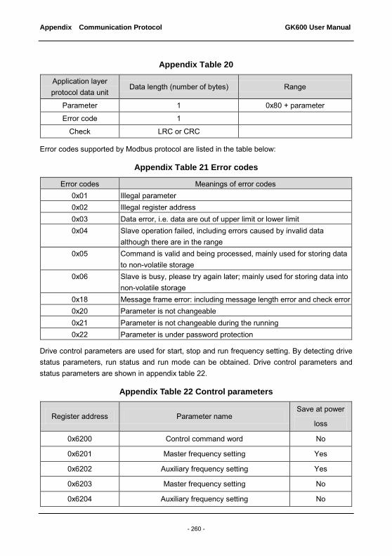
Appendix Communication Protocol GK600 User Manual
- 260 -
Appendix Table 20
Application layer protocol data unit
Data length (number of bytes) Range
Parameter 1 0x80 + parameter
Error code 1
Check LRC or CRC
Error codes supported by Modbus protocol are listed in the table below:
Appendix Table 21 Error codes
Error codes Meanings of error codes 0x01 Illegal parameter 0x02 Illegal register address 0x03 Data error, i.e. data are out of upper limit or lower limit 0x04 Slave operation failed, including errors caused by invalid data
although there are in the range 0x05 Command is valid and being processed, mainly used for storing data
to non-volatile storage 0x06 Slave is busy, please try again later; mainly used for storing data into
non-volatile storage 0x18 Message frame error: including message length error and check error 0x20 Parameter is not changeable 0x21 Parameter is not changeable during the running 0x22 Parameter is under password protection
Drive control parameters are used for start, stop and run frequency setting. By detecting drive status parameters, run status and run mode can be obtained. Drive control parameters and status parameters are shown in appendix table 22.
Appendix Table 22 Control parameters
Register address Parameter name Save at power
loss
0x6200 Control command word No
0x6201 Master frequency setting Yes
0x6202 Auxiliary frequency setting Yes
0x6203 Master frequency setting No
0x6204 Auxiliary frequency setting No
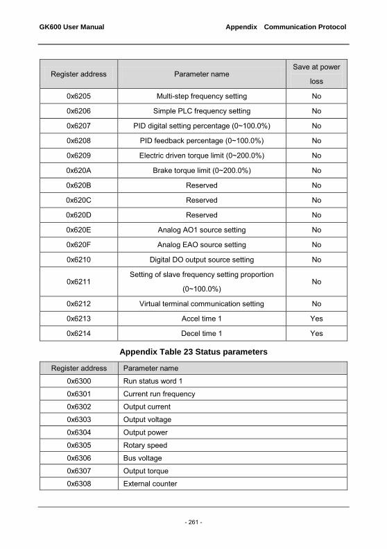
GK600 User Manual Appendix Communication Protocol
- 261 -
Register address Parameter name Save at power
loss
0x6205 Multi-step frequency setting No
0x6206 Simple PLC frequency setting No
0x6207 PID digital setting percentage (0~100.0%) No
0x6208 PID feedback percentage (0~100.0%) No
0x6209 Electric driven torque limit (0~200.0%) No
0x620A Brake torque limit (0~200.0%) No
0x620B Reserved No
0x620C Reserved No
0x620D Reserved No
0x620E Analog AO1 source setting No
0x620F Analog EAO source setting No
0x6210 Digital DO output source setting No
0x6211 Setting of slave frequency setting proportion
(0~100.0%) No
0x6212 Virtual terminal communication setting No
0x6213 Accel time 1 Yes
0x6214 Decel time 1 Yes
Appendix Table 23 Status parameters
Register address Parameter name
0x6300 Run status word 1
0x6301 Current run frequency
0x6302 Output current
0x6303 Output voltage
0x6304 Output power
0x6305 Rotary speed
0x6306 Bus voltage
0x6307 Output torque
0x6308 External counter

Appendix Communication Protocol GK600 User Manual
- 262 -
Register address Parameter name
0x6309 High-bit words of actual length
0x630A Low-bit words of actual length
0x630B Status of digital input terminal
0x630C Status of digital output terminal
0x630D Setting of run frequency
0x630E PID setting
0x630F PID feedback
0x6310 Set length
0x6311 Set Accel time 1
0x6312 Set Decel time 1
0x6313 AI1 (unit: V)
0x6314 AI2 (unit: V) (Negative value indicates the corresponding digital complement)
0x6315 EAI (unit: V)
0x6316 DI (unit: kHz)
0x6317 Fault 1
0x6318 Fault 2
0x6319 Fault 3 (the latest)
0x631A Run display parameter
0x631B Stop display parameter
0x631C Setting of drive control mode
0x631D Frequency setting mode
0x631E Master frequency setting
0x631F Digital setting of master frequency
0x6320 Auxiliary frequency setting
0x6321 Digital setting of auxiliary frequency
0x6322 Drive status word 2
0x6323 Current fault of the drive
Drive control bits are defined as below table 24.
Appendix Table 24 Control bits
Control bit Value Meaning Function description
BIT0 0 Run command disabled Stop the drive
1 Run command enabled Start the drive

GK600 User Manual Appendix Communication Protocol
- 263 -
Control bit Value Meaning Function description
BIT1 1 Reverse Set the run direction
when run command enabled 0 Forward
BIT2 1 Jog
0 Jog disabled
BIT3 1 Reset command enabled
0 Reset command disabled
BIT4 1 Coast to stop enabled
0 Coast to stop disabled
BIT15~BIT5 000000B Reserved
ATTENTION: When BIT0 and BIT2 coexist, jog takes precedence.
Drive status bits are shown in appendix table 25.
Appendix Table 25 Status word 1 bits
Status bit Value Meaning Remarks
BIT0 1 Run
0 Stop
BIT1 1 Reverse
0 Forward
BIT3~BIT2
00B Constant speed
01B Accel
10B Decel
BIT4 0
Main setting not attained
1 Main setting attained
BIT7~BIT5 Reserved
BIT15~BIT8 0x00~0xFF Fault code
0: drive normal. Non-0: drive at fault; Refer to relative specification of the fault codes in Chapter 7 in this user manual

Appendix Communication Protocol GK600 User Manual
- 264 -
Appendix Table 26 Status word 2 bits
Status bit Value Meaning Remarks
BIT0 1 Jog
0 Non-jog
BIT1 1 PID run
0 Non-PID run
BIT2 1 PLC run
0 Non-PLC run
BIT3 1
Run at multi-step frequency
0 Run at non-multi step
frequency
BIT4 1 Ordinary run
0 Non-ordinary run
BIT5 1 Wobble frequency
0 Non-wobble frequency
BIT6 1 Undervoltage
0 Normal voltage
BIT7 1
Sensor-less vector control
0 Non-sensor-less vector
control
BIT8 0 Reserved
BIT9 0 Reserved
BIT10 1 Autotuning
0 Non-autotuning
Others 0 Reserved
6. Operation Instructions
0x03 reads multiple (including one) registers (default address is 0x01). Master enquiry:

GK600 User Manual Appendix Communication Protocol
- 265 -
Appendix Table 27
Address Parameter Register address
Number of registers
Check code
01 03 XX XX 000X XX XX
Slave response:
Appendix Table 28
Address Parameter Total number of bytes
Data Check code
01 03 2* number of registers
Bn~B0 XX XX
Register address: 0x00 00~0x63 22; Number of registers: 0x00 01~0x00 0C; Data: n is equal to (2 x the number of registers -1). Application example: Note: before using communication controlling drive, please check if hardware is properly connected; in addition, be sure to properly set the communication data format, baud rate and address. Parameter 0x03 is used here to read values of 0x01 slave's control parameters b0-00, b0-01, b0-02 and b0-03. At this moment, b0-00 = 0, b0-01 = 0, b0-02 = 50.00, b0-03 = 0.
Appendix Table 29
Address PARAM Register address
Number of registers
Number of data bytes
Data Check sum
Request 01 03 02 00 00 04 None None 44 B1
Response 01 03 None None 08 0000,0000, 1388, 0000
11 79
Management of parameter 42H Master enquiry:
Appendix Table 30
Address Parameter Sub-parameter Data Check code
01 42 XX XX XX XX XX XX
Slave response:

Appendix Communication Protocol GK600 User Manual
- 266 -
Appendix Table 31
Address Parameter Sub-parameter Data Check code
01 42 XX XX B1~B0 XX XX
Register address: 0x00 00~0x21 06 and 0x62 00~0x63 22.
Sub-parameter: refer to the table of parameter managing sub-parameter. Data: refer to the values of data as set forth in the table of parameter managing sub-parameter. Example: Parameter 0x42 is used here to read the upper limit value of 0x01 slave's control parameter b0-02 which is 600.00:
Appendix Table 32
Address Parameter Sub-PARA Data Check sum
Request 01 42 00 00 02 02 F9 64
Response 01 42 00 00 EA 60 36 8D
0x06 (0x41 data storage) writes that individual parameter data is not saved. Master enquiry:
Appendix Table 33
Address Parameter Register address
Data Check code
01 06 62 00 B1 B0 XX XX
Slave response:
Appendix Table 34
Address Parameter Register address
Data Check code
01 06 62 00 B1 B0 XX XX
Example: Parameter 0x06 is used here to write 0x01 slave's control command (forward), i.e. to write 1 to register address 0x6200:
Appendix Table 35
Address Parameter Register address
Number of registers
Number of data bytes
Data Check sum
Request 01 06 62 00 None None 00 01 57 B2
Response 01 06 62 00 None None 00 01 57 B2

GK600 User Manual Appendix Communication Protocol
- 267 -
10H writes that the data of multiple registers are not saved. Master enquiry:
Appendix Table 36
Address Parameter Register address
Number of registers
Number of data bytes
Data Check code
01 10 XX XX 0001~0004 Number of 2* registers
XX XX XX XX
Slave response:
Appendix Table 37
Address Parameter Register address Number of registers
Check code
01 10 XX XX Number of 2*
registers XX XX
Register address: 0x00 00~0x1E 04, 0x62 00~0x62 14 Number of registers: 0x00 01~0x00 04 Number of data bytes: 0x02~0x08 Data: n is equal to (2 x the number of registers -1).
Example: Parameter 0x10 is used here to write the corresponding write data 1, 6 and 0 in control registers 0x6200, 0x6201 and 0x6202 of slave 0x01:
Appendix Table 38
Address Parameter Register address
Number of registers
Number of data bytes
Data Check sum
Request 01 10 62 00 00 03 06 0001,0006,0000 CE F8
Response 01 10 62 00 00 03 None None 9F B0
08H: communication line diagnosis Master enquiry:
Appendix Table 39
Address Parameter Sub-parameter Data Check code
01 08 XX XX XX XX XX XX
Slave response:
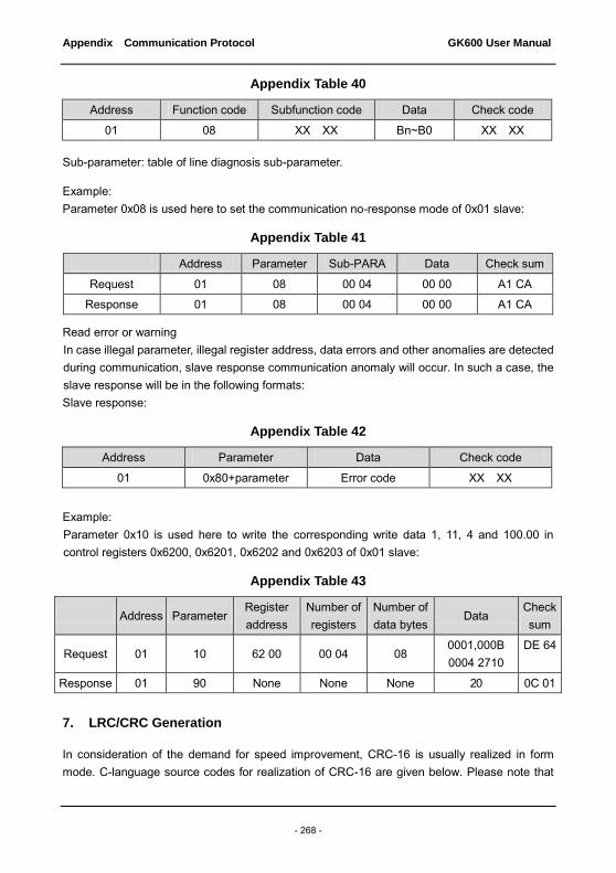
Appendix Communication Protocol GK600 User Manual
- 268 -
Appendix Table 40
Address Function code Subfunction code Data Check code
01 08 XX XX Bn~B0 XX XX
Sub-parameter: table of line diagnosis sub-parameter.
Example: Parameter 0x08 is used here to set the communication no-response mode of 0x01 slave:
Appendix Table 41
Address Parameter Sub-PARA Data Check sum
Request 01 08 00 04 00 00 A1 CA
Response 01 08 00 04 00 00 A1 CA
Read error or warning In case illegal parameter, illegal register address, data errors and other anomalies are detected during communication, slave response communication anomaly will occur. In such a case, the slave response will be in the following formats: Slave response:
Appendix Table 42
Address Parameter Data Check code
01 0x80+parameter Error code XX XX
Example: Parameter 0x10 is used here to write the corresponding write data 1, 11, 4 and 100.00 in control registers 0x6200, 0x6201, 0x6202 and 0x6203 of 0x01 slave:
Appendix Table 43
Address Parameter Register address
Number of registers
Number of data bytes
Data Check sum
Request 01 10 62 00 00 04 08 0001,000B 0004 2710
DE 64
Response 01 90 None None None 20 0C 01
7. LRC/CRC Generation
In consideration of the demand for speed improvement, CRC-16 is usually realized in form mode. C-language source codes for realization of CRC-16 are given below. Please note that

GK600 User Manual Appendix Communication Protocol
- 269 -
the high and low bytes have been exchanged in final result, that is to say, the result is the CRC check sum to be sent:
/* The function of CRC16*/ Uint16 CRC16(const Uint16 *data, Uint16 len) { Uint16 crcValue = 0xffff; Uint16 i; while (len--) { crcValue ^= *data++; for (i = 0; i <= 7; i++) { if (crcValue & 0x0001) { crcValue = (crcValue >> 1) ^ 0xa001; } else { crcValue = crcValue >> 1; } } } return (crcValue); }