Embed Size (px)
Citation preview

�
This document presents the Executive Summary, the first of six volumes comprising the 2006 Baseline Technical Report (BTR) for the international FAIR project (Facility for Antiproton and Ion Research). The BTR provides the technical description, cost, schedule, and assessments of risk for the proposed new facility. The purpose of the BTR is to provide a reliable basis for the construction, commissioning and operation of FAIR. It is, in this sense, primarily a technical document. The science case for the various areas of research to be performed at FAIR is summarized in the introductions to the respective Volumes 3 to 5 of the BTR describing the experimental facilities. For additional information and discussion, we refer to the original Conceptual Design Report (CDR) and a series of subsequent collaboration workshops and papers to be found at the FAIR website (http://www.gsi.de/fair).
The BTR is one of the central documents requested by the FAIR International Steering Committee (ISC) and its working groups, in order to prepare the legal process and the decisions on the construction and operation of FAIR in an international framework. It provides the technical basis for legal contracts on contributions to be made by, so far, 13 countries within the international FAIR Consortium. The International Steering Committee as well as its working groups have been established under the umbrella of a Memorandum of Understanding for the preparatory phase of FAIR, signed by representatives from the 13 countries.
The BTR begins with this extended Executive Summary as Volume 1, which is also intended for use as a stand-alone document. The Executive Summary provides brief summaries of the accelerator facilities (BTR Volume 2), the scientific programs and experimental stations (BTR Volumes 3-5), civil construction and safety (BTR Volume 6), and of the work-project structure, costs and schedule. For the latter, more details are laid down in the Cost Book, a document separate from the BTR with restricted and controlled distribution. These technical documents, BTR and Cost Book, were prepared from contributions by the various experiment collaborations and the FAIR accelerator team, under the guidance of the Working Group on Scientific and Technical Issues (STI) and its subcommittees. The respective authors of the various contributions are listed in the respective BTR volumes and at the end of this Executive Summary. Seperate documents describe the management structure and legal framework. The latter documents are under preparation by the FAIR International Steering Committee and its Working Groups on Administrative and Financial Issues (AFI).
The appendix to the present Executive Summary lists i. the 13 countries and their respective representatives that have signed the FAIR Memorandum of Understanding; ii. the representatives from the 13 countries of the International Steering Committee (ISC), and iii. the members of its Working Groups on Scientific and Technical Issues (STI), on Administrative and Financial Issues (AFI), and of the sub-committees to these working groups. iv. the lists of authors of the various experimental proposals and their institutional affiliations.
Preface
Executive Summary

�
FAIR Baseline Technical Report
Volume 1 Executive Summary (this Report)
available on CD (attached to the inside of the back of this Report)
Volume 1 Executive Summary
Volume 2 Accelerator and Scientific Infrastructure
Volume 3A Experiment Proposals on QCD Physics
3.1 CBM - Compressed Baryonic Matter Experiment
Volume 3B Experiment Proposals on QCD Physics
3.2 PANDA - Strong Interaction Studies with Antiprotons 3.3 PAX - Antiproton/Proton Scattering Experiments with Polarization 3.4 ASSIA- Spin-dependent Interactions with Antiprotons
Volume 4 Experiment Proposals on Nuclear Structure and Astro Physics (NUSTAR)
4.1 LEB-SuperFRS - Low-Energy Branch of the Super-FRS 4.2 HISPEC/DESPEC - High Resolution In-Flight and Decay Spectroscopy 4.3 MATS - Precision Measurements of Very Short-Lived Nuclei Using an Advanced Trapping System for Highly-Charged Ions 4.4 LASPEC - Laser Spectroscopy of Radioactive Isotopes and Isomers 4.5 R3B - Reactions with Relativistic Radioactive Beams 4.6 ILIMA - Isomeric Beams, Lifetimes and Masses 4.7 AIC - Antiptoton-Ion Collider 4.8 ELISe - Electron-Ion Scattering 4.9 EXL - Exotic Nuclei in Light-Ion Induced Reactions
Volume 5 Experiment Proposals on Atomic, Plasma and Applied Physics (APPA)
5.1 SPARC – Atomic Physics with Stored High Energy Ion Beams 5.2 HEDgeHOB - High Energy Dense Matter Generated by Heavy Ion Beams 5.3 WDM - Radiative Properties of Warm Dense Matter 5.4 FLAIR - Facility for Low-Energy Antiproton and Ion Research 5.5 BIOMAT - High-Energy Irradiation Facility for Biophysics and Materials Research
Volume 6 Civil Construction and Safety
Volumes 2 to 6 are not available in print
http://www.gsi.de/fair/reports/btr.html
FAIR Baseline Technical Report

�
FAIRBaseline Technical Report
Executive Summary
Editors H. H. Gutbrod (Editor in Chief)
I. Augustin, H. Eickhoff, K.-D. Groß, W. F. Henning, D. Krämer, G. Walter
September 2006
ISBN 3-9811298-0-6 EAN 978-3-9811298-0-9
Facility for Antiproton and Ion Research
Executive Summary

Preface 1
1. Introduction 6
2. FAIR Accelerator Facility 9
2.1 Overview 9 2.2 FAIR Performance Requirements and Basic Facility Concept 10 2.3 Technical Description of the FAIR Accelerator Facility 11 2.4 Modifications to the Conceptual Design Report 12 2.5 Parallel Operation and Synergy 13 2.6 Technological Challenges 14
3. Experimental Programs and Collaborations 15
3.1 Overview 15 3.2 Nuclear Structure, Astrophysics and Reactions with Rare-Isotope-Beams - the NUSTAR Collaboration 18 3.2.1 Physics Case 18 3.2.2 The Rare-Isotope-Beam Facility at FAIR 19 3.2.3 Experiments at the Rare-Isotope-Beam Facility 21 3.3 Hadron Physics with Antiproton Beams - the PANDA Collaboration 22 3.3.1 Physics Motivation 22 3.3.2 Research Program 22 3.3.3 Instrumentation and Detector 24 3.3.4 Interaction Region 24 3.3.5 Target Spectrometer 25 3.3.6 Forward Spectrometer 26 3.3.7 Data Acquisition and Trigger 26 3.4 The Phase Diagram of Strongly Interacting Matter - the CBM Collaboration 27 3.4.1 Exploring the QCD Phase Diagram with Heavy-ion Collisions 27 3.4.2 The Scientific Goals of the CBM Experiment 29 3.4.3 The CBM Detector Concept 29 3.4.4 Feasibility and Performance Studies 30 3.5 High Energy Density Bulk Matter Generated with Intense Heavy Ion and Laser Beams - the HEDgeHOB and the WDM Collaboration 31 3.5.1 Physics Motivation 31 3.5.2 Research Program 31 3.5.3 Instrumentation at FAIR 32 3.6 Atomic and Fundamental Physics with Highly Charged Ions and Antiprotons - the SPARC and the FLAIR Collaborations 33 3.6.1 Atomic Physics with Highly Charged Ions 33 3.6.2 Instrumentation for SPARC 33 3.6.3 Physics with Low-Energy Antiprotons 34 3.6.4 The FLAIR Facility 35 3.7 High-Energy Irradiation Facility for Biophysics and Materials Research - the BIOMAT Collaboration 36 3.7.1 Science Case 36 3.7.2 The BIOMAT Irradiation Facility 37 3.8 Offline Computing for FAIR Experiments 38
Executive Summary – Table of Contents
FAIR Baseline Technical Report

�
4. Civil Engineering 39
5. Radiation Safety Aspects 41
5.1 Radiation Safety Requirements 41 5.2 The Radiation Shielding Plan for FAIR 42 5.3 Radiation Protection Concerning the Emission of Radio-Nuclides 42
6. Organisation of FAIR as International Project 43
6.1 International Steering Committee (ISC) 43 6.2 Working Group on Scientific and Technical Issues (STI) 43 6.3 Working Group on Administrative and Funding Issues (AFI) 45
7. Costs and Schedule 49
7.1 Overview 49 7.2 Costs of the Accelerator Complex 50 7.3 Civil Construction Costs for Accelerator and Experimental Buildings 50 7.4 Costs of the Construction of the Experiments 50 7.5 Total Contruction Cost 51 7.6 Schedule 53 7.7 Critical Path 53 7.8 Manpower - Resource Loaded Schedule 55 7.9 Budgetary Aspects 55 7.9.1 Spending Profile 55 7.9.2 Risk budget 56 7.10 Commissioning 56 7.10.1 Start of commissioning 56 7.10.2 End of Commissioning 57 7.11 Operation 57
8. Conclusion and Outlook 61
9. Appendix 63
Executive Summary

�
In 2001, GSI, together with a large international science community, presented a Conceptual Design Report (CDR) for a major new accelerator facility for beams of ions and antiprotons in Darmstadt. The concept for the new facility, now named FAIR (Facility for Antiproton and Ion Research), was based on extensive discussions and a broad range of workshops and working group reports, organized by GSI and by the international user communities over a period of several years. It also adopted priority recommendations, independently made by high level science committees, both national and international, on fields of science addressed by the proposed new facility.
Subsequent to an in-depth evaluation of the proposal by the German Wissenschaftsrat (the highest-level science advisory committee to the German government) and its recommendation to realize the facility, the Federal Government gave conditional approval for construction of FAIR in February 2003. The approval was contingent upon the following conditions. (i) a scientific-technical plan for a staged construction, and (ii) participation of international partners contributing at least 25 % to the construction cost.
Since then the project has gone through several major stages of development and significant progress has been achieved with regard to the scientific-technical and the political preparation of the project. This Baseline-Technical Report (BTR) for FAIR is an important result of this process and progress.
The scientific-technical and the science-political processes have been closely linked to each other. To steer and coordinate all preparatory activities, an international committee structure, led by the International Steering Committee (FAIR-ISC), was established for FAIR with representatives of ministries or funding agencies from, so far, 13 countries: China, Finland, France, Germany, Greece, India, Italy, Poland, Romania, Russia, Spain, Sweden, and United Kingdom. These countries have signed a Memorandum of Understanding for FAIR which provides the framework for scientific-technical cooperation during the preparatory period 2004-2006 and expresses the explicit intent of the members to participate in the construction and science use of FAIR.
In order to prepare the construction of FAIR with international cooperation, the members of the ISC agreed that a set of documents should be developed by spring 2006, on scientific and technical issues on the one hand and on administrative and funding issues on the other.
These documents provide the basis for a decision on the construction and operation of FAIR in an international legal framework and for contracts on contributions to be made by the partner countries. The BTR is one of these documents. It provides the technical description, cost, schedule, organizational structure, and assessment(s) of risk for the international FAIR project. The purpose of the BTR is to provide a reliable basis for the construction, commissioning and operation of the proposed facility and for its science use.
The ISC has formed two working groups, the Working Group for Scientific and Technical Issues (STI) and the Working Group on Administrative and Funding Issues (AFI). These working groups formed several sub-groups and sub-committees: scientific, technical and administrative advisory committees with expertise regarding the proposed research programs, the facility design, cost and legal issues, etc. (for details see Chapter 6). Based on this committee and sub-committee structure the specific mandate of the STI Working Group included:
• Definition of the scientific program: In a letter- of-intent and subsequent technical proposal process (during 2004/2005) STI, with the help of program advisory committees (PACs), evaluated and rated the proposed research programs and experimental facilities. Resulting from this comprehensive evaluation process, STI worked out a detailed plan defining the experiments which should be part of base programs and be included into the core facility funding. The BTR describes these experiments.
• Definition of the layout and technical design of the FAIR accelerator facilities: In parallel to the scientific review, the proposed accelerator facility was technically evaluated with the help of a Technical Advisory Committee (TAC) and expert sub-groups, taking into account also proposed modifications and additions to the original design that were made in order to optimize operation and accommodate further programs. Resulting from this evaluation process, beam specifications of certain accelerator rings were modified and the topological layout of the facility was considerably re-designed. The BTR describes this re-designed facility lay-out, its technical components and its performance characteristics.
• Determination of costs and schedule for the construction and operation of FAIR: After setting up a general costing scheme (which was defined
1. Introduction
FAIR Baseline Technical Report

�
by the AFI working group and its expert sub-panel on Full Costing Issues, FCI), STI, assisted by two cost review panels, evaluated the costs for the accelerator and experimental facilities, as well as for civil construction. It also reviewed the operation costs for the facility. The detailed results on costs and schedule are specified in the Cost Book which was prepared together with this BTR (with restricted and controlled distribution).
The specific mandate of the AFI Working Group and its sub-committees included:
• Development of, and recommendations on, an adequate legal structure of FAIR: According to the present considerations, FAIR will be organized as a limited liability company based on German law (GmbH, "Gesellschaft mit beschränkter Haftung"). The Fair GmbH is supposed to cooperate closely with GSI for construction and operation of the FAIR facility (on a contractual basis as will be the case with all other participating institutions). In this way, optimal use shall be made of the know-how and experience existing at GSI and other partner laboratories.
Further details will be stipulated in the Convention, Articles of Association, and the By-Laws under which FAIR will be set up.
• Preparation of legal contracts for contributions to be made by the partner countries: draft versions for these contracts have been developed by the AFI Working Group and the ISC, to be presented to the respective governmental authorities in the partner countries.
In parallel to the preparatory activities coordinated by the FAIR committees, research and development for the FAIR accelerator and experimental facilities has considerably advanced. About 2500 scientists and engineers have been involved as authors in the preparation of the scientific and technical documents for FAIR. Particular emphasis on the accelerator side is on fast-cycling, super-conducting magnets; ultra-high vacuum aspects for low charge-state operation; high-current beam operation and control; and on fast stochastic and (high-energy) electron cooling. Significant progress has been achieved and the principal feasibility of the proposed technical approaches have been demonstrated. Prototyping for
Figure 1.1: Artists view of FAIR. The synchrotrons on the right will be located 10 to 13 m underground and will not be visible in reality. Most of the roofs will be vegetated and thus most of the facility will be hidden from view.
Executive Summary

�
superconducting magnets has started. The same holds for research and development towards the experiments planned at FAIR.
The legal procedures and technical planning associated with civil construction has also progressed. As a major step forward, the development plan for FAIR was recently formally approved by the Darmstadt City Council and the regional (district) authorities of the State of Hessen. Moreover, civil construction planning has been finalized taking into account the modified topology of the accelerators and experiments. Fig. 1.1 shows an artistic expression of th FAIR facility. The location of the facility can be seen in the regional map (Fig. 1.2).
The results presented in the BTR have been worked out in close collaboration between the international science community and the GSI Laboratory. They reflect the collective work of the FAIR community performed over the last 5 years since the publication of the FAIR CDR. About 2500 scientists and engineers from 45 countries have contributed to the progress and co-authored this BTR. They are listed individually in this Report, in the various technical proposals for experiments as well as in the technical reports for the accelerator work packages and technical infrastructures, and underline the broad involvement of the international research community in the preparations for FAIR.
Frankfurt
FAIR
State of
Hessen
Darmstadt
Figure 1.2: The regional map shows the location of the FAIR facility in the State of Hessen in Germany.
FAIR Baseline Technical Report

�
2.1 Overview
The concept of the FAIR Accelerator Facility has been developed by the international science community and the GSI Laboratory. It aims for a multifaceted forefront science program, beams of stable and unstable nuclei as well as antiprotons in a wide range of intensities and energies, with optimum beam qualities.
The concept builds and substantially expands on seminal developments made over the last 15 years at GSI and at other accelerator laboratories worldwide in the acceleration, accumulation, storage and phase space cooling of high-energy proton and heavy-ion beams. Based on that experience and adopting new developments, e.g. in fast cycling superconducting magnet design, in stochastic and in high-energy electron
cooling of ion beams, and also in ultra-high vacuum technology, a first conceptual layout of the new facility was proposed in 2001. Since then, the layout published in the Conceptual Design Report has undergone several modifications in order to accommodate additional scientific programs and optimize the layout, but also to reduce costs and to minimize the ecological impact of the project.
The present layout is shown in Fig. 2.1. A super-conducting double-synchrotron SIS100/300 with a circumference of 1,100 meters and with magnetic rigidities of 100 and 300 Tm, respectively, is at the heart of the FAIR accelerator facility. Following an upgrade for high intensities, the existing GSI accelerators UNILAC and SIS18 will serve as an injector.
2. FAIR Accelerator Facility
Figure 2.1: Layout of the existing GSI facility (UNILAC, SIS18, ESR) on the left and the planned FAIR facility on the right: the supercon-ducting synchrotrons SIS100 and SIS300, the collector ring CR, the accumulator ring RESR, the new experimental storage ring NESR, the rare isotope production target, the superconducting fragment separator Super-FRS, the proton linac, the antiproton production target, and the high energy antiproton storage ring HESR. Also shown are the experimental stations for plasma physics, relativistic nuclear collisions (CBM), radioactive ion beams (Super-FRS), atomic physics, and low-energy antiproton and ion physics (FLAIR).
Rare Isotope Production Target
Antiproton Production Target
Executive Summary

�0
Adjacent to the large double- synchrotron is a complex system of storage-cooler rings and experiment stations, including a superconducting nuclear fragment separator (Super-FRS) and an antiproton production target. FAIR will supply rare isotope beams (RIBs) and antiproton beams with unprecedented intensity and quality. Moreover, the facility is designed to provide particle energies 20-fold higher compared to those achieved so far at GSI.
An important feature of the FAIR accelerator facility is that, due to the intrinsic cycle times of the accelerator and storage-cooler rings, up to four research programs can be run in a truly parallel mode. This allows, in a very efficient and cost-effective way, a rich and multidisciplinary research program, covering the fields: QCD studies with cooled beams of antiprotons, nucleus-nucleus collisions at highest baryon density, nuclear structure and nuclear astrophysics investigations with nuclei far off stability, high density plasma physics, atomic and material science studies, radio-biological and other application-oriented studies.
2.2 FAIR Performance Requirements and Basic Facility Concept
The concept and design of the FAIR accelerator facility were derived from the following requirements set by the planned scientific programs:
Beams of all ion species plus antiprotons: FAIR is expected to provide beams of all ion species, from hydrogen to uranium, as well as antiprotons over a large energy range (from particles at rest up to several tens of GeV/u energy in the laboratory frame).
Highest beam intensities: For primary beams, the intensity increase aimed for is a factor of up to several hundred for the heaviest ion species compared to present installations. For the production of radioactive secondary beams, and also for the generation of high-power pulses for plasma research, the high-intensity beams circulating in the SIS100-synchrotron are to be compressed to short bunches of 50 - 100 ns duration. The increase in primary intensity translates into an even higher gain factor, from 1,000 to 10,000, for secondary rare isotope beam intensities, due to the higher acceptances of the subsequent separators and storage rings.
Increase in beam energy: For antiproton production, intense proton beams are to be provided with energies around 30 GeV. In order to achieve highest baryon densities and enable charm production in high energy nucleus-nucleus collisions, the SIS300-synchrotron is designed for beam energies of up to 35 GeV/u for uranium 92+.
High-quality beams: Exploiting phase space cooling techniques, such as stochastic, electron, and also laser cooling, FAIR aims for providing high quality primary and secondary beams with momentum spread and emittance reduced by several orders of magnitude. Together with the statistical precision and high sensitivity that result from high beam intensities and interaction rates, these high-quality beams will allow novel precision experiments on the structure of matter and the underlying fundamental interactions and symmetries.
The following facility concept and layout for the accelerators were developed in order to comply with the afore mentioned experimental requirements.
Synchrotrons and storage rings as accelerator structures of choice: Synchrotrons are the simplest and most cost-effective way to accelerate ion beams to high energies, from protons to uranium ions. Even more important, in view of the planned research program with FAIR, is the time structure of the primary beams given by the synchrotron acceleration, which allows an ideal adaptation to the subsequent storage rings.
Superconducting synchrotrons and acceleration of medium charge states: The high primary beam intensities will be achieved by fast cycling superconducting synchrotrons plus, for heavier ions, by acceleration of low charge-state ions. The charge-state enters quadratically into the space charge limit. The reduced charge-state, at the desired energy of up to 1.5 GeV/u for secondary radioactive ion beams, requires a larger bending power of the dipole magnets as compared to the present SIS18.
High bending power for higher particle energies: The high bending power of the SIS100 dipole magnets allows the acceleration of protons to about 30 GeV for an effective antiproton production. For the research program on nucleus-nucleus collisions at energies up to 35 GeV/u for uranium 92+, the second synchrotron ring SIS300 with a correspondingly higher bending power is needed. It is designed for long extraction periods and can also be used as a stretcher ring.
2.3 Technical Description of the FAIR Accelerator Facility
SIS100/300 double synchrotron
The experimental requirements concerning particle intensities and energies will be met by the SIS100/300 double synchrotron with a circumference of about 1,100 meters and with magnetic rigidities of 100 and 300 Tm, respectively. It constitutes the central part of the FAIR accelerator facility (see Fig. 2.1).
FAIR Baseline Technical Report
��
The two synchrotrons will be built on top of each other in a subterranean tunnel. They will be equipped with rapidly cycling superconducting magnets in order to minimize both construction and operating costs. For the highest intensities, the 100 Tm synchrotron will be operated at a repetition rate of 1 Hz, i.e. with ramp rates of up to 4 Tesla per second of the bending magnets. The goal of the SIS100 is to achieve intense pulsed (5·1011 ions per pulse) uranium beams (charge state q = 28+) at 1 GeV/u and intense (4·1013) pulsed proton beams at 29 GeV. For the supply of high-intensity proton beams, which are required for antiproton production, a separate proton linac as injector to the SIS18 synchrotron will be constructed.
Both heavy-ion and proton beams can be compressed down to very short bunch lengths required for the production and subsequent storage and efficient cooling of exotic nuclei (~60 ns) and antiprotons (~25 ns). These short intense ion bunches are also needed for plasma physics experiments.
With the double ring facility, continuous beams with high average intensities of up to 3·1011 ions per second will be provided at energies of 1 GeV/u for heavy ions, either directly from the SIS100 or by transfer to, and slow extraction from the 300 Tm ring. The SIS300 will provide high-energy ion beams of maximum energies around 45 GeV/u for Ne10+ beams and close to 35 GeV/u for fully stripped U92+ beams. The maximum intensities in this mode are close to 1·109 ions/s. These high-energy beams will be extracted over periods of 10 - 100 seconds in quasi-continuous mode, as the complex detector systems used for nucleus-nucleus collision experiments can accept up to 108-109 particles per second. Slow extraction from the SIS100 is an option for extending the flexibility of parallel operation for experiments.
Collector, Storage, and Cooler Rings
Coupled to the SIS100/300 double-ring synchrotron there is a complex system of storage rings - equipped with beam cooling facilities, internal targets, and in-ring experiments - which, together with the production
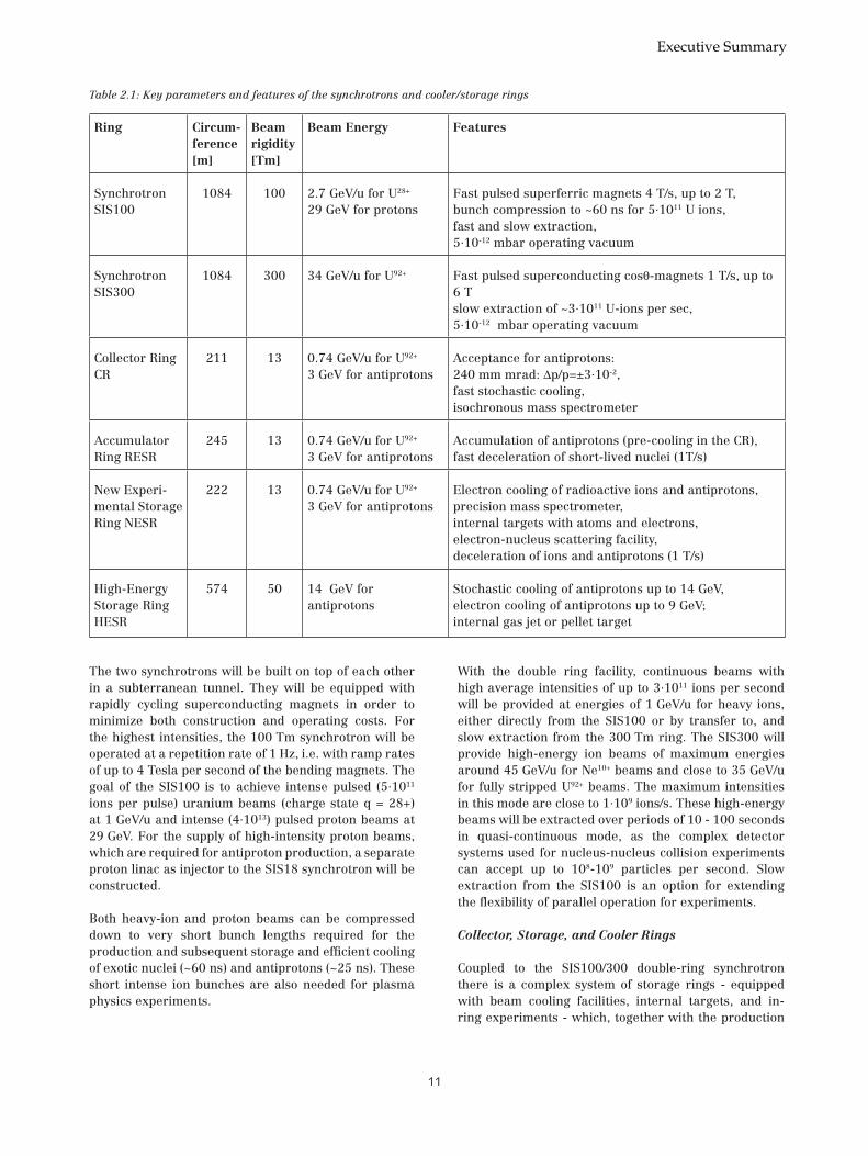
Table 2.1: Key parameters and features of the synchrotrons and cooler/storage rings
Ring Circum-ference [m]
Beam rigidity [Tm]
Beam Energy Features
Synchrotron SIS100
1084 100 2.7 GeV/u for U28+
29 GeV for protonsFast pulsed superferric magnets 4 T/s, up to 2 T, bunch compression to ~60 ns for 5·1011 U ions, fast and slow extraction, 5·10-12 mbar operating vacuum
Synchrotron SIS300
1084 300 34 GeV/u for U92+ Fast pulsed superconducting cosθ-magnets 1 T/s, up to 6 T slow extraction of ~3·1011 U-ions per sec, 5·10-12 mbar operating vacuum
Collector Ring CR
211 13 0.74 GeV/u for U92+ 3 GeV for antiprotons
Acceptance for antiprotons: 240 mm mrad: ∆p/p=±3·10-2, fast stochastic cooling, isochronous mass spectrometer
Accumulator Ring RESR
245 13 0.74 GeV/u for U92+ 3 GeV for antiprotons
Accumulation of antiprotons (pre-cooling in the CR), fast deceleration of short-lived nuclei (1T/s)
New Experi-mental Storage Ring NESR
222 13 0.74 GeV/u for U92+ 3 GeV for antiprotons
Electron cooling of radioactive ions and antiprotons, precision mass spectrometer, internal targets with atoms and electrons, electron-nucleus scattering facility, deceleration of ions and antiprotons (1 T/s)
High-Energy Storage Ring HESR
574 50 14 GeV for antiprotons
Stochastic cooling of antiprotons up to 14 GeV, electron cooling of antiprotons up to 9 GeV; internal gas jet or pellet target
Executive Summary

��
targets and separators for antiproton beams, secondary and radioactive ion beams, provides an unprecedented variety of particle beams at FAIR.
The additional storage rings are:
The Collector Ring (CR) for stochastic cooling of radioactive and antiproton beams. Moreover, the CR allows mass measurements of short-lived nuclei using the time-flight method in the isochronous operation mode.
The Accumulator Ring (RESR) for accumulation of antiproton beams after stochastic pre-cooling in the CR and also for fast deceleration of radioactive secondary beams with a ramp rate of up to 1 T/s.
The New Experimental Storage Ring (NESR) for experiments with exotic ions and with antiproton beams. The NESR is equipped with stochastic and electron cooling. Further instrumentation includes precision mass spectrometry using the Schottky frequency spectroscopy method, internal target experiments with atoms and electrons, an electron-nucleus scattering facility, and collinear laser spectroscopy. Moreover, the NESR serves to cool and to decelerate stable and radioactive ions as well as antiprotons for low energy experiments and trap experiments at the FLAIR facility.
The High-Energy Storage Ring (HESR) for antiproton beams at energies of 3 GeV up to a maximum energy of 14.5 GeV. The ring is equipped with electron cooling up to an energy of 8 GeV (5 MeV electron energy maximum) and for stochastic cooling up to 14.5 GeV. The experimental equipment includes an internal pellet target and the large in-ring detector PANDA as well as
an option for experiments with polarized antiproton beams.
Tables 2.1-2.3 provide more detailed information on the key parameters of the proposed double synchrotron, on the primary beam parameters that will be achieved with the SIS100/300 double synchrotron, and on the specific ways the various research programs will use the FAIR accelerator facility.
2.4 Modifications to the Conceptual Design Report
Compared to the preliminary facility layout presented in the original Conceptual Design Report, the present layout contains a number of modifications and improvements:
• Increase in the magnetic rigidity of the second synchroton ring from 200 to 300 Tm (SIS200 SIS300) in order to increase the maximum energy to about 35 GeV/u for U92+ beams.
• Addition of a storage ring (RESR) to achieve the desired accumulation and cooling performance.
• Change of HESR injection and operating mode (as well as of its location). Injection of antipro- tons will take place from the CR/RESR facility at particle energy of 3 GeV. The HESR will be equipped with accelerator structures for acceleration up to 14.5 GeV. Moreover, a proton beam line for com- missioning and, as a future option, for injection of polarized proton beams into the HESR from the SIS18 has been added.
• Modifications to the injection and extraction positions of the synchrotrons.
Research Field Energy Peak Intensity Average Intensity Pulse Structure
Radioactive Ion Beams
0.4 to 1.5 GeV/ufor all elements up to uranium
~5·1011 per pulsefor storage ring experiments
~3·1011 per secondhigh duty cycle for fixed target experiments
~60 nsfor injection into the storage ring
Antiprotons 29 GeV protons 4·1013 per cycle -- ~25 ns
Dense Nuclear Matter 45 GeV/u for A/q=0.5 up to 34 for A/q=2.7
-- 2·109 per second --
Plasma Physics
0.4 to 1 GeV/u ions ~1012 per pulse -- 50 - 100 ns (fixed target)
Atomic Physics
0.1 to 10 GeV/u ions -- --
Table 2.2: Primary beam parameters from the SIS100/300 facility for the different research fields
FAIR Baseline Technical Report

��
• Re-design of the high-energy beam transport systems and experimental stations to reduce costs
2.5 Parallel Operation and Synergy
An important consideration in the design of the facility was a high degree of a truly parallel operation of different research programs. Simple beam splitting and switching to different target locations is of course generally possible at any accelerator. But this does not increase the integrated luminosity. Truly parallel operation aims for providing maximum integrated beam time and luminosity for each of the different programs running in parallel. The proposed scheme of synchrotrons and storage rings, with their intrinsic cycle times for beam acceleration, accumulation, storage and cooling, respectively, has the
potential to optimize such a parallel and highly synergetic operation. This implies that the facility operates for the different programs like a dedicated facility. Figure 2.2 illustrates how parallel operation performs with a cooled and accumulated antiproton beam, in parallel to a fixed target experiment with radioactive beams or relativistic heavy-ion beams slowly extracted from the second synchrotron ring SIS300 and an additional beam for plasma physics.
2.6 Technological Challenges
The beam characteristics aimed for at the FAIR facility are challenging. In order to achieve them, new technological approaches are to be pursued. The most important aspects to be addressed are:
Ring Radioactive Ion Beams
Antiprotons Dense Nuclear Matter
Plasma Physics Atomic Physics
Synchrotron SIS100
~5·1011 U ions per pulse, pulse compression to ~60 ns,
~4·1013 protons per pulse, pulse compression to ~25 ns,
up to 2·1011 ions per pulse, for injection to SIS300
~5·1011 U ions per pulse, pulse compression to ~60 ns,
109 ions per second, high duty cycle
Synchrotron SIS300
~3·1011 U ions per second, high duty cycle
- 1·109 ions per second, high duty cycle, up to 34 GeV/u U
- Laser spectroscopy
Collector Ring CR fast stochastic cooling, isochronous mass spectrometer for short-lived nuclei
fast stochastic cooling, high acceptance
- - -
Accumulator Ring RESR
fast (1T/s) deceleration of short-lived nuclei
accumulation of antiprotons
- - -
New Experimental Storage Ring NESR
fast (1T/s) deceleration of short-lived nuclei, electron cooling, precision mass spectrometer, electron-nucleus scattering
fast (1T/s) deceleration of antiprotons
- - electron cooling, internal target,deceleration and extraction to FLAIR,SPARC
High-Energy Storage Ring HESR
- 0.8-14 GeV antiprotons
- - -
Table 2.3: Usage of the accelerator and storage rings by the different research fields
Executive Summary

�4
Control of the dynamic vacuum pressure. Beam-loss induced desorption of heavy molecules can cause the rapid increase of the residual gas pressure. In order to maintain the ultra-high vacuum conditions needed for operation with partly stripped heavy ions, a novel collimation concept has been developed which is presently being tested at the SIS18.
Operation with high brightness, high current beams. The synchrotrons will operate close to the space charge limits with tolerable beam losses in the order of a few percent. The control of collective instabilities and the reduction of the ring impedances is a subject of the present R&D phase.
High rf voltage gradients. Fast acceleration and compression of the intense heavy-ion beams require compact rf systems. Complex rf manipulations with minimum phase space dilution and the reduction of the total beam loading in the rf systems are important R&D issues.
Fast cycling superconducting magnets. For SIS100, super-conducting magnets with 2 T maximum field
and with 4 T/s ramping rate are required. SIS300 will be equipped with 6 T (1 T/s) dipole magnets. The optimization of the magnet field quality for low loss, high current operation with beams filling large parts of the acceptance is therefore of great importance and an issue of intense R&D.
Cooled secondary beams. Fast electron and stochastic cooling at medium and at high energies will be essential for experiments with exotic ions and with antiprotons. In order to achieve the required luminosities in the antiproton storage ring HESR, magnetized electron cooling at high energies (5 MeV) will be necessary, which represents a step beyond the only existing high energy electron cooler at Fermilab.
In the last five years, substantial R&D work has been dedicated to the aforementioned technological aspects. Considerable progress has been achieved and the principal feasibility of the proposed technical approaches been demonstrated. Prototyping of certain components has started. For details see Volume 2.
SIS300SIS 18
ProtonLinac
PlasmaPhysics
HADES* + CBM
AtomicPhysics
HESR
Super-FRS
RadioactiveIon Beams
Pbartarget
AntiprotonPhysics
FLAIR
CR
RESR
p
pbar
plasma physics
atomic physics
CBM
RIB storage ring
RIB ext. target NESR
UnilacSIS100
Figure 2.2: Schematic of parallel operation at the new facility. Up to four different scientific programs are served in parallel: A proton beam (orange), accelerated in SIS100, produces antiprotons (orange dashed) in the antiproton target-station, which are then collected, accumulated and cooled in the CR/RESR storage-ring combination, and transferred either to the HESR or to the NESR for experiments. In parallel, i.e. during the fraction of the SIS100 super-cycle not needed for the protons, a primary ion beam is accelerated in SIS100 and slowly extracted to the Super-FRS to produce radioactive secondary beams for fixed target experiments (violet-dashed) or for stor-age in the CR and NESR instead of antiprotons (blue-dashed). In addition, every 10-100 seconds a high-energy heavy-ion beam (red) is accelerated in SIS100/300 and slowly extracted for nuclear collision experiments. Moreover, intense compressed beam pulses (green) are provided every few minutes for plasma physics experiments that require very low repetition rates. Alternatively, atomic physics experiments (light blue) may be served by SIS100 in the pauses of the antiproton production.
FAIR Baseline Technical Report

��
3. Experimental Programs and Collaborations
3.1 Overview
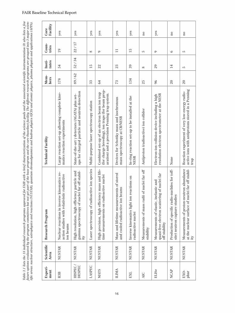
In general terms, the research goals and scientific objectives of the science at FAIR can be grouped into 3 major areas: i) a deeper understanding of the structure and properties of matter; this includes a reduction of the structure of matter to the basic building blocks and fundamental laws, forces and symmetries; and an understanding how complexity arises from these fundamental constituents, a complexity which does not come from a simple linear superposition but involves non-linear processes, correlations and coherences; ii) contributions to our knowledge about the evolution of the Universe; the hierarchical structure of matter, from the microscopic to the macroscopic, is directly related to the sequence of steps in the evolution and generation of the visible world; iii) use of ion beams in technology and applied research
These general research goals can be grouped into the following specific fields of research at FAIR:
• Nuclear structure and nuclear astrophysics with beams of stable, but in particular also of short-lived (radioactive) nuclei far from stability;
• Hadron structure, the theory of the strong interaction quantum chromo-dynamics (QCD), and the QCD vacuum, primarily with beams of antiprotons;
• The nuclear matter phase diagram and the quark- gluon plasma with beams of high-energy heavy ions;
• Physics of very dense plasmas with highly compressed heavy-ion beam bunches in unique combination with a petawatt laser currently under construction;
• Atomic physics, quantum electro-dynamics (QED) and ultra-high electro-magnetic fields with beams of highly-charged heavy ions and antimatter;
• Technical developments and applied research with ion beams for materials science and biology.
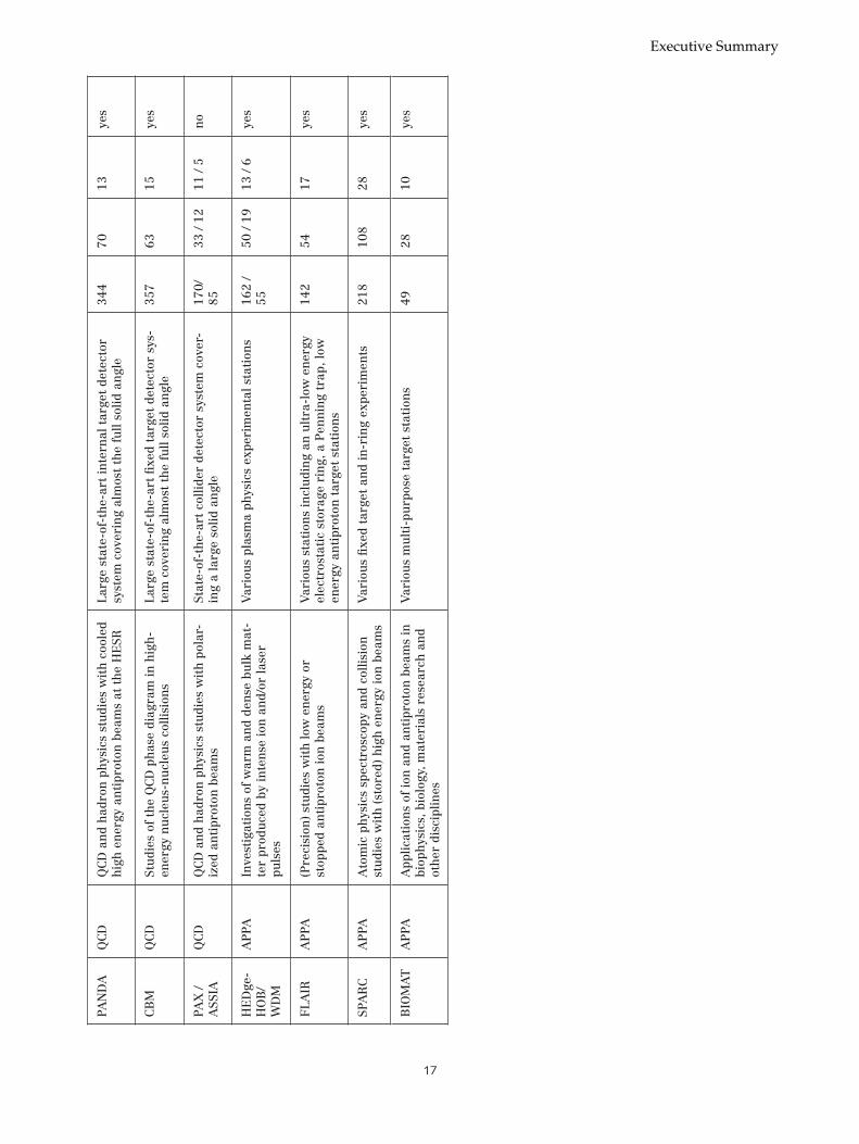
The respective experiment proposals and collaborations are listed in Table 3.1. The table also indicates the major experimental apparatus involved in the respective research programs.
Each individual experiment has been thoroughly reviewed by an international Program Advisory Committee (PAC). The experiments that have been included in the core facility were selected on basis of scientific merit, discovery potential and technical feasibility. Possible extension to the baseline research program have also been included.
Executive Summary
��
Exp
eri-
men
tSc
ien
tifi
c A
rea
Res
earc
h P
rogr
amT
ech
nic
al F
acil
ity
Mem
-b
ers
Inst
i-tu
tes
Cou
n-
trie
sC
ore
F
acil
ity
R3B
NU
STA
RN
ucl
ear
reac
tion
s in
inve
rse
kin
emat
ics
re-
acti
on s
tudi
es w
ith
rel
ativ
isti
c ra
dioa
ctiv
e io
n b
eam
s
Larg
e re
acti
on s
et-u
p al
low
ing
com
plet
e ki
ne-
mat
ics
reac
tion
exp
erim
ents
178
5419
yes
HIS
PE
C /
DE
SPE
CN
UST
AR
Hig
h r
esol
uti
on, h
igh
effi
cien
cy p
arti
cle
and
gam
ma
spec
tros
copy
of
nu
clei
far
off
sta
bil-
ity
Stat
e-of
-th
e-ar
t γ
dete
ctor
s (A
GA
TA)
plu
s se
t-u
ps f
or c
har
ged
part
icle
an
d n
eutr
on d
etec
tion
89 /
6252
/ 34
22 /
17ye
s
LASP
EC
NU
STA
RLa
ser
spec
tros
copy
of
radi
oact
ive
ion
spe
cies
Mu
lti-
purp
ose
lase
r sp
ectr
osco
py s
tati
on33
158
yes
MA
TS
NU
STA
RH
igh
pre
cisi
on, h
igh
effi
cien
cy m
ass
and
life-
tim
e m
easu
rem
ents
on
rad
ioac
tive
nu
clei
Com
bin
ed s
et-u
p of
an
ele
ctro
n b
eam
ion
tra
p (f
or c
har
ge b
reed
ing)
, ion
tra
ps (
for
beam
pre
p-ar
atio
n)
and
a pr
ecis
ion
Pen
nin
g tr
ap s
yste
m.
6422
9ye
s
ILIM
AN
UST
AR
Mas
s an
d lif
etim
e m
easu
rem
ents
of
stor
ed
and
cool
ed r
adio
acti
ve io
n b
eam
sD
evic
es f
or S
chot
tky
mas
s an
d is
och
ron
ous
mas
s sp
ectr
osco
py a
t C
R/N
ESR
7323
11ye
s
EX
LN
UST
AR
Inve
rse
kin
emat
ics
ligh
t io
n r
eact
ion
s on
ra
dioa
ctiv
e n
ucl
eiIn
-rin
g re
acti
on s
et-u
p to
be
inst
alle
d at
th
e N
ESR
134
3915
yes
AIC
NU
STA
RM
easu
rem
ents
of
mas
s ra
dii o
f n
ucl
ei f
ar o
ff
stab
ility
An
tipr
oton
(ra
dioa
ctiv
e) io
n c
ollid
er25
85
no
ELI
SeN
UST
AR
Mea
sure
men
ts o
f el
asti
c, in
elas
tic
and
quas
i-fr
ee e
lect
ron
sca
tter
ing
of n
ucl
ei f
ar
off
stab
ility
Ele
ctro
n-i
on c
ollis
ion
dev
ice
incl
udi
ng
a h
igh
re
solu
tion
ele
ctro
n s
pect
rom
eter
at
the
NE
SR96
299
yes
NC
AP
NU
STA
RP
rodu
ctio
n o
f sp
ecifi
c ra
dio-
nu
clid
es f
or (
off-
site
) n
eutr
on c
aptu
re s
tudi
esN
one
2014
6n
o
EX
O-
pbar
NU
STA
RM
easu
rem
ents
of
prot
on-n
eutr
on a
bun
dan
ce
at t
he
nu
clea
r su
rfac
e of
nu
clei
far
off
sta
bil-
ity
Rea
ctio
n e
xper
imen
t of
ver
y lo
w-e
ner
gy r
adio
-ac
tive
ion
s w
ith
an
tipr
oton
s st
ored
in a
Pen
nin
g tr
ap
205
5n
o
Tabl
e 3.
1 li
sts
the
18 i
nd
ivid
ua
l re
sea
rch
prog
ram
s a
ppro
ved
for
FA
IR w
ith
a b
rief
cha
ract
eriz
ati
on o
f th
e sc
ien
ce g
oals
an
d t
he a
ssoc
iate
d s
cien
tifi
c in
stru
men
tati
on (
It a
lso
list
s a
few
fu
ture
opt
ion
s ev
alu
ate
d b
y th
e pr
ogra
m c
omm
itte
es b
ut
not
yet
pa
rt o
f th
e ba
se p
rogr
am
an
d t
he c
ore
(ba
seli
ne)
fa
cili
ty. T
he d
iffe
ren
t re
sea
rch
prog
ram
s a
re g
rou
ped
into
3 m
ajo
r sc
ien
-ti
fic
are
as:
nu
clea
r st
ruct
ure
, ast
roph
ysic
s a
nd
rea
ctio
ns
(NU
STA
R),
qu
an
tum
chr
omod
yna
mic
s a
nd
ha
dro
n p
hysi
cs (
QC
D)
an
d a
tom
ic p
hysi
cs, p
lasm
a p
hysi
cs a
nd
app
lica
tion
s (A
PPA
).
FAIR Baseline Technical Report
��
PAN
DA
QC
DQ
CD
an
d h
adro
n p
hys
ics
stu
dies
wit
h c
oole
d h
igh
en
ergy
an
tipr
oton
bea
ms
at t
he
HE
SRLa
rge
stat
e-of
-th
e-ar
t in
tern
al t
arge
t de
tect
or
syst
em c
over
ing
alm
ost
the
full
solid
an
gle
344
7013
yes
CB
MQ
CD
Stu
dies
of
the
QC
D p
has
e di
agra
m in
hig
h-
ener
gy n
ucl
eus-
nu
cleu
s co
llisi
ons
Larg
e st
ate-
of-t
he-
art
fixe
d ta
rget
det
ecto
r sy
s-te
m c
over
ing
alm
ost
the
full
solid
an
gle
357
6315
yes
PAX
/ A
SSIA
QC
DQ
CD
an
d h
adro
n p
hys
ics
stu
dies
wit
h p
olar
-iz
ed a
nti
prot
on b
eam
sSt
ate-
of-t
he-
art
colli
der
dete
ctor
sys
tem
cov
er-
ing
a la
rge
solid
an
gle
170/
85
33 /
1211
/ 5
no
HE
Dge
-H
OB
/W
DM
AP
PAIn
vest
igat
ion
s of
war
m a
nd
den
se b
ulk
mat
-te
r pr
odu
ced
by in
ten
se io
n a
nd/
or la
ser
puls
es
Var
iou
s pl
asm
a ph
ysic
s ex
peri
men
tal s
tati
ons
162
/ 55
50 /
1913
/ 6
yes
FLA
IRA
PPA
(Pre
cisi
on)
stu
dies
wit
h lo
w e
ner
gy o
r st
oppe
d an
tipr
oton
ion
bea
ms
Var
iou
s st
atio
ns
incl
udi
ng
an u
ltra
-low
en
ergy
el
ectr
osta
tic
stor
age
rin
g, a
Pen
nin
g tr
ap, l
ow
ener
gy a
nti
prot
on t
arge
t st
atio
ns
142
5417
yes
SPA
RC
AP
PAA
tom
ic p
hys
ics
spec
tros
copy
an
d co
llisi
on
stu
dies
wit
h (
stor
ed)
hig
h e
ner
gy io
n b
eam
sV
ario
us
fixe
d ta
rget
an
d in
-rin
g ex
peri
men
ts21
810
828
yes
BIO
MA
TA
PPA
App
licat
ion
s of
ion
an
d an
tipr
oton
bea
ms
in
biop
hys
ics,
bio
logy
, mat
eria
ls r
esea
rch
an
d ot
her
dis
cipl
ines
Var
iou
s m
ult
i-pu
rpos
e ta
rget
sta
tion
s49
2810
yes
Executive Summary

��
FAIR will provide intense secondary beams of unstable isotopes across the entire nuclide chart. Beam intensities exceed those available at existing rare-isotope-beam facilities by several orders of magnitude and beam energies are variable up to more than 1 GeV/u. A superconducting in-flight separator (Super-FRS) serves external stations and coupled storage-cooler rings including an electron-ion collider. The novel instruments and experimental opportunities have attracted a large community of nuclear physicists addressing a broad research spectrum covering nuclear structure physics, nuclear astrophysics, and studies of fundamental interactions and symmetries. Proposals for experiments at the FAIR Rare-Isotope-Beam facility were presented by international collaborations, organized in the broader umbrella collaboration NUSTAR (Nuclear Structure, Astrophysics, and Reactions) with more than 700 members in total. Altogether 9 experimental programs are presently planned at the three branches of the Super-FRS. In the following, a brief overview will be given on the planned programs and experiments; for a detailed description we refer to Volume 4 of this Baseline Technical Report.
3.2.1 Physics Case
The atomic nucleus has proven to be an exceedingly interesting many-body system that has come up with surprises over and over again. The building blocks are protons and neutrons, both spin 1/2 particles, which are themselves complex many-body structures composed of quarks and gluons. The Quantum Chromo Dynamical (QCD) degrees of freedom are, however, not excited in low energy explorations of the nucleus. The underlying QCD-structure rather manifests itself in a complex nucleon-nucleon force with spin- and isospin-dependent terms. A strong short-range repulsion is balanced by long-range attractive interactions including also spin-orbit and tensor forces. A strongly correlated self-bound quantum system, the nucleus is thus formed that exhibits a wide spectrum of phenomena.
Exciting new aspects of nuclear structure are coming from the study of exotic short lived nuclei by means of secondary beams of radioactive nuclei. Much of what we know about nuclei comes from nuclear reactions. In the past, these were limited to stable nuclei, available as target materials, in bombardements with beams of (other) stable nuclei, in particular light nuclei. Having short-lived nuclei available as energetic beams, now allows to extend such studies in an inverse laboratory kinematics to unstable radioactive nuclei away from stability. Exotic nuclei are characterized by an extreme excess of protons or neutrons and are thus located far away from
the valley of stability. New structural phenomena are to be expected, such as very different proton and neutron density distributions with proton/neutron skins or halos, or such as new excitation modes that are not observed in stable nuclei. A study of such effects is of paramount interest for a complete understanding of the isospin and density dependence of the effective in-medium forces and of pairing and clusterization phenomena. With increasing isospin, the Fermi surface of the excess nucleons moves towards the continuum threshold, the sectors of bound and unbound states are not separated anymore to the extent as in stable nuclei. Correlations resulting from substantially differing Fermi edges and the appearance of weekly bound single-particle levels lead, in consequence, to new magic numbers.
Evidently, only by synergy of theory and experiment, the new challenges in nuclear structure physics can successfully be approached. The bulk of nuclear structure models employs effective interactions whose parameters have been adjusted to known nuclear data, basically to that for stable nuclei. The study of nuclei far away from stability at FAIR will provide additional data on the nuclear many-body system under extreme conditions which should be understood in a consistent and microscopic framework. The ultimate goal is to find a unified description of nuclei and their properties based on the principles of low-energy QCD and the fundamental interactions between nucleons.
Reactions between nuclei play a decisive role in many astrophysical processes in the Universe. Nuclear struc-ture effects and the dynamics of nuclear reactions are directly reflected in the various evolutionary stages of stars, in the light curves of stellar explosions, and in the elemental abundance distributions in the Universe. Current key questions in nuclear astrophysics are: the origin of the chemical elements, the physics of stellar explosions, the different nuclear and mixing processes in stars, the understanding of compact objects like white dwarfs and neutron stars and the thermonuclear explo-sions on their surfaces, which are observed as novae or x-ray bursts. Unstable nuclei, far away from stability, are involved and their properties determine the fate of the relevant astrophysical processes.
At the FAIR facility it will be possible for the first time to experimentally determine the properties of many of these unstable nuclei. FAIR will, in particular, deliver de-cisive contributions to the understanding of the origin of the heavy elements, of core-collapse (type II) and ther-monuclear (type Ia) supernovae, of the physics of com-pact objects and the explosions on their surfaces (novae,
3.2 Nuclear Structure, Astrophysics and Reactions with Rare-Isotope-Beams - the NUSTAR Collaborations
FAIR Baseline Technical Report

��
x-ray bursts). Simultaneously, the next generation of astronomical observatories, as well as refined analysis of star dust from meteorites, will produce a wide range of data of unprecedented quality about the elemental abundance distribution and stellar explosions. Supple-mented by advances in nuclear theory and theoretical astrophysics these novel nuclear and astronomical data will result in a unified picture of the processes in the Universe, which are responsible for our existence.
3.2.2 The Rare-Isotope-Beam Facility at FAIR
Studies with Rare Isotope Beams (RIB) form one of the major research programs at FAIR. The radioactive beam facility at FAIR offers world-wide unique experimental opportunities for this area of research. The secondary beams of unstable nuclei are produced by fragmentation of a primary heavy-ion beam or by fission of an 238U beam at energies up to 1.5 GeV/u, followed by in-flight separation in a partially superconducting magnetic separator (Super-FRS).
The facility at FAIR surpasses in many respects the capabilities of that of existing RIB facilities and competes with corresponding projects in Japan and USA in particular by innovative experimental concepts through instrumentation not available elsewhere.
The FAIR synchrotrons, operated in a high-intensity modus (primary beam intensities of several 1011 ions per second), together with the extraordinary phase-space acceptance of the in-flight fragment separator (Super-FRS) yields secondary beam intensities with several orders of magnitude higher than available presently. Since the production process is chemically not selective and since the transport time is negligible, isotopes even of shortest lifetimes can be provided and be studied. Secondary beams are delivered with high purity in a wide range of beam energies and with variable (pulsed or quasi-dc) time structure and are eventually delivered to the target stations or are injected into storage rings.
The Super-FRS has to efficiently separate in-flight rare isotopes produced via projectile fragmentation of all primary beams up to 238U and via fission of 238U beams. The latter reaction is a prolific source of very neutron-rich nuclei of medium mass. However, due to the relatively large amount of kinetic energy released in the fission reaction, the products populate a large phase space and thus demands for an extraordinary acceptance. Compared to the in-flight fragment separator (FRS) existing presently at GSI, more than one order of magnitude is gained in transmission of fission products due the increased momentum and angular acceptance.
Figure 3.1: Schematic view of the rare-isotope-beam facility at FAIR with the superconducting in-flight separator (Super-FRS) and its three experimental branches: the high-energy reaction area, the low-energy area, and the storage ring complex (CR-RESR-NESR) with the intersecting electron collider (eA).
Executive Summary
�0
Besides fragment intensities, selectivity and sensitiv-ity are the crucial parameters that strongly influence the success of an experiment with very rare nuclei. A prerequisite for a clean isotopic separation is that the fragments have to be fully ionized to avoid cross con-tamination from different ionic charge states. Multiple separation stages are necessary to efficiently reduce the background from such contaminants. Based on the expe-rience of successful spatial isotopic separation with the existing FRS at GSI, the Super-FRS also uses the Bρ-∆E-Bρ method, where a two-fold magnetic rigidity analysis is applied in front of and behind a specially shaped ener-gy degrader. The high primary beam intensities expect-ed from the SIS100/300 synchrotrons require additional measures to achieve the aimed for separation quality. A straight forward consequence is that the Super-FRS consists of a two-stage magnetic system, the pre- and the main-separator, both equipped with a degrader.
The demand for fully stripped fragments requires operation in the high-energy domain. On the other hand, the thicknesses of production target and degraders have to be optimized to prevent substantial losses due to secondary nuclear reactions. The above physics criteria as well as optimization of the performance and cost considerations have led to the choice of 20 Tm as maximum magnetic rigidity of the Super-FRS.
3.2.3 Experiments at the Rare-Isotope-Beam Facility
The secondary rare isotope beams produced and separated at the Super-FRS can be delivered to three experimental branches allowing for a diverse and highly flexible program at particle energies from rest up to 1 GeV/u. These branches are:
The high-energy branch
At the high-energy branch, an experimental area has been foreseen for high-energy reaction studies in inverse kinematics employing an apparatus of highest efficiency and full solid-angle coverage. For this, the R3B collaboration has designed an experimental set-up capable of fully benefiting from the Super-FRS beams with the characteristics inherent to the in-flight production method. Located at the focal plane of the high-energy branch of the Super-FRS, R3B is a versatile fixed-target detector with high efficiency, acceptance, and resolution for kinematically complete measurements of reactions with high-energy radioactive beams, even at very low beam intensities down to one ion per second. Such complete kinematics measurements were in the past very successful in discoveries of new structural phenomena, e.g. of halo structures, new collective modes, or of new shell closures. Mainly for intensity reasons, the experiments were restricted to light-mass
nuclei, at FAIR they can be extended to heavy nuclei far off stability.
The research program planned by the R3B collaboration covers a wide variety of scattering experiments, i.e., such as heavy-ion induced electromagnetic excitation, knockout and breakup reactions, or light-ion (in)elastic and quasi-free scattering in inverse kinematics. Capture rates derived from Coulomb dissociation and Gamow-Teller strength distributions derived from charge-exchange reactions are of prime astrophysics interest.
The low-energy branch
At the Low-Energy Branch, it will be possible to study properties and phenomena of exotic nuclei employing mono-energetic low-energy beams from the Super-FRS (energies ranging from about 100 MeV/u down to a few MeV/u, stopped beams, and re-accelerated beams of a few tens of keV). An ‘energy-buncher’ allows for a par-tial compensation of the beam energy spread induced by the passive slowing-down process. Four collaborations (HISPEC/DESPEC, LASPEC, MATS, NCAP) proposed ex-periments at the low-energy branch.
HISPEC/DESPEC deals with a versatile, high-resolution, high-efficiency spectroscopy set-up to address questions in nuclear structure, reactions and astrophysics using radioactive beams with energies of 3-150 MeV/u (HISPEC) or stopped and implanted beam species (DESPEC). In-beam γ−ray and particle spectroscopy after (multiple) Coulomb excitation and other reactions in the low to intermediate energy regime are performed using the AGATA Ge array and charged particle detectors. Decay spectroscopy (β-decay, isomer decay, exotic decays) after stopping and implantation of the fragment beams in a silicon detector stack surrounded by modular γ-ray and neutron arrays or by a total-absorption spectrometer is the subject of DESPEC.
The LASPEC collaboration proposes a multi-purpose laser spectroscopy station for the study of stopped, cooled and bunched radioactive species. It will permit, by a variety of optical techniques, the model-independent determination of isotopic and isomeric nuclear spins, magnetic dipole moments, electric quadrupole moments and changes in mean square charge radii. A variety of fluorescence, resonance ionization and polarization based spectroscopic techniques will be applied.
The MATS collaboration proposes measurements of high accuracy and high sensitivity suitable to very short-lived radionuclides. Two techniques are applied, high-precision mass measurements and in-trap conversion electron and alpha spectroscopy. The experimental setup of MATS combines an electron beam ion trap for charge
FAIR Baseline Technical Report

��
breeding, ion traps for beam preparation, and a high precision Penning trap system for mass measurements and decay studies.
The NCAP collaboration is interested in the production of specific radio-nuclids for off-site neutron-capture studies providing input needed in stellar models.
The ring branch.
Presently, GSI is the only research center worldwide hosting a facility (FRS-ESR) which allows accumulating radioactive beams in a storage-cooler ring. This invoked new experimental techniques, e.g. for mass measure-ments or in observing exotic decay modes. The stor-age ring concept will be further developed at FAIR by a multi-storage-ring system (CR-RESR-NESR) linked to the Super-FRS.
The coupled storage rings offer a high collection effi-ciency for secondary beams, and electron cooling com-bined with stochastic pre-cooling results in high-quality (with regard to emittance and momentum spread) beams within cooling periods of below one second. High lumi-nosities can be achieved in consequence and allows for the first time for in-ring reaction experiments. Hadronic scattering experiments at low momentum transfer with high sensitivity to transition multipolarity and spin-isospin selectivity are of prime interest. Moreover an electron-ion collider ring will be coupled to the ion stor-age ring NESR allowing studies of unstable nuclei by a purely electromagnetic probe. Storage of antiprotons in the collider ring and studying antiproton-ion collisions is a further option being considered.
Four collaborations (ILIMA, EXL, ELISe and AIC) pro-posed experiments at the ring branch. All proposals take advantage of the unique capabilities offered by the multi-storage/collider ring system at FAIR. In particular they benefit from the much improved beam quality due to stochastic and electron cooling.
The ILIMA experimental program concerns mass and lifetime measurements of stored bare and highly charged nuclides as well as the access to pure isomeric beams. Such measurements are relevant both, for nuclear structure and astrophysics. The ILIMA concept
builds on the very successful methods of ‘Schottky Mass Spectrometry’ and ‘Isochronous Mass Spectrometry’ , both pioneered at the ESR storage-cooler ring at GSI. The sensitivity of the two methods can substantially be improved at the CR and NESR rings, respectively, at FAIR.
The objective of the EXL collaboration is to capitalize on light-ion induced direct reactions at intermediate energies in inverse kinematics at an internal target in the NESR storage ring. Elastic and inelastic scattering, charge-exchange reactions, quasi-free scattering and transfer reactions can be studied with a universal detector setup. Due to their spin-isospin selectivity, light-ion induced direct reactions at intermediate to high energies are an indispensable tool in nuclear structure studies as evident from investigations of stable nuclei in the past. Such experiments enable for example precise measurements of mass distributions, of single-particle spectral functions, or of the electric and mag-netic multipole response. Because of the kinematical conditions of inverse kinematics in case of beams of unstable nuclei, low-momentum transfer measurements, as envisaged, turn out to be an exclusive domain of storage ring experiments.
The ELISe proposal aims at elastic, inelastic, and quasi-free electron scattering by using intersecting ion and electron storage rings and an electron spectrometer with high resolution and large solid angle coverage complementing the EXL detector measuring the strong interaction radius. Both experiments together can discover neutron or proton halo in nuclei. The experiment will be installed at the New Experimental Storage Ring (NESR) where cooled secondary beams of radioactive ions collide with an intense electron beam circulating in a small electron storage ring.
The Antiproton-Ion Collider (AIC) collaboration proposed a collider experiment to measure rms-radii for protons and neutrons in stable and short lived nuclei by means of antiproton absorption at medium energies. The experiment makes use of the electron-ion collider (see above) with appropriate modifications of the electron ring in order to store, cool and collide antiprotons of 30 MeV energy with 740 MeV/u ions in the NESR.
Executive Summary

��
The PANDA collaboration proposes to study fundamental questions of hadron and nuclear physics in interactions of antiprotons with nucleons and nuclei, using the universal PANDA detector. Gluonic excitations and the physics of strange and charm quarks will be accessible with unprecedented accuracy thereby allowing high-precision tests of the strong interaction. The proposed PANDA detector is a state-of-the-art internal target detector at the HESR at FAIR covering almost the full solid angle.
3.3.1 Physics Motivation
The strong force governs the microscopic structure of matter. It dominates the interaction between the nucleons, i.e. the protons and neutrons within the atomic nucleus, and it is the key force that determines the interaction between the quarks within the nucleon and within other hadrons (strongly interacting particles). Achieving a fully quantitative understanding of matter at this level is one of the challenging and fascinating areas of modern physics. During the last two decades hadronic physics has moved from phenomenological to a more fundamental understanding. The theory of Quantum Chromodynamics (QCD) is regarded as the basic theory of the strong interaction. While being elegant and deceptively simple, the theory generates a most remarkable richness and complexity of phenomena. The possible forms of matter range from the spectrum of strongly interacting hadrons and nuclear species to compact stars of extreme density and to the quark-gluon plasma, a state of matter in the early universe and, possibly, in the interior of very heavy stars.
The fundamental building blocks of QCD are the quarks which interact with each other by exchanging particles, the gluons. QCD is simple and well understood at short-distance scales, much shorter than the size of a nucleon (< 10-15 m). In this regime, the basic quark-gluon interaction is sufficiently weak. Here, perturbation theory can be applied, a calculation technique of high predictive power yielding accurate results when the coupling strength is small. In fact, many processes at high energies can quantitatively be described by perturbative QCD within this approximation.
The perturbative approach fails when the distance among quarks becomes comparable to the size of the nucleon, the characteristic dimension of our microscopic world. Under these conditions, the force among the quarks becomes so strong that they cannot be further separated, in contrast to the electromagnetic and gravitational forces which fall off with increasing distance. This unusual behavior is related to the self-interaction of gluons: gluons do not only interact with quarks but also
with each other, leading to the formation of gluonic flux tubes connecting the quarks. As a consequence, quarks have never been observed as free particles and are confined within hadrons, complex particles made of 3 quarks (baryons) or a quark-antiquark pair (mesons). Baryons and mesons are the relevant degrees of freedom in our environment. An important consequence of the gluon self-interaction and — if found — a strong proof of our understanding of hadronic matter is the predicted existence of hadronic systems consisting only of gluons (glueballs) or bound systems of quark-antiquark pairs and gluons (hybrids).
In the evolution of the universe, some microseconds after the big bang, a coalescence of quarks to hadrons occurred associated with the generation of mass. The elementary light quarks, the up and down quarks, that make up the nucleon have very small masses amounting to only a few percent of the total mass of the nucleon. Most of the nucleon mass, and of the visible universe stems from the QCD interaction. The generation of mass is associated with the confinement of quarks and the spontaneous breaking of chiral symmetry, one of the fundamental symmetries of QCD in the limit of massless quarks.
The phenomena of the confinement of quarks, the existence of glueballs and hybrids, and the origin of the mass of strongly interacting, composite systems related to confinement and the breaking of chiral symmetry are long-standing puzzles and represent the intellectual challenge in our attempt to understand the nature of the strong interaction and of hadronic matter. GSI has a distinguished history of having made important contributions to the physics of strong interactions, in particular nuclear physics. The proposed PANDA experiment will enable the new FAIR facility to play a significant role in strong interaction physics, providing a link between nuclear physics and hadron physics.
3.3.2 Research Program
The proposal demonstrates that antiproton beams of unprecedented intensity and quality in the energy range of 1 GeV to 15 GeV, as provided by the new FAIR facility together with PANDA, will be an excellent tool to address fundamental questions. Antiproton beams in this energy regime, stored in the High-Energy Storage Ring (HESR) for in-ring experiments, will provide access to the heavier strange and charm quarks and to copious production of gluons. As illustrated in Figure 3.2, the physics program offers a broad range of investigations that extend from the study of Quantum Chromodynamics to the test of fundamental symmetries.
3.3 Hadron Physics with Antiproton Beams - the PANDA Collaboration
FAIR Baseline Technical Report

��
The key components of the antiproton program are summarized as follows:
The determination of the interaction potential through precision spectroscopy has been a successful tool at all levels of the structural hierarchy of matter, as for example in atoms and molecules. The charm quark is sufficiently heavy to lend itself to non-relativistic perturbative treatment far more reliably than the light up, down, and strange quarks. Thus, an optimal testing ground for a quantitative understanding of confinement is provided by charmonium spectroscopy, i.e. the spectroscopy of mesons built of charmed quark-antiquark pairs (cc). Recently, completely unexpected and surprising results in form of the discovery of new states in the charmonium mass region show that this field is far from being understood experimentally and theoretically.
The proposed program, using resonant antiproton-proton annihilation, is a quantitative and qualitative extension of successful experiments performed at the antiproton accumulator at FNAL, USA. However, those experiments which ended in the year 2000 were limited in scope by lower antiproton energies (< 9 GeV), lower luminosities (≤ 2.5·1031 cm-2s-1) and a detector only capable of detecting electromagnetic reaction products. At FAIR, advanced antiproton cooling techniques will enable high energy resolution and a more versatile detector setup will be employed allowing for the first time a measurement of both electromagnetic and hadronic decay modes with high precision. The goal is to achieve comprehensive precision spectroscopy of the
charmonium system for a detailed study, particularly of the confinement part of the QCD potential. This in turn will help to understand the key aspects of gluon dynamics which are being investigated and quantitatively predicted in the framework of Lattice QCD.
Previous experiments at LEAR/CERN have demonstrated that particles with gluonic degrees of freedom are produced copiously in proton-antiproton annihilation in the light quark sector. A central part of the antiproton program presented in this proposal is the first search for gluonic excitations, glueball and hybrids, in the charmonium mass range where they are expected to be less mixed with the multitude of normal mesons. The unambiguous determination of the gluonic modes would establish an important missing link in the confinement problem of hadrons.
GSI has an active ongoing program on the modification of the properties (masses, widths, etc) of light mesons (pions and kaons) by the nuclear medium and the relation to the partial restoration of chiral symmetry. The proposed experimental program at the HESR will address the open problem of interactions and in-medium modifications of hadrons with charm quarks in nuclei. Additionally, the program will provide the first insight into the gluonic charmonium-nucleon and charmonium-nucleus interaction. A quantitative knowledge of charmonium-nucleon cross sections is considered to be of crucial importance in the identification of the formation of the quark-gluon plasma in ultra-relativistic heavy-ion collisions.
0 2 4 6 8 12 1510
p Momentum [GeV/c]
Mass [GeV/c2]
Two bodythresholds
Molecules
GluonicExcitations
q Mesonsq
1 2 3 4 5 61 2 3 4 5 6
Hybrids
Hybrids+Recoil
Glueballs
Glueballs+Recoil
DD
DsDs
qqqq ccqqqqqq ccqq
nng,ssg ccgnng,ssg ccg
ggg,gg
light qq cclight qq cc
nng,ssg ccgnng,ssg ccg
ggg
ΛΛ
ΣΣ
ΞΞ ΩΩ
Λ Λ
Σ Σ
Ξ Ξ
c
c
c c
c
c
Ω Ωc c
π ρ ω, , ,f ,K,K2
*J/ , ,ψ η χc cJ
Figure 3.2: Mass range of hadrons accessible at the HESR with antiproton beams. The figure indicates the antiproton momenta required for charmonium spectroscopy, the search for charmed hybrids and glueballs, the production of D meson pairs and the production of S baryon pairs for hypernuclear studies. The energy range covered by the former Low Energy Antiproton Ring (LEAR) at CERN is indi-cated by the arrow.
Executive Summary

�4
A new and largely unexplored dimension in the chart of nuclides is introduced by replacing an up or down quark by a strange quark in a nucleon bound in a nucleus, leading to the formation of a hypernucleus. Here, the strangeness quantum number is introduced into the nucleus. Antiproton beams at the proposed facility will allow efficient production of hypernuclei with more than one strange hadron. The program opens new perspectives for nuclear structure studies and is a novel complement to the proposal to study the structure of nuclei with radioactive beams. The nucleon with the strange quark (hyperon) is not restricted in the population of nuclear states as neutrons and protons are. These exotic nuclei offer a variety of new and exciting perspectives in nuclear spectroscopy and for studying the forces among hyperons and nucleons.
One of the most important symmetries of physics is CP symmetry (charge conjugation C times spatial parity P). CP symmetry implies that the laws of physics apply to a system after the combined action of exchanging particles by their antiparticles and by reflection of the system in a spatial mirror. However, if CP symmetry was perfectly obeyed, none of the matter in the universe, neither stars nor human beings, would exist since matter and antimatter would have annihilated each other. The observed dominance of matter in the universe may be attributed to CP violation, an effect directly observed in the decay of neutral kaons and, very recently, in B mesons. CP violation can be studied in the charm meson sector and in hyperon decays, with the HESR storage ring running at full luminosity. An observation of significant CP violation would indicate physics beyond the Standard Model.
Two of the research areas with antiprotons, the in-medium properties of charmed hadrons and the structure of atomic nuclei with one or more strange hadrons, are examples of the close intellectual connection between the physics with antiprotons and two other major thrusts of the FAIR proposal, relativistic nucleus-nucleus collisions and nuclear structure physics with radioactive beams. They contribute in a synergetic way to the broader goal of a deeper understanding of the structure of hadronic matter in all its forms. Finally, the close connection between the various components of the present proposal is evident in the pursuit of symmetry tests and symmetry breaking effects, which are the key for our understanding of how the world is built from the fundamental building blocks.
3.3.3 Instrumentation and Detector
The technical capabilities and the uniqueness of the proposed facility are of great importance in the realization of the research objectives. Therefore the accelerator, and in particular the beam properties of the
HESR, have to be matched to the PANDA detector. Beam cooling techniques are mandatory to deliver the beams of unprecedented quality and precision to the internal target facility with an advanced detector system.
The PANDA detector design incorporates the most recent technologies in order to reach the required performance criteria with regard to mass, momentum and energy resolution, hit resolution, particle identification, and solid angle coverage. The combination of the high-quality antiproton beam and the detector system provides a powerful and unique facility, unparalleled worldwide, to carry out the research discussed in the main section of the report.
One important goal is to achieve almost full hermiticity. The detector has to be able to track particles down to momenta of 100-200 MeV/c and up to a maximum of 8 GeV/c. A vertex detector is required since many channels include charm mesons. A key component is electromagnetic calorimetry with excellent resolution. Furthermore, particle identification of kaons, protons, and muons is mandatory.
The general layout of PANDA is based on two magnetic spectrometers and is shown in Figure 3.3. The target spectrometer surrounds the interaction region and has a superconducting solenoid as momentum analyzer. A forward opening of 5-10° (depending on the respective axis) allows high momentum tracks to enter the forward spectrometer with a large gap dipole magnet.
3.3.4 Interaction Region
Various targets are considered for the different physics programs within PANDA. Most of the measurements require a proton target which can be realized in two alternative ways:
• A pellet target device produces a stream of small pellets of frozen hydrogen falling through and interacting with the antiproton beam. This type of target is able to achieve average densities in the order of up to 1016 cm-2s-1. That would match the desired luminosity of 2·1032 cm-2s-1 at a gas load compatible with a low cross section for pumping around the interaction region. Furthermore, by having several hundred interactions within one pellet, it is possible to track its flight path and determine the individual interaction points precisely.
• The second option is a cluster jet target which sends an ultra-dense hydrogen jet through the beam. It provides a homogeneous stream of gas which is easy to handle from the accelerator point of view.
FAIR Baseline Technical Report

��
Currently, the R&D work is focussing on improving the densities such that the design luminosity of PANDA can be reached. However, the achieved densities are still well below 1016 cm2.
As the requirements on a target for different types of experiments are manifold, it is not clear, whether one target will be able to fulfill all of them. Thus currently both targets are foreseen on equal footing and would fit into the detector. A cluster jet target or a pellet target can also be used for reactions with nuclei. However, in this case higher luminosities and a better definition of the interaction point are provided by using wire or strip targets. The use of an internal gas storage cell, e.g. a target of polarized 3He, is proposed and has to be studied.
3.3.5 Target Spectrometer
The defining element of the target spectrometer is the superconducting solenoidal magnet. It has a length of 2.5 m, a diameter of 1.9 m and an axial field of 2 T. It has to accommodate a gap for pipes of the target device. The target spectrometer is made up of the following components:
• The interaction point is surrounded by a Micro Vertex Detector (MVD) which has five barrel shaped layers plus five disk-shaped detectors in forward direction. The three innermost layers are composed of pixel detectors to achieve best resolution and to be able to easily detect decay vertices displaced from the interaction point. The outer layers are composed
of microstrip detectors which are easier to handle. The baseline technology chosen for the pixel detectors are hybrid active pixel sensors as used by several LHC experiments. The electronics still has to be modified to accommodate continuous readout. As alternatives to silicon pixels, GaAs based detectors are considered as well as much thinner monolithic pixel sensors where the problem of radiation hardness would have to be solved.
• The MVD is surrounded by a cylindrical tracker. Two options are currently discussed, a straw tube tracker (STT) consisting of a set of double layers of self-supporting straws and a time projection chamber (TPC) with continuous readout. The TPC is the technically more challenging option since it requires an ungated charge collection based on a Gas Electron Multiplier (GEM) readout. However it has the benefit of less material and offers in addition particle identification via dE/dx. On the other hand, the STT is seen as a safe fall-back solution which should still fulfil the basic tracking requirements. In the forward direction circular or octagonal mini drift chambers are used to track particles with higher momenta before they enter the forward spectrometer.
• The next detector is a Cherenkov counter based on the so-called DIRC principle (Detector for Internally Reflected Cherenkov Light) as used in BaBar at SLAC. It consists of quartz rods in which Cherenkov light is internally reflected to an array of photon detectors in the backwards direction. The readout can be
RICH EMC
754-1 1 2 3
EMC
EMC
hadron calorimeter
MDC
MDCMUO
MUO
10o
22o
0
STT or TPC
MVDbeam
6
dipoleDIRC
EMC
MDCor
STT
TOF stop
8 109
TOF stop
TOF stop
coil
DIRC
140o
solenoid
target spectrometer forward spectrometer
Figure 3.3: Setup of the PANDA detector.
Executive Summary

��
either done by imaging a 2D pattern of reflections with a large number of PMTs or APDs or by measuring just one coordinate and the time of light propagation inside the quartz very precisely. In forward direction a disk-shaped Cherenkov counter with quartz radiator and detectors for internally reflected light similar as for the barrel DIRC is planned. Its readout should be located between the solenoid coil and the return yoke to allow the calorimeter end cap to be as close as possible.
• An electromagnetic calorimeter is placed outside the DIRC. It consists of a barrel part with 11360 crystals, a forward end cap with 6864 crystals and a backward end cap with 816 crystals. As detector material PbWO4 is foreseen, since it is fast and has a reasonable resolution. As alternative BGO with still higher light yield albeit slower signals is considered.
• Finally, outside the superconducting magnet and its iron return yoke, drift tubes track muons exiting the spectrometer.
The necessity of a time-of-flight detector in the target spectrometer is still under discussion. Although the flight path is short, low momentum particles could still be identified.
3.3.6 Forward Spectrometer
The heart of the forward spectrometer is a dipole magnet with a large opening and a field integral of 2 Tm. This will provide the required momentum resolution for forward tracks with momenta up to 8 GeV/c.
One problem of the dipole magnet is the deflection of the beam. If included in the beamline design it can be countered by a magnet chicane. Otherwise the beam could be shielded from the magnetic field, introducing some material in the acceptance. A completely different option would be the usage of a toroidal magnet in the forward spectrometer. Although providing an azimuthal symmetry nicely matching to the target spectrometer it reduces the acceptance at small angles and requires the instrumentation of a larger area with trackers and calorimeters. The detector systems in the forward spectrometer are summarized in the following:
• Tracking is provided by mini drift chambers. Before the magnet, they have the same octagonal shape as in the end cap of the target spectrometer. After the magnet, a rectangular shape matches is more suitable for the spread of tracks. The use of straw tube trackers inside the dipole field is considered for better momentum resolution.
• The option of a third Cherenkov counter, based on gas or aerogel is still under investigation. In addition, a time-of-flight detector is considered for charged particle identification.
• An electromagnetic calorimeter based on lead/ scintillator sampling and WLS fibre readout (Shashlyk type) is foreseen in the forward spectrometer. It should have 276 channels to cover the acceptance and will reach a resolution in the range of 3-5%/√E [GeV].
• After the electromagnetic calorimeter, the use of the MIRAC detector from WA80 at CERN is under investigation as a hadron calorimeter after refurbishing its readout.
• The last piece of equipment is a muon detector based on drift tubes.
3.3.7 Data Acquisition and Trigger
The selected readout and trigger concept foresees continuous digitization of all detector channels. Special trigger hardware is not foreseen. The readout electronics has to be fully pipelined and has to perform autonomously the detection of valid hits as well as intelligent data reduction by clusterization, signal shape analysis, and time reconstruction to transfer only the physically relevant minimum of information. All data are marked by a synchronous time-stamp by which event building can be performed at a later stage.
The data are fed into a configurable network. Attached computer nodes with the required bandwidth digest the full rate of certain sub-detectors used for the first selection level. Other detectors transfer data only for time slices selected on some level. Parallel selections are possible and several levels will bring the data rate down to the required 100-200 MB/s to mass storage. The clear advantage of this scheme is its flexibility: Any conceivable physics signature of an interesting process measurable by the PANDA detector could be converted into a sequence of selection algorithms. Typical signatures are the decays of J/y to leptons, decay vertices of charm or strange hadrons, identified kaons or electromagnetic showers, etc. The level of complexity is only limited by the required processing power and can be scaled up by attaching more nodes.
The trigger system and the universality of the detector make PANDA a unique tool in hadron physics, ready for future challenges.
FAIR Baseline Technical Report

��
The Compressed Baryonic Matter (CBM) Collaboration, comprising about 350 scientists, aims for the investigation of strongly interacting matter at very high baryon densities including the question of deconfinement and chiral phase transitions. The envisaged research is complementary to the programs conducted at the Relativistic Heavy Ion Collider (RHIC) at BNL and at the future Large Hadron Collider (LHC) at CERN which focuses on the study of the phase diagram at high temperatures. CBM is designed to operate at interaction rates of up to 107 reactions per second with multiplicities of up to ~1000 charged particles per nucleus-nucleus collision event. Such parameters require unprecedented detector performance in terms of read-out speed and radiation hardness.
3.4.1 Exploring the QCD Phase Diagram with Heavy-ion Collisions
In the laboratory, hot and dense nuclear matter can be generated in a wide range of temperatures and densities by colliding atomic nuclei at high energies. In the collision zone, the matter is heated and compressed for a very short period of time. If the energy pumped into this fireball is sufficiently large the quark-gluon substructure of nucleons comes into play. At first, nucleons are excited to short-lived states (baryonic resonances) which decay by the emission of mesons. At higher temperatures, also baryon-antibaryon pairs are created. This mixture of
baryons, antibaryons and mesons, all strongly interacting particles, is generally called hadronic matter, or baryonic matter if baryons prevail. At even higher temperatures or densities the hadrons melt, and the constituents, the quarks and gluons, may move freely forming a new phase, the Quark-Gluon-Plasma. At very high densities but very low temperatures, correlated quark-quark pairs are predicted to form a color superconductor. These phases predicted for strongly interacting matter are illustrated in Fig. 3.4.
Heavy-ion experiments at RHIC and the future LHC aim at the study of strongly interacting matter at extremely high temperatures and low net baryon densities, i.e. at very small values of the baryon chemical potential. In this region of the phase diagram the transition is expected to be a smooth crossover from hadronic to partonic matter. Recent Lattice QCD calculations found strong indications for the existence of a critical endpoint at relatively large values of the baryon chemical potential. Beyond this critical endpoint, for larger values of the baryon chemical potential (and for lower temperatures), one expects a first order phase transition from hadronic to partonic matter. This is the regime of high baryon densities which will be investigated in detail by the CBM experiment. Nucleus-nucleus collisions at FAIR energies cover a large area of the QCD phase diagram ranging from dense nuclear and hadronic matter to the first order phase transition, potentially including its critical
Figure 3.4: Schematic illustration of the phase diagram of strongly interacting matter.
3.4 The Phase Diagram of Strongly Interacting Matter - the CBM Collaboration
Executive Summary

��
endpoint. The discovery of the critical endpoint would be a breakthrough in high-energy heavy-ion research, as this observation would constitute the first direct signature for the deconfinement phase transition.
3.4.2 The Scientific Goals of the CBM Experiment
The high-intensity heavy-ion beams of the future FAIR accelerators, together with the planned Compressed Baryonic Matter (CBM) experiment, offer excellent opportunities to produce and to investigate baryonic matter at highest densities in the laboratory. The research program comprises the study of the structure and the equation-of-state of baryonic matter at densities comparable to the ones in the inner core of neutron stars. This includes the search for the phase boundary between hadronic and partonic matter, the critical endpoint, and the search for signatures for the onset of chiral symmetry restoration at high net-baryon densities.
The experimental and theoretical challenge is to study probes which address the physics topics mentioned above. In high-energy nucleus-nucleus collisions the evolution of the fireball - from the early hot and dense stage to its disintegration into hadrons - takes only a few 10-23 s. The experimental observables are the yields and phase-space distributions of newly created particles, and their correlations and fluctuations. Different particle species probe different phases of the transient fireball depending on their mass, energy, production and interaction cross sections and decay channels.
Particles containing heavy quarks like charm are created in the early phase of the collision, in particular at FAIR energies which are close to the threshold for the production of charm-anticharm pairs. Therefore, the yield and the phase space distributions of charmed particles are expected to be particularly sensitive to the conditions inside the evolving early fireball. Most of the charm quarks are carried away in D-mesons which contain one charm and one light quark. Theory predicts that the properties of D-mesons are modified in the dense medium, and, hence, offer the possibility to study the effect of chiral symmetry restoration at highest densities. Some of the created charm-anticharm pairs form charmonium which disintegrates much easier in quark-gluon matter than in hadronic matter, thus probing the structure of the fireball. No charmed particles have been measured in the FAIR energy range.
A direct view into the hot and dense fireball is provided by short-lived vector mesons decaying into electron-positron or muon pairs. These leptons do not interact strongly and thus act as penetrating probes. From the invariant mass distribution of the dilepton pairs one can extract the in-medium spectral functions of the vector mesons which contain information on the effect of chiral
symmetry restoration. Up to now, dilepton mass spectra have not been measured in the FAIR energy range.
Heavy particles containing strange quarks like φ-mesons (strange - antistrange pair), Ξ hyperons (two strange quarks and one light quark) or Ω hyperons (three strange quarks) are produced in the high temperature and high density phase but may decouple soon from the fireball due to their low interaction cross sections with hadronic matter. Their yields, momentum and angular distributions may be affected by the conditions inside the reaction zone.
In the final dilute stage of the collision the participant hadrons cease to interact and the abundance of the various particle species is frozen. The pion and kaon yields reflect the amount of entropy and strangeness created in the collision. A detailed experimental study of the correlations and fluctuations of the most abundant particles provides information on the bulk properties of the fireball. The collective motion of the emitted particles can be related to the compressibility of the hot and dense matter as described by its equation-of-state. In atomic matter, in the vicinity of the critical endpoint of a first order phase transition, a strong enhancement of density fluctuations occurs, causing critical opalescence. In the case of heavy-ion collisions, similar critical phenomena are expected, thus an enhancement of fluctuations of particle yields or of their mean transverse momentum at a given beam energy has been proposed as a signature for the critical endpoint. These dynamical, i.e. non-statistical fluctuations have to be measured event-by-event which requires a detector with a large acceptance and excellent particle identification capability.
The observation of thermal radiation from the collision zone would give direct experimental access to the fireball temperature. However, these photons are notoriously difficult to extract from the measured photon spectrum which is dominated by decay photons. Recently, the analysis of two-photon correlations opened the possibility to disentangle photons from the dense and hot fireball and decay photons.
The CBM experimental program includes the investigation of nucleus-nucleus collisions at beam energies from about 10 GeV/u to 35 GeV/u for lead projectiles and up to 45 GeV/u for symmetric projectile nuclei (Z/A=0.5). The aim is to provide a comprehensive and precise data set based on the measurements of the observables mentioned above for a variety of projectile and target masses, beam energies, and impact parameters. Important for the interpretation of results of the heavy-ion collision experiments are comparisons to data obtained in proton-nucleus and proton-proton collisions. The FAIR accelerators deliver proton beams up to an energy of 90 GeV which permits investigations
FAIR Baseline Technical Report

��
of elementary processes like charm production in an energy range where no data exist. Nuclear reactions in the energy range from 2 to 10 GeV/u will be studied with an upgraded HADES spectrometer, which is currently being operated at the GSI SIS-18 accelerator.
3.4.3 The CBM Detector Concept
The CBM collaboration proposes to build a universal detection system in order to fully exploit the physics potential of nucleus-nucleus collisions at FAIR. The proposed detector will be capable of simultaneously measuring both, hadrons and leptons, over a large geometrical acceptance. A key feature of the apparatus will be its capability to perform high-rate measurements which are needed for the identification of rare probes, such as the D-meson and charmonium, in a large background of charged particles. The experimental setup will be operated at interaction rates of up to 107
reactions per second with multiplicities of up to ~1000 charged particles per central gold-gold collision. Such conditions require unprecedented detector performances in terms of read-out speed and radiation hardness.
A schematic view of the proposed CBM detector concept is shown in Fig. 3.5 together with the HADES spectrometer. In the present design, the STS consists of three planar layers of silicon-pixel detectors downstream from the target followed by four layers of micro-strip detectors which provide excellent tracking capabilities and secondary vertex reconstruction even in the anticipated high track density environment. The STS is located inside the large gap of the dipole magnet for momentum determination with a precision of better than 1%. The task of the RICH detector will be to identify electrons and to provide suppression of pions in the momentum range of electrons from low-mass vector-meson decays. The TRD detector will provide charged particle tracking and
Figure 3.5: Schematic view of the Compressed Baryonic Matter (CBM) experiment planned at FAIR. The setup consists of a high resolu-tion Silicon Tracking System (STS), a Ring Imaging Cherenkov detector (RICH), three stations of Transition Radiation Detectors (TRD), a time-of-flight (TOF) system made of Resistive Plate Chambers (RPC) and an Electromagnetic Calorimeter (ECAL). The HADES spectro-meter which will be used for experiments between 2 and 10 GeV/u beam energy, is located upstream the CMB target.
Executive Summary
�0
the identification of high energy electrons and positrons. The technical task is to develop highly granular gaseous detectors operating at rates up to 100 kHz/cm2. At the same time, a pion rejection factor of several hundred at an electron detection efficiency of 90% should be achieved. Hadron identification will be performed using a TOF wall consisting of a RPC array. The key issues here are the high rate capability, low resistivity material, long-term stability and the realization of large arrays with overall excellent timing performance. The required time precision should be well below 100 picoseconds and the expected particle flux for the innermost part of the detector is up to 25 kHz/cm2. The ECAL will be used for the identification of electrons and photons.
A particularly challenging aspect of CBM is the requirement for a high-speed data acquisition (DAQ) architecture and the appropriate trigger concept. The DAQ system has to provide the necessary bandwidth to process sufficient events for an efficient reconstruction of rare probes and should also permit a high degree of flexibility in order to be adjustable to the different physics needs of the experiment.
The CBM detector components are currently the object of intensive research and development activities carried out by different groups within the collaboration and achievable technical solutions have been proposed for all components.
3.4.4 Feasibility and Performance Studies
Detailed simulations concentrate on the optimization of the detector configuration in order to assure that the key observables are accessible with sufficient precision. The studies are based on efficient track- and vertex recon-struction algorithms which take into account a realistic response of the Silicon detectors including possible event pile-up. One of the benchmark observables are the D-mesons which will be identified via their hadronic decay
into one or two pions and a kaon. This measurement poses a major challenge to the Silicon tracker and an online event selection: the decay vertex of the D-meson - which is displaced from the main vertex of the collision by several 10 µm - has to de determined with an accura-cy of about 50 µm in order to suppress the overwhelming combinatorial background caused by pions and kaons directly emitted from the fireball. The simulations show that an event suppression factor of about 1000 can be achieved when using a thin and highly granulated ver-tex pixel detector. This factor is sufficient for effectively triggering on D-meson candidates even in gold-on-gold collisions at reaction rates up to 10 MHz.
Another key observable are short-lived vector-mesons which decay into lepton pairs with a branching ratio of 10-4-10-5. The major challenge, both for the measurement and for the data analysis, is to suppress the physical background of electron-positron pairs from Dalitz decays and gamma conversion. According to simulations based on an optimized Silicon tracker configuration one expects a signal-to-combinatorial background ratio of about 0.5 for ω- and φ-mesons in central gold-on-gold collisions at an energy of 25 GeV/u. This analysis requires a pion suppression factor of 104 which can be achieved by the combined performance of RICH and TRD.
The measurement of fluctuations and correlations requires a large detector acceptance with full azimuthal coverage, and excellent particle identification capabilities for a wide range of beam energies. Simulations demonstrate that the CBM setup permits to measure event-by-event dynamical fluctuations of the kaon-to-pion ratio down to a level of 2%.
The CBM Collaboration - which currently consists of about 350 scientists from more than 40 institutes and 15 countries - will prepare Technical Design Reports for the different detector components until 2011, and will start with the experimental program in 2015.
FAIR Baseline Technical Report

��
FAIR will deliver very intense, bunched and highly focused heavy-ion beams of all ion species up to uranium. Such beams will deposit hundreds of kJ/g specific energy in solid matter that will induce exotic states of High-Energy-Density (HED) in the material. A strong plasma physics community, comprising about 120 scientists and organized within the “High Energy Density generated Heavy-iOn Beams-Collaboration (HEDgeHOB)”, aims for utilizing the powerful ion beams from FAIR to carry out novel research into matter under extreme conditions of temperature and pressure; similar conditions are believed to prevail in the interiors of stars, brown dwarfs and giant planets. A second group comprising about 60 scientists organised in the ‚Warm Dense Matter‘ (WDM) collaboration will focus on the optical properties of matter under these exotic conditions. This research will largely benefit from the availability of the kilojoule/petawatt laser facility PHELIX, which is presently being set up at GSI.
3.5.1 Physics Motivation
In the environment that we are used to, matter occurs predominantly in the solid, liquid or gaseous phase. However, in the universe at large, the situation is quite different. The small fraction of visible matter exists predominantly either as hot dense plasma in the interior of stars or in stellar atmospheres, as medium- or low-temperature dense plasma in the interior of large planets, or as hot plasma of very low density in interstellar space. In particular the regime of dense plasmas is so far only scarcely explored, since it is difficult to approach experimentally. This regime corresponds to states of matter at specific energies of larger than 105 J/cm3 or equivalent pressures of 1 Mbar and above, which are classified as High-Energy-Density (HED) matter.
Intense heavy-ion beams provide an efficient tool to create large samples of HED matter (with volumes of the order of a few mm3 or even cm3 and lifetimes of the order of several ten’s of nanoseconds) by isochoric and uniform heating of solid matter. The uniform physical conditions and comparatively long life times facilitate application of a broad spectrum of the diagnostic tools for studying these HED states of matter. Already today GSI accelerators deliver the most intense heavy ion beam for plasma physics experiments. The beam parameters of the new FAIR facility outnumber the current status in many respects: The specific energy deposition, for example, will increase from 1 kJ/g, which is a typical value for current experiments, to about 600 J/g, and the specific power deposition from 1 gigawatt/g to 12 terawatts/g.
3.5.2 Research Program
The research program envisaged at FAIR will focus the equation of state of metals in so far unexplored regions of the phase diagram, the properties of compressed matter at medium temperatures, and related to these major goals, studies of the interaction of intense ion and laser radiation with heated and compressed matter, radiation hydrodynamics, magneto-hydrodynamics, etc. Two complementary experimental concepts are proposed by the HEDgeHOB collaboration (Fig. 3.6):
HIHEX (Heavy Ion Heating and Expansion): In the HIHEX experiment, a cylindrical or plane target is heated fast compared to the hydrodynamic expansion time. By such quasi-isochoric heating, high entropy states as well as high energy density states are generated. After heating, the sample isentropically expands and passes through the regions of interest in the phase diagram. The variability of the beam focus at the target allows for cylindrical and plane geometry. This allows in many cases to reduce the numerical description to a one dimensional problem.
LAPLAS (Laboratory Planetary Sciences): LAPLAS scenario makes use of cryogenic targets like solid hydrogen and other noble gases, confined by an outer cylinder of heavier material, such as lead or gold. The outside cylinder is heated by a beam with an annular focal spot. While the outer material is heated and subsequently expands, the inner cryogenic material is not heated, stays cold and is compressed by the expansion process of the outer cylinder. This ensures compression of the investigated material at low entropy.
Figure 3.6: Experimental concepts and beam-target configura-tions of the proposed HEDgeHOB experiments. HIHEX (Heavy Ion Heating and Expansion) experiments: to measure equation of state (EOS) data by quasi-isochoric heating and isentropic expansion. Shown is a cylindrical and planar target geome-try. The beam comes from behind and heats the target mate-rial (small orange cylinder or thin orange foil, respectively). LAPLAS (Laboratory Planetary Sciences): low-entropy cylindri-cal compression of matter.
3.5 High Energy Density Bulk Matter Generated with Intense Heavy Ion and Laser Beams - the HEDgeHOB and the WDM Collaborations
Executive Summary

��
The WDM-experiments intend to explore the radiative properties and related atomic physics issues of heavy ion beam generated dense strongly coupled plasmas. In order to confine targets even at longer pulse lengths while keeping them transparent for diagnostic purposes, WDM has proposed the dynamic confinement scheme where the expansion of the inner material can be counteracted by the expansion of the very thin outer transparent cylinder. The aim of this experimental scheme is to achieve isochoric heating of low-Z materials even for long pulses.
When the pulse lengths is sufficiently short, the radiative properties of Warm Dense Matter samples can be explored even without the confining outer shell.
X-ray Thomson scattering driven by the PHELIX laser is proposed to independently characterise the WDM samples and to benchmark the spectroscopically recorded radiation emission and related atomic physics in dense environments.
LAPLAS and HIHEX will use diagnostic tools such as Thomson scattering, x-ray backlighting and proton radiography to characterize the states which have been achieved. WDM will essentially employ spectrally resolved x-ray scattering diagnostics where the Petawatt High Energy Laser PHELIX will play a key role.
3.5.3 Instrumentation at FAIR
In order to exploit the accelerator facilities in the most optimal way, a dedicated experimental area has been specially designed for the Plasma Physics experiments at FAIR (Fig. 3.7). Two separate beam transport lines are coming from the SIS-100 synchrotron to the Plasma Physics cave. The ion-optical characteristics of these beam lines are optimized for different experiments. The left beam line is designed for the HIHEX experiment and allows for extremely strong final beam focusing and non-linear beam shaping. This is needed for efficient heating of the samples in order to achieve high entropy states in matter. The beam-heated material can then expand isentropically reaching different interesting physical states that are to be investigated in the HIHEX experiment.
The second beam line is designed for the LAPLAS and WDM experiments. LAPLAS in addition need a hollow beam with a ring-shaped focal spot whereas WDM employs the much more simple usual Gaussian beam profile. Such a beam is generated by a high-frequency beam rotator (wobbler) which forces the beam to make about 10 full circles at the target within the beam pulse duration of 50 ns that is sufficient to achieve the necessary level of the irradiation symmetry and homogeneity. Using such a beam, the sample material
like solid hydrogen, deuterium or water ice that is enclosed in a heavy cylindrical tamper shell can be strongly compressed while preserving low temperature. By such fairly ideal low-entropy cylindrical compression, one can reach the high pressure states that are the subject of the LAPLAS experiment. This beam line is also equipped with an elaborate cryogenic target preparation and handling system needed for both LAPLAS and WDM experiments.
The high energy Petawatt PHELIX laser beam is requested for the HIHEX, LAPLAS target stations for diagnostics purposes. In addition, a 90º ion beam from the SIS-18 synchrotron allows for high-resolution ion and proton radiography in the HIHEX experiment.
The high energy Petawatt PHELIX laser beam is also requested for the WDM target station, however, no SIS-18 nor proton radiography are needed as they are not useful for the WDM research program.
Figure 3.7: Layout of the Plasma Physics experimental area at FAIR. The HIHEX (green) and LAPLAS/WDM (cyan) SIS-100 beam lines are coming from the top of the picture. The dia-gnostic SIS-18 beam line (red) and PHELIX laser beam line (blue) are shown as well.
FAIR Baseline Technical Report

��
FAIR promises the highest intensities for relativistic beams of stable and unstable heavy nuclei, combined with the strongest available electromagnetic fields, allowing extension of atomic spectroscopy and collision studies across virtually the full range of atomic matter. Moreover, the new facility will produce the highest flux of cooled antiprotons worldwide and will facilitate the creation of low-energy antiprotons at high intensities and brilliances to be used in a physics program including atomic collision studies and precision spectroscopy of antiprotonic atoms and of antihydrogen. Organized within the Stored Particle Atomic Physics Research Collaboration (SPARC) and the Facility for Low-energy Antiproton Ion Research Collaboration (FLAIR), a large community of around 350 scientists will exploit these new opportunities for a challenging program on atomic and fundamental physics research.
3.6.1 Atomic Physics with Highly Charged Ions
The atomic physics program planned by the SPARC Collaboration will focus on to two major research themes, fundamental interactions between electrons and heavy nuclei (in particular the interactions described by Quantum Electrodynamics, QED) and collision dynamics in strong electromagnetic fields. Moreover, atomic physics techniques will be used to determine properties of stable and unstable nuclei and to perform tests on predictions of fundamental theories besides QED.
The SPARC Collaboration plans essentially for the four classes of experimental studies:
Highly relativistic heavy ions will be employed for a wide range of collision studies involving photons, electrons and atoms, exploiting the large Doppler boost and the rapidly varying fields in those reactions. An understanding of these collision phenomena is required for all lines of research in atomic physics, including the interaction in solids (material research) or in living cells (radiobiology), and also for accelerator technology. The Doppler boost will also allow completely new experiments using laser excitation.
High-energy beams will be utilized for achieving high stages of ionization up to bare uranium nuclei. Experiments will focus on structure and collision studies for these ion species, a field being still largely unexplored but intimately connected to astrophysics. It also facilitates precision investigations of bound state QED in extremely strong electromagnetic fields, e.g. for the ground-state of high-Z ions.
Fundamental atomic physics studies and model-independent determination of nuclear quantities with stable as well as radioactive atoms in well-defined charge states will be performed, through the application of atomic physics methods. Important for this class of experiments will be the slowing-down, trapping and cooling of particles in the ion trap facility HITRAP, enabling high-accuracy experiments in the realm of atomic and nuclear physics (e.g. g-factor measurements in heavy hydrogen-like ions), or collision studies by use of highly charged ions at extremely low energy.
Low-energy beams of high Z few-electron ions will be employed for collisions characterized by very large Sommerfeld parameters q/v. In this domain of strong perturbations, the ionization mechanism is unclear. No perturbation theories are applicable and corresponding experiments will be best suited to test the predictive power of the most advanced ab initio theories.
3.6.2 Instrumentation for SPARC
The experimental areas at the new facility provide a range of novel instrumentation for atomic and applied research:
The high-energy area for atomic physics will be sup-plied by ion beams from both SIS18 and SIS300. SIS300 will provide an unprecedented combination of high in-tensities and acceleration of particles up toγ= 35. Ad-ditionally, laser installations will be available; in particu-lar, the high power PHELIX facility will allow the study of interactions of the most intense laser fields with heavy ions.
The NESR (compare Fig. 3.8) will be of particular relevance for the atomic physics program. Compared to all other heavy-ion storage rings either currently in operation or planned, the NESR will be the most flexible, providing the most intense beams available, including bare uranium. The intense beams of highly-charged radioactive ions make novel experiments possible at the interface of atomic and nuclear physics. Moreover, new instrumentation will be available, such as an internal gas jet, an ultra-cold electron target, and electron bunches provided by the electron collider for interactions with collinear high-intensity laser pulses. The unprecedented resolution provided by the electron target will facilitate measurement of suitable line shapes, providing the opportunity to measure resonance profiles due to di-electronic recombination to a level where QED effects manifest in the observed line-shapes,
3.6 Atomic and Fundamental Physics with Highly Charged Ions and Antiprotons - the SPARC and the FLAIR Collaborations
Executive Summary

�4
thereby providing a significant new test of dynamical QED. Products of interactions with the internal target can be detected by a suite of spectrometers including X-ray crystal spectrometers (3-120 keV energy range), low-temperature calorimeters, a Compton polarimeter, an electron spectrometer and an extended reaction microscope with many of the products being detected with almost 4πacceptance. This facilitates a large range of new, kinematically complete collision experiments, as well as new tests of high field QED through spectroscopy of the subsequent transitions.
Low-Energy Cave and FLAIR Building The interaction of the highly charged ions, in the energy range of 130 MeV/u to < 100 keV/u, with composite targets (molecules, clusters, nanostructures and solids) will be investigated, in the new Atomic Physics low-energy cave located in the FLAIR (Facility of Low-Energy Antiproton and Ion Re-search) building. This experimental area will be served by the NESR. In the building, different installations (e.g. the Low-Energy Storage Ring LSR, the Ultra-low energy Storage Ring USR, and HITRAP) are located. From the LSR the ions can be actively slowed down, even to rest using the trap facility HITRAP. The installations will be shared with the FLAIR collaboration (see below).
3.6.3 Physics with Low-Energy Antiprotons
The physics program envisaged with low-energy antiprotons covers a wide range of atomic, nuclear and particle physics
Precision spectroscopy of antiprotonic atoms and antihydrogen for tests of fundamental interactions and symmetries is the main topic of current low-energy antiproton physics at the Antiproton Decelerator (AD) of CERN. Antihydrogen, the simplest form of neutral antimatter consisting of an antiproton and a positron, promises one of the most precise tests of CPT symmetry through precision laser and microwave spectroscopy and comparison to hydrogen, the experimentally best studied atom. In order to reach the ultimate precision it is necessary to trap the antihydrogen atoms in a neutral-atom trap and to laser-cool them to submilli-Kelvin temperatures. These extremely difficult experimental techniques will need many more years of development and will dominate the antihydrogen physics program at FLAIR. With the availability of laser-cooled antihydrogen, for the first time experiments on the gravitational properties of antimatter will become possible.
Interaction of antimatter with matter: exploring sub-femtosecond correlated dynamics is another major program at FLAIR. Here, atomic collision processes like ionisation by ultra-low energy antiprotons will be investigated. Antiprotons are a unique probe for these processes since they do not undergo charge screening like protons. Experimental data are scarce so far due to the unavailability of high-quality antiproton beams at these energies, and theoretical predictions vary considerably. At energies below about 500 keV down to 1 keV the interaction time between an antiproton passing atoms or molecules (70 attoseconds to 1 femtosecond) is comparable to the revolution time of outer-shell electrons
injectionextraction(to FLAIR)
electron cooler
electrontarget
gas-jettarget
NESR
electron collider
Figure 3.8: The New Experimental Storage Ring NESR with its instrumentation for atomic physics experiments.
FAIR Baseline Technical Report

��
in atoms or molecules. Moreover, the antiprotons’s electric field is so strong that any perturbative theoretical approach must fail. Therefore, slow antiprotons provide an unsurpassed, precise and unique tool to study many-electron dynamics in the strongly correlated, non-linear, sub-femtosecond time regime, the most interesting and, at the same time, most challenging domain for theory. A novel electrostatic storage ring for low-energy antiprotons, improving the luminosity by several orders of magnitude, equipped with state-of-the art imaging momentum spectrometers to record, simultaneously ,the vector momenta of several emitted electrons and ions (“Reaction Microscopes”), will allow for the first time detailed experimental studies in this regime.
Nuclear and particle physics with antiprotons is currently impossible because of the availability of only fast extracted antiprotons, i.e. pulsed beam at the AD. Already at LEAR, measurements of X-rays from light and heavy nuclei have been used to investigate the nucleon-antinucleon interaction at threshold or the nuclear periphery. With the availability of unstable nuclei at FAIR, these techniques can be extended to investigate the structure of unstable nuclei with antiprotons. Other ideas include the production of strangeness -2 systems or the production of nuclear clusters containing two
Kaons. For the latter, densities of 5-6 times normal nuclear density have been predicted, thus, reaching in the phase diagram of hadronic matter conditions where phase transitions to kaon condensation or colour superconductivity at low temperature may be possible.
3.6.4 The FLAIR Facility
To make use of the world wide highest flux of antiprotons, as available at FAIR, a next generation low-energy antiproton facility, a proposal was made for dedicated experimental area, the Facility for Low-Energy Antiproton and Ion Research (FLAIR, see Fig 3.9); an important synergy comes from the fact that the components of FLAIR can be equally well used for highly charged ions. To extend the performance over the existing facility one has to produce cooled beams of antiprotons down to energies well below 100 keV so that they can be efficiently captured in charged-particle traps or stopped in low-density gas. Furthermore, also continuous beam will be available for nuclear and particle physics type experiments.
The key instruments to achieve this are two storage rings, the Low-energy Storage Ring (LSR, 30 MeV-300 keV) followed by the Ultra-low energy Storage Ring (USR, 300 keV-20 keV) and the HITRAP facility. The LSR is the essential instrument of FLAIR, taking beams of 30 MeV antiprotons decelerating them to 300 keV. The best choice for LSR is the already existing CRYRING at the Manne Siegbahn Laboratory in Stockholm, which could be adapted for the new requirements (high-energy injection, extraction, fast deceleration) by the MSL team.
The USR, a challenging new development of a decelerating electrostatic storage ring under way at the Max-Planck-Institute for Nuclear Research in Heidelberg, can be both used for previously mentioned in-ring experiments with a reaction microscope or to extract ultra-low energy antiprotons into experimental areas.
A second possibility to obtain such low-energy antiprotons will be the capture, cooling, and extraction from HITRAP. Several experimental areas are foreseen both behind the USR and behind HITRAP for experiments at lowest antiproton energies.
Three more areas are foreseen that partly receive also higher-energy beams directly from the NESR. In the low-energy cave, in addition to studies with highly charged ions, ultra-low energy antiprotons extracted from HITRAP will be available.
Higher energy antiproton beams ( E pbar < 300 MeV) will be available in two areas for nuclear and particle physics experiments and the study of medical applications.
beam from NESR
low-energy p
low-energy HCI
high-energy p
USR e+
LSR/CRYRING
HIT
RA
P
Laser Laboratory
Sources
Low-energy cave AP
4 - 100 MeV/u HCI 30 - 400 MeV p
< 4 MeV/u HCI 0.3 - 30 MeV p
< 0.1 MeV/u HCI 0.005 - 0.3 MeV p
Figure 3.9: Layout of FLAIR
Executive Summary

��
The FAIR synchrotrons SIS18 and SIS100 also offer new opportunities for radiobiology and materials research. To make use of the heavy-ion beams provided by SIS18 or SIS100, a dedicated multi-purpose irradiation facility (BIOMAT) will be installed at the high-energy beamline. It will be equipped with a magnetic scanner system, flexible irradiation set-ups and instrumentation for in-situ diagnostics of irradiated samples.
3.7.1 Science Case
The biophysics research program will focus on space radiation effects. Radiation represents a significant hazard in all space explorations, especially outside the protective shield of the Earth.s magnetic field. Solar and galactic particle radiation consists primarily of protons and helium ions, but the relatively small number of heavier ions in the galactic cosmic radiation (GCR) can significantly contribute to radiation dose due to their high ionization energy loss. In humans, genetic alterations, cancer, and cataracts may already be induced by low levels of radiation.
There is also the potential for damage to space instrumentation, as the high charge locally deposited by energetic heavy ions can produce changes in computer chips and other electronic devices; frequently observed changes of the status of memory units are a prominent example. Since shielding is difficult and costly in space, the effects of the cosmic radiation should be known as accurately as possible in order to optimize the shielding
measures and to exploit the shielding properties of materials used for other purposes, such as the spacecraft hull, internal equipment, fuel and supplies.
The materials research will primarily focus on:
(i) heavy-ion induced modifications of solids that are exposed to extremely high pressures: to achieve this, the samples must be enclosed in a high pressure anvil cell. In order to irradiate pressurized samples with ions, the beam energy has to be sufficiently high to penetrate through one of the anvils of thickness in the range of mm to cm. When entering the solid, the projectiles deposit an enormous amount of energy within a very short time and in a very small volume (corresponding to very high power densities) and trigger many different processes including phase transitions, thermal spikes and pressure waves. Such processes may have direct implications in the field of geosciences with respect to geological formation and radioactive decay processes in the crust and upper mantle of the Earth;
(ii) analysis of material modifications induced by relativistic heavy ions: this concerns both short-time processes stimulated by the projectiles and final modifications of structure and other characteristics of the material. The signature of short-time processes comprises the emission of various particles such as electrons, ions, atoms, and molecules, and of electromagnetic radiation (such as X-rays and Cerenkov light). Their properties as for example intensity, energy, development in time, and
Figure 3.10: Layout of the high energy cave for SPARC and BIOMAT experiments.
3.7 High-Energy Irradiation Facility for Biophysics and Materials Research - the BIOMAT Collaboration
FAIR Baseline Technical Report

��
spatial distribution, provide valuable insight in track formation processes. Furthermore, short and intense ion pulses are expected to stimulate new processes not observable under standard irradiation conditions;
(iii) radiation hardness of materials: studies in this direction aim for investigating the stability and specific modifications of different materials exposed to particle beams of high energy and intensity. This will for example allow us to test insulating materials exposed to high-dose environments or to select materials with the most favorable radiation shielding properties.
3.7.2 The BIOMAT Irradiation Facility
The BIOMAT facility will be located in the High-Energy Cave (Fig. 3.10), which is shared with the SPARC Collaboration. A key issue for the planned BIOMAT facility is setting up most flexible target stations and providing access to a wide range of different beam
parameters (such as kinetic energies, ion charge states etc). The High-Energy Cave will thus be connected to both the SIS18 and the SIS100 synchrotron. To allow high-quality irradiations of larger sample areas, a magnetic beam scanner will be installed. Additionally, a passive scattering system will be provided. The main target station will comprise various flexible set-ups such as a remote controlled moving belt for positioning of smaller samples and larger devices (e.g. detectors, space devices) together with a robotic system for automatic handling of biological samples. Irradiation experiments on samples exposed to extreme pressure conditions will be performed in a high-pressure device equipped with a large-volume multi-anvil cell. Finally, for basic studies allowing in-situ und on-line monitoring of ion induced processes, a multi-purpose UHV-chamber is planned. An additional target set-up in close vicinity of the beam dump will allow experiments with extreme beam conditions with respect to flux and beam energy.
Executive Summary

��
At the current point in time it is very difficult to propose a strategy for offline computing at FAIR. The input from the experiments is in constant flux, and even the border between online and offline is not yet exactly defined and may change. On the other hand, the basic technology of computing, hardware and software is in a continuous state of evolution and even with exact input numbers from the experiments it would therefore be too early to recommend a computing model.
From a computing resources point of view the two most demanding FAIR experiments, CBM and PANDA, have similar requirements as LHC experiments in terms of data acquisition rates. In that respect CBM is comparable to Alice, PANDA to the proton-proton experiments ATLAS or CMS. Therefore FAIR computing is expected to be in the same order of magnitude as LHC computing. But since the first year with all experiments at nominal data rate is 2015, the complexity and the cost are greatly reduced due to the later startup.
Following the example of the LHC computing project and taking into account the reduced complexity of the overall data flow and computation needs (although in specific areas, such as the CBM experiment, comparable or even higher requirements than for one of the LHC experiments may be necessary), it seems reasonable to organize a computing review in 2008, to estimate the detailed storage, management, simulation, reconstruction and analysis of the data for all FAIR experiments. Based on these results, and the experience of the then running LHC experiments, a plan for building up the FAIR computing facility should be developed in 2009. Each experiment should have prepared a computing TDR two years before the first beam.
The approach of a late decision on the specific technologies and methods in a rapidly developing field such as IT seems reasonable. Nevertheless, it is also mandatory to obtain for resource planning purposes an estimate of the costs expected for this activity already now at the outset of the construction of FAIR. This request was also made with emphasis by the FAIR International Steering Committee.
In order to estimate the computing resources required for FAIR the numbers from the LHC experiments were scaled accordingly. The first standard data taking year for PANDA will be 2014. It will have approximately the same computing requirements as one of the proton-proton experiments of LHC in 2008 (about the same recording rate and half a year beam time). The first standard data taking year for CBM will be 2015. The data rate is similar to ALICE, but three month of beam time per year is anticipated. ALICE will run only one month per year in heavy ion mode. Therefore the estimate of the needed CBM resources in 2015 is twice as large as ALICE in 2008; in 2014 CBM will need about half of that. To take the other FAIR experiments into account, we assume that together they need about 1/3 of the combined computing power of PANDA and CBM.
It was estimated that in the year 2014 about 108 SpecInt 2000 will be required, which will be ca. 1200 CPUs. Additionally 37 Petabyte of disk space and 33 Petabyte of tertiary storage will be needed. The tertiary storage will have to grow by the same amount during every year of operation. Computers and disks will have to be replaced every three years on average. The enhanced capabilities and performance of the replacement should account for the expected increase of computing needs.
Based on these estimates a ramp-up scenario from 2006 to 2014 can be set up. With an initial start of about 0.2% of the final capacity and doubling of the overall computing resources approximately every year the final configuration can be reached. Due to the Moore factor of about 1.45 this leads to a budget profile which requires a factor of 1.45 increase per year on average (see Table 3.2). The resulting annual performance seems to be in line with the simulation needs of the experiments, but must of course be fine tuned on a year to year basis. The gradual ramp-up of the resources is as well important for the IT department, to learn to cope with the growing complexity of the computing environment. The needed manpower to operate the IT department has been included in the section on operating costs (section 7.11).
3.8 Offline Computing for FAIR Experiments
2007 2008 2009 2010 2011 2012 2013 2014 Sum
CPU (rackmounted) [k€] 178 205 339 644 740 1039 2130 2448 7723
Disks (RAID) [k€] 110 126 209 397 456 641 1314 1216 4469
Archive (Tape) [k€] 99 135 186 321 444 612 1056 1455 4308
Sum 387 466 734 1362 1640 2292 4500 5119 16500
Table 3.2: Initial estimate of the needed investment cost to build-up the required computing infrastructure for FAIR.
FAIR Baseline Technical Report

��
The FAIR complex will be constructed to the east of the existing GSI facility. The project will use the existing accelerator as an injector. The ring tunnel will be built in a cut and cover method and will be filled with about 10 m overlay of compacted soil. This conforms to the requirements from radiation safety. The method for constructing the ring tunnel takes into account the findings in geodetics and hydrogeology.
The removed soil will be recycled for shielding purposes and for terrain modelling of the new facility. This includes the necessary shielding for radiation safety. Three buildings located symmetrically will contain the access and supply labyrinths around the large synchrotron tunnel.
All other buildings will be arranged south of the large ring tunnel. Due to the large floor space involved, above-ground solution is considered because it is more economical. Construction of the above-ground buildings will require clearing of at most 14 hectares of forest that will be recultivated or be compensated for at other locations. Several topology versions were studied and the corresponding ion optics computed, analyzed and evaluated. Relevant aspects concerning the accelerators, experiments, safety and last but not least civil engineering have been taken into account.
For civil engineering, a number of factors had to be taken into consideration. Legal and regulatory procedures for construction planning needed to focus on procedural steps, development plan authorization and environmental impact studies. This process was carried out with the help of consulting companies in close collaboration with the local city and state authorities.
Planning included the regional and commercial Development Plan and nature compensation measures
(revegetation / reforestation). Civil engineering in FAIR covers the supply systems and installations, electric power supply system, crane facilities and the building constructions.
The topology of the facility was adapted (up to June 2006) to information from the planned experiments. Particularly the beam lines had to be changed to meet the new requirements, in some cases new structures were added. Existing buildings will be used to house FAIR facilities such as cryogenics, testing, storage and clearance area etc. All buildings and structures were further specified in more detail by the users. New building plans for each building were drawn. The accesses to the buildings, such as gateways, labyrinth passages, elevators, normal doors, are described in Volume 6 of this Baseline Technical Report. The civil engineering group consulted with the radio-protection group of GSI in matters of shielding.
The legal and regulatory procedure for the development plan (Bebauungsplanverfahren) has been successfully completed. Corresponding statutory decisions were taken by the town governmental authorities required for approval: Darmstadt City Council on February 14, 2006 and the regional authority of the State of Hessen (Regierungspräsidium Darmstadt/Südhessen) on May 12, 2005. The complex procedure started in May 2003 and could be settled within less than 3 years. This was a major step towards preparing the actual civil construction of the FAIR project.
The site covered by the building development plan is shown in Fig. 4.1 together with the civil construction planning for the FAIR facility.
4. Civil Engineering
Executive Summary

40
Figure 4.1: Site map of the future FAIR research facility. The existing GSI facility is shown in gray. UNILAC and SIS18 (red) inject into the new FAIR accelerator facility (blue) with the SIS100/300 synchrotron and the adjacent storage rings and experimental stations. The buildings housing the storage rings and experiments are shown in yellow. The dashed red line indicates the valid area of the develop-ment plan, the dashed blue line is the boundary line of building construction.
Futu
re E
xten
sion
FAIR Baseline Technical Report

4�
Radiation safety aspects had a major impact on civil construction planning for the FAIR facility, due to the shielding measures that are to be taken for operating the accelerators and experiments. Furthermore, the technical control-interlock-system as well as the organizational structure concerning safety aspects at FAIR is largely determined by the guidelines for radiation safety.
5.1 Radiation Safety Requirements
In the following the focus is on shielding aspects and radiation protection measures arising from the emission of radio-nuclides. For other issues, such as the technical control-interlock-system, radiation surveys, organizational issues, see Volume 6 of this Baseline Technical Report.
The FAIR Facilities must meet the conditions stipulated by the German radiation protection legislation:
(i) Radiation emerging directly from the facility must not exceed a level of 0.7 to 1 mSv per year (8760 h). (ii) Radiation exposure by the emission of radio- nuclides must not exceed a level of 0.3 mSv per year. (iii) The sum of i. and ii. must be below 1 mSv (§46 StrlSchV, the German radiation protection ordinance).
(iv) The radiation exposure (outside the radiation controlled areas) must not exceed a level of 6 mSv per year (2000 h) on the institute premises and of 1 mSv/a outside the premises.
Based on the layout presented in the Conceptual Report, a preliminary application for construction and operation of the FAIR facility was sent to the Hessian Ministry for Environment (HMULV) in Wiesbaden in early 2003, in compliance with § 11 and 13 of the German radiation protection ordinance. In December 2003, HMULV communicated a provisional decision to GSI with the conclusion that from the material submitted ‘FAIR will comply with the stipulations of German Radiation Protection Law’.
The provisional decision did not include the permission for the construction and operation of FAIR. This permission has to be applied for each single accelerator and experimental subproject. The application procedure requires an expert’s evaluation for each of those sections. Based on the expert’s report, the HMULV formulates a permission for the section under consideration, or additional safety requirements may be requested.
5. Radiation Safety Aspects
Figure 5.1: Dose pattern for the CBM Cave calculated under the conditions: a gold beam enters from below with energy 30 GeV/u and an intensity of 109 ions per second and hits a target causing an interacting rate of 1% of the primary beam and a deposition of 99% of the beam in a dump area behind the experimental cave (not shown). The black outline shows the contour of the concrete shielding.
1E -121E -111E -101E -091E -081E -071E -061E -051E -040.0010.010.1110100
dose rate /(S v/h)
-20 -10 0 10 20
0
10
20
30
40
width / m
leng
th/m
top view (y=2m)
targetFe, 3 mm
maze
beamentrance
top viewincludingentrance maze
1E9 Au-197 / sec@ 30 GeV / u
1% interactionprobabilityin the target
limit 5E-7 Sv/h
Executive Summary

4�
5.2 The Radiation Shielding Plan for FAIR
The radiation shielding plan for FAIR is based on detailed calculations of the production, transport and attenuation of radiation at the various components of the FAIR facility. Basically two approaches were pursued:
• the Moyer- or line-of-sight model (inverse square law and an exponential decrease of the dose in the shielding material); this method is less accurate but most efficient for simple geometries - like bulk shielding.
• Monte Carlo techniques to simulate the generation of radiation and the transport through the shielding; this method is more precise and well-suited for complex geometries e.g. in experimental stations.
As an example, Fig. 5.1 shows the shielding design for the experimental cave for the Condensed Baryonic Matter (CBM) experiment which was developed using the radiation transport code FLUKA (www.fluka.org). The results shown refer to a gold beam with 30 GeV/u, an intensity of 109 ions per second, a target causing an interacting rate of 1% of the primary beam and a deposition of 99% of the beam in a dump area behind the experimental cave. The concrete shielding was designed to ensure a radiation level lower than 3 µSv/h (computation has a dose level of 0.5 µSv/h outside the cave).
Another example is the shielding of the underground SIS100/300 tunnel. The tunnel itself consists of concrete walls with a thickness of 1.5 m. The walls, together with the soil layer of 9.5 m thickness attenuate the radiation down to the required level of 80 nSv/h (=0.7 mSv/8760 h). Fig. 5.2 shows the results for a uranium beam (1.5 GeV/u) with a total loss rate of 1011 ions/sec.
5.3 Radiation Protection Concerning the Emission of Radio-Nuclides
The operation of FAIR may not cause emission of radio-nuclides into the environment. Two radiological paths are to be considered, activation of air and of soil (ground water), respectively. Activation of air occurs mainly in the target areas of FAIR and in the tunnel of SIS 100/300. It can effect the emission of radio-nuclides (e.g. 11-C; 32,33-P; 7-Be; 38,39-Cl) which gives source terms for radiation exposure mainly by incorporation (respiration), by gamma submersion and by the deposition of radio-nuclides in the surrounding farmland and consequently the potential insertion of these in the food chain. Furthermore, activation of soil and ground water can cause an exposure by ingestion of drinking water (radio-nuclides 3-H; 7-Be; 22-Na; 45-Ca). The radiation exposure by all these radiological paths has to be limited according to §46, 47 of the radiation protection ordinance (StrlSchV) to 0.3 mSv effective dose per year.
Model calculations were applied using FLUKA. The radio-nuclide production in air was calculated and their transport in air was computed by the use of the simulation program BSAVVL (www.brenk.com). The latter was developed in accordance with the guidelines of the AVV (German administrative regulation for dose assessment for radio-nuclide emission of nuclear installations). As a result of these simulations, it was deemed necessary to install retention systems for the aerosol-borne radioactivity to reduce the emission of the air-borne radioactivity.
With respect to radiation exposure by ingestion of drinking water (caused by radio-nuclide transport via groundwater) it was found that the solubility of the radio-nuclides in question is too low to cause a problem. The limits set by the radiation protection ordinance (§ 47 StrlSchV) will, therefore, be clearly met.
0 10 20 300
10
12
2
4
6
8
1e-1
2
1e-1
1
1e-1
0
1e-0
901e
-8
e1-07
1e-0
6
1e-0
5
e-0
14
0.00
110.
0
0.1
110100
1e+03
e1+04
1e+05
1e+06
length / m
he
igh
t/m
dose rate/Sv/h
AIR
CONCRETE
SOIL
beam tube
Figure 5.2: Dose pattern in the SIS100/300 tunnel. The dose rate at ground level must stay below 0.08 µSv/h. The calculation are based on the assumption that up to 1011 uranium atoms are lost every second and are resulting in a requested shielding of 1.5 m of concrete and 9.5 m of soil.
FAIR Baseline Technical Report

4�
For the preparatory phase of FAIR, a Memorandum of Understanding (MoU) has been signed by representatives of 13 countries. The MoU provides the basis for the international co-operation during the period 2004 to 2006. All preparatory activities during that phase were coordinated by the FAIR International Steering Committee (ISC), which consists of one representative of each of the signatories of the MoU. The ISC agreed that a set of documents should be provided by spring 2006, on scientific-technical issues on the one hand and administrative-financial issues on the other, in order to come to a decision on the construction and operation of FAIR in an international context. This Baseline Technical Report is a central part of those documents.
6.1 International Steering Committee (ISC)
Based on the initiative of the Federal Ministry for Education and Research (BMBF), an international steering committee was established in February 2004. The mandate of the ISC is to coordinate and to accom-pany the preparatory phase of the FAIR project in all scientific-technical and administrative-financial issues (Fig. 6.1).
The ISC is made up of representatives from ministries and funding agencies of, so far, 13 partner countries: China,
Finland, France, Germany, Greece, India, Italy, Poland, Romania, Russia, Spain, Sweden, United Kingdom. These countries have signed the FAIR Memorandum of Understanding, thereby expressing their intention to contribute to the construction of FAIR and to co-operate during the preparatory phase. Representatives from Austria, Hungary, USA and from the European Commission take part in the ISC meetings as observers.
The ISC has formed two working groups: the working group for scientific and technical issues (STI) and the working group for administrative and funding issues (AFI). (For current membership of the ISC, STI and AFI see the Appendix.)
6.2 Working Group on Scientific and Technical Issues (STI)
The mandate of STI is to evaluate and define the scientific program planned at FAIR as well as the layout and technical design of the facility.
Specifically, the mandate of the STI working group includes:
• Definition of the scientific program (base program plus options) at FAIR and selection of the respective experiments;
6. Organisation of FAIR as International Project
Figure 6.1: The current international committee structure for the FAIR project.
PAC QCD
PAC NUSTAR
PAC APPA
TAC
FAIR Project
CORE-A / -ECost Review Groups
FCIFull Cost Issues
AFI Working GroupAdministrative + Funding Issues
LFILegal Framework Issues
STI Working GroupScientific + Technical Issues
ISCInternational Steering Committee
Mini-TACs• Cryogenics
• Warm magnets
•Cold magnets
• Power Supplies
• Beam Instrumentation
• p-Linac
Executive Summary

44
• Definition of the layout and technical design of FAIR;
• Evaluation of costs for constructing and operating the FAIR facility (accelerators, civil construction and experiments)
• Definition of a time schedule for constructing, commissioning, and starting the experimental programs at the FAIR facility
• Preparation of documents regarding the above issues
STI has formed three Program Advisory Committees (PACs) for the scientific areas: QCD & hadronic matter physics (PAC QCD); nuclear structure and astrophysics (PAC NUSTAR); atomic physics, plasma physics and applied research (PAC APPA) as well as a Technical Advisory Committee (TAC) for accelerator issues. Besides the TAC, a number of mini-TACs have been formed to study in detail specific accelerator aspects. Moreover, two working groups have been formed to evaluate the cost estimates and potential risks with respect to the proposed accelerators (Cost Review A) and experiments (Cost Review E). (The membership in these sub working groups is listed in the Appendix.)
Status Report of the STI-Activites (September 2006):
Definition of the scientific pogram: The research programs outlined in the CDR were solicited and developed further within the framework of a call for Letters of Intent (LoIs) in spring 2004, a LoI evaluation by the PACs during summer 2004, and a subsequent call for Technical Proposals in January 2005. The latter were evaluated during the period March 2005 - June 2005. Based on the recommendations by the PACs, STI defined in September 2005 which experiments should be included in the Core Facility and be funded during the construction period of FAIR. The list is given in Table 6.1.
The Volumes of the present Baseline Technical Report which deal with experimental facilities (Vols 3A, 3B, 4, and 5) have been worked out incorporating the findings of the evaluation of the Letters of Intent and the Technical Proposals by PAC and STI.
Definition of the layout and technical design of FAIR: Parallel to the Technical Proposals submitted by the experimental collaborations, a Technical Report (TR) was prepared for the accelerator part of the FAIR facility. Compared to the original CDR, this TR already contained substantial extensions such as SIS300 instead of SIS200 and operational considerations, like adding an RESR to the accelerator complex, thus taking away from the NESR
the double load of heavy-ion experiments and cooling of antiprotons. During 2005, the TR was thoroughly scrutinized by the TAC. Special classes of items, which will account for considerable parts of the budget, were reviewed by dedicated mini-TACs in order to ensure the best possible value-for-money ratio without losing physics performance. This included taking into account buildings, tunnels, and radiation protection measures. The Cost Review group A (CORE-A) was closely involved in this process, and joint meetings of CORE-A and TAC took place. As a result of this evaluation process, several parts of the Technical Report, including the topological layout of the whole facility and the specification of some of the rings were considerably reworked. The Baseline-Technical Report contains the optimized topology for the accelerator facility (see Volume 2).
Cost review of the experimental facilities by CORE-E: After the presentation of the Technical Proposals by the experimental collaborations and their evaluation by the PACs in spring 2005, CORE-E scrutinized the costs of most experiments during summer 2005. Corrections of the estimated construction costs were made in several cases and are included in the costs specified in the cost book for the experiments. The cost evaluation was done according to the following “Terms of Reference:”
1. CORE-E reviewed the cost estimates for the experiments at the FAIR facility in Darmstadt and assessed the manpower requirements for the construction of the experiments. CORE-E was not concerned with funding. 2. The experiments were in an early stage of design with correspondingly large uncertainties in the de- tector configuration. Cost estimates were therefore based on a model design. A major issue of the evaluation was the task to search for forgotten items which could turn out to be costly. 3. It was assumed that the experimental areas will come equipped with power, air conditioning, cranes, cooling water, liquid helium transfer lines, general fire safety and shielding against the machines. The experiments have to provide, and are responsible for, all connections from the “wall” of the experiment hall or cave to the experiment. 4. The experiments have to allocate funds for crane operators, local cooling, rails and handling tools for heavy equipment, local safety (flammable gases, fire protection for electronic racks), local shielding. 5. Experiment-specific modifications to the basic machines will be costed as part of the experiment. Beam pipes through the experiment are an example.
These Terms of Reference are analogous to similar rules for the LHC at CERN.
FAIR Baseline Technical Report

4�
The cost estimates should include or consider:
• material cost • engineering design • construction • commissioning • electronics and DAQ • number of spares • cost for prototyping and tests • calibration, if extra money is requested for e.g. a test beam set up • safety (flammable gases, fire protection in electronic racks) • installation including transport and survey.
In addition following considerations should apply:
• institutional manpower is not costed, the manpower in man years associated with each project should, however, be given • cost for hired manpower • R & D is often financed from budgets, which are separated from the experiment cost. These costs should not be included. If R & D money has to come out of the experiment’s budget, it must be included in the costing. • normally the infrastructure at the participating institutes comes free of charge. If, however, major installations for tests or assembly have to be paid by the collaboration, this money may be included. • a first guess for the maintenance and operation cost should be given
All the conditional costs just described must be approved by the Experiment Board.
CORE-E made an attempt to estimate possible risks in costing the experiments and has assigned an uncertainty to each experiment. These estimates are very rough and ad hoc. They are based on previous experience, in particular from the LHC experiments at CERN and other recently built facilities. They should only be used as a guideline and it should be kept in mind that the experiments are at an early stage. This applies in particular to the risk estimates related to lacking manpower. Here it is assumed that at least some of the lacking manpower will become available, thus, optimistic assumptions have been made. However, as the collaborating institutes are mainly university groups, much of the manpower might be acquired cost effectively, e.g. as graduate students.
Cost review of accelerator facility and buildings by CORE-A: During summer and autumn 2005, CORE-A scrutinized the costs specified in the Technical Report for the accelerator facility in close cooperation with STI, TAC and the mini-TACs. The goal was to establish
a reliable cost estimate within a reasonable planning for the facility leading to the best possible value-for-money solution. The costs specified for the accelerator facility are the result of this process.
In order to carry out a thorough and efficient review, CORE-A chose to analyse the FAIR Project costs in terms of the different types of components (e.g. warm magnets, superconducting magnets, vacuum, radio-frequency components, controls, etc.) rather than on an accelerator-by-accelerator basis. A major issue of the CORE-A evaluation was the search for forgotten items.
For some elements vendor quotations or catalogue prices are available. Many other cost estimates are based on previous experience with the construction of accelerators at GSI and elsewhere. While the cost of large systems similar to existing ones can be determined with good accuracy, the costs for very advanced components which have never been built before and for components produced in small numbers are much less certain. This is indicated in the uncertainty margins.
CORE-A strongly recommends that a policy be defined for the purchase of spares and risk management which is consistent with an efficient operation of the FAIR facilities.
Both cost reviews performed by CORE-E and CORE-A followed certain rules defined by a different working group on full costing issues (FCI) and agreed upon by both AFI and STI (see 6.3). The costs specified in this Baseline Technical Report were estimated employing those rules.
6.3 Working Group on Administrative and Funding Issues (AFI)
The mandate of the AFI working group is:
• to investigate (and propose to the ISC-FAIR) possible legal structures for the construction and operation of FAIR. For the preparation of a convention and the corresponding articles of association for such a legal structure, AFI has formed a working group on legal frame issues (AFI-LFI);
• to prepare a Memorandum of Understanding (MoU) as a formal basis for cooperation during the prepa- ratory phase until (legal) contracts between the FAIR partners will be made. As mentioned above, this MoU has been signed by 13 countries so far (see also Appendix);
• to prepare model contracts for contributions to be made by the partner countries for the construction of FAIR; in that connection a further working group on
Executive Summary

4�
full costing issues has been formed (AFI-FCI); its task is to prepare a general costing scheme on how to account costs for construction, operation, and personnel and how to take into account additional costs due to indexation, management, controlling, etc.
The membership of the AFI-LCI and the AFI-FCI working groups is listed in the Appendix.
Status Report of the AFI-Activities (September 2006)
Legal Structure of FAIR: AFI and the AFI subgroups have worked out all necessary documents for the legal establishment of FAIR. This includes also a Governance model which will serve as the basis for the organization and execution of the FAIR Project. Major features will be:
Experiment PAC Base Program
Core Facility
Comments
R3B NUSTAR yes yes Only phase one is accepted
HISPEC/DESPEC NUSTAR yes yes
ILIMA NUSTAR yes yes
LASPEC NUSTAR yes yes
MATS NUSTAR yes yes
AIC NUSTAR no no open scientific and technical issues
ELISe NUSTAR yes yes
EXL NUSTAR yes yes
NCAP NUSTAR no no request only beam-time
EXO-pbar NUSTAR no no
PANDA QCD yes yes
CBM QCD yes yes
PAX QCD no no Strong scientific merit; could become part of core facility
ASSIA QCD no no Consider joining PAX
HEDgeHOB/WDM APPA yes yes should merge under one umbrella
FLAIR APPA no yes not part of the initial CDR
SPARC APPA yes yes
BIOMAT APPA yes yes
Table 6.1: STI recommendations on experiments based on PAC findings. "PAC" indicates the respective Program Advisory Committee; "Base Program" means whether the experiment had been part of the original CDR, and "Core Facility" points out whether the experi-ment should be included into the FAIR construction and correspondingly funded.
FAIR Baseline Technical Report

4�
• The FAIR Convention as an international treaty governed by international public law,
• The FAIR Final Act as governmental agreement, allowing start up of FAIR prior to ratification of the Convention,
• The Articles of Association of FAIR GmbH, governed by German private law, serving as statutes of FAIR GmbH,
• A set of by-laws regulating the internal relationship between FAIR GmbH shareholders and basic principles of FAIR GmbH, such as staff rules, financial rules including purchasing rules and rules of procedures of different organs and committees.
• The definition of the relationship and cooperation between FAIR GmbH and GSI mbH (business management contract).
Details have to be negotiated between the partner countries which is not an integral part of this Baseline Technical Report. We will therefore confine ourselves in the following to a brief outline of the present considerations regarding this issue. The legal framework will be the FAIR Convention, signed by all participating member states. The Convention as an international treaty contains in particular basic principles on the governance structure (foundation of FAIR GmbH), the commitment to support the FAIR GmbH shareholders and the definition of the costs and contributions.
FAIR will be organized as a Limited Liability Company according to German Law (GmbH, “Gesellschaft mit beschränkter Haftung, www.gmbh-gesetz.de). Shareholders are to be nominated by the Contracting Parties of the Convention under which FAIR GmbH will be set up.
The FAIR Convention shall be valid for an initial time of ten years of operation after completion of the construction phase. The company will have as organs the shareholders’ assembly, termed Council, and the Managing Directors. The Managing Directors report to the Council.
The share capital of the FAIR GmbH will be 25,000 €, consisting of 500 shares worth 50 € each. It is intended that each shareholder holds a minimum of five shares. The relation of shares in the share capital will be linked to the shareholders' contributions towards the cost for construction and operation. For the construction of specific FAIR parts, the FAIR GmbH will close contracts with the collaborating institutions, be they in-kind contribution or services.
Relation between FAIR GmbH and GSI mbH: For the construction and operation of FAIR, FAIR GmbH will cooperate closely with GSI on a contractual basis as with all other participating institutions. In this way, optimal use shall be made of the know-how and experience existing at GSI. Dual structures with respect to FAIR GmbH and GSI mbH are to be avoided, and tasks between both companies are to be defined clearly. An attractive legal frame could be the conclusion of a contract for services, in the sense of a business management contract, under which GSI mbH would act for FAIR GmbH by virtue of general power of attorney granted to it. This would also allow adopting permits already obtained by GSI for planning, construction, and safety issues and would permit the beginning of construction without undue delay.
Further details will be stipulated in the Convention, Articles of Association, and the By-Laws under which the FAIR GmbH will be set up.
General Costing Scheme proposed by FCI and AFI: The general methodology for costing has been worked out by the AFI sub-group on Full Cost Issues. A Final Report was issued as an independent document from this group on the methodology of accounting costs for construction, operation, and personnel as well as on indexation, handling of risks and management and controlling. Essential findings were:
• Operation costs for the FAIR Accelerator facility are estimated to be 118 million € per year (2005 prices) for the accelerator facility (including media supply for the experiments and infrastructure costs such as workshops, canteen, etc).
• Operation costs for the 18 experiments are difficult to estimate at this point in time where several choices for detectors are still pending for several years of R&D. However, based on experience from experiments at GSI (HADES, FOPI) and at CERN (NA49, WA98) a sum of 7 million € per year would cover the operation costs for all the 18 experiments together (excluding upgrades).
• Costs for commissioning are to be included into the construction cost. End of commissioning and hence start of operation has been defined by reaching certain beam parameters.
• Decommissioning should be accounted for by two annual operation budgets. However, a firm commitment of one of the contracting parties to take over the facility after the end of operation could avoid such provisions.
Executive Summary

4�
• Personnel at the FAIR project execution is provisionally accounted for with 77,000 € per person and year (2005). The figure might change once the tariff structure of FAIR GmbH is established.
• Risk was properly accounted for in costing. A risk budget is recommended to be established for contributions paid in cash.
• Indexation is not to be considered in the specification of prices. An inflation rate of 2 % per year is recommended for estimating actual prices in the future but should not be included into any costing.
• In-kind contributions are to be dealt with along the corresponding Annex to the FAIR Convention.
• Controlling and Management tools at GSI following the "Guidelines for Controlling Large-Scale Projects" issued by BMBF seem convincing and should be adopted.
• For the calculation of construction costs, the following rules are recommended:
— The manpower and financial resources needed for each subproject are grouped into three headings: (i) R&D and prototyping on the various subprojects; (ii) costs for infrastructure in the institutes, and costs for personnel, travel, etc. of the
institutes, as arising from their participation in a FAIR experiment collaboration or a FAIR consortium; (iii) engineering design, final pre-production prototyping, manufacturing, calibration, transportation, assembly, installation and commissioning costs for each subproject. — The resources needed for work under the headings (i) and (ii) are the responsibility of the institutes supported by their respective Funding Agencies. These resources are neither accounted for in construction costs, nor monitored centrally by the FAIR company. — The resources needed for work under the heading (iii) cover the costs of each subproject. These costs have been evaluated by the FAIR collaboration and verified by CORE. Only these costs are monitored centrally by the FAIR company. — The value of a subproject is defined by the CORE group. — For selected subprojects with high risk, a “risk budget” has to be implemented. These high risk subprojects are yet to be identified by the FAIR project and confirmed by CORE. The risk budget will be monitored by the FAIR Project Management and controlled by the Resources-Review Board (RRB) of the FAIR GmbH Member countries. — The manpower estimates of institutes / consortia who have the intention of carrying out a particular subproject is evaluated by CORE.
FAIR Baseline Technical Report

4�
7. Costs and Schedule
7.1 Overview
This chapter summarizes the estimated total construction, commissioning and operating costs for FAIR. The construction costs are divided into four categories: investment costs for civil construction, accelerators, and experimental equipment and manpower costs. The latter depends critically on total effort but also on schedule, which is also presented in this chapter. The summary costs reported here are based on detailed calculations and component estimates as described in Volume 2 of the BTR (accelerators), Volumes 3-5 (experiments), Volume 6 (civil construction) and the Cost Book with more than 5000 entries. These costs were reviewed by a thorough process involving the technical, scientific and cost review committees described in section 6.
Civil construction costs were determined by the BUNG engineering company (‘Bung Beratende Ingenieure’) from Heidelberg, based on information provided to them from the FAIR project, specifying buildings and their detailed uses. BUNG worked out a detailed technical study for all individual buildings and the ring tunnels and performed respective cost analyses. The infrastructure costs were determined by GSI’s technical and accelerator experts, based on infrastructure costs incurred with the previous SIS/ESR facility construction and scaled to both, today’s cost level (taking into account inflation) and to the physical and operational dimensions of the respective units for FAIR.
Costs of the accelerator system were determined along a work breakdown structure (WBS) up to level 5. This resulted in more than 5000 subtasks that were further studied for detailed design and with respect to costs. Thus costs for the accelerator systems were first obtained on a component basis, and then aggregated to sub-unit costs, such as for accelerator rings etc. Component cost were scrutinized by the Technical Advisory Committee TAC with the help of expert groups (mini-TACs) that reviewed specific technical areas, such as beam diagnostics, cryogenics, power converters, warm and cold magnets etc. (See the list of mini-TACs and their respective memberships in the Appendix). In addition to establishing reliable cost, the expert groups were asked to help minimize costs. The resulting expert comments and suggestions were incorporated into the detailed technical sections of this BTR. The costs of components and sub-system work packages, altogether more than 5000 items, are summarized in the Cost Book (Rev. 3.0) that is prepared together with this BTR.
In addition, an independent Cost Review Committee on Accelerators (CORE-A) was implemented by the STI working group. Besides scrutinizing costs and determining risk factors, a key task for CORE-A was the identification of potentially missing items. All this information was used in the preparation of the BTR as it is presented here. The report of the CORE-A group has been presented to the STI.
Costs were also determined for the experimental equipment and major detectors based on the Technical Reports for the experimental programs. Approval of the experiments by the Program Advisory Committees (PACs) involved, in addition to the primary task of identifying important science, scrutiny of technical realization and performance and minimization of costs. In line with the original CDR, and after identifying the core research program, the necessary baseline equipment was identified and baseline costs established for the experimental program. The list of items included in the category of baseline costs is given in the Cost Book. The list takes into account the fact that the experimental program is dynamic and constantly evolving and that many components from the experimental set-ups might be brought in from existing equipment pools and/or for transient uses at FAIR. Consequently, these are not considered baseline cost, neither are potential (transient) contributions to experimental campaigns from collaborators who come from institutes where the country is not an official partner of the FAIR facility.
As for the accelerators, an independent review of experiment costs was carried out by a CORE-E (‘E’ for experiments) review committee set up by STI. Again, as with the accelerators, all the information obtained in the review processes have entered the preparations of this BTR and the report of the CORE-E review committee was presented to STI.
The facility costs are summarized in the Cost Book. At this point in time, the Cost Book and thus its information is only for restricted and controlled distribution.
The Cost Book contains the information on the planned schedule for construction of FAIR. Since the construction is requested by the funding partners to proceed in three stages, with definite research capabilities available at the end of each stage, the discussion of schedule is closely tied into the aspects of cost and in particular of the cost profile. A summary of the aspects related to schedule and manpower is given below.
Executive Summary

�0
7.2 Costs of the Accelerator Complex
The FAIR accelerators and the technical systems they require are based predominantly on well established and proven technology available today. With respect to schedule and cost, this allows for a quick start, minimizes the project risk and provides for a solid cost basis.
The costs refer to the net investment cost, no VAT or other indirect costs as customs and duties are included. However, the cost of individual items from the working packages include delivery, costs for inspection, testing and installation as well as the minimum of spare parts, e.g. coils of magnets rather than complete magnets for exchange.
The project costs have been carefully scrutinized using a bottom-up approach on a single element basis. Following the Work Breakdown Structure (WBS), technical subsystems (TS) as listed in Volume 2 of the BTR were evaluated for each individual WBS-subproject.
For each accelerator intensive studies on the ion optical design, including tolerances were carried out. Relevant parameters were derived from the optics design, e.g. magnet dimensions, and a first design of components was performed as described in the Baseline Technical Report. From these findings technical subsystems were specified such as, for example, power converters etc; other examples are the local liquid He-distribution and cryogenics. All accelerator-related hardware required is listed in the Cost Book.
The total costs estimate for the accelerators amounts to 533.M€; costs for the individual subprojects are listed in Table 7.1; their fractional contribution to the total is illustrated in Figure 7.1.
Requirements arising from the technical subsystems were turned into space requirements which together with additional specifications of relevance to civil construction gave the input to BUNG Beratende Ingenieure, who costed tunnels, experimental halls and ancillary buildings for the accelerators and experiments.
7.3 Civil Construction Costs for Accelerator and Experimental Buildings
The cost evaluation for the civil construction subproject is based on a detailed study performed by BUNG Beratende Ingenieure, Heidelberg. BUNG has evaluated all 20 individual buildings. Figure 7.2 shows a birds-eye view of the topology of buildings on the FAIR/GSI site. The evaluation of the building costs follows close to DIN276. Including the necessary infrastructure for installation of accelerator components and the primary services such
as electrical power, gases and cooling water etc. in the experimental halls, the total cost is 288.7 M€.
7.4 Costs of the Construction of the Experiments
The cost for experiments comprises the experimental facilities as well as the Super Fragment Separator (Super-FRS). The Super-FRS is operationally part of the experimental facility and thus included in the sum for the baseline experimental facilities. Technically it belongs to accelerators and is therefore included in the accelerator Cost Book and was reviewed by CORE-A.
Costs for the experimental equipment and major detectors were determined on the basis of Technical Proposals for the experimental programs. Approval of the experiments by the program advisory committees (PACs) included, in addition to the primary task of identifying important science, scrutiny of technical realization, performance and minimization of costs.
Subproject Cost (M€)
Accelerators 533.0
UNILAC Upgrade (not part of the project)
SIS18 Upgrade (not part of the project)
High-Energy Beam Transport HEBT 78.8
Super-FRS (part of experiment program)
Collector Ring CR 37.9
New Experimental Storage Ring NESR 23.6
p-Linac 13.4
Synchrotron SIS100 82.1
p-bar Separator 4.5
Accumulator Ring RESR 20.8
High-Energy Storage Ring HESR 59.3
Synchrotron SIS300 96.0
Electron Ring ER 12.2
Common Systems (Acc) 104.4
Table 7.1: Cost breakdown according to accelerator subpro-jects.
FAIR Baseline Technical Report

��
Based on recent developments in the research programs, the layout of the FAIR facilities has undergone some significant changes since the Conceptual Design Report in 2001. Changes included the upgrade of SIS-200 to SIS-300, an extension of the Super-FRS, the introduction of the additional storage ring RESR. These changes further increased the capabilities to have simultaneous operation of experiments as well as greater luminosities for some experiments. Theses changes significantly enhanced the discovery potential and scientific merit of experiments and was strongly endorsed or even proposed by the external advisory committees on accelerators and physics programs (TAC and PACs). The introduction of FLAIR (Facility for Low-energy Antiproton and Ion Research) opens a whole new physics domain that offers unique discovery potential.
FLAIR introduced additional costs for the FAIR infrastructure in the order of 10 M€. The corresponding experiments will be funded by third parties. Overall these changes multiplied the scientific potential of the FAIR facility at modest cost.
Additional experimental proposals have been submitted. Notably PAX and AIC would offer unique scientific opportunities. These experiments have been reviewed by CORE-E. Their costs are listed in the Cost Book, but are not included in the full cost of the FAIR Core facility. These experiments require intensive R&D and are considered future potential upgrades.
Some of the Letters of Intent of experiments that were submitted to the STI have not been included in the Cost Book. These experiments have been rejected by the PACs and the STI because of the lack of scientific merit or of insufficient technical design.
The costs for the experimental program are listed in the respective section of the Cost Book and map directly to the corresponding Volumes 3-5 of the FAIR Baseline
R el. C os t Dis tr ibution of S ubprojec ts
15%
7%4%
3%
15%1%4%11%
18%
2%
20%
HEBT
CR
NESR
p-linac
SIS100
p_bar seperator
RESR
HESR
SIS300
ER
Com. Systems
Figure 7.1: Cost distribution among the accelerator subprojects.
Technical Report. An independent review of experiment costs was carried out by the CORE-E review committee set up by the STI. As with the accelerators, all the information obtained in the review process have entered the preparations of the BTR.
The cost evaluation by the CORE committees did not address the question of financing. Its sole aim was to establish reliable cost estimates. As already mentioned, in the case of the experiments it was always assumed that a significant contribution from non-member states will be made. Physicists and institutes from non-member states constitute a significant fraction of the current and of the intended efforts at the FAIR experimental facilities. Thus, out of the 269 M€ cost for the construction of the full initial research program, a baseline experiment budget of 180 M€ is proposed as genuine FAIR facility contribution to the construction of the experimental facilities.
7.5 Total Contruction Cost
Table 7.2 summarizes the results for the four cost categories and the total cost for FAIR. The total sum amounts to 1186,5 M€. The costs for all required conventional buildings and the technical infrastructure to run the accelerators and experiments, studied by Bung Beratende Ingenieure, Heidelberg, and described in Volume 6 of the BTR, amount to 288,9 M€. Accelerator costs require an investment sum of 532,8 M€. For the first phase of experiments a budget of 180 M€ is foreseen, which includes the fragment separator Super-FRS. A total manpower of 2400 man-years has been identified to be required for the construction phase. This manpower corresponds to personnel costs of 184,8 M€ (see section 7.8). Total manpower costs depend primarily on total effort but to some extent also on schedule. The assumed schedule underlying our calculations is described in the following section.
Executive Summary

��
Figure 7.2: Color coded sequence of availability of buildings: Phase 1a (green) – ready for installation mid 2010; Phase 1b (yellow) – ready for installation mid 2010; Phase 1c (purple) – ready for installation end 2011; Phase 1d (red) – ready for installation in 2013
FAIR Baseline Technical Report

��
7.6 Schedule
The total construction time for the FAIR facility will be 8 years. The project, following an original constraint of the government, is divided into three phases. These three phases reflect also the subsequent staging of different fields of science:
Stage 1: Radioactive beam physics
• Nuclear structure and nuclear astrophysics • Atomic physics and plasma physics studies with highly charged and/or radioactive ions
Stage 2: Proton-antiproton physics and relativistic heavy ions
• QCD studies with protons and antiprotons • Precision studies with antiproton beams addressing fundamental symmetries and interactions • Dense baryonic matter physics using relativistic heavy ions at energies 1 – 10 GeV/u • Atomic physics at relativistic energies
Stage 3: Full facility capability & all research programs
• Full parallel operation of up to four research programs • Full energy and luminosity for nuclear collisions program • Precision QCD Studies at PANDA • Plasma research • Atomic reaction studies with fast beams
The staging is reflected in the sequence of expected availability of buildings. The planning has been optimized with respect to minimizing construction costs and construction time. Alternatives are possible, may, however, be realized at higher costs only. Thus the proposed schedule, derived by Bung Beratende Ingenieure, was taken as the baseline for the present
planning of FAIR. The schedule assumes the start of planning for the building permit (Genehmigungsplanung) in January 2007.
The schedule for civil construction (Figure 7.3) shows that the tunnels for beam transport from SIS18 and all relevant buildings for operating the Super-FRS will be prepared for installation of accelerator components in mid 2010. As the tunnel for SIS100/SIS300 can be built in parallel it will be ready for occupancy in 2010 as well.
According to the present schedule construction phase 1c, which comprises the halls for CR, RESR and NESR rings with ancillary buildings, will be available for technical installations around the beginning of 2012. Finally, HESR installation can start in 2013.
This sequence in building activities is indicated in figure 7.3 with the different construction phases marked in different colors.
Based on these dates, the schedule for installation of accelerator components is derived, leading to the overall time schedule shown in Figure 7.3.
The schedule displays information for the storage rings and synchrotrons: a period of 10 to 12 months is needed for installation of accelerator components such as magnets, vacuum chambers, RF systems etc., including cabling and component alignment for each machine. System tests without beam, system debugging and preparation for commissioning (with beam) are expected to be performed within a period of 6 months.
This plan results in start of commissioning with beam for the Super-FRS in January 2012, allowing for first experiments in early 2012. However, achieving the full beam specification and intensities at the Super-FRS is expected to take up to 4 months in total. All rings need a comparable sequence for installation, testing, commissioning of typically 18 months. In this scenario the HESR is the machine that starts operation last early in 2015 (see Figure 7.4).
7.7 Critical Path
Despite intense preparations in the past, project development is determined by the progress in civil construction. In early 2006 the City of Darmstadt authorities formally agreed to the construction of FAIR buildings by approving a new development plan (Bebauungsplan). It allows for up to 117000 sq. m of area of new buildings. This is about a factor 2 more than required for FAIR. Starting bare brickwork is expected to begin in late 2008 as all buildings are located in a forested area.
Sub Project Costs M€
Total 1186.5
Accelerators 533.0
Civil Engineering 288.7
Experiments (incl. Super-FRS) 180.0
Manpower 184.8
Table 7.2: Distribution of the project costs.
Executive Summary

�4
Figure 7.3: Schedule of civil construction milestones defining the start of installation and construction of accelerator subprojects
Nr.
Vor
gang
snam
eA
nfan
g
1M
AST
ER S
CH
EDU
LE F
AIR
Di 1
4.03
.06
2 3 4C
IVIL
EN
GIN
EER
ING
Mo
03.0
4.06
5P
roje
ktbe
will
igun
gM
o 03
.04.
06
6B
aust
ufe
1a b
ezug
sfäh
igM
o 03
.05.
10
7B
aust
ufe
1b b
ezug
sfäh
igM
o 03
.05.
10
8B
aust
ufe
1c b
ezug
sfäh
igM
o 03
.10.
11
9B
aust
ufe
1d b
ezug
sfäh
igM
o 01
.10.
12
10B
aust
ufe
2 be
zugs
fähi
gD
i 01.
01.1
3
11 12A
CC
ELER
ATO
RS
Mo
01.0
1.07
13ST
AG
E1M
o 01
.01.
07
14SU
PER
FR
SM
o 01
.01.
07
15D
esig
n/ P
rocu
rem
ent
Mo
01.0
1.07
16Is
talla
tion/
Sys
tem
Tes
tFr
01.
10.1
0
17C
omm
issi
onin
gM
o 02
.01.
12
18C
RD
o 01
.03.
07
19D
esig
n/ P
rocu
rem
ent
Do
01.0
3.07
20Is
talla
tion/
Sys
tem
Tes
tM
o 03
.10.
11
21C
omm
issi
onin
gM
o 31
.12.
12
22N
ESR
Mo
02.0
7.07
23D
esig
n/ P
rocu
rem
ent
Mo
02.0
7.07
24Is
talla
tion/
Sys
tem
Tes
tM
o 03
.10.
11
25C
omm
issi
onin
gM
o 31
.12.
12
26ER
+ LI
NA
CM
o 03
.09.
07
27D
esig
n/ P
rocu
rem
ent
Mo
03.0
9.07
28Is
talla
tion/
Sys
tem
Tes
tM
o 03
.10.
11
29C
omm
issi
onin
gD
i 02.
10.1
2
30H
EBT1
Mo
01.0
1.07
31D
esig
n/ P
rocu
rem
ent
Mo
01.0
1.07
32Is
talla
tion/
Sys
tem
Tes
tD
o 01
.07.
10
33C
omm
issi
onin
gM
o 03
.10.
11
34ST
AG
E2M
o 01
.10.
07
35LI
NA
C p
-BA
RD
i 01.
04.0
8
36D
esig
n/ P
rocu
rem
ent
Di 0
1.04
.08
37Is
talla
tion/
Sys
tem
Tes
tD
i 01.
01.1
3
38C
omm
issi
onin
gM
i 02.
04.1
4
39H
EBT2
Mo
01.1
0.07
40D
esig
n/ P
rocu
rem
ent
Mo
01.1
0.07
41Is
talla
tion/
Sys
tem
Tes
tD
i 01.
01.1
3
42C
omm
issi
onin
gM
i 02.
04.1
4
43SI
S100
Di 0
1.04
.08
44D
esig
n/ P
rocu
rem
ent
Di 0
1.04
.08
45Is
talla
tion/
Sys
tem
Tes
tM
o 02
.01.
12
46C
omm
issi
onin
gM
i 01.
01.1
4
47H
ESR
Mi 0
1.10
.08
48D
esig
n/ P
rocu
rem
ent
Mi 0
1.10
.08
49Is
talla
tion/
Sys
tem
Tes
tD
i 01.
01.1
3
50C
omm
issi
onin
gD
o 03
.04.
14
51R
ESR
Di 0
1.01
.08
52D
esig
n/ P
rocu
rem
ent
Di 0
1.01
.08
53Is
talla
tion/
Sys
tem
Tes
tM
o 03
.10.
11
54C
omm
issi
onin
gD
i 01.
01.1
3
55SI
S300
Di 0
1.04
.08
56D
esig
n/ P
rocu
rem
ent
Di 0
1.04
.08
57Is
talla
tion/
Sys
tem
Tes
tM
o 02
.07.
12
58C
omm
issi
onin
gM
i 01.
10.1
4
03.0
4.06
03.0
5.10
03.0
5.10
03.1
0.11
01.1
0.12 01
.01.
13
12
34
12
34
12
34
12
34
12
34
12
34
12
34
12
34
12
34
12
2006
2007
2008
2009
2010
2011
2012
2013
2014
2015
FAIR Baseline Technical Report

��
Furthermore plans are to use part of the existing ESR high energy experimental hall for installation of one of the two large He-refrigerators and - as mentioned before - re-use the main magnets of the existing ESR ring for the new RESR machine. To stay in the time-plan this requires shutdown of the ESR and preparing part of the experimental hall by the beginning of 2010.
7.8 Manpower - Resource Loaded Schedule
For the time being a scenario for the FAIR installation phase was worked out that covers the major workload for testing, installation and commissioning. This scenario is described as follows:
• Installation activities are restricted to the preassembly and assembly of the accelerator sections; installations apart from that have to be covered by the supplier of the civil construction systems and, at the experimental facilities, by the experiment collaborations.
• All technical systems from the accelerator subsystems are complete and are delivered after having passed successfully factory acceptance tests.
• All preassembly work necessary will be performed within existing halls at GSI (e.g. the high energy experimental hall); no additional assembly or test building is required.
• Assembly work for all systems and all sections is performed by an experienced assembly crew.
• All existing tooling at GSI can be used for the installation, additional tooling has to be specified,
constructed and manufactured within the work package item delivered.
• The assembly crew covers predominantly mechanical installation activities for the accelerator components.
• Installation labor e.g. for water cooling and cryogenic systems are covered by external firms on behalf of system suppliers.
With these boundaries the required personnel for the installation activities is estimated to be about 2000 man-years.
Distributing the resources according to the workload of the subprojects results in the resource loaded schedule as depicted in Figure 7.5. Especially during the installation phase of machines in 2011 to 2012 the peak load is in excess of 400 FTEs.
7.9 Budgetary Aspects
7.9.1 Spending Profile
The sequence of accelerator and civil construction is the basis for the required budget and spending profile. Dividing the project into subprojects related to experiments, civil construction and accelerators, each task was analyzed independently, adopting a realistic spending profile from similar sized projects and adding them up to a total project spending profile. The result is shown in Figure 7.6. The profile gives the required money-flow of experiments, civil engineering and technical components and cost for the personnel. During
SIS 18 Upgrade
CR NESR
Super-FRS
SIS 18
P-Linac
Pbar
CR RESR NESR
SIS 100
Super- FRS
HESR
PANDA
SIS 18
P-Linac
CBM
PPAP
Pbar
CR RESR NESR
SIS 100/300
Super- FRS
HESR
Figure 7.4: Schematic of the three stages of the construction of FAIR (from left to right). The ongoing construction of each stage is shown in red. The finished construction is shown in blue. The left corner inserts show the civil construction, the larger outline the progress of accelerators and experiments.
Executive Summary

��
the first three years the profile rises steeply, to a level of 170 to 180 M€/y in the fourth to eighth project year.
7.9.2 Risk budget
All items for the FAIR accelerators that were entered into Cost Book Rev. 3.0 have been assigned to a cost risk class, i.e. the expected range the actual price may deviate from the stated price. Depending on the quality of input of information (industrial quotation, scaling from previous procurement etc.) this range is ±20% in the worst case of price estimates and ±5% in the case of catalogue prices (Table 7.3).
A detailed risk analysis was performed. A meanwhile performed new risk analysis of the magnets assuming a risk class of -10% and +20 % reduced the total risk to 15 %. From the result of these analyses (Figure 7.7), a
risk budget of 15 % will cover a probability of 95 % to stay within the budget. In addition, assuming an average delay risk of six months as experienced by other large projects (HERA, LHC), the associated cost risk (in the form of increased personnel cost due to longer duration of the construction phase) is estimated at about 2 % of the total project cost, which gives rise to a total of 17 %.
7.10 Commissioning
7.10.1 Start of commissioning
Commissionings of the various accelerators have to take place when the respective installations have been finished, e.g. system tests ‚without beam‘ have been successfully performed for all components and sub-systems demonstrating their functionality including ‚readyness‘ of the accelerator control-system and in
Figure 7.6: Spending profile for the FAIR project investment costs.
F A IR C o n s tr u c tio n C o s ts
0,0
50,0
100,0
150,0
200,0
250,0
1 2 3 4 5 6 7 8 9
YE A R
Costs (M€)
Personnel
ExperimentsAccelerator
Civil Constr.
2007 2008 2009 201 0 2011 201 2 2013 2014 2015 Y EA R
M€
Resource Loaded ScheduleFAIR Project
0
50
100
150
200
250
300
350
400
450
500
2007 2008 2009 2010 2011 2012 2013 2014 2015
Year
Ma
np
ow
er
(FT
E)
Figure 7.5: Resource loaded schedule.
FAIR Baseline Technical Report

��
particular the associated software. The costs for these activities are covered in the construction budget.
Commissioning ‚with beam‘ is following the previous step when first beam parameter studies within the accelerator sections are started including defining and verifying set values for special functions, e.g. injection, extraction, acceleration, cooling etc. Part of commissioning is ‚optimization with beam‘. In this optimization phase settings for optimal beam performance over the whole intensity and energy range have to be established.
During the first commissioning phase physicists and also to a large extent engineers have to be involved; in the second and third step mainly accelerator physicists will be involved. During this phase the interfaces to the experimental subsystems also have to be tested and commissioned.
7.10.2 End of Commissioning
The start and end of commissioning and the beginning of operation has been recommended by the Committee on Scientific and Technical Issues (STI). Fulfilling qualitative technical criteria like beam qualities in the accelerators was also recommended by the Committee on Administrative and Financial Issues - Full Cost Issues (AFI-FCI) to be used as indicators. For each of the accelerator units, the transition from construction to commissioning and from commissioning to operation was specified separately. Thus commissioning of individual FAIR accelerators will end when beam parameters, appropriate to perform relevant experiments, are surpassed. These parameters, confirmed by STI are defining end of commissioning and start of operation, are listed in Table 7.4
7.10.3 Commissioning Costs
Commissioning costs have been evaluated and confirmed by STI on the basis of the individual accelerators.
Following the overall master schedule the availability of buildings determines the beginning of installations and thus start of commissioning. Fig. 7.8 depicts time for construction, commissioning and start of operation of the FAIR accelerators. A period of typically 3 to 4 month is assumed to reach the beam parameters defining start of operation.
For the evaluation of commissioning costs of individual accelerators the required manpower, consumables and their share in the costs of energy and infrastructure was used. The increased risk for malfunction of components in the presence of beam was taken into account. Starting with commissioning costs of the Super-FRS by the end of 2011 commissioning is spread until beginning of 2015. The required costs are depicted in Fig. 7.9. The total sum of commissioning costs is 26.5 M€.
7.11 Operation
The FAIR operating cost was estimated in great detail for accelerator staff, direct costs for accelerators and experiment installations, and shares in the costs, such as maintenance of buildings, IT, workshops, safety and user support. The costs operating the FAIR facility are 118 M€ given in 2005 prices. For the operation of accelerators, scientific-technical infrastructure and management, costs for manpower, consumables and investments for
Key Code No.
Uncer-tainty
Vendor quotation VQ ± 10%
Catalogue price CP ± 5%
Estimated but undocumented price
EU ± 20%
Actual costs 19xx escalated to 2005
Axx ± 10%
Estimates from existing systems EES ± 20%
Created cost reference CCR ± 10%
Table 7.3: Definition of cost risk classes and associated uncer-tainty.
0
10
20
30
40
50
60
70
80
90
100
85 90 95 100 105 110 115 120
Rectangular distribution for individual risk
Triangular distribution for individual risk
Cost below [ % of estimated cost ]
Prob
abili
ty[%
]
Figure 7.7: Result of the risk analysis – a risk budget of 15% covers a probability of 95% to stay within the project cost.
Executive Summary

��
maintenance of accelerators, infrastructure and support, maintenance have been aggregated (see Table 7.5).
Energy costs have been evaluated on a typical operation scheme resulting in an average electrical power consumption of 30 MW for operating the FAIR installations and the injector.
For the accelerator, 320 FTE per year are assumed for operation, maintenance and refurbishment (based on a 24h/day 7 day/week operation for 5400 h of scheduled operation and additional time for technical start-up) when the facility is in full operation after the completion of stage 3. The cost per person year has been determined using the same methodology as for the construction phase. For replacements and maintenance consumables and investments of 3% of the accelerator investment costs have been accounted for. The direct accelerator operation costs amount to 46 M€/y.
A user support for the experimental program of 5 M€/y is included in the annual budget.
The scientific technical infrastructure comprises operation and maintenance of the media, cooling and air conditioning installations, IT support, workshops and construction offices; in total 270 FTE are required. Based on experience of running the GSI installations, costs for consumables and investments were scaled according to the size of FAIR installations, resulting in costs of 33 M€/y.
Management and other basic infrastructure to run the facility was costed to 10 M€/y.
Regarding partial operation after completion of stage 1 and 2 respectively, the estimated operation costs amount to 38,3 M€ in 2012, increasing to 58,1 M€ in 2013 and 97.1 M€ in 2014. The cost in 2015 will be 116.1 M€, close
Year
Stage I UnilacSuper FRSCRNESRER
Stage II p-linacSIS100p_bar targetRESRHESR
Stage III SIS300
Construction Commissioning Operation Based on Civil Construction Schedule
widerspruch Hesr früher als p-bar beseitigtnach STI Sept 25 2006
2015 2016 20172011 2012 2013 20142007 2008 2009 2010
Figure 7.8: Schedule for construction, commissioning and operation for the individual FAIR accelerators
Figure 7.9: Commissioning costs of FAIR accelerators in the period 2011 to 2015.
Commissioning Costs
0
2
4
6
8
10
12
14
2011 2012 2013 2014 2015Year
Commissioning Costs [M€]
FAIR Baseline Technical Report

��
No
.A
ccele
rato
r
un
it
Sta
ge o
f
co
nstr
ucti
on
sta
rt
of
op
erati
on
fin
al
sta
rt
of
op
erati
on
fin
al
sta
rt
of
op
erati
on
fin
al
sta
rt
of
op
erati
on
fin
al
sta
rt
of
op
erati
on
fin
al
12 m
A U
73+
3.5
mA U
73+
25 m
A U
28+
15 m
a U
28+
11x10
10 U
73+ p
er
cycle
3x10
10 U
73+ p
er
cycle
1 H
z4 H
z50 n
s25 n
s
22x10
10 U
28+ p
er
cycle
1.5
x10
11 U
28+
per
cycle
1 H
z4 H
z
3CR
11x10
5132Sn
50+
in t
he r
ing
Any ion u
p t
o
space-c
harg
e
lim
it1x10
-35x10
-4
4N
ESR
15x10
4132Sn
50+
in t
he r
ing
Any ion u
p t
o
space-c
harg
e
lim
it5x10
-41x10
-4
5RESR
25x10
4132Sn
50+
in t
he r
ing
Any ion u
p t
o
space-c
harg
e
lim
it1x10
-35x10
-4
6SIS
100
21.5
x10
10 U
28+
per
cycle
5x10
11 U
28+ p
er
cycle
0.5
Hz
nearly 1
Hz
150 n
s60 n
s
7Pro
ton L
inac
23 m
A p
roto
ns
15 m
A p
roto
ns
8FLAIR
210
8 a
nti-
pro
tons p
er
NESR c
ycle
Up t
o s
pace-
charg
e lim
it in
CR,
RESR,
NESR
9H
ESR
25x10
10 a
nti-
pro
tons in r
ing
1x10
11 a
nti-
pro
tons in r
ing
5x10
-41x10
-4
10
SIS
300
32x10
10 U
28+ p
er
cycle
4x10
10 U
28+ p
er
cycle
10
10 U
28+ /
s3x10
11 U
28+ /
s
Slo
w e
xtr
acti
on
1U
NIL
AC
2SIS
18
Cu
rren
t, o
r n
um
ber o
f
parti
cle
sR
ep
eti
tio
n R
ate
Bu
nch
len
gth
dp
/p
Table 7.4: Beam parameters specifying end of commissioning for the FAIR accelerators.
Executive Summary

�0
to the full annual costs of 118 M€/y when all machines are in operation.
In the operating budget, no provisions are included for a scientific experimental program, comprising guest services, expenditures for travel, housing and meals for user groups, nor administrative and logistical measures for a visiting scientist program or a PhD student program.
Table 7.5: Distribution of operation cost.
Item Costs (M€)
Electrical power and water for FAIR relevant installations
24
Accelerators and rings 46
User Support 5
Scientific and technical infrastructure incl. buildings and civil construction
33
Basic infrastructure and management 10
Sum 118
FAIR Baseline Technical Report

��
The present Baseline Technical Report (BTR) provides the technical description, cost, schedule, and assessment(s) of risk for the international FAIR project. The purpose of the BTR is to provide a reliable basis for the construction, commissioning and operation of the proposed facility and for its science use.
The BTR was conceived and developed in close collaboration between the international science community and the GSI Laboratory at Darmstadt, Germany. It represents the collective work of the FAIR community performed over the last 5 years since the publication of the original FAIR Conceptual Design Report (CDR). About 2500 authors from 45 countries, listed individually in this Report in the various technical proposals for experiments as well as in the technical reports for the accelerator work packages and technical infrastructures, underline the broad interest on the part of the international research community in the unique science opportunities expected from FAIR.
The BTR was prepared under the guidance of the International Steering Committee (FAIR-ISC), with representatives from the 13 partner countries, and a number of expert groups. The ISC members were delegated by their respective science ministries (or designated agency), under the umbrella of a Memorandum of Understanding (FAIR-MoU), signed by each of the partner countries. The MoU contains a declaration of collaboration for the development of the facility plans during the so-called preparatory phase, and an expression of interest to participate in the realization and use of the facility thereafter.
In the MoU, the BTR is listed as a key document to be prepared during the preparatory phase. A second important document for facility definition and implementation is the Cost Book. It provides the detailed listing of all technical components and of the technical manpower needed to complete the respective tasks. The Cost Book was generated together with this BTR.
The ISC was aided by two expert groups, the Working Group on Scientific and Technical Issues (FAIR-STI) and the Working Group on Administrative and Financial Issues (FAIR-AFI). These groups in turn created specific advisory committees, comprising altogether nearly 100 world experts for the respective science and accelerator aspects. Together with STI and AFI, these committees were the key to a thorough assessment of the quality of the proposed research programs, the appropriateness and innovation of the proposed technical measures, the
soundness of their design, and the realistic estimates of cost and schedule.
The key features of the technical concept of FAIR can be summarized as follows: (i) highest-intensity, high-energy primary ion beams ranging from the lightest to the heaviest elements, from protons to uranium; (ii) optimized high-intensity secondary beams derived in-flight from the primary beams and ranging from energetic anti-protons to beams of short-lived nuclei near the drip lines; (iii) unique beam compression modes to provide the highest short-pulse beam powers; (iv) broad use of cooler-storage accelerator rings to collect and produce high-precision secondary beams with unparalleled phase space properties and unique in-ring experiment capabilities; (v) a high degree of parallel and independent operation of several ion beams and of antiprotons, which provides for a cost-effective but also synergetic operation of the facility. The facility provides for an order of magnitude increase in beam energy over the present heavy-ion accelerators at the GSI Laboratory, but the most important and unique characteristics are seen in the major steps forward on the intensity and precision frontiers.
The technical characteristics of the facility provide for exceptional, and in many respects worldwide unique performance parameters that will allow forefront research programs in a number of areas of science. They address in particular: (i) the investigation of the properties and the role of the strong (nuclear) force in shaping the basic building blocs of the visible world around us and of its role in the evolution of the universe; (ii) tests of symmetries and predictions of the standard models and their possible limitations, such as in quantum-electro-dynamics (QED) in the sector of the electro-weak force, and in quantum-chromo-dynamics (QCD) in the sector of the strong interaction; (iii) the properties of matter in extreme states and under unusual conditions, both at the subatomic, microscopic level as well as at the macroscopic levels of matter, antimatter, and bulk materials; and (iv) various applications of high-intensity, high-quality ion and antiproton beams in research areas underlying, or directly addressing, issues of applied sciences and technology.
The different research fields address, first of all, specific key questions in their respective areas of science. But they also intersect in common areas such as, for example, the issue of complexity. Complexity runs as a thread through many of the research programs, from non-perturbative QCD and the nuclear many-body system to biological
8. Conclusion and Outlook
Executive Summary

��
molecules and systems. Synergies that come from a broadly based research program may be expected for such overarching issues.
A central task of the BTR is to establish cost and schedule for the full project. Costs were evaluated on a component basis and then aggregated for the work packages. The methods for establishing component prices ranged from catalogue values and vendor quotations to estimates from recent procurements of identical and/or similar equipment, extrapolations from past constructions and developments (correcting for inflation etc.) to estimates based on new designs. The costs were scrutinized by the technical advisory committees with the goal to minimize cost while preserving technical performance: the TAC for the accelerators and technical infrastructure, the PACs for the experimental facilities. In specific areas of important and frequently used components (magnets, both normal and superconducting; beam diagnostics; vacuum; RF equipment and power supplies; cryogenics etc) special expert groups (mini-TACs) were assembled under the umbrella of the TAC to evaluate technical appropriateness and cost optimization. The component costs were then accumulated in the so-called Baseline Cost Book, a document listing costs for more than 5000 items.
The total project cost, for the facility configuration contained in the original Conceptual Design Report (CDR), compares within 10% with the original estimate, when corrected for inflation. (Inflation has to take into account the major price increases over recent years for raw
materials that are important for a facility construction such as FAIR, e. g. for iron ores and scrap metal, for copper etc.). In addition there is a 10% cost increase because of added capabilities that were proposed by the TAC and PAC review committees to increase facility performance and strengthen the science case. The Cost Book is part of this BTR but with restricted and controlled distribution at this point in time.
The schedule was worked out with two primary boundary conditions. (i) a staged approach with 3 phases that are oriented towards defined research capabilities and science goals: rare-isotope beam research after construction phase I, antiproton physics after stage II, compressed matter physics and full parallel operation after stage III; (ii) sequence and functionality in civil construction to minimize cost and optimize performance. The respective full schedule is given in the Cost Book.
Finally, while not part of this BTR, it is worth noting that the organizational scheme for the construction of FAIR involves two companies (GmbH) governed by German limited liability law, with the GSI GmbH as the site and host laboratory and the FAIR GmbH as the owner of the FAIR facility. The relevant documents (Convention, Articles of Association, By-Laws, Final Act etc.) are currently being prepared by AFI and the ISC.
We conclude that the present Report provides the baseline of all technical, cost and schedule information necessary to proceed with the construction of FAIR.
FAIR Baseline Technical Report

��
Country Name Institute Date
Germany Dr. H. Schunck, Director General Federal Ministry of Education and Research
September 13th, 2004
United King-dom
Prof. Dr. J. V. Wood, Chief Executive
Council for the Central Laboratory of the Research Councils
September 13th, 2004
Sweden Dr. P. Omling, Director General Swedish Research Council September 21st, 2004
Finland Prof. Dr. Dan Olof Riska, Director Helsinki Institute of Physics September 22nd, 2004
Spain Dr. S. Ordóñez Delgado, State Secretary for Universities and Research
Minstry of Science and Education
October 06th, 2004
Greece Prof. Dr. C. Fotakis, Director Institute of Electronic Structure and Laser FORTH-IESL
November 11th, 2004
Russia Dr. Sergey Mazurenko, Head of Science and Innovation Federal Agency
Science and Innovation Federal Agency
November 11th, 2004
Italy Dr. L. Criscuoli, Director General Ministry of Education, University and Research
December 06th, 2004
France Prof. Dr. E. Giacobino, Director Ministry of Research December 08th, 2004
Poland Prof. Dr. R. Kulessa, Jagiellonian University, Kraków
Ministry of Science and Information Technlogoy
January 18th, 2005
India Mr. Y. P. Kumar, Head of International Affairs
Department of Science and Technology
November 17th, 2005
People‘s Re-public of China
Meng Shuguang, Ma Yanhe, Deputy Directors General
Ministry of Science and Technology
November 24th, 2005
Romania Dr. Ionel Andrei National Authority for Scientific Research
April 11th, 2006
Table 9.1: Signatories of the Memorandum of Understanding (MoU) of the FAIR project.
9. Appendix
Executive Summary

�4
International Steering Committee (ISC)
Schunck, Hermann (Chair) Ministry of Research and Education Germany Alejaldre, Carlos Ministerio de Educación y Ciencia Spain Arajärvi, Mirja Ministry of Education Finland Börjesson, Lars Chalmers University of Technology Sweden and Göteborg University Charalambidis, Dimitris Institute of Electronic Structure and Laser Greece Foundation for Research and Technology Fortuna, Graziano Istituto Nazionale di Fisica Nucleare di Frascati Italy Gounand, Francois Directeur Commissariat de l'Énergie Atomique France Ma Yanhe Ministry of Science and Technology China Meng Shuguang Ministry of Science and Technology China Kozlov, Yuri Institute of Theoretical and Experimental Physics Moscow Russia Kulessa, Reinhard University of Jagiellonski Poland Kumar, Y. P. Ministry of Science and Technology India Sarkar, Dipankar Embassy of India in Berlin India Vierkorn-Rudolph, Beatrix Ministry of Research and Education Germany Wood, John Council for the Central Laboratory of the Research Councils United Kingdom Zamfir, Nicolae Victor Horia Hulubei National Institute Romania of Physics and Nuclear Engineering
Working Group on Scientific and Technological Issues (STI)
Wenninger, Horst (Chair, Cern) ex-CERN Gales, Sydney (until March 2005) Grand Accelerateur National d'Ions Lourds (GANIL) France Äystö, Juha University of Jyvaskyla Finland Benlliure, José University de Santiago de Compostela Spain Dalpiaz, Pietro University of Ferrara Italy Danared, Hakan Manne Siegbahn Laboratory (MSL) Sweden Fabbricatore, Pasquale Istituto Nazionale di Fisica Nucleare di Genova (INFN) Italy Henning, Walter Gesellschaft für Schwerionenforschung mbH (GSI) Germany Korten, Wolfram Commission de l’Énergie Atomique (CEA) France Mueller, Alex C. Institut de Physique Nucléaire d’Orsay (IPNO) France Riska, Dan-Olof Helsinki Institute of Physics (HIP) Finland Rosner, Guenther University of Glasgow United Kingdom Rubio, Berta Instituto di Física Corpuscular (IFIC) Spain Sharkov, Boris Institute for Theoretical and Experimental Physics (ITEP) Russia Simpson, John Council for the Central Laboratory of the Research Councils United Kingdom (CCLRCC) Stroeher, Hans Forschungszentrum Juelich (FZJ) Germany Wiedner, Ulrich University of Uppsala Sweden Zhan Wenlong Institute of Modern Physics (IMP) China Chinese Academy of Sciences (CAS)
Observers Gutbrod, Hans Gesellschaft für Schwerionenforschung mbH (GSI) Germany Schroth, Peter Ministry of Research and Education (BMBF) Germany Widmann, Eberhard Stefan Meyer Institut für Subatomare Physik Austria Zamfir, Nicolae Victor Horia Hulubei National Institute of Physics Romania and Nuclear Engineering
FAIR Baseline Technical Report
��
Program Advisory Committee for the QCD Experiments (QCD-PAC)
Chiavassa, Emilio (Chair) Istituto Nazionale di Fisica Nucleare di Torino (INFN) Italy Brodsky, Stanly J. Stanford Linear Accelerator Center (SLAC) USA Dalpias, Pietro Istituto Nazionale di Fisica Nucleare di Ferrara (INFN) Italy Geesaman, Donald Argonne National Laboratory (ANL) USA Gustafsson, Hans Åke University of Lund Sweden Kox, Serge Inst. National de Physique Nucléaire et de Physique des Particules France (IN2P3) Landua, Rolf CERN Magnon, Alain CERN Maier, Rudolf Forschungzentrum Jülich (FZJ) Germany Mueller, Bernd Duke University USA Nelson, John University of Birmingham United Kingdom Oset, Eulogio Instituto de Física Corpuscular (IFK) Spain Riska, Dan-Olof University of Helsinki Finland Stroeher, Hans Forschungszentrum Jülich (FZJ) Germany Ritter, Hans Georg Lawrence Berkeley Laboratory (LBL) USA Tserruya, Itzhak Weizmann Institute of Science Israel
Program Advisory Committee on NUSTAR Experiments
Casten, Rick (Chair) University of Yale USA Azaiez, Faical Institut de Physique Nucléaire d'Orsay (IPNO) France Butler, Peter CERN Grawe, Hubert Gesellschaft für Schwerionenforschung mbH (GSI) Germany Janssens, Robert Argonne National Laboratory (ANL) USA Kubono, Shigeru Centre for Nuclear Study (CNS), Rikagaku Kenkyusho (RIKEN) Japan Kurz, Kilian Forschungszentrum Jülich (FZJ) Germany Meyer, Hans-Otto University of Indiana USA Poves, Alfredo University of Madrid Spain Rubio, Berta Instituto die Fìsica Corpuscular (IFIC) Spain Sherril, Bradley Michigan State University USA Shotter, Alan Canada's National Laboratory for Particle and Nuclear Physics (TRIUMF) Canada Villari, Antonio Grand Accelerateur National d'Ions Lourds (GANIL) France Weick, Helmut Gesellschaft für Schwerionenforschung mbH (GSI) Germany Wiescher, Michael University of Notre Dame USA
Executive Summary

��
Program Advisory Committee for the APPA Experiments (APPA-PAC)
Schwalm, Dirk (Chair) Max-Planck-Institut Heidelberg Germany Atzeni, Stefano University of Rome "La Sapienza" Italy Basko, Michael Institute for Theoretical and Experimental Physics Moscow (ITEP) Russia Drake, Gordon W. F. University of Windsor Canada Indelicato, Paul Université PM Curie Paris France Maynard, Gilles Université Paris-Sud France Mehlhorn, Thomas A. Sandia National Laboratories USA Norreys, Peter Rutherford Appleton Laboratory (RAL) United Kingdom Sauerbrey, Roland University of Jena Germany Sharkov, Boris Institute for Theoretical and Experimental Physics Moscow (ITEP) Russia Spiller, Peter Gesellschaft für Schwerionenforschung mbH (GSI) Germany Steck, Markus Gesellschaft für Schwerionenforschung mbH (GSI) Germany Vernhet, Dominique Université Paris 6 et 7 France Yamazaki, Toshimitsu Centre for Nuclear Study (CNS), Rikagaku Kenkyusho (RIKEN) Japan
Technical Advisory Committee (TAC) on Accelerators, Storage Rings and Civil Engineering
Cho, Yanglai (Chair) Argonne National Laboratory (ANL) USA Fabbricatore, Pasquale Istituto Nazionale di Fisica Nucleare (INFN) Italy Garoby, Roland CERN Ivanov, Sergey Institute of High Energy Physics Protvino (IHEP) Russia Jacquemet, Marcel Grand Accelerateur National d'Ions Lourds (GANIL) France Junquera, Tomas Institut de Physique Nucléaire d'Orsay (IPNO) France Mueller, Alexander Institut de Physique Nucléaire d'Orsay (IPNO) France Nolen, Jerry Argonne National Laboratory (ANL) USA Ozaki, Satoshi Brookhaven National Laboratory (BNL) USA Willeke, Ferdinand Deutsches Elektronen-Synchrotron (DESY) Germany
FAIR Baseline Technical Report

��
List of the expert groups (mini-TAC) and their members. These groups were formed by the TAC to review specific technical systems
Beam Diagnostics Schmickler, Hermann CERN Shea, Thomas J. Oak Ridge National Laboratory (ORNL) USA
Power Supplies Bordry, Frederick CERN Cutler, Roy Oak Ridge National Laboratory (ORNL) USA Eckoldt, Hans-Joerg Deutsches Elektronen-Synchrotron (DESY) Germany Fernqvist, Gunnar CERN Fuja, Ray Oak Ridge National Laboratory (ORNL) USA Jensen, Jens-Peter Deutsches Elektronen-Synchrotron (DESY) Germany
Proton Linac Cutler, Roy Oak Ridge National Laboratory (ORNL) USA Fuja, Ray Oak Ridge National Laboratory (ORNL) USA Haseroth, Helmut ex-CERN
Cryogenics Erdt, Wolfgang ex-CERN Mulholland, George T. Applied Cryogenics Technology (ACT) USA Petersen, Bernd Deutsches Elektronen-Synchrotron (DESY) Germany Quack, Hans Technical University Dresden Germany Trant, Rolf CERN Wolff, Siegfried Deutsches Elektronen-Synchrotron (DESY) Germany
Warm Magnets Marks, Neil Daresbury National Laboratory United Kingdom Muto, Masayuki KEK Japan Tuozzolo, Joseph Brookhaven National Laboratory (BNL) USA
Cold Magnets Bottura, Luca CERN Bruzzone, Pierluigi Paul-Scherrer-Institut (PSI) Switzerland Fabbricatore, Pasquale Istituto Nazionale di Fisica Nucleare di Genove Italy (INFN) Gourlay, Steve Lawrence Berkeley Laboratory (LBL) USA Jacquement, Marcel Grand Accelerateur National d'Ions Lourds France (GANIL) Kerby, Jim Fermi National Accelerator Laboratory (FNAL) USA Scandale, Walter CERN Taylor, Tom ex-CERN Willen, Erich Brookhaven National Laboratory (BNL) USA Wolf, Rob CERN
Executive Summary

��
Cost Review Group on Accelerators, Infrastructure and Civil Engineering (CORE-A)
Plane, David (Chair) ex-CERN Blasche, Klaus Gesellschaft für Schwerionenforschung mbH (GSI) Germany Bacher, Reinhard Deutsches Elektronen-Synchrotron (DESY) Germany Buhler-Broglin, Manfred ex-CERN Erdt, Wolfgang ex-CERN Fernqvist, Gunnar CERN Gardner, Ian Council for the Central Laboratory for the Research Councils (CCLRC) United Kingdom Haseroth, Helmut ex-CERN Krämer, Dieter Berliner Elektronenspeicherring-Gesellschaft für Synchrotronstrahlung mbH (BESSY) Germany Miralles, Lluís Consortium for the Exploitation of the Synchrotron Light Laboratory Spain Stevenson, Graham ex-CERN Strubin, Pierre CERN Taylor, Tom ex-CERN Weisse, Eberhard ex-CERN
Cost Review Group on Experiments (CORE-E)
Bartel, Wulfrin (Chair) Deutsches Elektronen-Synchrotron (DESY) Germany Hilke, Hans-Juergen ex-CERN Lazarus, Ian Council for the Central Laboratory for the Research Councils (CCLRC) United Kingdom Lazeyras, Pierre CERN Ritter, Hans Georg Lawrence Berkeley National Laboratory (LBL) USA Simpson, John Council for the Central Laboratory for the Research Councils (CCLRC) United Kingdom Vacchi, Andrea Istituto Nazionale di Fisica Nucleare di Trieste (INFN) Italy
FAIR Baseline Technical Report

��
Working Group on Administrative and Financial Issues (AFI)
Skeppstedt, Örjan (Chair) Manne Siegbahn Laboratory Sweden Wagner, Hermann-Friedrich Ministry of Science and Education Germany (until November 2005) Arajärvi, Mirja Ministry of Education Finland Bogdanov, Peter Ministry of Atomic Energy Russia Bravo, Yara Istituto Nazionale die Fisica Nucleare di Frascati (INFN) Italy Dormy, Bernard Ministère de la Recherche et aux Nouvelles Technologies France Eriksson, Leif Swedish Research Council Sweden Godet, Nathalie Centre National de la Recherche Scientifique (CNRS) France Guaraldo, Carlo Istituto Nazionale di Fisica Nucleare di Frascati (INFN) Italy López, Andrés Ministerio de Ciencia y Tecnología Spain Mattig, Ulrike Ministry of Science and Arts of the State of Hessen Germany Patarkin, Oleg Federal Atomic Energy Agency (ROSATOM) Russia Pellegrini, Roberto Istituto Nazionale di Fisica Nucleare (INFN) Italy Popescu, Alexandru Horia Hulubei National Research Institute Romania of Physics and Nuclear Engineering Pratt, Neil Council for the Central Laboratory of the Research Councils United Kingdom (CCLRC) Vierkorn-Rudolph, Beatrix Ministry of Research and Education Germany Xie Ming Institute of Modern Physics (IMPCAS), Chinese Academy of Sciences China
Observers Grapentin, Jan Ministry of Research and Education Germany Gutbrod, Hans H. Gesellschaft für Schwerionenforschung mbH (GSI) Germany Henning, Walter F. Gesellschaft für Schwerionenforschung mbH (GSI) Germany Hieber, Sabine Ministry of Research and Education Germany Kurz, Alexander Gesellschaft für Schwerionenforschung mbH (GSI) Germany
AFI group on Legal Frame Issues (AFI-LFI)
Jahn, Bernd-U. (Chair) European Molecular Biology Laboratory (EMBL) Germany Arajärvi, Mirja Ministry of Education Finland Delissen, Thomas Deutsches Elektronen-Synchrotron (DESY) Germany Fangohr, Hanna Hamburg Authority for Science and Research Germany Godet, Nathalie Centre National de la Recherche Scientifique (CNRS) France Gutbrod, Hans Gesellschaft für Schwerionenforschung mbH (GSI) Germany Hieber, Sabine Ministry of Research and Education Germany Kurz, Alexander Gesellschaft für Schwerionenforschung mbH (GSI) Germany Leclercq, Nathalie European Molecular Biology Laboratory (EMBL) Germany Maske-Demand, Birgit Hessen Ministry of Science and Arts Germany Miralles, Luís Ministerio de Ciencia y Tecnología Spain Palumbo, Luigi Istituto Nazionale di Fisica Nucleare di Frascati (INFN) Italy Scherf, Christian Deutsches Elektronen-Synchrotron (DESY) Germany Witte, Karl European Synchrotron Radiation Facility (ESRF) France
Executive Summary

�0
AFI group on Full Cost Issues (AFI-FCI)
Brandt, Björn (Chair) Swedish Foundation for Strategic Research Sweden Dormy, Bernard Ministère de la Recherche et aux Nouvelles Technologies France Eriksson, Leif Swedish Research Council Sweden Fangohr, Hanna Hamburg Authority of Science and Research Germany Godet, Nathalie Centre National de la Recherche Scientifique (CNRS) France Grapentin, Jan Ministry of Research and Education Germany Hieber, Sabine Ministry of Research and Education Germany Kurz, Alexander Gesellschaft für Schwerionenforschung mbH (GSI) Germany Maske-Demand, Birgit Hessen Ministry of Science and Arts Germany Miralles, Luís Consortium for the Exploitation of the Synchrotron Light Laboratory Spain Palumbo, Luigi Istituto Nazionale di Fisica Nucleare di Frascati (INFN) Italy Scherf, Christian Deutsches Elektronen-Synchrotron (DESY) Germany Wells, Steve Council for the Central Laboratory of the Research Councils (CCLRC) United Kingdom Witte, Karl European Synchrotron Radiation Facility (ESRF) France
FAIR Baseline Technical Report

71
List
of
Aut
hors
of
the
FAIR
Bas
elin
e Te
chni
cal
Rep
ort
FAIR
Coo
rdin
atio
n
Dar
mst
adt,
Ges
ells
chaf
t fü
r Sc
hw
erio
nen
fors
chu
ng
(GSI
)I.
Au
gust
in, T
. Bei
er, K
. Ber
ghöf
er, J
. Esc
hke
, H.H
. Gu
tbro
d, M
. Hin
kelm
ann
, S.
Hof
man
n, K
.D. G
ross
, C. P
ompl
un
FAIR
Acc
eler
ator
s
CH
INA
Bei
jin
g, I
nst
itu
te o
f E
lect
rica
l E
ngi
nee
rs (
IEE
)Q
. Wan
gH
efei
, Aca
dem
y Si
nic
a In
stit
ute
of
Pla
sma
Ph
ysic
s (A
SIP
P)
S. W
uL
anzh
ou, I
nst
itu
te o
f M
oder
n P
hys
ics
(IM
P-C
AS)
Y. H
e, L
. Ma,
P. Y
uan
, X. Y
ang,
J. Z
han
g
FR
AN
CE
Bel
fort
, Als
tom
F. B
eau
det,
A. B
ourq
uar
d, C
. Koh
ler
GE
RM
AN
YB
ergi
sch
Gla
db
ach
, AC
CE
LR
. Bu
rgm
er, D
. Kri
sch
el, P
. Sch
mid
tB
onn
, Rh
ein
isch
e F
ried
rich
-Wil
hel
ms-
Un
iver
sitä
tF.
Hin
terb
erge
rD
arm
stad
t, G
esel
lsch
aft
für
Sch
wer
ion
enfo
rsch
un
g (G
SI)
B. A
chen
bach
, N. A
nge
rt, T
. Au
man
n, R
. Bal
ß, R
. Bär
, W. B
arth
, F. B
ecke
r, K
.-H
. Beh
r,
C. B
ella
chio
ma,
S. B
erlin
ghof
, K. B
lasc
he,
A. B
leile
, U. B
lell,
O. B
oin
e-F
ran
ken
hei
m,
M. B
ouso
nvi
lle, R
. Boy
wit
t, G
. Bre
iten
berg
er, A
. Brü
nle
, L. D
ahl,
K. D
erm
ati,
C. D
orn
, G
. Eic
hle
r, H
. Eic
khof
f, H
. Em
ling,
G. F
ehre
nba
cher
, E. F
isch
er, E
. Flo
ch, P
. For
ck,
G. F
ran
chet
ti, B
. Fra
ncz
ak, B
. Fra
nzk
e, A
. Gal
atis
, H. G
eiss
el, T
. Gia
com
ini,
M. G
leim
, L.
Gro
enin
g, R
. Has
se, L
. Hec
hle
r, G
. Heß
, T. H
offm
ann
, I. H
ofm
ann
, R. H
ollin
ger,
M
. Hör
r, W
. Hü
ller,
P. H
üls
man
n, G
. Hu
tter
, H. I
was
e, W
. Jac
oby,
P. K
ain
berg
er,
R. K
aise
r, E
. Kam
mer
, C. K
arag
ian
nis
, K. K
aspa
r, W
. Kau
fman
n, J
. Kau
gert
s,
M. K
ausc
hke
, A. K
elic
, H. K
iese
wet
ter,
B. K
indl
er, M
. Kir
k, G
. Kla
ppic
h, H
. Klin
gbei
l, F.
Klo
s, H
. G. K
önig
, H. K
ollm
us,
M. K
onra
dt, V
. Kor
nilo
v, P
. Kow
ina,
E. K
ozlo
va,
A. K
räm
er, D
. Krä
mer
, U. K
rau
se, M
. Ku
mm
, N. K
urz
, U. L
aier
, K. L
ang,
H. L
eibr
ock,
Y.
Lit
vin
ov, B
. Lom
mel
, F. M
arzo
uki
, M. M
ehle
r, J
. Moh
r, G
. Mor
itz,
P. M
orit
z, C
. Mü
hle
, G
. Mü
nze
nbe
rg, E
. Mu
stafi
n, M
. Nag
el, R
. Neu
man
n, C
. Noc
ifor
o, C
. Om
et, A
. Pet
ers,
I.
Psc
hor
n, N
. Pyk
a, T
. Rad
on, H
. Ram
aker
s, S
. Rat
sch
ow, A
. Red
elba
ch, H
. Ree
g,
H. R
eich
-Spr
enge
r, S
. Ric
hte
r, M
. Say
ed, V
. Sch
aa, C
. Sch
eide
nbe
rger
, W. S
chie
bel,
A. S
chlö
rit,
G. S
chn
izer
, R. S
chol
z, G
. Sch
reib
er, C
. Sch
roed
er, P
. Sch
ütt
, H. S
imon
, P.
Spä
dtke
, P. S
pille
r, J
. Sta
dlm
ann
, M. S
teck
, K. S
üm
mer
er, N
. A. T
ahir
, C
hr.
Tra
udm
ann
, W. V
inze
nz,
G. W
alte
r, B
. Wec
ken
man
n, H
. Wei
ck, M
. Wei
pert
, H
. Wel
ker,
S. W
ilfer
t, M
. Win
kler
, T. W
öber
, Y. X
ian
g, S
. Yar
amys
hev
, X. Y
u, O
. Zu
rkan
Dar
mst
adt,
Tec
hn
isch
e U
niv
ersi
tät
B. D
oliw
a, W
. En
sin
ger,
H. F
ueß
, H. G
erse
m, M
. Gle
sner
, A. G
ruzd
eva,
A. G
un
tero
, T.
Hol
stei
n, P
. Mei
ssn
er, O
. Sof
fke,
P. Z
ipf,
A. Z
oubi
rD
resd
en, T
ech
nis
che
Un
iver
sitä
tA
. Ku
tzsc
hba
ch, H
. Qu
ack
Fra
nk
furt
, Joh
ann
Wol
fgan
g G
oeth
e-U
niv
ersi
tät
L. B
ren
del,
G. C
lem
ente
, B. H
ofm
ann
, Z. L
i, H
. Pod
lech
, U. R
atzi
nge
r, A
. Sch
empp
, R
. Tie
deF
uld
a, F
ach
hoc
hsc
hu
leK
. Fri
cke-
Neu
dert
h, B
. Zip
fel
Gie
ssen
, Ju
stu
s-L
ieb
ig-U
niv
ersi
tät
D. B
outi
n, W
. Pla
ssH
amb
urg
, Deu
tsch
es E
lek
tron
en-S
ynch
rotr
on (
DE
SY)
K. K
naa
k, S
. Wol
ffIs
man
ing,
Com
mu
nic
atio
ns
& P
ower
In
du
stri
es (
CP
I)H
. Boh
len
, W. T
sch
un
keJe
na,
Fri
edri
ch-S
chil
ler-
Un
iver
sitä
t (F
SU)
R. N
eube
rt, G
. Sta
upe
nda
hl,
W. V
odel
Jüli
ch, F
orsc
hu
ngs
zen
tru
m J
üli
ch (
FZ
J)S.
An
, K. B
onga
rdt,
J. D
ietr
ich
, R. E
ich
hor
n, O
. Fel
den
, A. L
ehra
ch, B
. Lor
entz
, R
. Mai
er, S
. Mar
tin
, D. P
rasu
hn
, A. S
chn
ase,
Y. S
enic
hev
, E. S
enic
hev
a, R
. Sta
ssen
, H
. Sto
ckh
orst
, R. T
ölle
, D. W
elsc
h, E
. Zap
lati
nK
arls
ruh
e, F
orsc
hu
ngs
zen
tru
m K
arls
ruh
e (F
ZK
)W
. Gol
dack
er, A
. Nyi
las,
S. S
chla
chte
r, R
. Sti
eglit
zK
asse
l, U
niv
ersi
tät
Kas
sel
J. B
ecke
r, M
. Häp
e, W
. Ric
ken
Lan
gen
ber
nsd
orf,
Ger
lin
de
Sch
ult
eis
& P
artn
er G
bR
(U
GS)
S. M
arti
n, C
hr.
Wie
dner
Mai
nz,
Fac
hh
och
sch
ule
A. M
arbs
Mai
nz,
Joh
ann
es-G
ute
nb
erg-
Un
iver
sitä
t
K. W
endt
M
arb
urg
, Ph
ilip
ps-
Un
iver
sitä
tD
. Sev
erin
W
iesb
aden
B. L
ange
nbe
ckW
ürz
bu
rg, B
abco
ck N
oell
Nu
clea
r (B
NN
)W
. Gär
tner
, M. G
ehri
ng,
T. G
rasm
ann
, H. S
chel
ler,
W. W
alte
r, A
. Wes
sner
FIN
LA
ND
Jyvä
skyl
ä, U
niv
ersi
ty o
f Jy
väsk
ylä
J. Ä
ystö
, A. J
okin
en, I
. Moo
re
FR
AN
CE
Sacl
ay, C
omm
issa
riat
à l
’En
ergi
e A
tom
iqu
e (C
EA
/Sac
lay)
A. D
ael,
R. G
obin
, A. P
ayn
, J.-
M. R
iffl
etV
éliz
y, T
hal
es E
lect
ron
Dev
ice
A. B
eun
as, R
. Mar
ches
in
JAPA
N
Hit
ach
i-C
ity,
Hit
ach
i L
td.,
Pow
er S
yste
ms
T. H
ae, K
. Sai
toSa
itam
a, R
IKE
NT.
Ku
bo, K
. Ku
saka
, A. Y
osh
ida
Tok
yo, R
IKE
NT.
Ku
boY
okoh
ama,
Tos
hib
aY.
Kan
ai, T
. Miy
aoka
Executive Summary

72
JOR
DA
NIr
bid
, Yar
mou
k U
niv
ersi
tyA
. Al-
Kh
atee
b
NE
TH
ER
LA
ND
SE
nsc
hed
e, U
niv
ersi
ty o
f Tw
ente
A. d
en O
ude
nG
roen
inge
n, K
ern
fysi
sch
Ver
snel
ler
Inst
itu
ut
(KV
I)S.
Bra
nde
nbu
rg, P
. Den
doov
en
RU
SSIA
Du
bn
a, J
oin
t In
stit
ute
for
Nu
clea
r R
esea
rch
(JI
NR
)N
. Aga
pov,
P. A
kish
in, A
. Alf
eev,
V. B
atin
, V. B
arte
nev
, A. B
ute
nko
, A. D
onia
gin
, V.
Dro
bin
, A. E
lisee
v, I
. Elis
eeva
, Y. F
ilipo
v, E
. Iva
nov
, V. K
arpi
nsk
y, I
. Kar
pun
ina,
H
. Kh
odzh
ibag
iyan
, V. K
oksh
arov
, O. K
ozlo
v, A
. Kov
alen
ko, G
. Ku
znet
sov,
V. M
ikh
aylo
v,
P. N
ikit
aev,
V. S
afro
nov
, V. S
elez
nev
, A. S
hab
un
ov, Y
. Sh
ish
ov, A
. Sm
irn
ov, A
. Sta
riko
v,
Y. T
jaty
ush
kin
, B. V
asili
shin
, V. V
olko
v, L
. Zai
tsev
Mos
cow
, Fu
nd
Ku
rch
atov
Tec
hn
opar
kV.
Kei
linM
osco
w, I
nst
itu
te f
or N
ucl
ear
Res
earc
h o
f th
e R
uss
ian
Aca
dem
y of
Sci
ence
s (I
NR
R
AS)
N. S
obol
evsk
y, L
. Lat
ysh
eva
Mos
cow
, In
stit
ute
for
Th
eore
tica
l an
d E
xper
imen
tal
Ph
ysic
s (I
TE
P)
A. B
olsh
akov
, A. G
olu
bev,
D. K
ash
insk
y, D
. Lia
kin
, S. M
inae
v, V
. Per
shin
, V. S
kach
kov,
P.
Zen
kevi
chM
osco
w, I
nst
itu
te H
igh
En
ergy
Ph
ysic
s (I
HE
P)
I. B
ogda
nov
, S. K
ozu
b, R
. Ku
rnis
hov
, P. S
cher
bako
v, V
. Syt
nik
, L. T
kach
enko
, S.
Zin
tch
enko
, V. Z
ubk
o,M
osco
w, J
oin
t St
ock
Com
pan
y V
NII
KP
V. S
ytn
ikov
, A. T
aran
, V. V
ysot
sky
Mos
cow
, Mos
cow
Rad
io T
ech
nic
al I
nst
itu
te
A. D
urk
inN
ovos
ibir
sk, B
ud
ker
In
stit
ute
of
Nu
clea
r P
hys
ics
(BIN
P)
V. A
rbu
zov,
E. G
orn
iker
, I. K
oop,
S. K
ruti
khin
, G. K
urk
in, P
. Log
atch
ov, V
. Osi
pov,
V.
M. P
anas
iuk,
V. V
. Par
khom
chu
k, V
. Pet
rov,
V. B
. Rev
a, P
. Y. S
hat
un
ov, Y
. M. S
hat
un
ov,
A. S
krin
sky,
M. A
. Ved
enev
, P. V
obly
St. P
eter
sbu
rg, P
olyt
ech
nic
al U
niv
ersi
tyA
. Kal
imov
St. P
eter
sbu
rg, R
uss
ian
Aca
dem
y of
Sci
ense
(R
AS)
M. S
vede
nts
ov, M
. Yav
or
St. P
eter
sbu
rg, D
. V. E
frem
ov S
cien
tifi
c In
stit
ute
of
Ele
ctro
ph
ysic
al A
pp
arat
us
S. E
goro
v, I
. Rod
in
SLO
VA
KIA
Bra
tisl
ava,
Com
eniu
s U
niv
ersi
tyB
. Sit
ar
SLO
VE
NIA
Solk
an, I
nst
rum
enta
tion
Tec
hn
olog
ies
T. K
arcn
ik, R
. Uri
SPA
INM
adri
d, E
lytt
En
ergy
A. E
chea
nad
ia, J
. Lu
cas
SWE
DE
NSt
ock
hol
m, M
ann
e Si
gbah
n L
abor
ator
y (M
SL)
A. P
aál
Up
psa
la, U
pp
sala
Un
iver
sity
T. B
ergm
ark,
B. G
åln
ande
r, T
. Joh
nso
n, T
. Lof
nes
, G. N
orm
an, D
. Rei
stad
SWIT
ZE
RL
AN
DG
enev
a, E
uro
pea
n O
rgan
izat
ion
for
Nu
clea
r R
esea
rch
(C
ER
N)
B. A
uch
man
n, J
. Bel
lem
an, L
. Bot
tura
, F. C
aspe
rs, D
. Cor
nu
et, O
. Du
nke
l, P.
Fes
sia,
D
. Hag
edor
n, J
. Let
try,
D. M
öhl,
V. P
arm
a, P
. Pu
gnat
, U. R
aich
, P. R
ohm
ig,
S. R
uss
ensc
hu
ck, A
. Szi
emko
, N. S
mir
nov
, L. T
hor
nda
hl,
D. T
omm
asin
i, L.
Wal
kier
sV
illi
gen
, Cen
tre
de
Rec
her
ches
en
Ph
ysiq
ue
des
Pla
smas
(C
RP
P)
P. B
ruzz
one
UN
ITE
D K
ING
DO
MA
bin
gdon
M. W
ilson
Ch
esh
am, S
un
dan
ce M
ult
ipro
cess
or T
ech
nol
ogy
Ltd
P. S
. Rob
ert,
E. H
. L. W
hea
tley
Ch
ilto
n, R
uth
erfo
rd L
abor
ator
yT.
Bra
dsh
aw, S
. Can
fer,
J. G
reen
hal
gh, S
. Rob
erts
onE
din
bu
rgh
, 3L
Ltd
.P.
S. R
ober
tson
, H. P
. Vel
dman
USA
Arg
onn
e, A
rgon
ne
Nat
ion
al L
ab.,
A. K
olom
iets
, J. A
. Nol
en, G
. Sav
ard
Bat
avia
, Fer
mi
Nat
ion
al A
ccel
erat
or L
abor
ator
y (F
NA
L)
R. P
asqu
inel
liB
erk
eley
, Law
ren
ce B
erk
eley
Nat
ion
al L
abor
ator
y (L
BN
L)
S. C
aspi
, D. D
ietd
eric
h, P
. Fer
raci
n, R
. Sca
nla
nB
osto
n
E. B
obro
vE
ast
Lan
sin
g, M
ich
igan
Sta
te U
niv
ersi
ty (
MSU
)M
. Ber
z, S
. Man
ikon
da, D
. Mor
riss
ey, R
. Ron
nin
gen
, B. M
. Sh
erri
ll, A
. F. Z
elle
rL
iver
mor
e, L
awre
nce
Liv
erm
ore
Nat
ion
al L
abor
ator
y (L
LN
L)
L. A
hle
Oak
lan
d,
W. H
asse
nza
hl
Ovi
lla,
Ap
pli
ed C
ryog
enic
s T
ech
nol
ogy
(AC
T)
H. M
ulh
olla
nd
San
Car
los,
Com
mu
nic
atio
ns
& P
ower
In
du
stri
esE
. Wri
ght
Up
ton
, Bro
okh
aven
Nat
ion
al L
abor
ator
y (B
NL
)M
. An
erel
la, J
. Esc
allie
r, G
. Gan
etis
, A. G
hos
h, A
. Jai
n, P
. Jos
hi,
W. L
ouie
, A. M
aron
e,
J. M
ura
tore
, J. S
chm
alzl
e, R
. Soi
ka, R
. Th
omas
, P. W
ande
rer,
E. W
illen
FAIR
Civ
il En
gine
erin
g
GE
RM
AN
YD
arm
stad
t, G
esel
lsch
aft
für
Sch
wer
ion
enfo
rsch
un
g (G
SI)
G. A
beri
n-W
olte
rs, B
. Bec
ker-
de M
os, G
. Feh
ren
bach
er, A
. Fis
cher
, B. F
roit
zhei
m,
H. K
üh
len
, H. R
amak
ers,
H. W
elke
r
FAIR Baseline Technical Report

73
Dar
mst
adt,
Tec
hn
isch
e U
niv
ersi
tät
Dar
mst
adt
(TU
D)
J. G
iere
, S. W
ach
ter
Hei
del
ber
g, B
UN
G I
nge
nie
ure
AG
H. H
illm
an, T
h. K
enn
epoh
l
FAIR
Saf
ety
and
Rad
iolo
gica
l P
rote
ctio
n
GE
RM
AN
YD
arm
stad
t, G
esel
lsch
aft
für
Sch
wer
ion
enfo
rsch
un
g (G
SI)
G. F
ehre
nba
cher
, J. G
. Fes
tag,
F. G
ute
rmu
th, A
. Kn
app,
G. M
oust
afin
a, A
. Nie
rmey
er,
D. P
lazu
ra-O
lszo
wsk
i, T.
Rad
on
RU
SSIA
Du
bn
a, J
oin
t In
stit
ute
for
Nu
clea
r R
esea
rch
(JI
NR
)G
. Sh
abra
tova
CB
M C
olla
bora
tion
CH
INA
Hef
ei, U
niv
ersi
ty o
f Sc
ien
ce &
Tec
hn
olog
y of
Ch
ina
H. C
hen
, Z. Z
han
g, C
. Li,
X. W
ang,
J. W
u, M
. Sh
ao, X
. Don
g, M
. Xu
Wu
han
, Hu
a-zh
ong
Nor
mal
Un
iver
sity
X. C
ai, T
. Wu
, Z. Y
in, D
. Zh
ou
CR
OA
TIA
Zag
reb
, Ru
dje
r B
ošk
ovíc
In
stit
ute
Z. B
asra
k, R
. Cap
lar,
M. D
žela
lija,
I. G
ašpa
ric,
M. K
iš
CY
PR
US
Nik
osia
, Un
iver
sity
of
Cyp
rus
J. M
ousa
, H. T
sert
os
CZ
EC
H R
EP
UB
LIC
Pra
g, C
zech
Tec
hn
ical
Un
iver
sity
(C
TU
)V.
Pet
race
k, V
. Pos
pisi
l, L.
Sko
daR
ez, N
ucl
ear
Ph
ysic
s In
stit
ute
D. A
dam
ova,
A. K
ugl
er, P
. Tlu
sty
GE
RM
AN
YD
arm
stad
t, G
esel
lsch
aft
für
Sch
wer
ion
enfo
rsch
un
g (G
SI)
J. A
dam
czew
ski,
M. A
l-Tu
ran
y, A
. An
dron
ic, E
. Bad
ura
, E. B
erde
rman
n, D
. Ber
tin
i, P.
Bra
un
-Mu
nzi
nge
r, M
. Cio
ban
u (
NIP
NE
, Bu
char
est)
, S. D
as, H
. Dep
pe, M
. Dev
eau
x,
J. E
sch
ke, H
. Ess
el, H
. Fle
mm
ing,
V. F
ries
e, T
. Gal
atyu
k, C
. Gar
abat
os, D
. Gon
zale
s,
J. H
euse
r, C
. Höh
ne,
R. H
olzm
ann
, M. K
alis
ky, Y
oun
g-Ji
n K
im, A
. Kis
elev
a, K
. Koc
h,
P. K
oczo
n, W
. Kön
ig, B
. Kol
b, D
. Kre
san
, Y. L
eife
ls, S
. Lin
ev, W
.F.J
. Mü
ller,
W. N
iebu
r,
A. S
chü
ttau
f, P
. Sen
ger,
R. S
imon
, F. U
hlig
, I. V
assi
liev
Fra
nk
furt
, Joh
ann
Wol
fgan
g G
oeth
e-U
niv
ersi
tät
S. A
mar
-You
cef,
H. A
ppel
shäu
ser,
I. F
röh
lich
, M. H
arti
g, C
. Mü
ntz
, H. S
tröb
ele,
J. S
trot
hH
eid
elb
erg,
Ru
pre
cht-
Kar
ls-U
niv
ersi
tät
M.L
. Ben
abde
rrah
man
e, E
. Cor
dier
, N. H
errm
ann
, A. M
angi
arot
ti, M
. Mer
sch
mey
er,
K. S
chw
eda
Hei
del
ber
g, K
irch
hof
f-In
stit
ut
für
Ph
ysik
D. A
tan
asov
, U. K
ebsc
hu
ll, I
. Kis
el, V
. Lin
den
stru
th, G
. Tor
ralb
a, G
. Trö
ger
Kai
sers
lau
tern
, Tec
hn
isch
e U
niv
ersi
tät
Kai
sers
lau
tern
D. M
uth
ers,
R. T
iele
rt, S
. Ton
tisi
rin
Man
nh
eim
, Un
iver
sitä
t M
ann
hei
mK
.-H
. Bre
nn
er, U
. Brü
nin
g, P
. Fis
cher
, H. F
rön
ing,
J. G
läß
, C. K
reid
l, R
. Män
ner
, M
. Nü
ssle
, D. S
logs
nat
, C. S
tein
le, G
ao W
enxu
e, D
. Woh
lfel
d, A
. Wu
rzM
ün
ster
, Wes
tfäl
isch
e W
ilh
elm
s U
niv
ersi
tät
Mü
nst
erM
. Hop
pe, C
. Kle
in-B
ösin
g, K
. Rey
gers
, A. W
ilk, J
. Wes
sels
Ros
sen
dor
f, F
orsc
hu
ngs
zen
tru
m R
osse
nd
orf
(FZ
R)
F. D
ohrm
ann
, E. G
ross
e, K
. Hei
del,
B. K
ämpf
er, R
. Kot
te, L
. Nau
man
n
FR
AN
CE
Stra
sbou
rg, I
nst
itu
t d
e R
ech
erch
es S
ub
atom
iqu
es (
IRes
), I
N2P
3-C
NR
S an
d U
niv
ersi
téL
ouis
Pas
teu
r St
rasb
ourg
A. B
esso
n, G
. Cla
us,
A. D
orok
hov
, W. D
ulin
ski,
S. H
ein
i, A
. Him
mi,
K. J
aask
elai
nen
, F.
Ram
i, I.
Val
in, M
. Win
ter
HU
NG
AR
YB
ud
apes
t, E
ötvö
s U
niv
ersi
tyF.
Dea
k, R
. Izs
ak, A
. Kis
sB
ud
apes
t, K
FK
I R
esea
rch
In
stit
ute
for
Par
ticl
e an
d N
ucl
ear
Ph
ysic
s (K
FK
I-R
MK
I)L.
Bol
dizs
ar E
. Den
es, Z
. Fod
or, E
. Fu
to, J
. Kec
skem
eti,
T. K
iss,
A. L
aszl
o, C
s. S
oos,
T.
Tol
yhi,
G. V
eszt
ergo
mbi
IND
IAK
olk
ata,
Var
iab
le E
ner
gy C
yclo
tron
Cen
tre
(VE
CC
) Z
. Ah
mad
, S. C
hat
topa
dhya
y, M
.R. D
utt
aMaj
um
dar,
P. G
hos
h, B
. Moh
anty
, G
.S.N
. Mu
rth
y, S
.R. N
aray
an,
T. N
ayak
, S. P
al, Y
. Sai
nis
, V. S
ingh
al, Y
. P. V
iyog
i
KO
RE
AP
usa
n, P
usa
n N
atio
nal
Un
iver
sity
(P
NU
) K
.U. C
hoi
, J. K
im, I
.K. Y
ooSe
oul,
Kor
ea U
niv
ersi
tyB
. Hon
g, T
.I. K
ang,
M.S
. Ryu
, K.S
. Sim
NO
RW
AY
Ber
gen
, Un
iver
sity
of
Ber
gen
D. R
öhri
ch, K
. Ulla
lan
d
PO
LA
ND
Kat
owic
e, U
niv
ersi
ty o
f Si
lesi
aA
. Bu
bak,
A. G
rzes
zczu
k, S
. Kow
alsk
i, M
. Kra
uze
, E. S
teph
an, W
. Zip
per
Kra
ków
, Jag
iell
onia
n U
niv
ersi
tyJ.
Brz
ych
czyk
, R. K
arab
owic
z, Z
. Maj
ka, P
. Sta
szel
War
saw
, War
saw
Un
iver
sity
M. K
irej
czyk
, T. M
atu
lew
icz,
K. P
iase
cki,
B. S
ikor
a, K
. Siw
ek-W
ilczy
nsk
a, K
. Wis
nie
wsk
i
PO
RT
UG
AL
Coi
mb
ra, L
abor
atór
io d
e In
stru
men
taçã
o e
Fís
ica
Exp
erim
enta
l d
e P
artí
cula
s (L
IP)
P. F
onte
, R. F
erre
ira
Mar
ques
Executive Summary

74
RO
MA
NIA
Bu
char
est,
Nat
ion
al I
nst
itu
te f
or P
hys
ics
and
Nu
clea
r E
ngi
nee
rin
g (N
IPN
E)
C. A
ifti
mie
i, V.
Cat
anes
cu, G
. Car
agh
eorg
heo
pol,
C. M
agu
rean
u, D
. Moi
sa, M
. Pet
ris,
A
. Pet
rovi
ci, M
. Pet
rovi
ci, A
. Pop
, A. R
adu
ta, V
. Sim
ion
, G. S
toic
ea
RU
SSIA
Du
bn
a, J
oin
t In
stit
ute
for
Nu
clea
r R
esea
rch
, (JI
NR
-LH
E)
V. C
hep
urn
ov, S
. Ch
ern
enko
, O. F
atee
v, V
. Gol
ovat
yuk,
A. I
eru
salim
ov, V
. Lad
ygin
, A
. Mal
akh
ov, E
. Mat
yush
evsk
iy, E
. Ple
khan
ov, V
. Poz
dnia
kov,
O. R
ogac
hev
sky,
Y
u. Z
anev
sky,
V. Z
rju
evD
ub
na,
Joi
nt
Inst
itu
te f
or N
ucl
ear
Res
earc
h (
JIN
RL
PP
)Ju
. Gou
sako
v, G
. Kek
elid
ze, V
. Lu
cen
ko, V
. Mia
lkov
ski S
. Mis
hin
, D. P
esh
ekh
onov
, V.
Pes
hek
hon
ov, O
. Str
ekal
ovsk
y, K
. Vir
iaso
vD
ub
na,
Joi
nt
Inst
itu
te f
or N
ucl
ear
Res
earc
h (
JIN
R-L
IT)
P. A
kish
in, E
. Aki
shin
a, S
. Bag
inya
n, V
icto
r Iv
anov
, Val
ery
Ivan
ov, B
. Kos
ten
ko,
S. L
ebed
ev, E
. Lit
vin
enko
, G. O
sosk
ov, A
. Rap
orti
ren
ko, A
. Sol
ovje
v, P
. Zre
lov,
V.
Uzh
insk
yG
atch
ina,
Pet
ersb
urg
Nu
clea
r P
hys
ics
Inst
itu
te (
PN
PI)
V. B
aubl
is, N
. Bon
dar,
V. G
olov
tsov
, V. I
van
ov, A
. Kh
anza
deev
, A. N
adto
chii,
Y. R
iabo
v,
V. S
amso
nov
, D. S
eliv
erst
ov, O
. Tar
asse
nko
va, E
. Vzn
uzd
aev,
M. Z
hal
ovM
osco
w, I
nst
itu
te f
or N
ucl
ear
Res
earc
hM
. Gol
ube
va, F
. Gu
ber,
A. I
vash
kin
, O. K
arav
ich
ev, T
. Kar
avic
hev
a, E
. Kar
pech
ev,
A. K
ure
pin
, A. M
aevs
kaya
, I. P
esh
enic
hn
ov, V
. Ras
in, A
. Res
het
in, V
. Tifl
ov,
N. T
opils
kaya
, I. V
eret
enki
nM
osco
w, A
lik
han
ov I
nst
itu
te f
or T
heo
reti
cal
and
Exp
erim
enta
l P
hys
ics
(IT
EP
)A
. Aki
ndi
nov
, A. A
refi
ev, S
. Bel
ogu
rov,
Y. G
rish
uk,
A. G
olu
tvin
, S. K
isel
ev, I
. Kor
olko
, T.
Kva
rach
eliy
a,V.
Mai
atsk
i, S.
Mal
ysh
ev, A
. Mar
tem
iyan
ov, K
. Mik
hai
lov,
P. P
oloz
ov, M
. Pro
kudi
n,
G. S
har
kov,
A. S
mir
nit
skiy
, A. S
tavi
nsk
iy, V
. Sto
lin, K
. Vol
osh
in, B
. Zag
reev
, Sm
olya
nki
n
labo
rato
ry: Y
. Gri
shki
n, A
. Leb
edev
, N. R
abin
, V. S
mol
yan
kin
, A. Z
hili
nM
osco
w, L
omon
osov
Mos
cow
Sta
te U
niv
ersi
ty (
SIN
P-M
SU)
N. B
aran
ova,
G. B
ash
indj
agya
n, D
. Kar
man
ov, M
. Kor
olev
, M. M
erki
n, A
. Vor
onin
Mos
cow
, Ku
rch
atov
In
stit
ute
A. K
azan
tsev
, V. M
anko
, I. Y
ush
man
ovM
osco
w, M
osco
w E
ngi
nee
rin
g P
hys
ics
Inst
itu
te (
ME
Ph
I)M
. Aly
ush
in, E
. Atk
in, Y
. Boc
har
ov, B
. Bog
dan
ovic
h, V
. Em
elia
nov
, I. I
lyu
shen
ko,
A. K
rasn
uk,
E. O
nis
hch
enko
, V. P
opov
, A. S
ilaev
, A. S
imak
ov, Y
. Vol
kov
Ob
nin
sk, O
bn
insk
Sta
te T
ech
nic
al U
niv
ersi
ty f
or N
ucl
ear
Pow
er E
ngi
nee
rin
gV.
Gal
kin
, A. G
olov
in, D
. Oss
etsk
i, D
. Ryz
hik
ov, V
. Sav
elie
v, M
. Zab
oudk
oP
rotv
ino,
In
stit
ute
for
Hig
h E
ner
gy P
hys
ics
(IH
EP
)V.
Am
mos
ov, M
. Bog
olyu
bsky
, V. D
yatc
hen
ko, Y
u. K
har
lov,
V. K
hm
eln
ikov
, V. L
eon
tiev
, V.
Obr
azts
ov, B
. Pol
ish
chu
k, A
. Rya
zan
tsev
, V. R
ykal
in, S
. Sad
ovsk
y, A
. Sem
ak,
V. S
hel
ikh
ov, A
. Sol
dato
v, V
. Sou
gon
yaev
, Y. S
viri
dov,
V. V
icto
rov,
V. Z
aets
St
. Pet
ersb
urg
, V.G
. Kh
lop
in R
adiu
m I
nst
itu
te (
KR
I)M
. Ch
uba
rov,
S. I
golk
in (
CK
BM
), V
. Kar
asev
, S. L
ash
aev,
Y. M
uri
n, V
. Ply
usc
hev
, E
. Sel
ezn
evSt
. Pet
ersb
urg
, St.
Pet
ersb
urg
Sta
te P
olyt
ech
nic
Un
iver
sity
(SP
bST
U)
A. B
erdn
ikov
, Y. B
erdn
ikov
, E. K
rysh
en, M
. Ryz
hin
skiy
UK
RA
INE
Kyi
v, N
atio
nal
Tar
as S
hev
chen
ko
Un
iver
sity
O. B
ezsh
yyko
, I. K
aden
ko, V
. Plu
jko,
V. S
hev
shen
ko
PAN
DA
Col
labo
rati
on
AU
STR
IAV
ien
na,
Ste
fan
Mey
er I
nst
itu
t fü
r Su
bat
omar
e P
hys
ikM
. Car
gnel
li, H
. Fu
hrm
ann
, P. K
ien
le, J
. Mar
ton
, E. W
idm
ann
, J. Z
mes
kal
BE
LA
RU
SM
insk
, Bel
aru
s St
ate
Un
iver
sity
V.I.
Dor
men
ev, G
.Y. D
roby
chev
, A.A
. Fed
orov
, A.E
. Kor
nee
v M
.V. K
orzh
ik, A
.R. L
opat
ik,
O.V
. Mis
sevi
tch
Min
sk, N
atio
nal
Cen
ter
of P
arti
cle
and
Hig
h E
ner
gy P
hys
ics
(NC
PH
EP
)N
. Sh
um
eiko
, A. S
olin
CH
INA
B
eiji
ng,
In
stit
ute
of
Hig
h E
ner
gy P
hys
ics
J.J.
Xie
, B.S
. Zou
Lan
zhou
, In
stit
ute
of
Mod
ern
Ph
ysic
s (I
MP
-CA
S)
R. C
hen
, L. D
uan
, Z. H
u W
. Li,
Z. S
un
, G. X
iao,
Z. X
iao,
H. X
u, H
. Xu
FR
AN
CE
Ors
ay, I
nst
itu
t d
e P
hys
iqu
e N
ucl
éair
e (I
PN
O)
M. G
uid
al, T
. Hen
nin
o, M
. Mac
Cor
mic
k, S
. On
g, B
. Ram
stei
n, J
. Van
deW
iele
, J.
Pou
thas
, P. R
osie
r,T.
Zer
guer
ras
GE
RM
AN
Y
Boc
hu
m, R
uh
r-U
niv
ersi
tät
A. G
olis
chew
ski,
K. G
ötze
n, T
. Hel
d, H
. Koc
h, B
. Kop
f, B
. Lew
ando
wsk
i, H
. Now
ak,
H. S
chm
ück
er, M
. Ste
inke
, P. W
iecz
orek
, A. W
ilms,
J. Z
hon
gB
onn
, Hel
mh
oltz
-In
stit
ut
für
Stra
hle
n-
un
d K
ern
ph
ysik
F. H
inte
rber
ger
Dar
mst
adt,
Ges
ells
chaf
t fü
r Sc
hw
erio
nen
fors
chu
ng
(GSI
)U
. Lyn
en, J
. Lü
hn
ing,
H. O
rth
, K. P
eter
s, T
.R. S
aito
h, C
. Sch
war
z, C
. Sfi
enti
Dre
sden
, Tec
hn
isch
e U
niv
ersi
tät
K.-
T. B
rin
kman
n, H
. Fre
iesl
eben
, R. J
äkel
Gie
ssen
, Ju
stu
s L
ieb
ig-U
niv
ersi
tät
M.G
. Des
tefa
nis
, W. D
örin
g, P
. Dre
xler
, M. D
üre
n, I
. Frö
hlic
h, D
.G. K
irsc
hn
er, W
. Kü
hn
, K
. Mak
onyi
, V. M
etag
, M. N
anov
a, R
. Nov
otn
y, F
. Ott
one,
C. S
alz,
J. S
chn
eide
r, B
. Sei
tz,
G.-
C. S
erba
nu
t, H
. Ste
nze
l, U
. Th
örin
g, M
. Th
iel
Jüli
ch, F
orsc
hu
ngs
zen
tru
m J
üli
ch (
FZ
J)H
. Str
öher
, P. V
laso
v, P
. Win
tz, J
. Rit
man
, D. G
rzon
ka, V
. Hej
ny,
W. G
ast,
A. G
illit
zer,
T.
Sto
ckm
ann
s, W
. Oel
ert,
D. P
rasu
hn
, S. S
chad
man
d, A
. Sib
irts
ev, A
. Sok
olov
, A. U
car,
M
. Dro
chn
er, G
. Kem
mer
ling,
H. K
lein
es, P
. Wü
stn
erM
ün
chen
, Tec
hn
isch
e U
niv
ersi
tät
B. K
etze
r, I
. Kon
orov
, A. M
ann
, S. N
eube
rt, S
. Pau
l, L.
Sch
mit
t, Q
. Wei
tzel
Mü
nst
er, W
estf
älis
che
Wil
hel
ms-
Un
iver
sitä
tD
. Fre
kers
, A. K
hou
kaz,
A. T
äsch
ner
, J. W
esse
lsM
ain
z, J
ohan
nes
Gu
ten
ber
g-U
niv
ersi
tät
P. A
chen
bach
, J. P
och
odza
lla, A
. San
chez
-Lor
ente
Tü
bin
gen
, Eb
erh
ard
-Kar
ls-U
niv
ersi
tät
H. C
lem
ent,
E. D
oros
hke
vitc
h, K
. Eh
rhar
dt, P
. Gon
ser
Fra
nk
furt
, Joh
ann
-Wol
fgan
g-G
oeth
e-U
niv
ersi
tät
R. D
örn
er, R
. Gri
sen
ti, M
. Kae
szE
rlan
gen
, Fri
edri
ch-A
lexa
nd
er-U
niv
ersi
tät
W. E
yric
h, A
. Leh
man
n
FAIR Baseline Technical Report

75
ITA
LYB
resc
ia, U
niv
ersi
ta d
i B
resc
iaA
. Zen
oni
Cat
ania
, Un
iver
sita
di
Cat
ania
an
d I
NF
NM
. De
Nap
oli,
G. R
acit
i, E
. Rap
isar
daF
erra
ra, U
niv
ersi
ta d
i F
erra
ra a
nd
IN
FN
D. B
etto
ni,
R. C
alab
rese
, P. D
alpi
az, E
. Lu
ppi,
M. S
avri
èF
rasc
ati,
IN
FN
-Lab
orat
ori
Naz
ion
ali
di
Fra
scat
iP.
Gia
not
ti, C
. Gu
aral
do, O
.N. H
artm
ann
, M. I
liesc
u, V
. Lu
cher
ini,
E. P
ace,
C. P
etra
scu
, D
. Sir
ghi,
F. S
irgh
iG
enov
a, I
NF
NR
. Bal
lan
tin
i, M
. Mac
ri, R
. Par
odi,
A. P
ozzo
M
ilan
o, P
olit
ecn
ico
di
Mil
ano,
Un
iver
sita
di
Mil
ano
and
IN
FN
P. A
lber
to, R
. Bas
sin
i, C
. Boi
ano,
I. I
ori,
S. R
ibol
diP
avia
, Un
iver
sita
di
Pav
ia a
nd
IN
FN
G. B
endi
scio
li, G
. Boc
a, A
. Fon
tan
a, P
. Gen
ova,
L. L
avez
zi, P
. Mon
tagn
a, A
. Pan
zara
sa,
A. R
oton
d, P
. Sal
vin
iT
orin
o, U
niv
ersi
ta d
el P
iem
onte
Ori
enta
le A
less
and
ria
and
IN
FN
M.L
. Col
anto
ni,
L. F
ava,
D. P
anzi
eri
Tor
ino,
Dip
arti
men
to d
i F
isic
a G
ener
ale
’A. A
voga
dro
’, U
niv
ersi
ta d
i T
orin
o an
d I
NF
NM
. Ale
xeev
, A. A
mor
oso,
F. B
ales
tra,
R. B
erti
ni,
M.P
. Bu
ssa,
O. D
enis
ov, A
. Fer
rero
, L.
Fer
rero
, V. F
rolo
v, R
. Gar
fagn
ini,
A. G
rass
o, A
. Mag
gior
a, M
. Mag
gior
a,
G. P
onte
corv
o, G
. Pir
agin
o, F
. Tos
ello
, G. Z
osi
Tor
ino,
Un
iver
sita
di
Tor
ino,
IN
FN
, IF
SI a
nd
Pol
itec
nic
o d
i T
orin
o M
. Agn
ello
, E. B
otta
, T. B
ress
ani,
L. B
uss
o, D
. Cal
vo, P
. De
Rem
igis
, A. F
elic
iello
, F.
Fer
ro, A
. Fili
ppi,
F. I
azzi
, S.
Mar
cello
, G. M
azza
, O. M
orra
, A. R
ivet
ti, R
. Wh
eado
nT
ries
te, I
NF
N a
nd
Un
iver
sita
di
Tri
este
R. B
irsa
, F. B
rada
man
te, S
. Dal
la T
orre
, M. G
iorg
i, A
. Mar
tin
, P. S
chia
von
, F. T
essa
rott
o
PO
LA
ND
Cra
cow
, Un
iwer
syte
t Ja
giel
lon
ski
P. H
awra
nek
, B. K
amys
, St.
Kis
tryn
, A. M
agie
ra, P
. Mos
kal,
B. P
isko
r-Ig
nat
owic
z,
C. P
isko
r-Ig
nat
owic
z, Z
. Ru
dy, P
. Sal
abu
ra, J
. Sm
yrsk
i, M
. Woj
ciec
how
ski
Kat
owic
e, U
niw
ersy
tet
Slas
ki
J. H
olec
zek,
J. K
isie
l, B
. Klo
s,W
arsa
w, S
olta
n I
nst
itu
te f
or N
ucl
ear
Stu
die
s Z
. Gu
zik,
M. K
isie
linsk
i, T.
Koz
low
ski,
D. M
eln
ych
uk,
J. W
ojtk
owsk
a, B
. Zw
iegl
insk
iO
twoc
k-S
wie
rk, W
arsa
w U
niv
ersi
ty o
f T
ech
nol
ogy
B. S
low
insk
i
SWIT
ZE
RL
AN
DB
asel
, Un
iver
sitä
t B
asel
M. K
otu
lla, B
. Kru
sch
e, F
. Zeh
r
RU
SSIA
Gat
chin
a, P
eter
sbu
rg N
ucl
ear
Ph
ysic
s In
stit
ute
of
Aca
dem
y of
Sci
ence
(P
NP
I)
S. B
elos
tots
ki, G
. Gav
rilo
v, Y
. Nar
ysh
kin
, O. M
iklu
kho,
A. S
aran
tsev
, V. V
ikh
rov
Nal
’ch
ik, V
eksl
er-B
ald
in L
abor
ator
y of
Hig
h E
ner
gies
(V
BL
HE
), J
oin
t In
stit
ute
for
N
ucl
ear
Res
earc
h,
Lab
orat
ory
of P
arti
cle
Ph
ysic
s (L
PP
), L
abor
ator
y of
In
form
atio
n T
ech
nol
ogie
s (L
IT),
L
abor
ator
y of
Nu
clea
r P
rob
lem
s (L
NP
), K
abar
dia
n-B
alk
aria
n S
tate
Un
iver
sity
an
d
Inst
itu
te o
f A
pp
lied
Mat
hem
atic
s an
d A
uto
mat
ion
V.M
. Aba
zov,
G. A
lexe
ev, A
. Are
fiev
, M.Y
u. B
arab
anov
, B.V
. Bat
yun
ya, D
. Bog
oslo
vski
, T.
Yu
. Bok
ova,
V.V
. Bor
isov
,V.A
. Bu
dilo
v,Y
u.V
. Bu
gaen
ko, V
.Kh
. Dod
okh
ov, A
.A. E
frem
ov,
O.I
. Fed
orov
, A.A
. Fes
hch
enko
, A.S
. Gal
oyan
, G. I
van
ov, E
. Jaf
arov
, V.I
. Kap
lin,
A. K
arm
okov
, E.K
. Kos
hu
rnik
ov, V
.Ch
. Ku
daev
, V.I
. Lob
anov
, A.F
. Mak
arov
, L.
V. M
alin
ina,
V.L
. Mal
ysh
ev, K
.V. M
ikh
ailo
v, B
. Mor
osov
, G.A
. Mu
staf
aev
, A
.M. N
akh
ush
ev, P
.V. N
omok
onov
, I.A
. Ole
ks, V
. Pis
men
nay
a, T
.A. P
och
epts
ov,
A. P
olan
ski,
G. P
onte
corv
o, A
. Pov
tore
yko,
Yu
.N. R
ogov
, I.A
. Ru
fan
ov, S
. Rya
btsu
n, Z
.Ya.
Sa
dygo
v, R
.A. S
alm
in, A
.G. S
amar
tsev
, M.G
. Sap
ozh
nik
ov,
T. S
ered
a, G
.S. S
hab
rato
va,
A.A
. Sh
ish
kin
, A.N
. Ska
chko
va, N
.B. S
kach
kov,
E.A
. Str
okov
sky,
R.S
h. T
esh
ev,
V. T
ikh
omir
ov, V
.V. T
okm
enin
, E.P
. Ust
enko
, V.V
. Uzh
insk
y, N
.V. V
laso
v,
A.S
. Vod
opia
nov
, S.A
. Zap
oroz
het
s, N
.I. Z
hu
ravl
ev, A
.I. Z
inch
enko
Nov
osib
irsk
, B
ud
ker
In
stit
ute
of
Nu
clea
r P
hys
ics
(BIN
P)
E. B
aldi
n, V
. Mal
ysh
ev, A
. Mas
len
nik
ov, S
. Pel
egan
chyk
, G. P
ospe
lov,
A. S
ukh
arev
, Y
u. T
ikh
onov
Pro
tvin
o, I
nst
itu
te f
or H
igh
En
ergy
Ph
ysic
s (I
HE
P)
E. A
rdas
hev
, Yu
. Are
stov
, G. B
ritv
ich
, B. C
hu
iko,
S. G
olov
nya
, S. G
orok
hov
, A
. Kh
olod
enko
, V. L
ish
in, V
. Par
akh
in, V
. Pik
alov
, V. S
hel
ikh
ov, A
. Vor
obie
vT
omsk
, Tom
sk S
tate
Un
iver
sity
(T
SU)
G. A
yzen
shta
t, O
. Tol
ban
ov, A
. Tya
zhev
SPA
INV
alen
cia,
Un
iver
sid
ad d
e V
alen
cia
J. D
iaz
SWE
DE
NSt
ock
hol
m, K
un
glig
a T
ekn
isk
a H
ögsk
olan
(K
TH
) B
. Ced
erw
all,
A. J
ohn
son
Stoc
kh
olm
, Sto
ckh
olm
s U
niv
ersi
tet
C. B
argh
oltz
, K. L
indb
erg,
P.E
. Teg
ner
, I. Z
arto
vaU
pp
sala
, Th
e Sv
edb
erg
Lab
orat
ory
H. C
alén
, C. E
kstr
öm, K
. Fra
nss
on, A
. Ku
psc,
P. M
arci
nie
wsk
iU
pp
sala
, Up
psa
la U
niv
ersi
tet
F. C
appe
llaro
, B. H
öist
ad, T
. Joh
anss
on, I
. Leh
man
n, A
. Lu
ndb
org,
Y.-
N. R
ao,
Ö. N
ordh
age,
J. N
yber
g, H
. Pet
ters
son
, K. S
chön
nin
g, P
. Th
örn
gren
En
gblo
m,
U. W
iedn
er, J
. Zlo
man
czu
k
UN
ITE
D K
ING
DO
ME
din
bu
rgh
, Un
iver
sity
of
Ed
inb
urg
hM
. Alio
tta,
D. B
ran
ford
, K. F
öhl,
D. W
atts
, P. W
oods
Gla
sgow
, Un
iver
sity
of
Gla
sgow
J. A
nn
and,
A. B
oris
sov,
D. I
rela
nd,
R. K
aise
r, J
. Kel
lie, K
. Liv
ings
ton
, C. M
cGeo
rge,
D
. Pro
topo
pesc
u, G
. Ros
ner
USA
E
van
ston
, Nor
thw
este
rn U
niv
ersi
tyK
. Set
h
PAX
Col
labo
rati
on
AR
ME
NIA
Yer
evan
, Yer
evan
Ph
ysic
s In
stit
ute
N. A
kopo
v, R
. Ava
gyan
, A. A
veti
syan
, G. E
lbak
yan
, Z. H
akop
ov, H
. M
aru
kyan
, S.
Tar
oian
Executive Summary

76
BE
LG
IUM
Gen
t, U
niv
ersi
ty o
f G
ent
D. R
yckb
osch
CH
INA
H
efei
, Un
iver
sity
of
Scie
nce
an
d T
ech
nol
ogy
of C
hin
aY.
Jia
ng,
H. L
u, W
. M
a, J
. Sh
en, Y
. Ye,
Z.J
. Yin
, Y. Z
han
gB
eiji
ng,
Pek
ing
Un
iver
sity
B.Q
. Ma
FR
AN
CE
Pal
aise
au, E
cole
Pol
ytec
hn
iqu
eB
. Pir
e
GE
OR
GIA
Tb
ilis
i, T
bil
isi
Stat
e U
niv
ersi
tyB
. Ch
iladz
e, N
. Lom
idze
, A. M
ach
avar
ian
i, M
. Nio
radz
e, T
. Sak
hel
ash
vili,
M. T
abid
ze,
I. T
reko
v, L
. Ku
rdad
ze, G
. Tsi
reki
dze
GE
RM
AN
YB
och
um
, Ru
hr
Un
iver
sitä
t B
och
um
K. G
oeke
, A. M
etz,
P. S
chw
eitz
erB
onn
, Hel
mh
oltz
In
stit
ut
für
Stra
hle
n u
nd
Ker
np
hys
ikP.
D. E
vers
hei
m, F
. Hin
terb
erge
r, U
.G. M
eiß
ner
, H. R
ohdj
eß, A
. Sib
irts
evE
rlan
gen
, Fri
edri
ch-A
lexa
nd
er-U
niv
ersi
tät
W. E
yric
h, A
. Kac
har
ava,
A. L
ehm
ann
, A. N
ass,
D. R
eggi
ani,
K. R
ith
, E. S
teff
ens,
F.
Sti
nzi
ng,
P. T
ait,
. S. Y
asch
enko
Jüli
ch, F
orsc
hu
ngs
zen
tru
m J
üli
chD
. Ch
iladz
e, R
. Geb
el, R
. En
gels
, O. F
elde
n, J
. Hai
den
bau
er, C
. Han
har
t, M
. Har
tman
n,
I. K
esh
elas
hvi
li, S
. Kre
wal
d, A
. Leh
rach
, B. L
oren
tz, S
. Mar
tin
, U.G
. Mei
ßn
er,
N. N
ikol
aev,
D. P
rasu
hn
, F. R
ath
man
n, R
. Sch
leic
her
t, H
. Sey
fart
h, H
. Str
öher
Lan
gen
ber
nsd
orf,
Un
tern
ehm
ensb
erat
un
g u
nd
Ser
vice
Bü
ro (
USB
), G
erli
nd
e Sc
hu
ltei
s &
Par
tner
Gb
RC
. Wie
dner
(fo
rmer
ly a
t M
PI-
K H
eide
lber
g)
IRE
LA
ND
D
ub
lin
, Tri
nit
y C
olle
geN
. Bu
ttim
ore
ITA
LYA
less
and
ria,
Un
iver
sita
del
Pie
mon
te O
rien
tale
A. A
voga
dro
an
d I
NF
NV.
Bar
one
Cag
liar
i, U
niv
ersi
ta d
i C
agli
ari
and
IN
FN
U. D
’Ale
sio,
F. M
urg
iaF
erra
ra, I
stit
uto
Naz
ion
ale
di
Fis
ica
Nu
clea
reM
. Cap
ilupp
i, G
. Ciu
llo, M
. Con
talb
rigo
, A. D
rago
, P. F
erre
tti,
P. D
alpi
az, F
. Gio
rdan
o,
P. L
enis
a, L
. Pap
pala
rdo,
G. S
tan
cari
, M. S
tan
cari
, M. S
tate
raF
rasc
ati,
Ist
itu
to N
azio
nal
e d
i F
isic
a N
ucl
eare
E A
veti
syan
, N. B
ian
chi,
E. D
e Sa
nct
is, P
. Di N
ezza
, A. F
anto
ni,
C. H
adjid
akis
, D. H
asch
, M
. Mir
azit
a, V
. Mu
ccif
ora,
F. R
onch
etti
, P. R
ossi
Lec
ce, U
niv
ersi
ta d
i L
ecce
an
d I
NF
NC
. Cor
ian
o, M
. Gu
zzi
Mil
ano,
Un
iver
sita
’ del
l’In
sub
ria
and
IN
FN
P.
Rat
clif
fe
Tor
ino,
Un
iver
sita
di
Tor
ino
and
IN
FN
M. A
nse
lmin
o, M
. Bog
lion
e, A
. Pro
kudi
n
PO
LA
ND
War
saw
, Sol
tan
In
stit
ute
for
Nu
clea
r St
ud
ies
W. A
ugu
styn
iak,
B. M
aria
nsk
i, L.
Szy
man
owsk
i, A
. Trz
cin
ski,
P. Z
upr
ansk
i
RU
SSIA
Du
bn
a, J
oin
t In
stit
ute
for
Nu
clea
r R
esea
rch
A. E
frem
ov, O
. Ter
yaev
, S. D
ymov
, N. K
adag
idze
, V. K
omar
ov, A
. Ku
likov
, V. K
urb
atov
, V.
Leo
nti
ev, G
. Mac
har
ash
vili,
S. M
erzl
iako
v, I
. Mes
hko
v, V
. Ser
dju
k, A
. Sid
orin
, A
. Sm
irn
ow, E
. Syr
esin
, S. T
ruso
v, Y
. Uzi
kov,
A. V
olko
v, N
. Zh
ura
vlev
, O. I
van
ov,
V. K
rivo
khiz
hin
, G. M
esh
cher
yako
v, A
. Nag
ayts
ev, V
. Pes
hek
hon
ov, I
. Sav
in,
B. S
hai
khat
den
ov, O
. Sh
evch
enko
, G. Y
aryg
inG
atch
ina,
Pet
ersb
urg
Nu
clea
r P
hys
ics
Inst
itu
teS.
Bar
sov,
S. B
elos
tots
ki, O
. Gre
ben
yuk,
K. G
rigo
riev
, A. I
zoto
v, A
. Jgo
un
, P. K
ravt
sov,
S.
Man
aen
kov,
M. M
ikir
tytc
hia
nts
, S. M
ikir
tytc
hia
nts
, O. M
iklu
kho,
Y. N
arys
hki
n,
A. V
assi
liev,
A.Z
hda
nov
Mos
cow
, In
stit
ute
for
Th
eore
tica
l an
d E
xper
imen
tal
Ph
ysic
sV.
Bar
u, A
.t G
aspa
ryan
, V. G
rish
ina,
L. K
ondr
atyu
k, A
. Ku
dria
vtse
vM
osco
w, L
ebed
ev P
hys
ical
In
stit
ute
A. B
agu
lya,
E. D
evit
sin
, V. K
ozlo
v, A
. Ter
kulo
v, M
. Zav
erti
aev
Mos
cow
, Mos
cow
En
gin
eeri
ng
Ph
ysic
s In
stit
ute
A. B
ogda
nov
, S. N
uru
shev
, V. O
koro
kov,
M. R
un
tzo,
M. S
trik
han
ovN
ovos
ibir
sk, B
ud
ker
In
stit
ute
for
Nu
clea
r P
hys
ics
Y. S
hat
un
ovP
rotv
ino,
In
stit
ute
of
Hig
h E
ner
gy P
hys
ics
N. B
elik
ov, B
. Ch
ujk
o, Y
. Kh
arlo
v, V
. Kor
otko
v, V
. Med
vede
v, A
. Mys
nik
, A. P
rudk
ogly
ad,
P. S
emen
ov, S
. Tro
shin
, M. U
khan
ov
SLO
VA
KIA
Kos
ice,
Slo
vak
Aca
dem
y of
Sci
ence
s an
d P
.J. S
afar
ik U
niv
ersi
tyD
. Bru
nck
o, J
. Fer
ence
i, J.
Mu
sin
sky,
J. U
rban
SWE
DE
NU
pp
sala
, Dep
artm
ent
of R
adia
tion
Sci
ence
sP.
Th
orn
gren
–En
gblo
m
USA
Bro
okh
aven
, Bro
okh
aven
Nat
ion
al L
abor
ator
yC
. Mon
tag,
W. V
ogel
san
gC
hal
otte
svil
le, U
niv
ersi
ty o
f V
irgi
nia
S. L
iuti
Mad
ison
, Un
iver
sity
of
Wis
con
sin
T. W
ise
HIS
PEC
Col
labo
rati
on
AR
GE
NT
INA
Bu
enos
Air
es, C
NE
AA
. Kre
iner
FAIR Baseline Technical Report

77
AU
STR
AL
IAC
anb
erra
, AN
UG
. Dra
cou
lis
BE
LG
IUM
Bru
ssel
s, U
niv
ersi
té d
e B
ruxe
lles
I. B
orzo
wL
euve
n, K
U L
euve
nP.
v. D
upp
en, M
. Hu
yse,
G. N
eyen
sL
ouva
in-l
a-N
euve
, CR
CC
. An
gulo
DE
NM
AR
KC
open
hag
en, N
BI
Cop
enh
agen
G. S
lett
en
FIN
LA
ND
Jy
vask
yla,
JY
FL
Jyv
ask
yla
J. Ä
ystö
, R. J
ulin
, M. L
ein
o, P
. Gre
enle
es
FR
AN
CE
Stra
sbou
rg, U
niv
. Str
asb
ourg
J. D
ude
kSa
clay
, CE
A S
acla
yW
. Kor
ten
GE
RM
AN
YB
erli
n, H
MI
W. v
. Oer
tzen
Boc
hu
m, R
uh
r-U
niv
ersi
tät
W. G
loec
kle
Bon
n
K.H
. Spe
idel
D
arm
stad
t, G
esel
lsch
aft
für
Sch
wer
ion
enfo
rsch
un
g (G
SI)
D. A
cker
man
n, F
. Bec
ker,
P. B
edn
arcz
yk, H
. Fel
dmei
er, J
. Ger
l, M
. Gór
ska,
N. S
aito
, T.
Sai
to, C
h. S
chei
den
berg
er, M
. Tom
asel
i D
arm
stad
t, T
ech
nis
che
Un
iver
sitä
t (T
UD
)D
. Red
ondo
Gie
ssen
, Ju
stu
s-L
ieb
ig-U
niv
ersi
tät
H. L
ensk
e, M
. Pet
rick
Hei
del
ber
g, M
PI
Hei
del
ber
gH
. Sch
eit
Jüli
ch, F
orsc
hu
ngs
zen
tru
m J
üli
ch (
FZ
J)G
. Bau
rC
olog
ne,
Un
iver
sitä
t zu
Köl
nJ.
Jol
ie, P
. Rei
ter,
A. D
ewal
dM
un
ich
, Tec
hn
isch
e U
niv
ersi
tät
Mü
nch
enR
. Krü
cken
HU
NG
AR
YD
ebre
cen
, AT
OM
KI
Zs.
Dom
brad
i, A
. Kra
szn
ahor
kay,
D. S
ohle
r, A
. Alg
ora
IND
IA
Bh
ub
anes
war
, In
stit
ute
of
Ph
ysic
sR
.K. C
hou
dhu
ryN
ew D
elh
i, N
SCS.
Mu
ralit
har
, S. K
. Man
dal
ISR
AE
LR
ehov
ot, W
eizm
an I
nst
itu
te R
ehov
otM
. Haa
s
ITA
LYC
amer
ino,
Un
iver
sita
di
Cam
erin
oD
. Bal
aban
ski
Pad
ova,
Un
iver
sita
di
Pad
ova
A. V
ittu
ri
JAPA
NO
sak
a, U
niv
ersi
ty o
f O
sak
aY.
Fu
jita
NE
TH
ER
LA
ND
SG
ron
inge
n, K
VI
H. W
oert
che
NO
RW
AY
Ber
gen
, Un
iver
sity
of
Ber
gen
J. V
aage
n
PO
LA
ND
Kra
kow
, IF
J PA
N K
rak
owA
. Maj
, J. S
tycz
en, W
. Mec
zyn
ski,
G. G
rebo
szW
arsa
w, U
niv
ersi
ty o
f W
arsa
wJ.
Kow
nac
ki
PO
RT
UG
AL
Lis
boa
, Un
iver
sita
t L
isb
oaR
. Cre
spo
RO
MA
NIA
Bu
char
est,
IF
IN-H
HN
.V. Z
amfi
r, D
. Bu
cure
scu
, G. C
ata-
Dan
il, A
. Pet
rovi
ci
RU
SSIA
Gat
chin
a, P
NP
IY.
Nov
ikov
SPA
INH
uel
va, U
niv
ersi
ty o
f H
uel
vaI.
Mar
tel
Mad
rid
, IE
M-C
SIC
O.T
engb
lad,
M.J
.G. B
orge
Mad
rid
, Un
iver
sita
Au
ton
oma
de
Mad
rid
A. J
un
gcla
us,
O. T
engb
lad
Executive Summary

78
San
tiag
o d
e C
omp
oste
la, U
niv
ersi
ta d
e Sa
nti
ago
P. B
enlli
ure
Sevi
lla,
Un
iver
sita
Sev
illa
J. G
omez
-Cam
ach
o, J
. Esp
ino
Val
enci
a, I
FIC
, CSI
CB
. Ru
bio
SWE
DE
NSt
ock
hol
m, R
oyal
In
stit
ute
of
Tec
hn
olog
yB
. Ced
erw
all,
A. J
ohn
son
Stu
dsv
ik, U
pp
sala
Un
iver
sity
H. M
ach
Up
psa
la, U
pp
sala
Un
iver
sity
J. N
yber
gL
un
d, U
niv
ersi
ty o
f L
un
dD
. Ru
dolp
h, C
. Fah
lan
der
SWIT
ZE
RL
AN
DB
asel
, Un
iver
sitä
t B
asel
K
. Hen
cken
UN
ITE
D K
ING
DO
MD
ares
bu
ry, C
CL
RC
Dar
esb
ury
J. S
imps
on, R
. Lem
mon
Ed
inb
urg
h, U
niv
ersi
ty o
f E
din
bu
rgh
P. W
oods
Liv
erp
ool,
Un
iver
sity
of
Liv
erp
ool
P. N
olan
, A. B
osto
n, E
. Pau
lM
anch
este
r, U
niv
ersi
ty o
f M
anch
este
rD
. Cu
llen
, B. V
arle
y, A
. Sm
ith
Pai
sley
, Un
iver
sity
of
Pai
slay
B. C
hap
man
, K. S
poh
r, M
. Lab
ich
eSu
rrey
, Un
iver
sity
of
Surr
eyJ.
Al-
Kh
alili
, Zs.
Pod
olyá
k, P
.M. W
alke
r, P
.H. R
egan
Yor
k, U
nie
rsit
y. o
f Y
ork
M. B
entl
ey, D
. Jen
kin
s, R
. Wad
swor
th
DES
PEC
Col
labo
rati
on
BE
LG
IUM
Leu
ven
, Un
iver
sity
of
Leu
ven
M. H
uys
e, G
. Ney
ens,
P. v
an D
upp
enL
ouva
in-l
a-N
euve
C. A
ngu
lo
BU
LG
AR
IASo
fia
G. R
ain
ovsk
i, S.
Lal
kovs
ki, M
. Dan
chev
CA
NA
DA
Gu
elp
h, U
niv
ersi
ty o
f G
uel
ph
P. G
arre
tt
DE
NM
AR
KA
arh
us
H. F
ynbo
FIN
LA
ND
Jyvä
skyl
ä, U
niv
ersi
ty o
f Jy
väsk
ylä
J. Ä
ystö
, A. J
okin
en, P
. Jon
es, R
. Ju
lin, M
. Lei
no,
H. P
entt
ilä.,
J. U
usi
talo
, C
. Sch
oley
FR
AN
CE
Bor
dea
ux
B. B
lan
kSt
rasb
ourg
, IR
esG
. Du
chên
e
GE
RM
AN
YD
arm
stad
t, G
esel
lsch
aft
für
Sch
wer
ion
enfo
rsch
un
g (G
SI)
D. A
cker
man
n, M
. Gór
ska,
J. G
erl,
I. K
ojou
har
ov, C
. Sch
eide
nbe
rger
Gie
ssen
W. P
lass
Köl
n, U
niv
ersi
tät
Köl
nJ.
Jol
ie, P
. Rei
ter
Mai
nz,
Un
iver
sitä
t M
ain
zK
.-L.
Kra
tzM
ün
chen
T. F
aest
erm
ann
, R. K
rück
en
HU
NG
AR
YD
ebre
cen
, In
stit
ute
of
Nu
clea
r R
esea
rch
A. A
lgor
a
ITA
LYC
amer
ino,
Un
iver
sita
di
Cam
erin
oD
.L. B
alab
ansk
i
NO
RW
AY
Osl
oP.
Hof
f
PO
LA
ND
Kra
kow
, IF
J PA
NA
. Maj
Sw
ierk
, SIN
SE
Ru
chow
ska,
S. K
acza
row
ski
War
saw
, Un
iver
sity
of
War
saw
W
. Ku
rcew
icz,
M. P
futz
ner
RO
MA
NIA
Bu
char
est,
IF
IN-H
HN
.V. Z
amfi
r, M
. Ion
escu
-Bu
jor
RU
SSIA
Gat
chin
a, P
NP
IL.
Bat
ist
FAIR Baseline Technical Report

79
St. P
eter
sbu
rg, R
II.
Izo
sim
ov
SPA
INB
arce
lon
a, U
niv
ersi
ta P
olit
écn
ica
Cat
alu
ña
F. C
alvi
ño
Mad
rid
, CIE
MA
TD
. Can
o-O
tt, E
. Gon
zále
z, T
. Mar
tín
ezM
adri
d, U
niv
ersi
ta A
utó
nom
aA
. Ju
ngc
lau
sV
alen
cia,
IF
IC, C
SIC
-Un
iver
sita
Val
enci
aB
. Ru
bio,
J.L
.Taí
n
SWE
DE
NL
un
d, U
niv
ersi
ty o
f L
un
dD
. Ru
dolp
hSt
ock
hol
mB
. Ced
erw
al, A
. Joh
nso
nU
pp
sala
, Up
psa
la U
niv
ersi
tyH
. Mac
h, J
. Nyb
erg
UN
ITE
D K
ING
DO
MD
ares
bu
ry, C
CL
RC
J. S
imps
on, D
.War
ner
, I.L
azar
us,
V.P
uck
nel
l E
din
bu
rgh
, Un
iver
sity
of
Ed
inb
urg
hP.
J. W
oods
, T. D
avin
son
Liv
erp
ool,
Un
iver
sity
of
Liv
erp
ool
R. D
. Pag
eM
anch
este
r, U
niv
ersi
ty o
f M
anch
este
rD
. Cu
llen
Surr
ey, U
niv
ersi
ty o
f Su
rrey
W. G
elle
tly,
Zs.
Pod
olya
k, P
. Reg
an, P
. Wal
ker
USA
O
ak R
idge
, OR
NL
R. G
rzyw
acz
MA
TS C
olla
bora
tion
BE
LG
IUM
Bru
ssel
s, U
niv
ersi
te L
ibre
de
Bru
xell
esP.
-H. H
een
en
CA
NA
DA
Van
cou
ver,
TR
IUM
FL.
Blo
mle
y, J
. Dill
ing,
V. R
yjko
v, M
. Sm
ith
FR
AN
CE
Ors
ay, C
SNSM
-IN
2P3
G. A
udi
, C. B
ach
elet
, D. L
un
ney
, C. G
uén
aut
FIN
LA
ND
Jyvä
skyl
ä, U
niv
ersi
ty o
f Jy
väsk
ylä
J. Ä
ystö
, A. J
okin
en, I
. Moo
re
GE
RM
AN
YD
arm
stad
t, G
esel
lsch
aft
für
Sch
wer
ion
enfo
rsch
un
g (G
SI)
D. B
eck,
M. B
lock
, H. G
eiss
el, S
. Hei
nz,
F. H
erfu
rth
, O. K
este
r, Y
.A. L
itvi
nov
, Y.
N. N
ovik
ov, W
. Qu
int,
C. S
chei
den
berg
er, M
. Win
kler
, C. Y
azid
jian
Erl
ange
n, F
ried
rich
-Ale
xan
der
-Un
iver
sitä
t P.
G. R
ein
har
dG
arch
ing,
Lu
dw
ig-M
axim
ilia
ns-
Un
iver
sitä
tD
. Hab
s, V
. Kol
hin
en, M
. Sew
tz, J
. Sze
rypo
, P.G
. Th
irol
fG
iess
en, J
ust
us-
Lie
big
-Un
iver
sitä
tT.
Dic
kel,
M. P
etri
ck, W
. R. P
laß
Gre
ifsw
ald
, Ern
st-M
orit
z-A
rnd
t-U
niv
ersi
tät
M. B
reit
enfe
ld, A
. Her
lert
, G. M
arx,
L. S
chw
eikh
ard,
F. Z
iegl
erH
eid
elb
erg,
MP
I K
ern
ph
ysik
J. U
llric
h, J
.R.C
resp
o Ló
pez-
Urr
uti
aM
ain
z, J
ohan
nes
-Gu
ten
ber
g-U
niv
ersi
tät
K. B
lau
m, I
. Blo
ch, M
. Dw
orsc
hak
, R. F
erre
r, S
. Geo
rge,
A. K
elle
rbau
er, J
. Ket
elae
r,
S. K
reim
, D. N
eidh
err,
W. N
örte
rsh
äuse
r, B
. Sch
abin
ger,
S. S
tah
l, C
. Web
er
IND
IAK
olk
ata,
Var
iab
le E
ner
gy C
yclo
tron
Cen
tre
(VE
CC
)P.
Das
, A. R
ay
SWE
DE
NSt
ock
hol
m, S
tock
hol
m U
niv
ersi
tyT.
Fri
tiof
f, R
.Sch
uch
, N. S
zila
rd
USA
Eas
t L
ansi
ng,
Mic
hig
an S
tate
Un
iver
sity
M. B
ende
r, G
. Bol
len
, M. M
atos
, S. S
chw
arz
Liv
erm
ore,
Law
ren
ce L
iver
mor
e N
atio
nal
Lab
orat
ory
D. S
chn
eide
r
LaSp
ec C
olla
bora
tion
BE
LG
IUM
Leu
ven
, Kat
hol
iek
e U
niv
ersi
teit
Leu
ven
K. F
lan
agan
, M. H
uys
e, I
. Kou
dria
vtse
v, G
. Ney
ens,
P. V
an D
upp
en
FIN
LA
ND
Jyvä
skyl
a , J
YF
L U
niv
ersi
ty o
f Jy
väsk
ylä
J. Ä
ystö
, A. J
okin
en, T
. Kes
sler
, I. M
oore
, K. P
eräj
ärvi
FR
AN
CE
Ors
ay, I
N2P
3 C
NR
S F.
Le
Bla
nc,
D. L
un
ney
GE
RM
AN
YD
arm
stad
t, G
esel
lsch
aft
für
Sch
wer
ion
enfo
rsch
un
g (G
SI)
Ch
. Gep
pert
, Th
. Kü
hl,
C. S
chei
den
berg
er, M
. Tom
asel
li
Executive Summary

80
Gar
chin
g, L
ud
wig
-Max
imil
ian
s-U
niv
ersi
tät
Mü
nch
en
D. H
abs,
M. S
ewtz
, J. S
zery
po, P
.G. T
hir
olf
Hei
del
ber
g, M
PI
Ker
np
hys
ikJ.
R. C
resp
o Ló
pez-
Urr
uti
a, J
. Ullr
ich
Mai
nz,
Joh
ann
es G
ute
nb
erg-
Un
iver
sitä
tK
. Bla
um
, G. H
ube
r, W
. Nör
ters
häu
ser,
M. S
eliv
erst
ov, K
. Wen
dtT
üb
inge
n, E
ber
har
d-K
arls
-Un
iver
sitä
tC
. Zim
mer
man
n
GR
EA
T B
RIT
AIN
Man
ches
ter,
Un
iver
sity
of
Man
ches
ter
J. B
illow
es, P
. Cam
pbel
l
SWIT
ZE
RL
AN
DG
enev
a, C
ER
NA
. Dax
USA
Liv
erm
ore,
Law
ren
ce L
iver
mor
e N
atio
nal
Lab
orat
ory
D. S
chn
eide
rR
ich
lan
d, P
acifi
c N
orth
wes
t N
atio
nal
Lab
orat
ory
B. A
. Bu
shaw
R3B
Col
labo
rati
on
BR
ASI
LSa
o P
aulo
, Un
iver
sid
ade
de
São
Pau
loA
. Lep
ine-
Szily
CA
NA
DA
Van
cou
ver,
TR
IUM
FR
. Kan
un
go, I
. Tan
ihat
a
CH
INA
L
anzh
ouY.
H. Z
han
g
DE
NM
AR
KA
arh
us,
Un
iver
sity
of
Aar
hu
sD
.V. F
edor
ov, H
.O.U
. Fyn
bo, A
.S. J
ense
n, K
. Riis
ager
FIN
LA
ND
Pyh
äsal
mi,
CU
PP
pro
ject
T. E
nqv
ist
FR
AN
CE
Cae
n, G
AN
ILD
. Boi
lley,
W. M
itti
g, F
. Rej
mu
nd,
P. R
ouss
el-C
hom
az, H
. Sav
ajol
sG
if s
ur
Yve
tte,
DA
PN
IA, C
EA
A
. Bou
dard
, J.-
E. D
ucr
et, B
. Gas
tin
eau
, K. K
ezza
r, E
. Le
Gen
til,
V. L
apou
x, S
. Ler
ay,
E. P
olla
cco,
C. S
imen
el, C
. Vol
ant
Lyon
, IP
NC
h. S
chm
itt
Ors
ay, I
N2P
3/IP
N
F. A
zaie
z, D
. Bea
um
el, Y
. Blu
men
feld
, B. G
enol
ini,
E. K
han
, J. P
eyré
, J. P
outh
as,
J.A
. Sca
rpac
i, F.
Ska
za, T
. Zer
guer
ras
GE
RM
AN
YD
arm
stad
t, T
ech
nis
che
Un
iver
sitä
tF.
Aks
ouh
, J. E
nde
rs, S
. Mu
elle
r, A
. Ric
hte
r, G
. Sch
ried
er, A
. Zilg
esD
arm
stad
t, G
esel
lsch
aft
für
Sch
wer
ion
enfo
rsch
un
g (G
SI)
T. A
um
ann
, F. B
ecke
r, K
. Bor
etzk
y, A
. Ch
atill
on, P
. Ege
lhof
, H. E
mlin
g, H
. Fel
dmei
er,
H. G
eiss
el, J
. Ger
l, M
. Gór
ska,
V. H
enzl
, D. H
enzl
ova,
J. H
offm
ann
, H. J
ohan
sson
, A
. Kel
ic, I
. Koj
ouh
arov
, N. K
urz
, K. L
anga
nke
, T. L
e B
leis
, Y. L
eife
ls, K
. Mah
ata,
G
. Mü
nze
nbe
rg, T
. Nef
f, M
.V. R
icci
ardi
, T. S
aito
, K.-
H. S
chm
idt,
H. S
imon
, K. S
üm
mer
er,
W. T
rau
tman
n, S
. Typ
el, H
. Wei
ck, M
. Win
kler
Dre
sden
, For
sch
un
gsze
ntr
um
Ros
sen
dor
fE
. Gro
sse,
A. J
un
ghan
s, A
. Wag
ner
Fra
nk
furt
, Joh
ann
Wol
fgan
g G
oeth
e-U
niv
ersi
tät
C. M
ün
tz, J
. Str
oth
, C. W
imm
erG
iess
en, J
ust
us-
Lie
big
-Un
iver
sitä
tH
. Len
ske
Hei
del
ber
g, M
ax-P
lan
ck-I
nst
itu
tH
eiko
Sch
eit
Köl
n, U
niv
ersi
tät
zu K
öln
P. R
eite
rM
ain
z, J
ohan
nes
Gu
ten
ber
g U
niv
ersi
tät
O. K
isel
ev, J
.V. K
ratz
Mu
nic
h, T
ech
nis
che
Un
iver
sitä
t (T
UM
)M
. Böh
mer
, T. F
aest
erm
ann
, J. F
ries
e, R
. Ger
nh
äuse
r, T
. Krö
ll, R
. Krü
cken
HU
NG
AR
YD
ebre
cen
, AT
OM
KI
A. A
lgor
a, M
. Csa
tlós
, Z. G
ácsi
, J. G
uly
ás, M
. Hu
nya
di, A
. Kra
szn
ahor
kay
IND
IAK
olk
ata,
Sah
a In
stit
ute
of
Nu
clea
r P
hys
ics
S. B
hat
tach
arya
, U. D
atta
Pra
man
ik
Mu
mb
ai, T
ata
Inst
itu
te o
f F
un
dam
enta
l R
esea
rch
R. P
alit
M
um
bai
, Bh
abh
a A
tom
ic R
esea
rch
Cen
tre
S. K
aila
s, A
. Sh
riva
stav
a
JAPA
NT
okyo
, Tok
yo I
nst
itu
te o
f T
ech
nol
ogy
T. N
akam
ura
PO
LA
ND
Kra
kow
, Jag
ello
nsk
i U
niv
ersi
tyP.
Adr
ich
, A. K
limki
ewic
z, R
. Ku
less
a, W
. Wal
us
Kra
kow
, IF
J PA
N K
rak
owM
. Km
ieci
k, A
. Maj
, M. Z
iebl
insk
i
NO
RW
AY
Ber
gen
, Un
iver
sity
of
Ber
gen
J.S.
Vaa
gen
FAIR Baseline Technical Report
81
RO
MA
NIA
Bu
char
est,
In
stit
ute
of
Spac
e Sc
ien
ces
M. H
aidu
c, D
. Has
egan
, C. M
itu
, M.P
otlo
g, A
. Sev
cen
co
RU
SSIA
Du
bn
a, J
oin
t In
stit
ute
for
Nu
clea
r R
esea
rch
(JI
NR
)S.
N. E
rsh
ov, L
. Gri
gore
nko
Gat
chin
a, P
eter
sbu
rg N
ucl
ear
Ph
ysic
s In
stit
ute
(P
NP
I)A
. Kh
anza
deev
Mos
cow
, Ku
rch
atov
In
stit
ute
L. C
hu
lkov
, B. D
anili
nM
osco
w, I
nst
itu
te f
or N
ucl
ear
Res
earc
h o
f R
AS
A. B
otvi
na
Ob
nin
sk, I
PP
E O
bn
insk
A. I
gnat
yuk
SPA
INB
arce
lon
a, U
niv
ersi
dad
Pol
itec
nia
de
Cat
alu
na
F. C
alvi
no
Mad
rid
, In
stit
uto
de
Est
ruct
ura
de
la M
ater
ia, C
SIC
M.J
.G. B
orge
, E. G
arri
do, D
. Obr
ador
s, O
. Ten
gbla
d, M
. Tu
rrio
nM
adri
d, U
niv
ersi
dad
Com
plu
ten
seL.
M. F
raile
, J.M
. Udi
asSa
nti
ago
de
Com
pos
tela
, Un
iver
sity
of
SdC
H. A
lvar
ez-P
ol, J
. Ben
lliu
re, E
. Cas
arej
os, D
. Cor
tin
a-G
il, I
. Du
ran
Val
enci
a, I
FIC
, CSI
C-U
niv
ersi
ty V
alen
cia
B. R
ubi
o, J
.L. T
ain
SWE
DE
NG
öteb
org,
Ch
alm
ers
Un
iver
sity
of
Tec
hn
olog
yB
. Jon
son
, M. M
eist
er, T
. Nils
son
, G. N
yman
, M. Z
hu
kov
SWIT
ZE
RL
AN
DB
asel
, Un
iver
sitä
t B
asel
K. H
enck
en
UN
ITE
D K
ING
DO
M
Bir
min
gham
, Un
iver
sity
of
Bir
min
gham
M. F
reer
Dar
esb
ury
, CC
LR
C D
ares
bu
ry L
abor
ator
yP.
Col
eman
-Sm
ith
, I. L
azar
us,
R. L
emm
on, S
. Let
ts, V
. Pu
ckn
ell,
J. S
imps
onG
uil
dfo
rd, U
niv
ersi
ty o
f Su
rrey
J. A
l Kh
alili
, W. C
atfo
rd, W
. Gel
letl
y, R
. Joh
nso
n, S
. Pie
tri,
M. O
i, Z
. Pod
olya
k, P
. Reg
an,
P. S
teve
nso
n, I
. Th
omps
on, J
. Tos
tevi
nL
iver
poo
l, U
niv
ersi
ty o
f L
iver
poo
lM
. Ch
arti
er, C
.E. D
emon
chy,
B. F
ern
ande
z D
omin
guez
, P. N
olan
, S. P
asch
alis
Man
ches
ter,
Un
iver
sity
of
Man
ches
ter
D. C
ulle
n, S
. Fre
eman
Pai
sley
, Un
iver
sity
of
Pai
sly
R. C
hap
man
, M. L
abic
he,
X. L
ian
g, K
. Spo
hr
Yor
k, U
niv
ersi
ty o
f Y
ork
Ch
. Bar
ton
USA
Arg
onn
e, A
rgon
ne
Nat
ion
al L
abor
ator
yJ.
Nol
enE
ast
Lan
sin
g, M
SUB
. Sh
erri
llN
ew H
aven
, Yal
e U
niv
ersi
tyA
. Hei
nz
Tu
cson
, Un
iver
sity
of
Ari
zon
aC
. Ber
tula
ni
ILIM
A C
olla
bora
tion
BE
LG
IUM
Bru
ssel
s, U
niv
ersi
té L
ibre
de
Bru
xell
esK
. Tak
ahas
hi
CH
INA
Lan
zhou
, In
stit
ute
of
Mod
ern
Ph
ysic
sR
. Mao
, Z. S
un
, G. X
iao
FR
AN
CE
Ors
ay, C
SNSM
G. A
udi
, D. L
un
ney
GE
RM
AN
YD
arm
stad
t, G
esel
lsch
aft
für
Sch
wer
ion
enfo
rsch
un
g (G
SI)
E. B
adu
ra, K
. Bec
kert
, P. B
elle
r, F
. Bos
ch, D
. Bou
tin
, A. D
olin
ski,
P.E
gelh
of,
B. F
ran
czak
, B. F
ran
zke,
H. G
eiss
el, F
. Her
furt
h, J
. Hof
fman
n, H
.-J.
Klu
ge, R
.K. K
nöb
el,
C. K
ozh
uh
arov
, S.A
. Lit
vin
ov, Y
u.A
. Lit
vin
ov, G
. Mü
nze
nbe
rg, F
. Mon
tes,
I. N
esm
iyan
, F.
Nic
kel,
F. N
olde
n, W
. Ott
, W. Q
uin
t, C
. Sch
eide
nbe
rger
, H. S
imon
, M. S
teck
, T
h. S
töh
lker
, K. S
üm
mer
er, S
. Typ
el, G
.K. V
orob
jev,
H. W
eick
, M. W
inkl
erG
arch
ing,
Tec
hn
isch
e U
niv
ersi
tät
Mü
nch
enT.
Fae
ster
man
n, P
. Kie
nle
, L. M
aier
, P. R
ing,
D. V
rete
nar
Gie
ssen
, Ju
stu
s-L
ieb
ig U
niv
ersi
tät
L. C
hen
, Z. D
i, T.
Dic
kel,
A. F
etto
uh
i, M
. Pet
rick
, W.R
. Pla
ßH
eid
elb
erg,
Max
-Pla
nck
-In
stit
ut
für
Ker
np
hys
ikT
h. B
ürv
enic
hM
ain
z, J
ohan
nes
Gu
ten
ber
g U
niv
ersi
tät
K. B
lau
m, K
.-L.
Kra
tz, B
. Pfe
iffe
r
GR
EE
CE
Th
essa
lon
iki,
Ari
stot
le U
niv
ersi
ty
G.A
. Lal
azis
sis
JAPA
N
Nii
gata
, Nii
gata
Un
iver
sity
T. O
hts
ubo
Sait
ama,
Un
iver
sity
Sak
ura
-ku
T.
Yam
agu
chi
Tsu
ku
ba,
Tsu
ku
ba
Un
iver
sity
A
. Oza
wa
Executive Summary

82
PO
LA
ND
War
saw
, War
saw
Un
iver
sity
Z. J
anas
, M. P
fütz
ner
War
saw
, Sol
tan
In
stit
ute
for
Nu
clea
r St
ud
ies
Z. P
atyk
RU
SSIA
Gat
chin
a, S
t. P
eter
sbu
rg N
ucl
ear
Ph
ysic
s In
stit
ute
an
d S
t. P
eter
sbu
rg S
tate
U
niv
ersi
tyY
u.N
. Nov
ikov
, D.M
. Sel
iver
stov
, Yu
. Gu
sev
UN
ITE
D K
ING
DO
MG
uil
dfo
rd, U
niv
ersi
ty o
f Su
rrey
Z. P
odol
yak,
P.M
. Wal
ker
Man
ches
ter,
Un
iver
sity
of
Man
ches
ter
D. C
ulle
n
USA
Eas
t L
ansi
ng,
Mic
hig
an S
tate
Un
iver
sity
M. H
ausm
ann
, M. M
ato,
H. S
chat
zL
os A
lam
os, L
os A
lam
os N
atio
nal
Lab
orat
ory
D. M
adla
nd,
P. M
oelle
r, D
. Vie
ira
AIC
Col
labo
rati
on
AU
STR
IAV
ien
na,
Ste
ph
an M
eyer
In
stit
ut
E. W
idm
ann
, M. C
argn
elli,
H. F
uh
rman
n, A
. Hir
tl, J
. Mar
ton
, J. Z
mes
kal
GE
RM
AN
YD
arm
stad
t, G
esel
lsch
aft
für
Sch
wer
ion
enfo
rsch
un
g (G
SI)
P. B
elle
r, F
. Bos
ch, B
. Fra
nkz
e, C
. Koz
hu
har
ov, F
. Nol
den
, Yu
. Lit
vin
ovG
iess
en, J
ust
us-
Lie
big
Un
iver
sitä
tH
. Len
ske
Mu
nic
h, T
ech
nis
che
Un
iver
sitä
t M
ün
chen
L. F
abbi
etti
, T. F
aest
erm
ann
, J.H
omol
ka, P
.B. K
ien
le, R
. Krü
cken
, P. R
ing,
K. S
uzu
ki
JAPA
NSa
ytam
a, U
niv
ersi
ty o
f Sa
ytam
aT.
Yam
agu
chi
Tok
yo, U
niv
ersi
ty o
f T
okyo
R.S
. Hay
ano
PO
LA
ND
War
saw
, An
drz
ej S
olta
n I
nst
itu
te f
or N
ucl
ear
Stu
die
sS.
Wyc
ech
RU
SSIA
Nov
osib
irsk
, Bu
dk
er I
nst
itu
te o
f N
ucl
ear
Ph
ysic
sY
u. S
hat
un
ov, A
.N. S
krin
sky,
V.A
. Vos
trik
ov
ELIS
e C
olla
bora
tion
GE
RM
AN
YD
arm
stad
t, G
esel
lsch
aft
für
Sch
wer
ion
enfo
rsch
un
g (G
SI)
T. A
um
ann
, F. B
ecke
r, P
. Bel
ler,
K. B
oret
zky,
A. D
olin
skii,
P. E
gelh
of, H
. Em
ling,
B
. Fra
nzk
e, H
. Gei
ssel
, A. K
elic
, O. K
este
r, N
. Ku
rz, G
. Mü
nze
nbe
rg, F
. Nol
den
, K
.-H
. Sch
mid
t, H
. Sim
on, M
. Ste
ck, H
.Wei
ckD
arm
stad
t, T
ech
nis
che
Un
iver
sitä
t J.
En
ders
, T. N
ilsso
n, A
. Ric
hte
r, G
. Sch
ried
er, A
. Zilg
esD
resd
en, F
orsc
hu
ngs
zen
tru
m R
osse
nd
orf
(FZ
R)
A.R
. Ju
ngh
ans
Gie
ssen
, Ju
stu
s-L
ieb
ig U
niv
ersi
tät
H. L
ensk
eM
ain
z, J
ohan
nes
-Gu
ten
ber
g-U
niv
ersi
tät
H. M
erke
l, M
. Dis
tler
, U. M
ülle
r
JAPA
NY
amag
ata,
Yam
agat
a U
niv
ersi
ty
S. K
ato
Wak
o, R
I-B
eam
Sci
ence
Lab
orat
ory
T. S
uda
NE
TH
ER
LA
ND
SG
ron
inge
n, K
ern
fysi
sch
Ver
snel
ler
Inst
itu
ut
(KV
I)N
. Kal
anta
r-N
ayes
tan
aki,
H. W
örtc
he
RU
SSIA
Nov
osib
irsk
, Bu
dk
er I
nst
itu
t of
Nu
clea
r P
hys
ics
(BIN
P)
I.A
. Koo
p, M
.S. K
oros
tele
v, P
.V. L
ogat
chov
, I.N
. Nes
tere
nko
, A.V
. Otb
oev,
V.
V. P
arkh
omch
uk,
V.M
. Pav
lov,
D.N
. Sh
atilo
v, Y
u.M
. Sh
atu
nov
, S.V
. Sh
iyan
kov,
A
.N. S
krin
sky,
A.A
. Val
ish
evO
bn
insk
, In
stit
ute
of
Ph
ysic
s an
d P
ower
En
gin
eeri
ng
(IP
PE
)S.
P. K
amer
dzh
iev,
E.V
. Lit
vin
ova
Du
bn
a, J
oin
t In
stit
ute
of
Nu
clea
r R
esea
rch
, Fle
rov
Lab
orat
ory
of N
ucl
ear
Rea
ctio
ns
(JIN
R)
A.G
. Art
ukh
, V.V
. Avd
eich
ikov
, S.N
. Ers
hov
, L.V
.Gri
gore
nko
, S.A
. Kly
gin
, Yu
.M. S
ered
a,
Yu
.G. T
eter
ev, A
.N. V
oron
tzov
Du
bn
a, J
oin
t In
stit
ute
of
Nu
clea
r R
esea
rch
, Lab
orat
ory
for
Nu
clea
r P
rob
lem
s (J
INR
)I.
N. M
esh
kov,
E.M
. Syr
esin
, I.A
. Sel
ezn
evM
osco
w, K
urc
hat
ov I
nst
itu
te
L.V.
Ch
ulk
ov, B
.V.D
anili
n, V
.A.V
olko
vM
osco
w, I
nst
itu
te f
or N
ucl
ear
Res
earc
h
V.G
.Ned
orez
ov, V
.P.L
isin
, A.A
.Tu
rin
ge, A
.L.P
olon
ski,
A.N
.Mu
shka
ren
kov,
N.V
.Ru
dnev
SPA
INM
adri
d, I
nst
itu
to d
e E
stru
ctu
ra d
e la
Mat
eria
(C
SIC
)R
. Alv
arez
, M.J
.G. B
orge
, E. G
arri
do, E
. Moy
a de
Gu
erra
, C.F
. Ram
irez
, P. S
arri
gure
mSe
vill
a, U
niv
ersi
ty o
f Se
vill
a J.
A. C
abal
lero
Gra
nad
a, U
niv
ersi
ty o
f G
ran
ada
E. A
mar
o, A
. Lal
len
aM
adri
d, U
niv
ersi
dad
Com
plu
ten
se
L.V.
Fra
ile, J
.L. H
erra
iz, J
.M. U
dias
Moi
nel
o, J
.R. V
ign
ote
FAIR Baseline Technical Report
83
SWE
DE
NG
öteb
org,
Ch
alm
ers
Tek
nis
ka
Hög
skol
a an
d G
öteb
orgs
Un
iver
site
tH
. Joh
anss
on, B
. Jon
son
, G. N
yman
SWIT
ZE
RL
AN
DB
asel
, Un
iver
sitä
t B
asel
K
. Hen
cken
, J. J
ourd
an, B
. Kru
sch
e, F
. Rau
sch
er, D
. Roh
e, D
. Tra
utm
ann
UN
ITE
D K
ING
DO
M
Dar
sbu
ry, D
ares
bu
ry L
abor
ator
y R
. Lem
mon
Gu
ild
ford
, Un
iver
sity
of
Surr
ey
W. C
atfo
rd, J
. Al-
Kh
alili
, R. J
ohn
son
, P. S
teve
nso
nL
iver
poo
l, U
niv
ersi
ty o
f L
iver
poo
lM
. Ch
arti
erM
anch
este
r, U
niv
ersi
ty o
f M
anch
este
rD
. Cu
llen
Yor
k, U
niv
ersi
ty o
f Y
ork
C
. Bar
ton
, D. J
enki
ns
USA
N
ew H
aven
, Wri
ght
Nu
clea
r St
ruct
ure
Lab
orat
ory
(WN
SL)
A. H
ein
zT
usc
on, U
niv
ersi
ty o
f A
rizo
na
C. B
ertu
lan
i
EXL
Col
labo
rati
on
BR
ASI
LSã
o P
aulo
, Un
iver
sid
ade
de
São
Pau
lo
A. L
épin
e-Sz
ily
CA
NA
DA
Van
cou
ver,
TR
IUM
F
R. K
anu
ngo
FR
AN
CE
Ors
ay, I
nst
itu
t d
e P
hys
iqu
e N
ucl
éair
e (I
PN
O)
D. B
eau
mel
, Y. B
lum
enfe
ld, E
. Kh
an, J
. Pey
re, J
. Pou
thas
, J.A
. Sca
rpac
i, F.
Ska
za,
T. Z
ergu
erra
sSa
clay
, CE
A/D
AP
NIA
F.
Au
ger,
A. D
rou
art,
A. G
illib
ert,
L. N
alpa
s
GE
RM
AN
YD
arm
stad
t, G
esel
lsch
aft
für
Sch
wer
ion
enfo
rsch
un
g (G
SI)
T. A
um
ann
, F. B
ecke
r, K
. Bec
kert
, P. B
elle
r, K
. Bor
etzk
y, A
. Dol
insk
i, P.
Ege
lhof
, H
. Em
ling,
H. F
eldm
eier
, B. F
ran
czak
, H. G
eiss
el, J
. Ger
l, C
. Koz
hu
har
ov, Y
. Lit
vin
ov,
J.P.
Mei
er, T
. Nef
f, F
. Nol
den
, C. P
esch
ke, U
. Pop
p, H
. Rei
ch-S
pren
ger,
H. S
imon
, M
. Ste
ck, T
. Stö
hlk
er, K
.Sü
mm
erer
, S. T
ypel
, H. W
eick
, M. W
inkl
erD
arm
stad
t, T
ech
nis
che
Un
iver
sitä
tT.
Nils
son
, G. S
chri
eder
Fra
nk
furt
, Joh
ann
Wol
fgan
g G
oeth
e-U
niv
ersi
tät
R. D
örn
er, R
. Gri
sen
ti, J
. Str
oth
Jüli
ch, I
nst
itu
t fü
r K
ern
ph
ysik
, For
sch
un
gsze
ntr
um
Jü
lich
(F
ZJ)
D. G
rzon
ka, T
. Kri
ngs
, D. P
roti
c, F
. Rat
hm
ann
Mai
nz,
Joh
ann
es G
ute
nb
erg
Un
iver
sitä
tO
. Kis
elev
, J.V
. Kra
tzM
un
ich
, Tec
hn
isch
e U
niv
ersi
tät
Mü
nch
enM
. Böh
mer
, T. F
aest
erm
ann
, R. G
ern
häu
ser,
P. K
ien
le, R
. Krü
cken
, L. M
aier
, K. S
uzu
ki
HU
NG
AR
YD
ebre
cen
, In
stit
ute
of
Nu
clea
r R
esea
rch
(A
TO
MK
I)A
. Alg
ora,
M. C
sátl
os, Z
. Gás
ki, J
. Gu
lyás
, M. H
un
yadi
, A. K
rasz
nah
orka
y
IND
IA
Kol
kat
a, I
nd
ia, S
aha
Inst
itu
te o
f N
ucl
ear
Ph
ysic
sS.
Bh
atta
char
ya, U
. Dat
ta P
ram
anik
Mu
mb
ai, B
hab
ha
Ato
mic
Res
earc
h C
ente
r (B
AR
C)
S. K
aila
s, A
. Sh
riva
stav
a
IRA
NT
ehra
n, U
niv
ersi
ty o
f T
ehra
n
M. M
ahjo
ur-
Shafi
ei
ITA
LYM
ilan
, Un
iver
sitá
da
Mil
ano
and
IN
FN
A. B
racc
o, P
.F. B
orti
gnon
, G. C
oló,
A. Z
alit
e
JAPA
N
Osa
ka,
Osa
ka
Un
iver
sity
Y. F
ujit
a
NE
TH
ER
LA
ND
SG
ron
inge
n, K
VI
M.N
. Har
akeh
, N. K
alan
tar-
Nay
esta
nak
i, H
. Wör
tch
e
SWIT
ZE
RL
AN
D
Bas
el, U
niv
ersi
tät
Bas
el
K. H
enck
en, J
. Jou
rdan
, B. K
rusc
he,
T. R
ausc
her
, D. R
ohe,
F. T
hie
lem
ann
RU
SSIA
Du
bn
a, F
LN
R J
oin
t In
stit
ute
of
Nu
clea
r R
esea
rch
A.G
. Art
ukh
, S.A
. Kly
gin
, G.A
. Kon
onen
ko, Y
u.M
. Ser
eda,
E.A
. Sh
evch
ik, Y
u.G
. Tet
erev
, A
.N. V
oron
tzov
Gat
chin
a, S
t. P
eter
sbu
rg N
ucl
ear
Ph
ysic
s In
stit
ute
an
d S
t. P
eter
sbu
rg S
tate
U
niv
ersi
ty (
PN
PI)
V. I
van
ov, A
. Kh
anza
deev
, E. R
ostc
hin
, O. T
aras
enko
va, Y
. Zal
ite
Mos
cow
, Ku
rch
atov
In
stit
ute
L.
Ch
ulk
ovSt
. Pet
ersb
urg
, V.G
. Kh
lop
in R
adiu
m I
nst
itu
te
Y. M
uri
n
SPA
INM
adri
d, I
nst
itu
to d
e E
stru
ctu
ra d
e la
Mat
eria
(C
SIC
)E
. Gar
rido
, O. M
oren
o, P
. Sar
rigu
ren
, J. R
. Vig
not
eM
adri
d, U
niv
ersi
dad
Com
plu
ten
se
L. F
raile
, J. L
ópez
Her
raiz
, E. M
oya
de G
uer
ra, J
.M. U
dias
, C. M
artí
nez
-Pér
ez
Executive Summary

84
SWE
DE
NG
öteb
org,
Ch
alm
ers
Inst
itu
te
B. J
onso
n, T
. Nils
son
, G. N
yman
Lu
nd
, Lu
nd
Un
iver
sity
V.
Avd
eich
ikov
, L. C
arlé
n, P
. Gob
ule
v, B
. Jak
obss
onSu
nd
sval
l, M
id S
wed
en U
niv
ersi
tyG
. Th
un
gstr
ömU
pp
sala
, Sve
db
erg
Lab
orat
ory
(TS
L)C
. Eks
tröm
, L. W
este
rber
g
UN
ITE
D K
ING
DO
MB
irm
ingh
am, U
niv
ersi
ty o
f B
irm
ingh
amM
. Fre
erD
ares
bu
ry, C
CL
RC
Dar
esb
ury
Lab
orat
ory
P. C
olem
an-S
mit
h, I
. Laz
aru
s, R
. Lem
mon
, S.L
etts
, V. P
uck
nel
lG
uil
dfo
rd, U
niv
ersi
ty o
f Su
rrey
J. A
l-K
hal
ili, W
. Cat
ford
, R. J
ohn
son
, P. S
teve
nso
n, I
. Th
omps
onH
esli
ngt
on, U
niv
ersi
ty o
f Y
ork
C
. Bar
ton
, B. F
ult
on, D
. Jen
kin
s, A
. Lai
rdL
iver
poo
l, U
niv
ersi
ty o
f L
iver
poo
lM
. Ch
arti
er, J
. Cre
ssw
ell,
B. F
ern
ande
z D
omin
guez
, J. T
hor
nh
ill
SPA
RC
Col
labo
rati
on
AR
GE
NT
INA
Rio
Neg
ro, C
entr
o A
tom
ico
Bar
iloc
he
P.D
. Fai
nst
ein
AU
STR
IAV
ien
na,
Tec
hn
isch
e U
niv
ersi
tät
Wie
nJ.
Bu
rgdo
erfe
r, C
. Lem
ell,
S. Y
osh
ida,
F. A
um
ayr,
H. W
inte
r
CA
NA
DA
Win
nip
eg, U
niv
ersi
ty o
f M
anit
oba
G. G
win
ner
Tor
onto
, Yor
k U
niv
ersi
ty
M. H
orba
tsch
Van
cou
ver,
TR
IUM
F N
atio
nal
Lab
orat
ory
J. D
illin
g
CH
INA
Bei
jin
g, C
hin
a In
stit
ute
of
Ato
mic
En
ergy
X. Z
eng
Bei
jin
g, I
nst
itu
te o
f A
pp
lied
Ph
ysic
s an
d C
omp
uta
tion
al M
ath
emat
ics
J. W
ang
Hef
ei, U
niv
ersi
ty o
f Sc
ien
ce a
nd
Tec
hn
olog
y of
Ch
ina
J. C
hen
, L.F
. Zh
uJi
lin
, Jil
in U
niv
ersi
tyD
. Din
gL
anzh
ou, C
hin
ese
Aca
dem
y of
Sci
ence
s X
. Cai
, X. M
a, B
. Wei
, F. S
. Zh
ang,
X. Z
hu
Lan
zhou
, Lan
zhou
Un
iver
sity
C. X
imen
g
Lan
zhou
, Nor
thw
est
Nor
mal
Un
iver
sity
C. D
ong
Shan
ghai
, Fu
dan
Un
iver
sity
C. C
hen
, Y.Z
ouW
uh
an, W
uh
an I
nst
itu
te o
f P
hys
ics
and
Mat
hem
atic
sK
. Gao
CR
OA
TIA
Zag
reb
, Ru
der
Bos
kov
ic I
nst
itu
teK
. Pis
k, T
. Su
ric
CZ
EC
H R
EP
UB
LIC
Pra
gue,
Cze
ch A
cad
emy
of S
cien
ces
O. R
enn
er
DE
NM
AR
KA
arh
us,
Un
iver
sity
of
Aar
hu
sL.
B. M
adse
n
EG
YP
TB
eni-
Suef
, Fac
ult
y of
Sci
ence
H. H
anaf
y, T
. Moh
amed
FR
AN
CE
Cae
n, C
IRIL
Gan
ilB
. Man
il, H
. Rot
har
dLy
on, E
cole
Nor
mal
e Su
per
ieu
reA
. Sim
ion
ovic
iLy
on, I
nst
itu
t d
e P
hys
iqu
e N
ucl
éair
e d
e Ly
onD
. Dau
verg
ne
Par
is, G
rou
pe
de
Ph
ysiq
ue
des
Sol
ides
E. L
amou
r, J
.P. R
ozet
Par
is, U
niv
ersi
te P
. & M
. Cu
rie
et E
cole
Nor
mal
e Su
pér
ieu
re
E.O
. Le
Big
otP
aris
, Lab
orat
oire
Kas
tler
-Bro
ssel
(U
PM
C/E
NS)
D. A
ttia
GE
RM
AN
YB
erli
n, H
ahn
-Mei
tner
-In
stit
ut
J. E
ich
ler
Ber
lin
, Hu
mb
old
t-U
niv
ersi
tät
A. S
aen
zB
rau
nsc
hw
eig,
Ph
ysik
alis
ch-T
ech
nis
che
Bu
nd
esan
stal
tV.
Dan
gen
dorf
Cla
ust
hal
-Zel
lerf
eld
, Tec
hn
isch
e U
niv
ersi
tät
T. K
irch
ner
D
arm
stad
t, G
esel
lsch
aft
für
Sch
wer
ion
enfo
rsch
un
g (G
SI)
D. B
eck,
F. B
ecke
r, T
. Bei
er, H
.F. B
eyer
, M. B
lock
, F. B
osch
, A. B
raeu
nin
g-D
emia
n,
C. B
ran
dau
, P. E
gelh
of, A
. Gu
mbe
ridz
e, T
. Hah
n, F
. Her
furt
h, H
.J. K
luge
, C
. Koz
hu
har
ov, T
. Kü
hl,
D. L
iese
n, R
. Man
n, P
. Mok
ler,
M. M
ukh
erje
e, W
. Qu
int,
S.
Rah
aman
, R. S
anch
ez, H
. Sim
on, T
. Stö
hlk
er, M
. Tom
asse
li, S
. Tro
tsen
ko, C
. Web
erD
arm
stad
t, T
ech
nis
che
Un
iver
sitä
tA
. Zilg
es
FAIR Baseline Technical Report

85
Dre
sden
, Tec
hn
isch
e U
niv
ersi
tät
O.Y
u. A
ndr
eev,
G. P
lun
ien
, R. S
chü
tzh
old,
G. S
off,
A. V
olot
kaE
rlan
gen
, Fri
edri
ch-A
lexa
nd
er-U
niv
ersi
tät
G. Z
wic
knag
elF
ran
kfu
rt, J
ohan
n W
olfg
ang
Goe
the-
Un
iver
sitä
tR
.Dör
ner
, R. G
rise
nti
, S. H
agm
ann
, H. S
chm
idt-
Böc
kin
g, K
.E. S
tieb
ing
Fre
ibu
rg, A
lber
t-L
ud
wig
s-U
niv
ersi
tät
J. B
rigg
s, U
. Jen
tsch
ura
Gie
ssen
, Ju
stu
s-L
ieb
ig-U
niv
ersi
tät
H. B
räu
nin
g, A
. Mü
ller,
S. S
chip
pers
, W. S
chei
dH
eid
elb
erg,
Max
-Pla
nck
-In
stit
ut
für
Ker
np
hys
ikD
. Fis
cher
, C.H
. Kei
tel,
M. L
esti
nsk
y, R
. Mos
ham
mer
, S. R
ein
har
dt, G
. Saa
thof
f,
F. S
pren
ger,
J. U
llric
h, C
. Wel
sch
, A. W
olf,
A. V
oitk
ivH
eid
elb
erg,
Kir
chh
off-
Inst
itu
t fü
r P
hys
ikA
. Fle
isch
man
nJe
na,
Fri
edri
ch-S
chil
ler-
Un
iver
sitä
t E
. För
ster
Jüli
ch, F
orsc
hu
ngs
zen
tru
m J
üli
ch (
FZ
J)A
. Her
lert
, G.H
. Mar
x, L
. Sch
wei
khar
d, G
. Bau
r, D
. Got
ta, T
. Kri
ngs
, D. P
roti
c,
F. R
ath
man
n
Kas
sel,
Un
iver
sitä
t K
asse
lJ.
An
ton
, B. F
rick
e, S
. Fri
tzsc
he,
W. D
. Sep
p, A
. Su
rzh
ykov
Mai
nz,
Joh
ann
es-G
ute
nb
erg-
Un
iver
sitä
tW
. Nör
ters
häu
ser,
H. B
acke
, S. D
jeki
c, G
. Hu
ber,
S. K
arpu
k, C
. Nov
otn
y, S
. Sta
hl,
M. V
ogel
Mu
nic
h, L
ud
wig
-Max
imil
ian
s-U
niv
ersi
tät
D. H
abs,
U. S
chra
mm
, D. J
aku
bass
a-A
mu
nds
enR
osto
ck, U
niv
ersi
tät
Ros
tock
G. R
öpke
GR
EE
CE
Her
akli
on, U
niv
ersi
ty o
f C
rete
an
d I
ESL
-FO
RT
HT.
Zou
ros
HU
NG
AR
YD
ebre
cen
, In
stit
ute
of
Nu
clea
r R
esea
rch
(A
TO
MK
I)
B. S
ulik
, K. T
okes
i
IND
IAK
olk
ata,
Sah
a In
stit
ute
of
Nu
clea
r P
hys
ics
D. M
itra
Mu
mb
ai, T
ata
Inst
itu
te o
f F
un
dam
enta
l R
esea
rch
K. M
anch
ikan
ti, D
. Mat
hu
r, L
. Tri
bedi
, U.K
adh
ane
New
Del
hi,
Nu
clea
r Sc
ien
ce C
entr
eT.
Nan
di, C
.P. S
afva
nN
ew D
elh
i, B
hab
ha
Ato
mic
Res
earc
h C
entr
eB
. Su
riR
ohta
k, V
aish
Col
lege
P. V
erm
a
ITA
LYC
atan
ia, I
nst
itu
to N
azio
nal
e d
i F
isic
a N
ucl
eare
(IN
FN
)G
. Lan
zan
o
JAPA
NW
ako,
Un
iver
sity
of
Tok
yo a
nd
RIK
EN
Y. Y
amaz
aki
JOR
DA
NZ
arq
a, H
ash
emit
e U
niv
ersi
ty
F. A
fan
eh, R
. Ali
ME
XIC
OM
exic
o C
ity,
Un
iver
sid
ad N
acio
nal
Au
tón
oma
de
Méx
ico
C. C
isn
eros
NE
TH
ER
LA
ND
SG
ron
inge
n, R
ijk
s U
niv
ersi
teit
R. H
oeks
tra,
R. M
orge
nst
ern
, A. R
obin
PO
LA
ND
Cra
cow
, Jag
iell
onia
n U
niv
ersi
tyS.
Sam
ek, A
. War
czak
Cra
cow
, In
stit
ute
of
Nu
clea
r P
hys
ics
of P
olis
h A
cad
emy
of S
cien
ces
Z. S
tach
ura
K
ielc
e, S
wie
tok
rzys
ka
Aca
dem
y D
. Ban
as, M
. Paj
ekSw
ierk
s, S
olta
n I
nst
itu
te f
or N
ucl
ear
Stu
die
s J.
Rza
dkie
wic
zW
arsa
w, W
arsa
w U
niv
ersi
tyK
. Pac
hu
cki
RO
MA
NIA
Bu
kar
est,
Nat
ion
al I
nst
itu
te f
or P
hys
ics
and
Nu
clea
r E
ngi
nee
rin
g (N
IPN
E)
C. C
iort
ea, D
.E. D
um
itri
u, A
. En
ule
scu
, D. F
luer
asu
, L.C
. Pen
escu
, A.T
. Rad
u
RU
SSIA
Mos
cow
, Leb
edev
Ph
ysic
al I
nst
itu
teL.
Pre
snya
kov,
V. S
hev
elko
Mos
cow
, In
stit
ute
of
Met
rolo
gy f
or T
ime
and
Sp
ace
at V
NII
FT
RV.
Pal
’Ch
ikov
Mos
cow
, In
stit
ute
of
Spec
tros
cop
y of
th
e R
AS
L.B
ure
yeva
M
osco
w, S
tate
Un
iver
sity
V.B
alas
hov
Mos
cow
, RR
C K
urc
hat
ov I
nst
itu
teV.
Lis
itsa
St. P
eter
sbu
rg, S
tate
Un
iver
sity
O.Y
. An
dree
v, A
. Art
emye
v, I
. Goi
den
ko, L
.N. L
abzo
wsk
y, A
. Nefi
odov
, V. S
hab
aev,
V.
Yer
okh
inSt
.Pet
ersb
urg
, V.
G.K
hlo
pin
Rad
ium
In
stit
ute
V. V
aren
tsov
St. P
eter
sbu
rg, N
ucl
ear
Ph
ysic
s In
stit
ute
E. D
ruka
rev
SER
BIA
AN
D M
ON
TE
NE
GR
OB
elgr
ade,
In
stit
ute
of
Ph
ysic
s B
. Mar
inko
vic
Executive Summary

86
SPA
INM
adri
d, C
SIC
G
. Gar
cia
SWE
DE
NG
oteb
org,
Ch
alm
ers
Un
iver
sity
of
Tec
hn
olog
y an
d G
oteb
org
Un
iver
sity
I. L
indg
ren
, S. S
alom
onso
nL
un
d, L
un
d U
niv
ersi
tyR
. Hu
tton
Stoc
kh
olm
, Man
ne
Sieg
bah
n L
abor
ator
y M
SLG
. An
dler
, L. B
agge
, H. D
anar
ed, M
. En
gstr
öm, A
. Käl
lber
g, L
. Lilj
eby,
P. L
öfgr
en,
A. P
aál,
K.-
G. R
ensf
elt,
A. S
imon
sson
, Ö. S
kepp
sted
tSt
ock
hol
m, S
tock
hol
m U
niv
ersi
tyE
. Lin
drot
h, S
. Mad
zun
kov,
S. N
agy,
R. S
chu
ch, G
. Vik
orSu
nd
sval
l , M
id-S
wed
en U
niv
ersi
ty
G. P
eter
SWIT
ZE
RL
AN
DB
asel
, Un
iver
sitä
t B
asel
K. H
enck
en, D
. Tra
utm
ann
F
rib
ourg
, Un
iver
sité
de
Fri
bou
rgJ.
-C. D
ouss
e, M
. Kav
cic,
J. S
zlac
het
ko
UN
ITE
D K
ING
DO
MB
elfa
st, Q
uee
n’s
Un
iver
sity
F. C
urr
ell,
J. W
alte
rsD
urh
am, U
niv
ersi
ty o
f D
urh
amR
. Pot
vlie
geL
ond
on, I
mp
eria
l C
olle
geD
. Seg
al, R
. Th
omps
on, D
. Win
ters
USA
Atl
anta
, G
eorg
ia S
tate
Un
iver
sity
St
even
Man
son
A
ust
in, U
niv
eris
ty o
f T
exas
E
. Gau
l B
erk
eley
, Law
ren
ce B
erk
eley
Nat
ion
al L
abor
ator
y (L
BL
)T.
Sch
enke
l, D
. Sch
nei
der,
S. T
olei
kis
Bos
ton
, Har
vard
-Sm
ith
son
ian
Cen
ter
for
Ast
rop
hys
ics
E. S
ilver
Kal
amaz
oo, W
este
rn M
ich
igan
Un
iver
sity
,E
. Kam
ber,
J. T
anis
Man
hat
tan
, Kan
sas
Stat
e U
niv
ersi
ty
P. R
ich
ard
New
Yor
k, C
olu
mb
ia U
niv
ersi
tyD
. W. S
avin
Nor
folk
, Old
Dom
inio
n U
niv
ersi
tyC
. Wh
elan
Oak
Rid
ge, O
ak R
idge
Nat
ion
al L
abor
ator
y (O
RN
L)
M. F
ogle
, J. M
acek
P
rovi
den
ce, B
row
n U
niv
ersi
ty
C. E
nss
Rol
la ,
Un
iver
sity
of
Mis
sou
ri
R. D
uB
ois,
M. S
chu
lz
UZ
BE
KIS
TA
NT
ash
ken
t, U
zbek
Aca
dem
y of
Sci
ence
sD
. Mat
rasu
lov,
K. R
akh
imov
HED
geH
OB
Col
labo
rati
on
CH
INA
Sh
angh
ai, I
nsi
tute
for
Op
tics
an
d F
ine
Mec
han
ics
(IO
FM
)R
. Li,
Q.H
. Lou
, B. S
hen
, W. Y
ou, J
.Q. Z
hu
CZ
EC
H R
EP
UB
LIC
Pra
gue,
Pal
s R
esea
rch
Cen
ter
K. J
un
gwir
th, M
. Kal
al, J
. Ulls
chm
ied
FR
AN
CE
Mar
seil
le, U
niv
ersi
té d
e P
rove
nce
F.
B. R
osm
ej, R
. Sta
mm
Ors
ay, L
abor
atoi
re d
e P
hys
iqu
e d
es G
az e
t d
es P
lasm
as (
LP
GP
) C
. Deu
tsch
, G. M
ayn
ard
Pal
aise
au, L
abor
atoi
re p
our
l’U
tili
sati
on d
es L
aser
s In
ten
ses
(LU
LI)
P.
Au
debe
rt, E
. Bra
mbr
ink,
N. G
ran
djou
anT
alen
ce, U
niv
ersi
té d
e B
ord
eau
x
J.-C
. Gau
thie
r, G
. Sch
urt
z, V
. Tik
hon
chu
k
GE
RM
AN
YB
och
um
, Ru
hr
Un
iver
sitä
t H
. Ru
hl
Dar
mst
adt,
Tec
hn
isch
e U
niv
ersi
tät
(TU
D)
D.H
.H. H
offm
ann
, R. K
nob
loch
, P. N
i, M
. Rot
h, G
. Sch
aum
ann
, M. S
chol
lmei
er, S
. Udr
ea,
D. V
aren
tsov
Dar
mst
adt,
Ges
ells
chaf
t fü
r Sc
hw
erio
nen
fors
chu
ng
(GSI
) A
. Bla
zevi
c, R
. Boc
k, S
. Bor
nei
s, T
. Kü
hl,
R. N
eum
ann
, O. R
osm
ej, N
.A. T
ahir
, A
. Tau
sch
wit
z, C
. Tra
utm
ann
,H
. Wah
l, K
. Wey
rich
Erl
ange
n, F
ried
rich
-Ale
xan
der
-Un
iver
sitä
t C
. Toe
pffe
r, G
. Zw
ickn
agel
Fra
nk
furt
, Joh
ann
-Wol
fgan
g-G
oeth
e U
niv
ersi
tät
A. A
don
in, J
. Jac
oby,
An
. Tau
sch
wit
zG
arch
ing,
Max
-Pla
nck
-In
stit
ut
für
Qu
ante
nop
tik
J.
Mey
er-t
er-V
ehn
Gre
ifsw
ald
, Ern
st-M
orit
z-A
rnd
t-U
niv
ersi
tät
D.O
. Ger
icke
, G. G
rube
rt, M
. Sch
lan
ges,
J. V
orbe
rger
Jen
a, F
ried
rich
-Sch
ille
r-U
niv
ersi
tät
R. S
auer
brey
Mu
nic
h, L
ud
wig
-Max
imil
ian
s-U
niv
ersi
tät
D. H
abs
Ros
tock
, Un
iver
sitä
t R
osto
ck
C. F
ortm
ann
, H. J
ura
nek
, A. K
ietz
man
n, S
. Ku
hlb
rodt
, N. N
ette
lman
n, B
. Om
ar,
R. R
edm
er, H
. Rei
nh
olz,
G. R
öpke
, V. S
chw
arz,
R. T
hie
le
ISR
AE
LR
ehov
ot, W
eizm
ann
In
stit
ute
of
Scie
nce
s V.
Fis
her
, Y. M
aron
, E. N
ardi
, A. S
taro
bin
ets,
K. T
sigu
tkin
FAIR Baseline Technical Report

87
ITA
LYF
rasc
ati,
Res
earc
h C
entr
e (E
NE
A)
A. C
aru
soM
ilan
o, U
niv
ersi
ty o
f M
ilan
o D
. Bat
ani
JAPA
N
Tok
yo, T
okyo
In
situ
te o
f T
ech
nol
ogy
M. O
gaw
a
KO
RE
AC
han
gwon
, Kor
ea E
lect
rote
chn
olog
y R
esea
rch
In
stit
ute
H
. Su
kD
aejo
n, K
orea
Ad
van
ced
In
stit
ute
of
Scie
nce
an
d T
ech
nol
ogy
(KA
IST
) H
.J. K
ong
Dae
jeon
, Kor
ea A
tom
ic E
ner
gy R
esea
rch
In
stit
ute
C
h.J
. Kim
, Ch
. Lim
RU
SSIA
C
her
nog
olov
ka,
In
stit
ute
of
Pro
ble
ms
of C
hem
ical
Ph
ysic
s S.
Du
din
, V.E
. For
tov,
V.K
. Gry
azn
ov, G
.I. K
anel
, V.V
. Kim
, M. K
ulis
h, I
.V. L
omon
osov
, A
.V. M
atve
ich
ev, V
.B. M
ints
ev, D
.N. N
ikol
aev,
V.I
. Pos
tnov
, S.V
. Raz
oren
ov, A
. Sh
eyko
, N
. Sh
ilkin
, A.V
. Sh
uto
v, V
. Sos
ikov
, V.G
. Su
ltan
ov, V
.Ya.
Ter
nov
oi, A
.V. U
tkin
, D. Y
ury
ev,
Yu
. Zap
orog
het
sM
osco
w, I
nst
itu
te o
f H
igh
En
ergy
Den
sity
E
.M. A
pfel
bau
m, V
.P. E
frem
ov, K
.V. K
his
hch
enko
, P.R
. Lev
ash
ov, V
.V. M
ilyav
skii,
I.
V. M
oroz
ov, G
.E. N
orm
an, M
.E. P
ovar
nit
syn
Mos
cow
, In
stit
ute
for
Th
eore
tica
l an
d E
xper
imen
tal
Ph
ysic
s (I
TE
P)
M.M
. Bas
ko, A
. Fer
tman
, A.A
. Gol
ube
v, S
. Min
aev,
I. R
ouds
koy,
B. Y
u. S
har
kov,
V.
Tu
rtik
ovM
osco
w, R
RC
Ku
rch
atov
In
stit
ute
Y
u.G
. Kal
inin
, A.S
. Kin
gsep
, L.S
. Lis
itsa
, V.P
. Sm
irn
ovSa
rov,
All
-Ru
ssia
n I
nst
itu
te o
f E
xper
imen
tal
Ph
ysic
s (V
NII
EF
) M
.V. Z
her
nok
leto
vM
end
elee
vo, M
ult
i-C
har
ged
Ion
Sp
ectr
a D
ata
Cen
ter
(MIS
DC
) of
VN
IIF
TR
I A
.Ya.
Fae
nov
, A.I
. Mag
un
ov, T
.A. P
iku
z, I
.Yu
. Sko
bele
vM
osco
w, I
nst
itu
te o
f P
hys
ics
and
Tec
hn
olog
y I.
Ios
ilevs
kiM
osco
w, L
ebed
ev P
hys
ical
In
stit
ute
I.
Ale
ksan
drov
a, V
. Ch
tch
erba
kov,
A. G
rom
ov, E
. Kor
esh
eva,
E. K
osh
elev
, A. K
upr
iash
in,
Y. M
erku
liev,
A. N
ikit
enko
, I. O
sipo
v, T
. Tim
ash
eva,
S. T
olok
onn
ikov
SPA
INC
iud
ad R
eal,
Un
iver
sid
ad d
e C
asti
lla
La
Man
cha
M. B
arig
ga, A
. Bre
t, O
.D. C
orta
zar,
J.J
. Lop
ez-C
ela,
A.R
. Pir
iz, J
.C. S
anch
ez-D
uqu
e,
M. T
empo
ral,
J.G
.Wou
chu
kV
alen
cia,
Un
iver
sid
ad P
olit
ecn
ica
J.A
. Alc
ober
Au
ban
, D. B
alle
ster
, I.M
. Tka
chen
ko G
orsk
i
SWIT
ZE
RL
AN
DG
enev
a, E
uro
pea
n O
rgan
izat
ion
for
Nu
clea
r R
esea
cht
(CE
RN
)V.
Kai
n, R
. Sch
mid
t
UK
RA
INE
Od
essa
, Nat
ion
al U
niv
ersi
ty
V.M
. Ada
mya
n
UN
ITE
D K
ING
DO
MB
elfa
st, Q
uee
ns
Un
iver
sity
(Q
UB
) D
. Rile
y, M
. Zep
f
USA
Alb
uq
uer
qu
e, S
and
ia N
atio
nal
Lab
orat
orie
s (S
NL
) M
. Gei
ssel
, T. M
ehlh
orn
, J. P
orte
rB
erk
eley
, Law
ren
ce B
erk
eley
Nat
ion
al L
abor
ator
y (L
BL
) G
. Log
anL
iver
mor
e, L
awre
nce
Liv
erm
ore
Nat
ion
al L
abor
ator
y (L
LN
L)
D. C
alla
han
, C. C
onst
anti
n, E
. Dew
ald,
A. F
ried
man
, S.H
. Gle
nze
r, C
. Nie
man
n,
M. T
abak
Los
Ala
mos
, Los
Ala
mos
Nat
ion
al L
abor
ator
y (L
AN
L)
J.F.
Ben
age,
J. F
ern
ande
z, M
. Heg
elic
h, M
.S. M
uri
lloP
rin
ceto
n, P
rin
ceto
n U
niv
ersi
ty
R. D
avid
son
Ren
o, U
niv
ersi
ty o
f N
evad
a (U
NR
) T.
Cow
an, P
. Wie
wio
r
WD
M C
olla
bora
tion
FR
AN
CE
Mar
seil
le, U
niv
ersi
té d
e P
rove
nce
et
CN
RS
F.B
. Ros
mej
, R. S
tam
mO
rsay
, Un
iver
sité
Par
is X
I et
CN
RS
G. M
ayn
ard,
B. C
ros
Pal
aise
au, L
abor
atoi
re d
’Op
tiq
ue
Ap
pli
qu
ée
P. Z
eito
un
GE
RM
AN
Y
Dar
mst
adt,
Ges
ells
chaf
t fü
r Sc
hw
erio
nen
fors
chu
ng
(GSI
)S.
Bor
nei
s, A
ndr
eas
Tau
sch
wit
z, T
. Kü
hl,
E. O
nke
ls, S
. Göt
te, T
. Sch
lege
l, D
.H.H
. Hof
fman
n, H
. Wah
l, K
. Wey
rich
, H.-
J. K
luge
F
ran
kfu
rt, J
ohan
n-W
olfg
ang-
Goe
the
Un
iver
sitä
t J.
Jac
oby,
A. A
don
in, J
. Mar
uh
n, A
. Tau
sch
wit
zH
eid
elb
erg,
Max
-Pla
nck
In
stit
ut
für
Ker
np
hys
ikJ.
Ullr
ich
Ros
tock
, Un
iver
sitä
t R
osto
ckR
. Red
mer
JAPA
N
Osa
ka,
In
stit
ute
of
Las
er E
ngi
nee
rin
g (I
LE
) H
. Nis
him
ura
, K. N
agai
, T. N
orim
atsu
Sait
ama,
In
stit
ute
of
Ph
ysic
al a
nd
Ch
emic
al R
esea
rch
(R
IKE
N)
Y. Y
amaz
aki
RU
SSIA
M
osco
w, R
RC
Ku
rch
atov
In
stit
ute
V.
S. L
isit
sa, A
. Dem
ura
Executive Summary

88
Men
del
eevo
, M
ult
i-C
har
ged
Ion
Sp
ectr
a D
ata
Cen
ter
(MIS
DC
) of
VN
IIF
TR
IA
.Ya.
Fae
nov
, T.A
. Pik
uz
Mos
cow
, In
stit
ute
for
Th
eore
tica
l an
d E
xper
imen
tal
Ph
ysic
s (I
TE
P)
M. B
asko
, A. G
olu
bev,
A. F
ertm
ann
, V. T
urt
ikov
, B. S
har
kov
Mos
cow
, Leb
edev
Ph
ysic
al I
nst
itu
te
L.A
. Vai
nsh
tein
, I. B
eigm
an, I
.Yu
. Tol
stik
hin
a, E
.R. K
ores
hev
a, I
.E. O
sipo
v,
I.V.
Ale
ksan
drov
a, Y
u.A
. Mer
kulie
v, A
.I. G
rom
ov, T
.P. T
imas
hev
a, E
.L. K
osh
elev
, S.
M. T
olok
onn
ikov
, V.I
. Ch
tch
erba
kov,
A.I
. Nik
iten
koSt
. Pet
ersb
urg
, Sta
te P
olyt
ech
nic
Un
iver
sity
V.
Y. S
erge
ev, V
.G. K
apra
lov,
B.V
. Ku
teev
, D.V
. Kiz
ivet
ter,
A.Y
u. K
ostr
iuko
v
UN
ITE
D K
ING
DO
MB
elfa
st, Q
uee
ns
Un
iver
sity
(Q
UB
)D
. Rile
y
USA
L
iver
mor
e, L
awre
nce
Liv
erm
ore
Nat
ion
al L
abor
ator
y (L
LN
L)
R.W
. Lee
L
os A
lam
os,
Los
Ala
mos
Nat
ion
al L
abor
ator
y (
LA
NL
)J.
Abd
alla
h J
r FL
AIR
Col
labo
rati
on
AU
STR
IAV
ien
na,
Ste
fan
Mey
er I
nst
itu
te f
or S
ub
atom
ic P
hys
ics
M. C
argn
elli,
H. F
uh
rman
n, P
. Kie
nle
, H. M
arto
n, E
. Wid
man
n, H
. Zm
eska
lV
ien
na,
Un
iver
sity
of
Tec
hn
olog
yJ.
Bu
rgdo
erfe
r, C
. Lem
ell,
S. Y
osh
ida
CA
NA
DA
Tor
onto
, Yor
k U
niv
ersi
ty
E. A
. Hes
sels
Van
cou
ver,
Tri
um
fM
.C. F
ujiw
ara
DE
NM
AR
KA
arh
us,
In
stit
ute
for
Sto
rage
Rin
g F
acil
itie
s S.
P. M
ølle
rA
arh
us,
Aar
hu
s U
niv
ersi
tyH
. Kn
uds
en, U
. I. U
gger
høj
FR
AN
CE
Par
is, É
cole
Nor
mal
e Su
pér
ieu
re e
t U
niv
ersi
té P
. et
M. C
uri
eÉ
.-O
. Le
Big
ot, S
. Bou
card
, P. I
nde
licat
o
GE
RM
AN
YB
erli
n, H
um
bol
dt
Un
iver
sitä
t A
. Sae
nz
Dar
mst
adt,
Ges
ells
chaf
t fü
r Sc
hw
erio
nen
fors
chu
ng
(GSI
)T.
Bei
er, H
. Bey
er, M
. Blo
ck, F
. Bos
ch, S
. Bor
nei
s, A
. Brä
un
ing-
Dem
ian
, B. F
ran
zke,
S.
Hag
man
n, F
. Her
furt
h, A
. Kel
lerb
auer
, H.-
J. K
luge
, C. K
ozh
uh
arov
, T. K
üh
l, D
. Lie
sen
, R.M
ann
, P. M
okle
r, F
. Nol
den
, H. O
rth
, W. Q
uin
t, M
. Ste
ck, T
. Stö
hlk
er,
M. T
omas
elli
Dre
sden
, Tec
hn
isch
e U
niv
ersi
tät
G. P
lun
ien
, G. S
off
Fra
nk
furt
, Joh
ann
-Wol
fgan
g-G
oeth
e U
niv
ersi
tät
U. R
atzi
nge
r, A
. Sch
empp
, R. D
örn
er,
Gie
ssen
, Ju
stu
s-L
ieb
ig U
niv
ersi
tät
A. M
ülle
rH
eid
elb
erg,
MP
I fü
r K
ern
ph
ysik
M
. Gri
eser
, R. v
on H
ahn
, T. I
chio
ka, U
. Jen
tsch
ura
, R. M
osh
amm
er, J
. Ullr
ich
, C
.P. W
elsc
h, A
. Wol
fJü
lich
, For
sch
un
gsze
ntr
um
Jü
lich
(F
ZJ)
A. G
illit
zer,
D. G
otta
, D. G
rzon
ka, K
. Kili
an, W
. Oel
ert,
J. R
itm
anM
ain
z, J
ohan
nes
-Gu
ten
ber
g U
niv
ersi
tät
K. B
lau
m, I
. Blo
ch, S
. Geo
rge,
S. S
tah
l, M
. Vog
el, J
. Wal
z, C
. Web
er, G
. Wer
th,
W. N
örte
rsh
äuse
r
HU
NG
AR
YB
ud
apes
t, R
esea
rch
In
stit
ute
for
Par
ticl
e an
d N
ucl
ear
Ph
ysic
s (K
FK
I)
D. B
arn
a, D
. Hor
vath
Deb
rece
n, I
nst
itu
te o
f N
ucl
ear
Res
earc
h o
f th
e H
un
gari
an A
cad
emy
of S
cien
ces
(AT
OM
KI)
B. J
uh
ász,
B. H
orvá
th, E
. Tak
ács,
K. T
ökés
iD
ebre
cen
, Un
iver
sity
of
Deb
rece
nE
. Tak
acs
IND
IAK
olk
ata,
Var
iab
le E
ner
gy C
yclo
tron
Cen
ter
(VE
CC
)A
. Ray
ITA
LYB
resc
ia, U
niv
ersi
tá d
i B
resc
ia a
nd
IN
FN
M. C
orra
din
i, M
Lea
li, E
. Lod
i Riz
zin
i, L.
Ven
ture
lli, N
. Zu
rlo
Fir
enze
, Un
iver
sitá
deg
li S
tud
i d
i F
iren
ze a
nd
IN
FN
G. M
. Tin
oG
enov
a , I
stit
uto
Naz
ion
ale
di
Fis
ica
Nu
clea
re (
INF
N)
G. T
este
ra
JAPA
NW
ako,
Ato
mic
Ph
ysic
s L
abor
ator
y (R
IKE
N)
Y. K
anai
, N. K
uro
da, A
. Moh
ri, Y
. Nag
ata,
H. S
aito
, M. S
hib
ata,
M. W
ada
Wak
o, A
tom
ic P
hys
ics
Lab
orat
ory
(RIK
EN
) an
d U
niv
ersi
ty o
f T
okyo
Y. Y
amaz
aki
Tok
yo, U
niv
ersi
ty o
f T
okyo
A. D
ax, R
.S. H
ayan
o, M
. Hor
i, T.
Ish
ikaw
a, K
.-I.
Kom
aki,
H. A
. Tor
ii
NE
TH
ER
LA
ND
SA
mst
erd
am, L
aser
Cen
tre
Vri
je U
niv
ersi
teit
K.S
.E. E
ikem
a, W
. Hog
ervo
rst,
W. U
bach
sA
mst
erd
am, F
OM
In
stit
ute
for
Ato
mic
an
d M
olec
ula
r P
hys
ics
L.D
. Noo
rdam
PO
LA
ND
War
saw
, War
saw
Un
iver
sity
J. J
astr
zebs
ki, A
. Trz
cin
ska,
K. P
ach
uck
i
FAIR Baseline Technical Report

89
War
saw
, Sol
tan
In
stit
ute
for
Nu
clea
r St
ud
ies
S. W
ycec
h
RU
SSIA
Du
bn
a, J
oin
t In
stit
ute
for
Nu
clea
r R
esea
rch
(JI
NR
)I.
Mes
hko
v, I
. Sel
ezn
ev, A
. Sm
irn
ov, A
. Sid
orin
, E. S
yres
in, G
. Tru
bnik
ov, S
. Yak
oven
ko,
Yu
. Kor
otae
v, A
. Kob
ets
Mos
cow
, Sta
te U
niv
ersi
tyV.
V. B
alas
hov
Mos
cow
, In
stit
ute
of
Th
eore
tica
l an
d E
xper
imen
tal
Ph
ysic
s (I
TE
P)
S. M
inae
vSt
. Pet
ersb
urg
, D.I
. Men
del
eev
Inst
itu
te f
or M
etro
logy
(V
NII
M),
S.
G. K
arsh
enbo
imSt
. Pet
ersb
urg
, Sta
te U
niv
ersi
tyL.
N. L
abzo
wsk
y, V
. M. S
hab
aev
St. P
eter
sbu
rg, N
ucl
ear
Ph
ysic
s In
stit
ute
A.V
. Nefi
odov
Tro
itsk
, In
stit
ute
of
Spec
tros
cop
y of
th
e R
AS
L.A
. Bu
reye
va
SWE
DE
NSt
ock
hol
m, M
ann
e Si
egb
ahn
Lab
orat
ory
(MSL
)G
. An
dler
, L. B
agge
, H. D
anar
ed, M
. En
gstr
öm, A
. Käl
lber
g, L
. Lilj
eby,
P. L
öfgr
en,
A. P
aál,
K.-
G. R
ensf
elt,
A. S
imon
sson
, Ö. S
kepp
sted
tSt
ock
hol
m, S
tock
hol
m U
niv
ersi
tyR
. Sch
uch
, E. L
indr
oth
UN
ITE
D K
ING
DO
MB
elfa
st, Q
uee
ns
Un
iver
sity
R. M
cCu
llou
ghSw
anse
a, U
niv
ersi
ty o
f W
ales
M. C
har
lton
, N. M
adse
n
USA
Alb
uq
uer
qu
e, U
niv
ersi
ty o
f N
ew M
exic
o
B. B
assa
lleck
Blo
omin
gton
, In
dia
na
Un
iver
sity
Ala
n K
oste
leck
yC
amb
rid
ge, H
arva
rd U
niv
ersi
ty
G. G
abri
else
C
amb
rid
ge, M
assa
chu
sett
s In
stit
ute
of
Tec
hn
olog
y (M
IT)
and
Du
ke
Un
iver
sity
(N
C)
P. K
ings
berr
yC
olle
ge S
tati
on, T
exas
A&
M U
niv
ersi
tyH
.A. S
chu
essl
erSa
nta
Fe,
Pb
ar L
abs
M.H
. Hol
zsch
eite
r, C
. Mag
gior
e
Bio
phys
ics
Col
labo
rati
on
FIN
LA
ND
Tu
rku
, Un
iver
sity
of
Tu
rku
E. V
alto
nen
GE
RM
AN
YB
rau
nsc
hw
eig,
Ph
ys.-
Tec
hn
. Bu
nd
esan
stal
t (P
TB
)H
. Sch
uh
mac
her
Dar
mst
adt,
Ges
ells
chaf
t fü
r Sc
hw
erio
nen
fors
chu
ng
(GSI
)D
. Sch
ardt
, M. S
chol
z, S
. Rit
ter,
H. I
was
e, T
. Els
ässe
r, G
. Kra
ftK
öln
, Deu
tsch
es I
nst
. f. L
uft
-un
d R
aum
fah
rt (
DL
R)
G. R
eitz
IRE
LA
ND
Du
bli
n, I
nst
itu
te f
or A
dva
nce
d S
tud
ies
D. O
’Su
lliva
n
ITA
LYM
ilan
o, U
niv
ersi
ty o
f M
ilan
oD
. Bet
tega
Nap
les,
Un
iver
sity
of
Nap
les
M. D
ura
nte
Rom
e, U
niv
ersi
ty o
f R
ome
L. N
aric
i, P.
Pic
ozza
Tor
ino,
Ist
itu
to N
azio
nal
e d
i F
isic
a N
ucl
eare
(IN
FN
)R
. Cir
io
JAPA
NC
hib
a, N
atio
nal
In
stit
ute
of
Rad
iati
on S
cien
ce (
NIR
S)R
. Oka
yasu
RU
SSIA
Du
bn
a, J
oin
t In
stit
ute
for
Nu
clea
r R
esea
rch
(JI
NR
)E
. Kra
savi
nM
osco
w, I
nst
itu
te o
f T
heo
reti
cal
and
Exp
erim
enta
l P
hys
ics
(IT
EP
)A
. Gol
ube
v
SWE
DE
NG
öteb
org,
Ch
alm
ers
Un
iviv
ersi
ty o
f T
ech
nol
ogy
L. S
ihve
r
USA
Ber
kel
ey, L
awre
nce
Ber
kel
ey L
ab (
LB
L)
J. M
iller
Cam
bri
dge
, Mas
sach
use
tts
Inst
itu
te o
f T
ech
nol
ogy
(MIT
)S.
C.C
. Tin
gP
asad
ena,
Cal
ifor
nia
In
stit
utt
e of
Tec
hn
olog
y (C
ALT
EC
H),
R. M
ewal
dt
Mat
eria
ls R
esea
rch
Col
labo
rati
on
CH
INA
Lan
zhou
, In
stit
ute
of
Mod
ern
Ph
ysic
s (I
MP
-CA
S)G
.M. J
in, J
. Liu
, Z.G
. Wan
g
FR
AN
CE
Cae
n, C
entr
e In
terd
isci
pli
nai
re d
e R
ech
erch
e Io
ns
Las
er (
CIR
IL)
A. B
enya
gou
b, S
. Bou
ffar
d, H
. Rot
har
d, M
. Tou
lem
onde
Executive Summary

90
GE
RM
AN
Y
Bay
reu
th, U
niv
ersi
tät
Bay
reu
th u
nd
Bay
eris
che
Ak
adem
ie d
er W
isse
nsc
haf
ten
H. K
eppl
er
Ber
lin
, Hah
n-M
eitn
er-I
nst
itu
t (H
MI)
S. K
lau
mü
nze
r, G
. Sch
iwie
tzD
arm
stad
t, T
ech
nis
che
Un
iver
sitä
tD
.H.H
. Hof
fman
n, D
. Var
entz
ov, S
. Udr
eaD
arm
stad
t, G
esel
lsch
aft
für
Sch
wer
ion
enfo
rsch
un
g (G
SI)
R. N
eum
ann
, C. T
rau
tman
n, M
. Lan
g, H
. Gei
ssel
, N. T
ahir
F
ran
kfu
rt, J
ohan
n-W
olfg
ang-
Goe
the-
Un
iver
sitä
tS.
Hag
man
nH
eid
elb
erg,
Hei
del
ber
ger
Ak
adem
ie d
er W
isse
nsc
haf
ten
G.A
. Wag
ner
Hei
del
ber
g, M
ax-P
lan
ck-I
nst
itu
t fü
r K
ern
ph
ysik
U.A
. Gla
smac
her
Hei
del
ber
g, R
up
rech
t-K
arls
Un
iver
sitä
tR
. Mile
tich
Jen
a, F
ried
rich
-Sch
ille
r-U
niv
ersi
tät
F. L
ange
nh
orst
Stu
ttga
rt, U
niv
ersi
tät
Stu
ttga
rtW
. Bol
se
JAPA
NO
sak
a, O
sak
a P
refe
ctu
re U
niv
ersi
tyA
. Iw
ase
Tok
ai, J
apan
Ato
mic
En
ergy
Res
earc
h I
nst
itu
te (
JAE
RI)
Y. C
him
i, N
. Ish
ikaw
aW
ako,
RIK
EN
T. K
amba
ra
FAIR Baseline Technical Report

91
Publisher and copyright Gesellschaft für Schwerionenforschung mbH (GSI) Member of the Hermann-von-Helmholtz-Association of National Research Centres (HGF) Planckstraße 1 64291 Darmstadt GERMANY
Phone +49-(0)6159-71-0 Fax +49-(0)6159-71-3916 Mail [email protected]
Publication Date September 2006
Print Digitaldruck leibi.de Schindowski Zimmermann GbR 89233 Neu-Ulm
Design Bauer & Guse GmbH 64367 Mühltal
ISBN 3-9811298-0-6 EAN 978-3-9811298-0-9
Gesellschaft für Schwerionenforschung mbH
Executive Summary

92
FAIR Baseline Technical Report