Embed Size (px)
Citation preview
1
Predicting wheel forces using bearing capacity theory for general planar loads
J. P. Hambleton1,* and S. A. Stanier2
1 Department of Civil and Environmental Engineering, Northwestern University, Evanston, IL
60208, USA & ARC Centre of Excellence for Geotechnical Science and Engineering, The University of Newcastle, NSW 2308, Australia
2 ARC Centre of Excellence for Geotechnical Science and Engineering, Centre for Offshore
Foundation Systems, The University of Western Australia, Perth 6009, Australia
Abstract: This paper assesses the applicability of bearing capacity theory for evaluating the
forces generated on wheels operating on clay under steady rolling conditions. Considering
recent advances in bearing capacity theory, namely with respect to the interaction diagrams
developed for general loading, a theoretical model for computing the horizontal force or torque
from fundamental input parameters such as the vertical force (weight), wheel diameter, and
undrained shear strength of the soil is presented. The predictions are compared with existing
analytical solutions and data from laboratory testing, and reasonable agreement is
demonstrated. The foremost conclusion is that bearing capacity theory can be used to obtain
reasonable predictions of wheel forces analytically under any operating condition (driven,
braked, or towed), provided the contact length and so-called contact angle, which defines the
position of the contact interface, can be estimated. Aside from providing a rigorous and highly
convenient framework for evaluating wheel forces under arbitrary loading, the analysis enables
a natural physical interpretation of the mobility problem.
Keywords: soil-wheel interaction; mobility; bearing capacity; interaction diagrams; yield
envelopes; clay
1. Introduction
Determining the forces on wheeled vehicles operating on soft terrain is a longstanding problem
in off-road vehicle mobility for which empirical methods have historically prevailed over
theoretical approaches. The most prevalent models rest on concepts attributed to Bekker (1956,
* Corresponding author. Address: Department of Civil and Environmental Engineering, McCormick School of Engineering and Applied Science, Northwestern University, 2145 Sheridan Road, Room A236, Evanston, IL 60208; Tel.: +1 847 491 4858; Email addresses: [email protected] (J. P. Hambleton), [email protected] (S. A. Stanier)
2
1960, 1969), who proposed that the basic parameters governing the response of terrain-vehicle
systems can be assessed through specific tests using a set of devices known collectively as a
bevameter. A large number of studies have refined and extended Bekker’s semi-empirical
models, many of which are summarised in the more recent works by Osetinsky and Shmulevich
(2004), Shibly et al. (2005), Ding et al. (2014), and Gallina et al. (2016). Another large subset
of empirical approaches is based on correlating vehicle performance directly to soil strength
and deformability indices obtained from cone penetration tests (e.g., Freitag, 1965; Priddy,
1999; Maclaurin, 2007; Mason et al., 2016, Vahedifard et al. 2016). Rigorous models capable
of relating wheel forces to fundamental soil mechanical properties are comparatively scarce
but nevertheless can be found in the literature. These include the analytical and semi-analytical
solutions proposed by Marshall (1968), Dagan and Tulin (1969), Collins (1972, 1978),
Karafiath and Nowatzki (1978), Petryk (1983), Tordesillas and Shi (2000), and Hambleton and
Drescher (2009a), as well as the numerical models developed using either finite element or
discrete element methods by Yong et al. (1978), Liu and Wong (1996), Fervers (2004), Chiroux
et al. (2005), Shoop et al. (2006a,b), Asaf et al. (2006), Hambleton and Drescher (2009a,b),
Modenese (2013), Johnson et al. (2015), Xiao and Zhang (2016), Ozaki and Kondo (2016), and
Nishiyama et al. (2016) among others. Alternative mathematical models, developed ad hoc
from theoretical considerations or experimental evidence (e.g., Higa et al., 2015) or based on
simplifying physical assumptions (e.g., Gray et al. 2016), can also be found in the literature.
With a view towards developing a rigorous and generalizable theory for predicting the
forces for wheels operating on soft soils, this paper explores the postulate that the resultant
forces acting on the soil-wheel interface can be assessed using bearing capacity theory for
shallow foundations subjected to general planar loads, and that the wheel forces can in turn be
evaluated through the applicable yield envelope. As will be demonstrated, this assumption
leads to a theoretical formulation that can be easily implemented and involves only
fundamental physical quantities. Moreover, the proposed model readily predicts the
relationship between forces for any operating condition (driven, braked, or towed), without the
need to consider the various cases separately. For simplicity, attention is restricted to quasi-
static two-dimensional (plane strain) soil-wheel interaction and either rigid wheels or flexible
wheels of a suitable nominal radius (cf. Fujimoto, 1977; Hambleton and Drescher, 2008). Focus
is on soils exhibiting undrained behavior, such as saturated clay, whose strength can be
characterised simply by the undrained shear strength su. Rough contact conditions are assumed,
such that the shear stresses τ acting over the contact interface are limited by the undrained shear
strength (|τ | ≤ su).
3
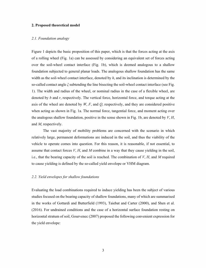
2. Proposed theoretical model
2.1. Foundation analogy
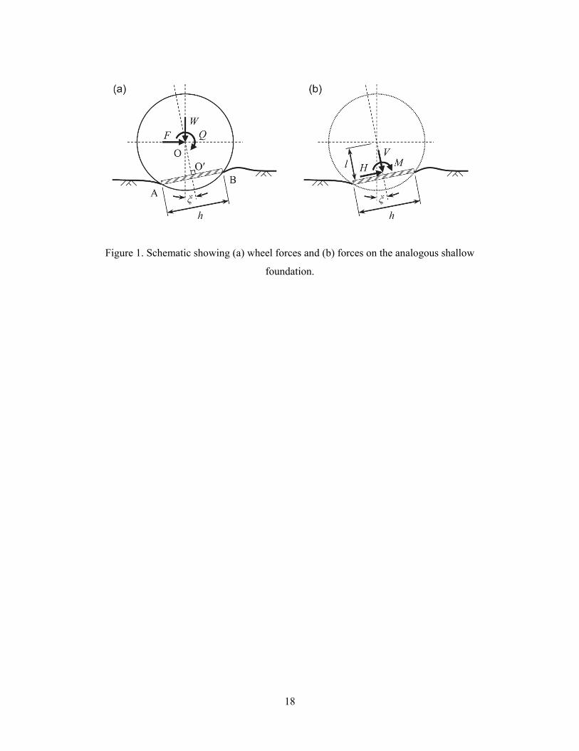
Figure 1 depicts the basic proposition of this paper, which is that the forces acting at the axis
of a rolling wheel (Fig. 1a) can be assessed by considering an equivalent set of forces acting
over the soil-wheel contact interface (Fig. 1b), which is deemed analogous to a shallow
foundation subjected to general planar loads. The analogous shallow foundation has the same
width as the soil-wheel contact interface, denoted by h, and its inclination is determined by the
so-called contact angle ξ subtending the line bisecting the soil-wheel contact interface (see Fig.
1). The width and radius of the wheel, or nominal radius in the case of a flexible wheel, are
denoted by b and r, respectively. The vertical force, horizontal force, and torque acting at the
axis of the wheel are denoted by W, F, and Q, respectively, and they are considered positive
when acting as shown in Fig. 1a. The normal force, tangential force, and moment acting over
the analogous shallow foundation, positive in the sense shown in Fig. 1b, are denoted by V, H,
and M, respectively.
The vast majority of mobility problems are concerned with the scenario in which
relatively large, permanent deformations are induced in the soil, and thus the viability of the
vehicle to operate comes into question. For this reason, it is reasonable, if not essential, to
assume that contact forces V, H, and M combine in a way that they cause yielding in the soil,
i.e., that the bearing capacity of the soil is reached. The combination of V, H, and M required
to cause yielding is defined by the so-called yield envelope or VHM diagram.
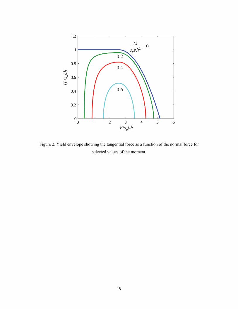
2.2. Yield envelopes for shallow foundations
Evaluating the load combinations required to induce yielding has been the subject of various
studies focused on the bearing capacity of shallow foundations, many of which are summarised
in the works of Gottardi and Butterfield (1993), Taiebat and Carter (2000), and Shen et al.
(2016). For undrained conditions and the case of a horizontal surface foundation resting on
horizontal stratum of soil, Gourvenec (2007) proposed the following convenient expression for
the yield envelope:
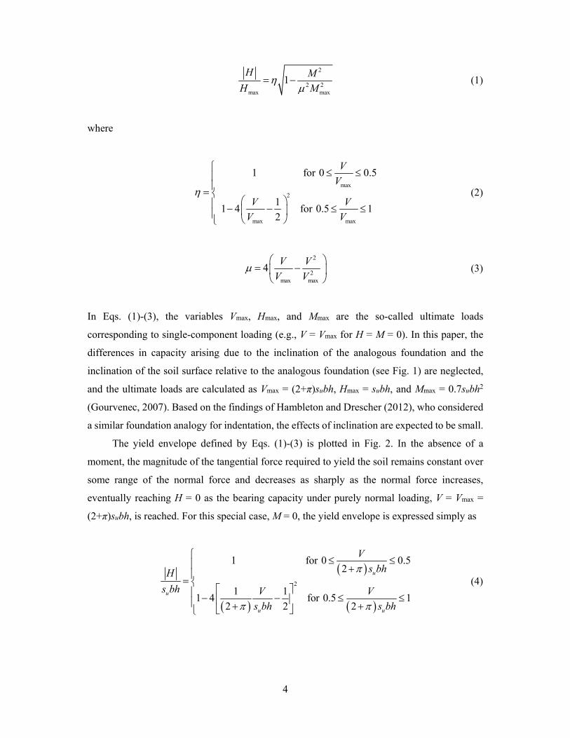
4
2
2 2max max
1H M
H M
(1)
where
max
2
max max
1 for 0 0.5
11 4 for 0.5 1
2
V
V
V V
V V
(2)
2
2max max
4V V
V V
(3)
In Eqs. (1)-(3), the variables Vmax, Hmax, and Mmax are the so-called ultimate loads
corresponding to single-component loading (e.g., V = Vmax for H = M = 0). In this paper, the
differences in capacity arising due to the inclination of the analogous foundation and the
inclination of the soil surface relative to the analogous foundation (see Fig. 1) are neglected,
and the ultimate loads are calculated as Vmax = (2+π)subh, Hmax = subh, and Mmax = 0.7subh2
(Gourvenec, 2007). Based on the findings of Hambleton and Drescher (2012), who considered
a similar foundation analogy for indentation, the effects of inclination are expected to be small.
The yield envelope defined by Eqs. (1)-(3) is plotted in Fig. 2. In the absence of a
moment, the magnitude of the tangential force required to yield the soil remains constant over
some range of the normal force and decreases as sharply as the normal force increases,
eventually reaching H = 0 as the bearing capacity under purely normal loading, V = Vmax =
(2+π)subh, is reached. For this special case, M = 0, the yield envelope is expressed simply as
2
1 for 0 0.52
1 11 4 for 0.5 1
2 2 2
u
u
u u
V
s bhH
s bh V V
s bh s bh
(4)
5
2.3. Equilibrium and closure conditions
Three additional equations relating the contact forces V, H, and M to the wheel forces W, F,
and Q are obtained considering static equilibrium:
cos sinW V H (5)
sin cosF V H (6)
sin cosQ M Wl Fl (7)
where l is the altitude given by
2
2
4
hl r (8)
In total, the yield envelope of Eq. (1) combined with the equations of equilibrium, Eqs. (5)-(7)
represent four equations that relate eight variables: the three wheel forces W, F, and Q; the
contact forces V, H, and M; the contact length h; and the contact angle ξ. Of the wheel forces,
two out of three must be specified in order to prescribe a well-posed problem. For example,
one may specify suitably normalised values for the vertical force and torque, W/subr and
Q/subr2 respectively, and then assess the corresponding horizontal force, H/subr, that develops.
A second case of practical interest would be to assess the torque required to achieve a particular
horizontal force given a value for the vertical force. Hence, the problem involves a total of six
unknowns, and one requires two additional equations or assumptions to arrive at a solution.
These additional requirements, or closure conditions, are discussed further in Section 5, after
considering existing analytical solutions (Section 3) and experimental data (Section 4).
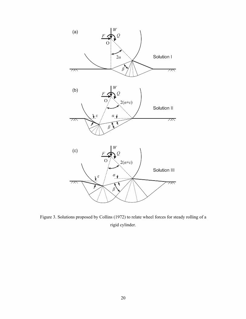
3. Analysis of steady rolling by Collins (1972)
In this section, the notion of regarding soil-wheel interaction as an equivalent foundation
problem involving general loading is assessed with respect to the analysis of a rolling rigid
cylinder completed by Collins (1972). His investigation rested on the assumption of steady
6
motion and the construction on deformation mechanisms that approximate the arc of contact
as a straight line, much like the foundation analogy depicted in Fig. 1. Base on the method of
characteristics (slip lines), the mechanisms proposed by Collins (1972), reproduced for
reference in Fig. 3, furnish approximate formulae relating the wheel forces W, F, and Q in
parametric form. These formulae vary in complexity, in some cases requiring a numerical
solution, and they are parameterised in terms of the angles α, β, and ε shown in Fig. 3, where
generally 2(α+ε) is the central angle defining the length of contact (ε = 0 in the mechanism of
Fig. 3a).
3.1. Predicted wheel forces
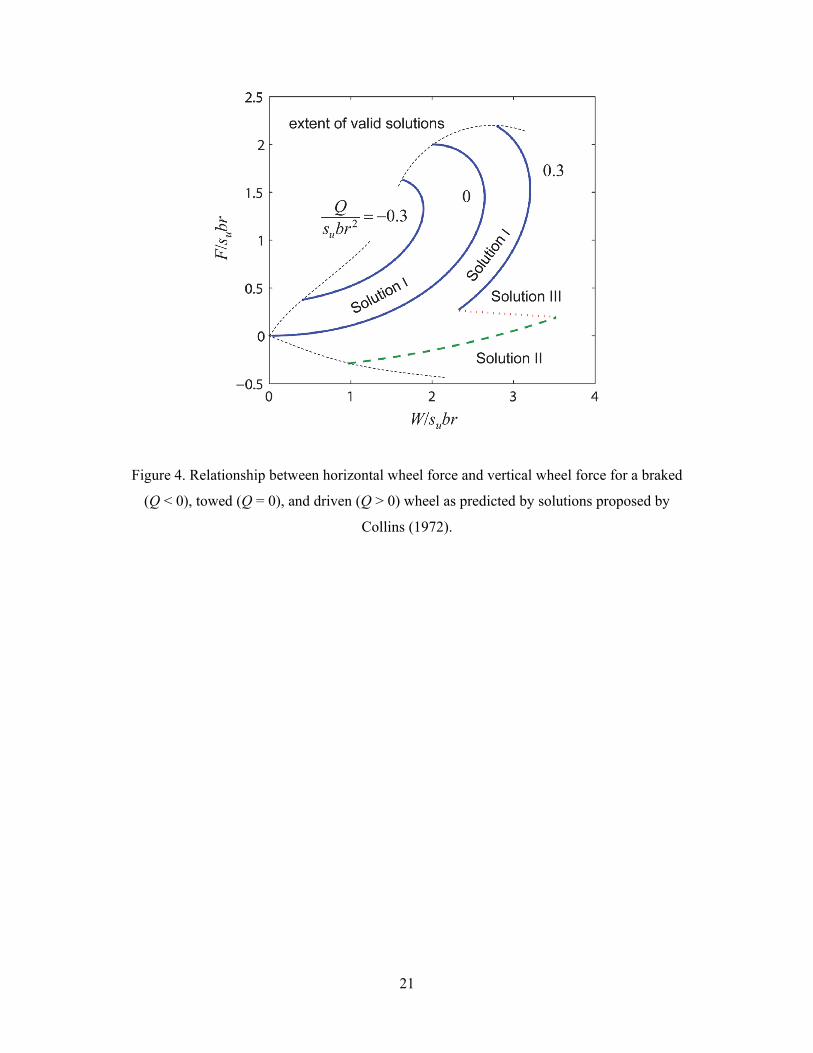
The relationship between the wheel forces predicted by Collins’ solutions is shown in Fig. 4.
Clearly, the curves take rather peculiar forms that vary distinctly as the torque ranges from Q
< 0 (braked wheel) to Q > 0 (driven wheel). For Q < 0 (braked wheel) and Q = 0 (towed wheel),
Solution I is the only applicable solution. For Q > 0 (driven wheel), all three solutions are
applicable, with Solution III being transitional between Solution I and Solution II. Irrespective
of the value of the torque Q, the solutions are valid only over some range of forces, the extents
of which are depicted qualitatively in Fig. 4. Outside these limits, the conditions governing the
validity of the solution, such as the condition that region of rigid material attached to the wheel
cannot be overstressed, prevent a solution from being constructed.
Perhaps the most peculiar aspect of the relationships plotted in Fig. 4 is that the functions
are multi-valued. For example, with W/subr = 3 and Q/subr2 = 0.3, four admissible values of
the normalised horizontal force F/subr, each corresponding to a different modes of deformation,
are predicted. This curious behaviour can be attributed to the approximation of the arc of
contact as a straight line, which in turn imposes specific constraints on the mechanisms used
to deduce the forces. Indeed, Collins (1972) asserted that these solutions are applicable only to
small contact angles, and for this reason he never plotted the solutions as shown in Fig. 4 but
rather explored various linearised forms of the resulting equations.
3.2. Contact forces, contact length, and contact angle
For the present study, the value of Collins’ solutions lies in the fact that the wheel forces,
contact length h = 2rsin(α+ε), and contact angle ξ = α are uniquely determined in each solution,
and therefore the relationships between the equivalent contact forces V, H, and M can be
7
determined directly from the equations of equilibrium, Eqs. (5)-(7). The contact moment M is
always zero in all cases by construction, a fact that is readily verified by computing M for each
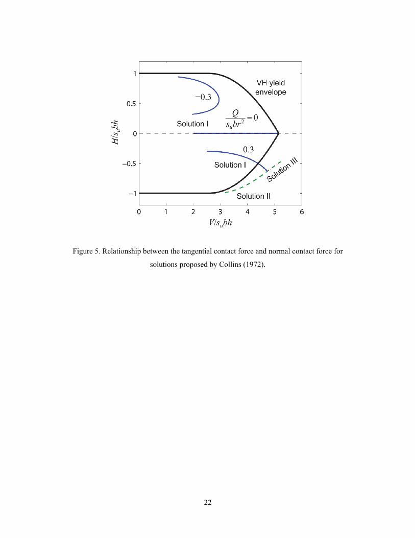
combination of wheel forces. It therefore suffices to plot the tangential contact force H against
the normal contact force V, as shown in Fig. 5, which also plots the yield envelope given by
Eq. (4). Plotted in this way, the curves corresponding to Collins’ solutions take a form that is
perhaps even more peculiar than that seen in Fig. 4. For example, in the case of the driven
wheel (Q > 0), Solution III yields values that are identical to those obtained from Solution II.
Overall, the solutions often fall well within the yield envelope from bearing capacity theory,
or well outside of it.
In view of the curious nature of the curves shown in Fig. 5, which again can be attributed
to the straight-line approximation for contact interface, attention is given to the emergent
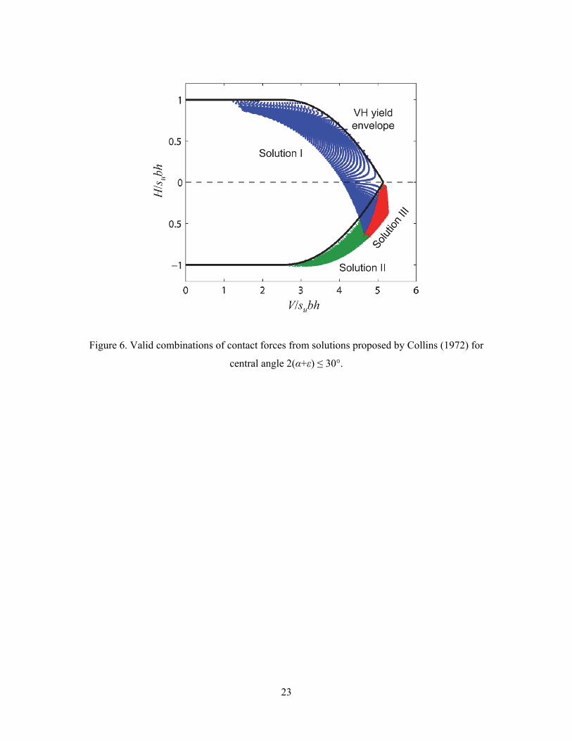
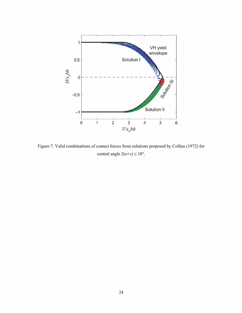
behaviour as the central angle 2(α+ε), or 2α for Solution I, becomes small. Figures 6 and 7
show the full extent of valid solutions over a range of wheel torques, −0.5 ≤ Q/subr2 ≤ 0.5,
considering limits on the central angle of 2(α+ε) ≤ 30° and 10°, respectively. One can observe
that as the central angle decreases, the solutions converge towards the yield envelope from
bearing capacity theory. Furthermore, the range of applicability of Solution III becomes
increasingly limited, although the necessity of the solution in attaining solutions close to the
apex of the yield envelope, H = 0 and V = Vmax = (2+π)subh, becomes apparent.
3.3. Implications
Based on the results shown in Figs. 5-7, one can conclude that Collins’ solutions definitively
support the analogy between rolling wheel and a shallow foundation subjected to general
loading when the contact length is small compared to the radius. When the contact length is
large, the analysis is inconclusive, as it is clear that the various mechanisms do not give
reasonable solutions. In all cases, the contact moment is zero, an assumption that will prove
useful in subsequent sections.
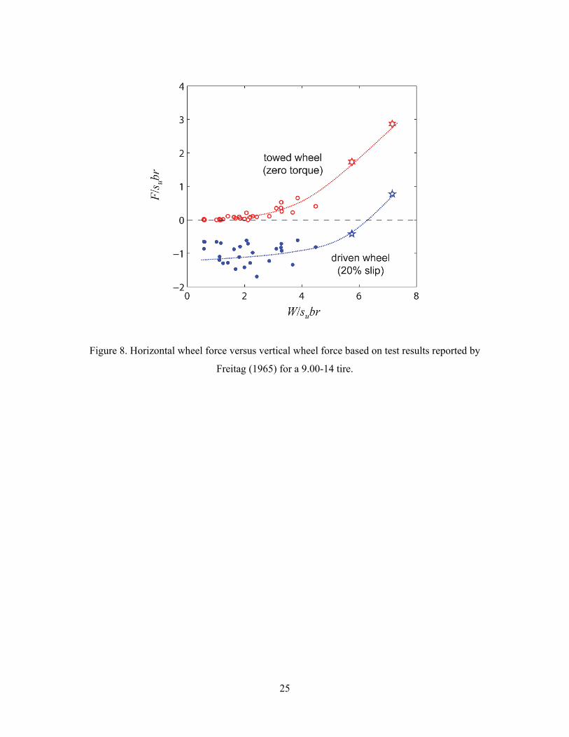
4. Laboratory tests by Freitag (1965)
The focus of this section is on the interpretation of the experimental data reported by Freitag
(1965), who measured the forces on pneumatic tyres operating on clay and sand under various
conditions. Freitag’s comprehensive report tabulates the wheel forces W, F, and Q measured
under steady rolling conditions for both a towed wheel (Q = 0) and a driven wheel, typically
8
with a controlled slip of s = 20% for clay. In Freitag’s study, the slip s is defined as s = 1 –
v/ωrr, where v is the linear wheel velocity, ω is the angular velocity, and rr is the so-called
rolling radius defined as the “forward advance per revolution of the loaded tire when towed on
a plane, level, unyielding surface, divided by 2π” (rr = r for a rigid wheel). A distinct feature
of the study is that the undrained shear strength of the clay su was determined through triaxial
testing. The measured strength, which ranged from su = 11 kPa to 36 kPa, correlated very well
to the values of cone index in the instances where both sets of measurements were taken, and
the latter were reported for each test.
4.1. Measured wheel forces
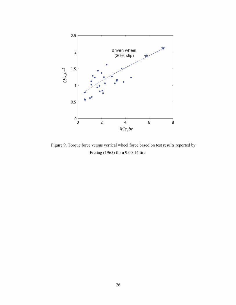
Figures 8 and 9 plot the wheel forces measured by Freitag (1965) using the dimensionless
variables from the previous figures. Upon comparison of Figs. 8 and Fig. 4, one observes that
the trends between the horizontal and vertical wheel forces are qualitatively similar to those
predicted by Collins (1972) for the towed (Q = 0) and driven (Q > 0) conditions. Quantitatively,
the experimental results differ significantly from the theoretical solutions. In particular, the
maximum values of normalised vertical force W/subr fall well outside the admissible range of
the theoretical solutions. Such a discrepancy is not surprising considering that wheel flexibility
and three-dimensional effects, both of which tend to increase the magnitude of the forces
involved, are not considered in Collins’ solutions. There are also likely to be significant viscous
effects occurring in the clay on the interface in the rolling experiments due to the higher strain
rates experienced in the tests compared to the triaxial tests used to characterise the undrained
strength. Typically such viscous effects result in an increase in operative undrained strength of
~5-20% per logarithmic cycle of strain rate (e.g., Biscontin and Pestana, 2001). If the operative
strength in Freitag’s experiments was higher than measured in the corresponding triaxial tests
due to strain rate effects, the normalised quantities in Fig. 8 would decrease, causing the
measurements to tend closer to Collins’ solutions.
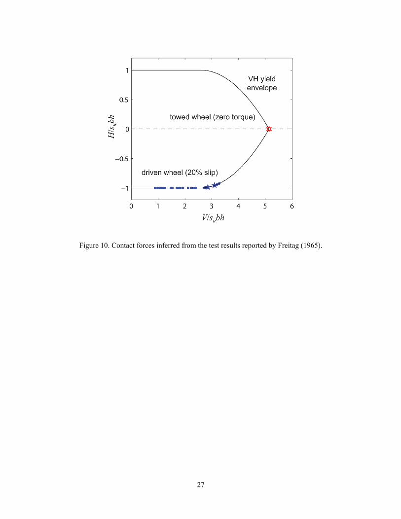
4.2. Contact forces, contact length, and contact angle
Alone, the data reported by Freitag (1965) are insufficient to ascertain the relationship between
the contact forces V, H, and M. In particular, no information regarding the contact length h or
contact angle ξ is available for any of the tests. However, if one assumes M = 0 in consistence
with the solutions by Collins (1972), the yield condition of Eq. (4) together with the three
9
equations of equilibrium, Eqs. (5)-(7), are sufficient to compute the four unknowns V, H, h,
and ξ. With M = 0, Eq. (7) reduces to
2
2
4
hQ Hl H r Hr (9)
The approximation indicated in Eq. (9) is introduced not only to simplify the calculations but
also in recognition of the fact that, for a flexible wheel, the contact length h, nominal wheel
radius r, and altitude l may not be as strongly coupled as Eq. (8) would imply.
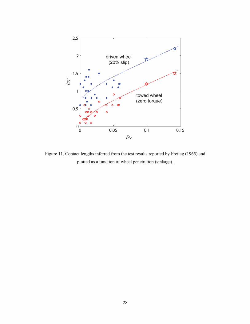
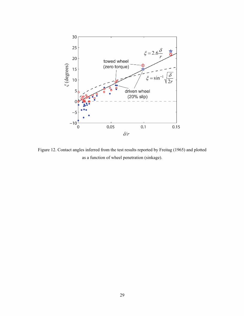
Figures 10-12 show the values of the normal contact force V, horizontal contact force H,
contact length h, and contact angle ξ inferred from the test results. The contact forces plotted
in Fig. 10 all lie precisely on the yield envelope as a result of having exactly as many equations
as unknowns. For the towed wheel, the contact forces are given in all cases by H = 0 and V =
Vmax = (2+π)subh as a direct consequence of Eq. (9), and thus the data are all gathered at the
apex of the yield envelope. In contrast, the contact forces for the driven wheel are widely
distributed across the envelope. As one might expect, the tests with the largest values of the
normalised vertical force, marked by stars in Figs. 8-12, tend to produce values of the contact
normal force that lie on the portion of the yield envelope over which the tangential contact
force decreases. In other words, these points approach the capacity of the soil under purely
normal loading. In Figs. 11 and 12, the inferred values of h and ξ are plotted against the
corresponding values of wheel penetration, or so-called sinkage, measured by Freitag (1965),
revealing fairly well-defined trends that degenerate as the penetration decreases.
4.3. Implications
While not entirely conclusive, the trends visible in Figs. 11 and 12 provide some level of
validation of the theoretical framework proposed in this paper. Namely, one should expect that
both the contact length and the contact angle should increase with increasing wheel penetration,
and this expectation is fully met in Figs. 11 and 12. Likewise, the diminishing strength of the
correlations for small wheel penetration is unsurprising given the well-known indeterminacy
of the contact length for flexible wheels operating in soft soils (cf. Fujimoto, 1977; Hambleton
and Drescher, 2008). On the other hand, while the trends are apparent, the inferred contact
lengths are too large to be considered realistic. This overestimation of the contact length is
10
consistent with the discrepancy noted in comparing the experimental data to the solutions
proposed by Collins (1972). While the influence of wheel flexibility is, to some extent,
accounted for in the back-calculation of the contact length, three-dimensional effects are
wholly neglected, and these effects may lead to an overestimation of the contact length through
a commensurate underestimation of the forces involved. As observed earlier, the operating
shear strength may also be underestimated, which would tend to result in an overestimation of
the back-calculated contact lengths.
5. Model summary
5.1. Model implementation
The most straightforward means of implementing the proposed model is to specify the contact
length h and contact angle ξ directly, and then to assess the wheel forces W, F, and Q from Eqs.
(4)-(7), recognizing that Eq. (4) implicitly utilises the assumption that the contact moment M
is zero. Results from the previous section suggest that both h and ξ relate strongly to the wheel
penetration (sinkage), and this is well supported by findings from previous studies. In
particular, the validity of this relationship for a towed wheel was demonstrated by Hambleton
and Drescher (2008, 2009a, 2012), who also reflected on the pathological nature of the two-
dimensional problem as compared to the three-dimensional problem (2009b). For steady
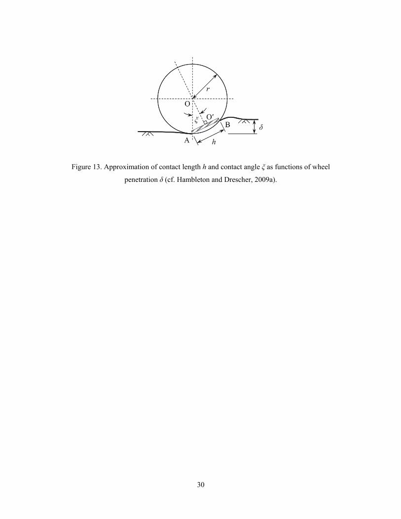
motion of a towed, rigid wheel, the contact length is approximated as the chord length spanning
the lowermost part of the wheel and the point of intersection with undisturbed soil surface, as
shown in Fig. 13 (cf. Hambleton and Drescher, 2009a):
2h r (10)
The corresponding contact angle is given by
1sin2
r (11)
11
Equation (11) is plotted together with the data of Freitag (1965) in Fig. 12, which shows that
Eq. (11) generates contact angles reasonably close to the experimental results. The apparent
deviations, especially at low values of wheel penetration, are to be expected considering the
flexibility of the tyre used in the tests.
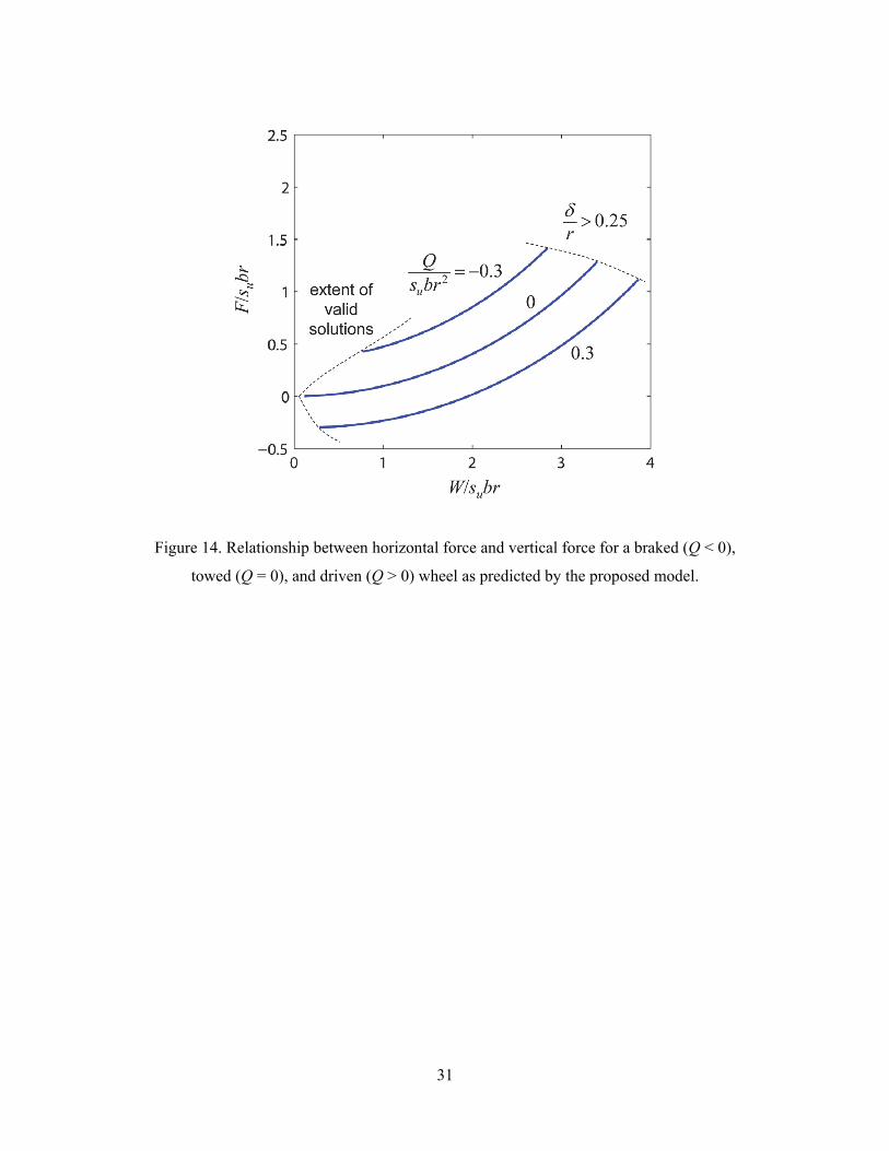
Predictions of the wheel forces obtained with the proposed model, given by combining
Eqs. (4)-(6) and Eqs. (8)-(11), are plotted in Fig. 14. Overall, the curves are similar to those
shown in Fig. 4 for the solutions proposed by Collins (1972). The curves from the proposed
model exhibit smaller curvature and, most notably, a single-valued nature for all possible
values of the wheel torque. In Fig. 14, the curves are bounded on the lower left by the physical
condition that the horizontal contact force H cannot exceed the maximum Hmax = subh, and they
are bounded on the upper right by an arbitrarily selected restriction on the wheel penetration
(sinkage) of δ ≤ r/4, imposed in recognition of the model’s limitations as the penetration
becomes large. It should be emphasised that all of the predictions, parameterised in terms of
the normalised wheel penetration δ/r, are plotted based on the same set of equations, and thus
the model provides a single comprehensive framework for addressing each of the various cases
(driven, braked, and towed).
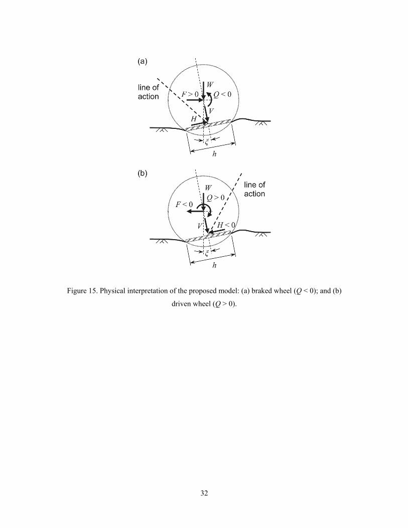
5.2. Physical interpretation
As depicted in Fig. 15, the proposed model also provides a natural physical interpretation of
the mobility problem. The assumption that the contact moment M is zero requires that the line
of action of resultant contact force passes through the centre of the equivalent foundation, and
this line of action passes either behind the centre of the wheel when braked (Fig. 14a) or in
front of the wheel’s centre when driven (Fig. 14b). For a towed wheel, the line of action passes
directly through the wheel’s centre. In each case, the magnitude of the contact forces is dictated
directly by the yield envelope.
6. Conclusions
The basic proposition of this paper is that the forces developing on a rolling wheel operating
on soft soil can be assessed by considering an equivalent shallow foundation subjected to
general planar loading. Combined with suitable estimates for the two primary geometric
variables appearing in the model, the contact length h and contact angle ξ, this analogy leads
to a comprehensive yet simple theoretical framework for predicting wheel forces in any
12
operating condition (driven, braked, and towed). Namely, Eqs. (4)-(6) and (8)-(11) constitute
a complete theoretical model for predicting the wheel forces W, F, and Q from three
fundamental inputs: the undrained shear strength of the soil su, the wheel width b, and the wheel
radius r. The model is parametrized in terms of the wheel penetration (sinkage) δ, which is not
required as an input but nevertheless imposes limits on the range of validity of the solution, as
illustrated in Fig. 14.
While the proposed model remains to be fully validated by laboratory and field tests in
which the length and position of the contact interface are somehow determined, initial
comparisons with existing analytical solutions and experimental data provide a partial
validation. Attention in this study was directed at the two-dimensional (plane strain) problem
and fine-grained soils exhibiting undrained behaviour, but the potential to extend the model to
other materials (e.g., sand) is evident. Indeed, a key aspect of the proposed model is that it takes
direct advantage of the relatively mature body of knowledge pertaining to the bearing capacity
of shallow foundations. Existing works on the bearing capacity of three-dimensional problems
(e.g., Gourvenec, 2007) may prove very useful in refining the model to obtain quantitative as
well as qualitative agreement with laboratory data for narrow wheels, such as that reported by
Freitag (1965).
A key assumption utilised repeatedly in this study, and implemented implicitly in the
solutions proposed by Collins (1972), is that the contact moment is zero. This simplifies the
computations considerably, but an open question remains as to whether this assumption is
correct. The proposed model can easily account for the effect of a non-zero moment, provided
it can be estimated.
Acknowledgements
The authors gratefully acknowledge the financial support provided by the Australian Research
Council (ARC) through the ARC Centre of Excellence for Geotechnical Science and
Engineering (CE110001009). The first author also acknowledges support from an ARC
Discovery Early Career Research Award (DE160100328).
References
Asaf, Z., Shmulevich, I., and Rubinstein, D. (2006). Predicting soil-rigid wheel performance
using distinct element methods. Transactions of the ASABE, 49(3), 607-616.
13
Bekker, M.G. (1956). Theory of Land Locomotion, University of Michigan Press, Ann Arbor.
Bekker, M.G. (1960). Off-the-Road Locomotion, University of Michigan Press, Ann Arbor.
Bekker, M.G. (1969). Introduction to Terrain-Vehicle Systems, University of Michigan Press,
Ann Arbor.
Biscontin, G., and Pestana, J.M. (2001). Influence of peripheral velocity on vane shear strength
of an artificial clay. Geotechnical Testing Journal, 24(4), 3423-429.
Chiroux, R.C., Foster, W.A., Johnson, C.E., Shoop, S.A., and Raper, R.L. (2005). Three-
dimensional finite element analysis of soil interaction with a rigid wheel. Applied
Mathematics and Computation, 162(2), 707-722.
Collins, I.F. (1972). A simplified analysis of the rolling of a cylinder on a rigid/perfectly plastic
half-space. International Journal of Mechanical Sciences, 14(1), 1-14.
Collins, I.F. (1978). On the rolling of a rigid cylinder on a rigid/perfectly plastic half-space.
Journal de Mécanique appliquée, 2(4), 431-448.
Dagan, G., and Tulin, M.P. (1969). A study of the steady flow of a rigid-plastic clay beneath a
driven wheel. Journal of Terramechanics, 6(2), 9-27.
Ding, L., Gao, H., Deng, Z., Li, Y., and Liu, G. (2014). New perspective on characterizing
pressure-sinkage relationship of terrains for estimating interaction mechanics. Journal of
Terramechanics, 52, 57-76.
Fervers, C.W. (2004). Improved FEM simulation model for tire-soil interaction. Journal of
Terramechanics, 41(2-3), 87-100.
Freitag, D.R. (1965). A Dimensional Analysis of the Performance of Pneumatic Tires on Soft
Soils, Technical Report No. 3-688, US Army Engineer Waterways Experiment Station,
Vicksburg.
Fujimoto, Y. (1977). Performance of elastic wheels on yielding cohesive soils. Journal of
Terramechanics, 14(4), 191-210.
Gallina, A., Krenn, R., and Schäfer, B. (2016). On the treatment of soft soil parameter
uncertainties in planetary rover mobility simulations. Journal of Terramechanics, 63, 33-
47.
Gottardi, G., and Butterfield, R. (1993). On the bearing capacity of surface footings on sand
under general planar loads. Soils and Foundations, 33(3), 68-79.
Gourvenec, S. (2007). Shape effects on the capacity of rectangular footings under general
loading. Géotechnique, 57(8), 637-646.
Gray, J.P., Vantsevich, V. V., and Paldan, J. (2016). Agile tire slippage dynamics for radical
enhancement of vehicle mobility. Journal of Terramechanics, 65, 14-37.
14
Hambleton, J.P. and Drescher, A. (2008). Development of Improved Test Rolling Methods for
Roadway Embankment Construction—Final Report, Minnesota Department of
Transportation, Research Services Section, St. Paul.
Hambleton, J.P., and Drescher, A. (2009a). Modeling wheel-induced rutting in soils: Rolling.
Journal of Terramechanics, 46(2), 34-47.
Hambleton, J.P., and Drescher, A. (2009b). On modeling a rolling wheel in the presence of
plastic deformation as a three- or two-dimensional process. International Journal of
Mechanical Sciences, 51(11-12), 846-855.
Hambleton, J.P., and Drescher, A. (2012). Approximate model for blunt objects indenting
cohesive-frictional material. International Journal for Numerical and Analytical
Methods in Geomechanics, 36(3), 249-271.
Higa, S., Nagaoka, K., Nagatani, K., and Yoshida, K. (2015). Measurement and modeling for
two-dimensional normal stress distribution of wheel on loose soil. Journal of
Terramechanics, 62, 63-73.
Johnson, J.B., Kulchitsky, A.V., Duvoy, P., Iagnemma, K., Senatore, C., Arvidson, R.E., and
Moore, J. (2015). Discrete element method simulations of Mars Exploration Rover wheel
performance. Journal of Terramechanics, 62, 31-40.
Liu, C.H., and Wong, J.Y. (1996). Numerical simulations of tire-soil interaction based on
critical state soil mechanics. Journal of Terramechanics, 33(5), 209-221.
Karafiath, L.L., Nowatzki, E.A. (1978). Soil Mechanics for Off-road Vehicle Engineering,
Trans Tech Publications, Clausthal.
Maclaurin, B. (2007). Comparing the NRMM (VCI), MMP and VLCI traction models. Journal
of Terramechanics, 44, 43-51.
Marshall, E.A. (1968). Rolling contact with plastic deformation. Journal of the Mechanics and
Physics of Solids, 16(4), 243-254.
Mason, G.L., Vahedifard, F., Robinson, J.D., Howard, I.L., McKinley, G.B., and Priddy, J.D.
(2016). Improved sinkage algorithms for powered and unpowered wheeled vehicles
operating on sand. Journal of Terramechanics, 67, 25-36.
Modenese, C. (2013). Numerical Study of the Mechanical Properties of Lunar Soil by the
Discrete Element Method. PhD Thesis. University of Oxford, Oxford.
Nishiyama, K., Nakashima, H., Yoshida, T., Ono, T., Shimizu, H., Miyasaka, J., and Ohdoi,
K. (2016). 2D FE–DEM analysis of tractive performance of an elastic wheel for planetary
rovers, Journal of Terramechanics, 64, 23-35.
15
Osetinsky, A., and Shmulevich, I. (2004). Traction performance simulation of a pushed/pulled
driven wheel. Transactions of the ASAE, 47(4), 981-994.
Ozaki, S., and Kondo, W. (2016). Finite element analysis of tire traveling performance using
anisotropic frictional interaction model. Journal of Terramechanics, 64, 1-9.
Petryk, H. (1983). Slip-line field analysis of the rolling contact problem at high loads.
International Journal of Mechanical Sciences, 25(4), 265-275.
Priddy, J.D. (1999). Improving the Traction Prediction Capabilities in the NATO Reference
Mobility Model (NRMM), Technical Report No. GL-99-8, US Army Engineer
Waterways Experiment Station, Vicksburg.
Shen, Z., Feng, X., and Gourvenec, S. (2016). Undrained capacity of surface foundations with
zero-tension interface under planar V-H-M loading. Computers and Geotechnics, 73, 47-
57.
Shibly, H., Iagnemma, K., and Dubowsky, S. (2005). An equivalent soil mechanics formulation
for rigid wheels in deformable terrain, with application to planetary exploration rovers.
Journal of Terramechanics, 42(1), 1-13.
Shoop, S.A., Richmond, P.W., and Lacombe, J. (2006a). Overview of cold regions mobility
modeling at CRREL. Journal of Terramechanics, 43(1), 1-26.
Shoop, S.A., Haehnel, R., Janoo, V., Harjes, D., and Liston, R. (2006b). Seasonal deterioration
of unsurfaced roads. Journal of Geotechnical and Geoenvironmental Engineering,
132(7), 852-860.
Taiebat, H.A, and Carter, J.P. (2000). Numerical studies of the bearing capacity of shallow
foundations on cohesive soil subjected to combined loading. Géotechnique, 50(4), 409-
418.
Tordesillas, A., and Shi, J. (2000). Frictionless rolling contact of a rigid circular cylinder on a
semi-infinite granular material. Journal of Engineering Mathematics, 37(1-3), 231-252.
Vahedifard, F., Robinson, J.D., Mason, G.L., Howard, I.L., and Priddy, J.D. (2016). Mobility
algorithm evaluation using a consolidated database developed for wheeled vehicles
operating on dry sands. Journal of Terramechanics, 63, 13-22.
Xiao, W., and Zhang, Y. (2016). Design of manned lunar rover wheels and improvement in
soil mechanics formulas for elastic wheels in consideration of deformation. Journal of
Terramechanics, 65, 61-71.
Yong, R.N., Fattah, E.A., and Boonsinsuk, P. (1978). Analysis and prediction of tyre-soil
interaction and performance using finite elements. Journal of Terramechanics, 15(1), 43-
63.

16
17
Figure Captions
Figure 1. Schematic showing (a) wheel forces and (b) forces on the analogous shallow foundation. Figure 2. Yield envelope showing the tangential force as a function of the normal force for selected values of the moment. Figure 3. Solutions proposed by Collins (1972) to relate wheel forces for steady rolling of a rigid cylinder. Figure 4. Relationship between horizontal wheel force and vertical wheel force for a braked (Q < 0), towed (Q = 0), and driven (Q > 0) wheel as predicted by solutions proposed by Collins (1972). Figure 5. Relationship between the tangential contact force and normal contact force for solutions proposed by Collins (1972). Figure 6. Valid combinations of contact forces from solutions proposed by Collins (1972) for central angle 2(α+ε) ≤ 30°. Figure 7. Valid combinations of contact forces from solutions proposed by Collins (1972) for central angle 2(α+ε) ≤ 10°. Figure 8. Horizontal wheel force versus vertical wheel force based on test results reported by Freitag (1965) for a 9.00-14 tire. Figure 9. Torque force versus vertical wheel force based on test results reported by Freitag (1965) for a 9.00-14 tire. Figure 10. Contact forces inferred from the test results reported by Freitag (1965). Figure 11. Contact lengths inferred from the test results reported by Freitag (1965) and plotted as a function of wheel penetration (sinkage). Figure 12. Contact angles inferred from the test results reported by Freitag (1965) and plotted as a function of wheel penetration (sinkage). Figure 13. Approximation of contact length h and contact angle ξ as functions of wheel penetration δ (cf. Hambleton and Drescher, 2009a). Figure 14. Relationship between horizontal force and vertical force for a braked (Q < 0), towed (Q = 0), and driven (Q > 0) wheel as predicted by the proposed model. Figure 15. Physical interpretation of the proposed model: (a) braked wheel (Q < 0); and (b) driven wheel (Q > 0).
18
Figure 1. Schematic showing (a) wheel forces and (b) forces on the analogous shallow
foundation.
19
Figure 2. Yield envelope showing the tangential force as a function of the normal force for
selected values of the moment.
20
Figure 3. Solutions proposed by Collins (1972) to relate wheel forces for steady rolling of a
rigid cylinder.
21
Figure 4. Relationship between horizontal wheel force and vertical wheel force for a braked
(Q < 0), towed (Q = 0), and driven (Q > 0) wheel as predicted by solutions proposed by
Collins (1972).
22
Figure 5. Relationship between the tangential contact force and normal contact force for
solutions proposed by Collins (1972).
23
Figure 6. Valid combinations of contact forces from solutions proposed by Collins (1972) for
central angle 2(α+ε) ≤ 30°.
24
Figure 7. Valid combinations of contact forces from solutions proposed by Collins (1972) for
central angle 2(α+ε) ≤ 10°.
25
Figure 8. Horizontal wheel force versus vertical wheel force based on test results reported by
Freitag (1965) for a 9.00-14 tire.
26
Figure 9. Torque force versus vertical wheel force based on test results reported by
Freitag (1965) for a 9.00-14 tire.
27
Figure 10. Contact forces inferred from the test results reported by Freitag (1965).
28
Figure 11. Contact lengths inferred from the test results reported by Freitag (1965) and
plotted as a function of wheel penetration (sinkage).
29
Figure 12. Contact angles inferred from the test results reported by Freitag (1965) and plotted
as a function of wheel penetration (sinkage).
30
Figure 13. Approximation of contact length h and contact angle ξ as functions of wheel
penetration δ (cf. Hambleton and Drescher, 2009a).
31
Figure 14. Relationship between horizontal force and vertical force for a braked (Q < 0),
towed (Q = 0), and driven (Q > 0) wheel as predicted by the proposed model.
32
Figure 15. Physical interpretation of the proposed model: (a) braked wheel (Q < 0); and (b)
driven wheel (Q > 0).