Embed Size (px)
Citation preview

B. Kokotović, M. Glavonjić Predviđanje sila glodanja u virtualnom obradnom sustavu
ISSN 1330-3651 (Print), ISSN 1848-6339 (Online) UDC/UDK 621.914:[531.78:004.942]
PREDICTING OF MILLING FORCES IN A VIRTUAL MANUFACTURING SYSTEM Branko Kokotović, Miloš Glavonjić
Original scientific paper Forces prediction along the tool path is one of the basic goal functions of the virtual machining system for CNC milling operations. In this paper, the discussion is limited to the contour milling in the plane z=const, using the flat end mills. Predictions are based on the simulation of the instant values of the milling force components during one tool revolution. Simulation uses discretized cutting geometry (discs) of end mill. This paper presents two approaches for reconstruction of tool/workpiece contact area. The first one implies the approximation of the workpiece volume using the z-map. The second presented approach calculates entry/exit angles at the 2D milling operations with the constant depth. Reconstruction of these angles is based on the analysis of previously formed radial stock and description of the tool path. Presented procedures for the predicting of milling forces have been implemented in the Matlab. Results of experimental verification of the proposed procedures are presented. Keywords: cutting forces, milling, prediction, simulation, virtual machining Predviđanje sila glodanja u virtualnom obradnom sustavu
Izvorni znanstveni članak Predviđanje sila duž putanje alata jedna je od osnovnih funkcija cilja virtualnog obradnog sustava za operacije CNC glodanja. U ovom radu, razmatranje je ograničeno na glodanje kontura u ravnini z=const, ravnim vretenastim glodalima. Predviđanja se zasnivaju na simulaciji trenutnih vrijednosti komponenata sile glodanja na jednom okretaju alata. U simulaciji se koristi diskretizirana rezna geometrija (diskovi) vretenastog glodala. Predstavljena su dva pristupa za rekonstruiranje kontaktne površine alata i radnog predmeta. Prvi pristup podrazumijeva aproksimaciju obujma obratka pomoću z-mape. Drugi predstavljeni pristup odnosi se na izračunavanje ulaznih/izlaznih kutova zahvata u operacijama 2D obrade glodanjem, pri konstantnoj dubini. Rekonstrukcija tih kutova zasniva se na poznavanju prethodno formiranog bočnog dodatka za obradu i na opisu putanje alata. Predstavljene procedure predviđanja sila glodanja su implementirane u Matlab okruženju. Pokazani su rezultati eksperimentalne verifikacije predloženih procedura. Ključne riječi: glodanje, predviđanje, sile rezanja, simulacija, virtualna obrada 1 Introduction
For more than last two decades, software environment has been developed in different areas of engineering, which should provide pseudo-real experience of behavior of the designed object or process. In the area of production engineering such a research direction is recognized today as the Virtual Machine Tool (VMT), Virtual Machining (VM), Virtual Inspection (VI), etc. The concepts of VMT and VM [1] are often entangled. Yet, VMT techniques development is primarily the outcome of the machine tools manufacturers’ interest [2], as a solution for increasing the quality of the designed machine, with imperative to reduce the development costs. VM concept implies models of hardware elements of manufacturing systems and machining processes, and its aim is the prediction and optimization of designed manufacturing process. The prediction and optimization refer, directly or indirectly, to the attributes of a machined part, but as well to the effects on other entities of the manufacturing system [3]. Finally, VM goal functions implicitly or explicitly reflect techno-economic criteria [4].
For cutting operations on the CNC machine tools and virtual machining environment (VM) it is necessary to ensure the prediction of: (i) cutting forces, (ii) vibrations and (iii) temperatures in the cutting zone. Technology redesigning implies goal functions which ensure keeping of these values within certain limits. This paper is focused to the force predicting. Obtained predictions, for particular conditions and part program are the outcome by themselves, as a strong feedback in the process of technology designing. On the other side reliable force
predictions are the basis for the off-line federate optimization along the tool path.
Section 2 of the paper describes the procedure, which in VM provides predictions of milling force components in 2D contour milling operations, with flat end mills. The workpiece model in the form of the z-map allows application also in conditions of significant variation of the shape of tool/workpiece contact area. The contents of static and dynamic database, as well as functional modules are described. Also, an example of contour milling, with the experimental verification (milling test) of presented procedure is shown.
Section 3 includes the force predicting procedure for final milling operations of contours in plane z=const at the constant depth. Most of the modules have identical function as in the Section 2, including the specific reconstruction method of the tool contact area. This procedure is illustrated by two examples of the contour milling, with experimental verification of the predictions. 2 Predicting of milling forces along the programmed tool
path using the z-map model of the workpiece
One of important building elements of VM environment is its database. This paper deploys a part of research results in the domain of the architecture of intelligent systems for the real time control. According to [5] knowledge database is data structure with static and dynamic information, which together create the world model. Information from the database is organized as: entity frames, system parameters, state variables and maps. The frame (generic or specific) is a structure formed as the list of attributes of a particular entity. The state variables specify instant attribute values of specific
Tehnički vjesnik 20, 6(2013), 1027-1035 1027

Predicting of milling forces in a virtual manufacturing system B. Kokotović, M. Glavonjić
entity or whole system. The system parameters specify dynamic properties of a controlled object or process, in the form of the constants or fixed procedures. The maps are specific descriptive forms of a particular entity in space. Database of the VM environment, discussed in this paper, includes: • The tool frame with attributes (tool profile) necessary
for updating of the workpiece volume and with cutting geometry attributes, required for cutting forces prediction at the elements of cutting edges.
• The workpiece map. This paper deploys the digital interpretation of workpiece volume in the form of z-map [6]
• The frame of the tool path element includes the attributes of path element described by one block (G01/G02/G03) in the part program and attributes such as programmed spindle speed and feed rate.
• The frame of the point on the tool path. A set of points is formed by the discretizing of tool path element. Each point is associated with its coordinates and the actual feed rate vector direction.
• The tool engagement map describes part of the tool envelope which is in contact with the workpiece, in the particular point of the discretized tool path.
• The force map is an output of the VM environment for predicting milling forces. It consists of the predicted representative values of milling force components associated with the points of discretized tool path.
• The system parameters necessary for milling forces predicting are specific cutting forces (force coefficients) for the actual workpiece material and cutting geometry of the mill.
There are two coordinate systems to be defined. One is the fixed coordinate system of the workpiece Oxwywzw, with the origin at zero point of the workpiece. The other one, the moving coordinate system Oxyz, has its origin on the top of the mill. In the actual point of the discretized path it is oriented by the feed-rate vector (vf) and spindle axis (z), as shown in Fig.1a.
Figure 1 Discretized cutting length of the flat end mill (a),
Disc of the differential thickness (b), Differential cutting forces in oblique cutting on the differential length of the cutting edge (c)
2.1 Procedure for force map construction
The procedure for force map construction for the programmed tool path has modular structure. The module used for predicting profiles of instant values of the milling force components (module sim1rev), at one revolution of the discretized cutting length of the mill [7] as shown in Fig. 1a
For the flat end mill with the nominal radius Rt, with i = 1 ÷ Nf flutes and with j = 1 ÷ Nd discs of thickness dz on the active mill length, differential cutting forces on the elementary cutting edge (i, j) are:
),dd)(()(d),dd)(()(d),dd)(()(d
aesaca
resrcr
testct
LKzj,ihKmuj,iFLKzj,ihKmuj,iFLKzj,ihKmuj,iF
+=+=+=
(1)
where:
1=u for π]0[)( ,j,i ∈ϕ , 0=u for π).2(π)( ,j,i ∈ϕ Indicator m (0 or 1) indicates engagement of edge
element in position )(),,( jzjiϕ . For the elementary part of the edge with the angular position ),( jiϕϕ = (Fig. 1c) the contribution to the milling force components, along the coordinate axes is:
).(d)d
,)cos(d)sin(d)(d,)sin(d)cos(d)(d
a
rt
rt
j,iFj,(iF
j,iFj,iFj,iFj,iFj,iFj,iF
z
y
x
=
−−=+−=
ϕϕϕϕ
(2)
The force components acting on the whole mill are obtained by integration:
.,)(d
, )(d,)(d
22f
1
d
1a
f
1
d
1
f
1
d
1
yxxy
N
i
N
jz
N
i
N
jxy
N
i
N
jxx
FFFj,iFF
j,iFFj,iFF
+==
==
∑∑
∑∑∑∑
= =
= == =
(3)
Resulting torque is:
. )(df
1
d
1tt∑∑
= =
=N
i
N
jz j,iFRM
(4)
The uncut chip thickness for the elementary edge length i and the disc j is obtained approximately as:
).()sin()( max ss j,ij,ihj,ih ϕ= (5) For the mill runout in accordance with [8] two parameters as shown in Fig. 2 are to be used:
rρ (mm) offset of the axis of the fluted mill length from the axis of rotation and
rθ (rad) angular position of rρ from the referent tooth on the top of the mill (point S, Fig. 2a).
For the elementary cutting edge with the angular position
),( jiθθ = mesured from the referent tooth on the top of the mill, the actual rotating radius (Fig. 2a) will be:
.)(sin)cos()( r22
r2trr θθρθθρ −−+−= Rj,ir (6)
Each elementary cutting edge will have calculated maximum uncut chip thickness (Fig. 2b):
1028 Technical Gazette 20, 6(2013), 1027-1035
B. Kokotović, M. Glavonjić Predviđanje sila glodanja u virtualnom obradnom sustavu
.1),()1()1(,2),1()()(
fzmax s
fzmax s
=−+=÷=−−+=
ij,Nrj,rsj,hNij,irj,irsj,ih
(7)
Figure 2 Runout parameters (a) and max. uncut chip thickness (b) of the elementary cutting edges of one disc
In case that (7) result in a negative value for hs max(i,j), the simulation is to be performed with hs max(i,j)=0.
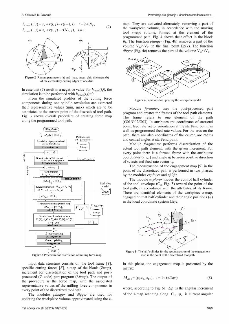
From the simulated profiles of the cutting force components during one spindle revolution are extracted their representative values (min, max) which are to be associated to the current point of the discretized tool path. Fig. 3 shows overall procedure of creating force map along the programmed tool path.
Figure 3 Procedure for costruction of milling force map
Input data structure consists of: the tool frame [T], specific cutting forces [K], z-map of the blank (Zmap), increment for discretization of the tool path and post-processed (G code) part program (Mmap). The output of the procedure is the force map, with the associated representative values of the milling force components in every point of the discretized tool path.
The modules plunger and digger are used for updating the workpiece volume approximated using the z-
map. They are activated alternately, removing a part of the workpiece volume, in accordance with the moving tool swept volume, formed at the element of the programmed path. Fig. 4 shows their effect in the block Bk. The function plunger (Fig. 4b) removes a part of the volume VW∩VT in the final point Ep(k). The function digger (Fig. 4c) removes the part of the volume VW∩VE.
Figure 4 Functions for updating the workpiece model
Module formater, uses the post-processed part program and creates the frames of the tool path elements. The frame refers to one element of the path (G01/G02/G03). Its attributes are: coordinates of start/end point, feed rate vector orientation at the start/end point, as well as programmed feed rate values. For the arcs on the path, there are also coordinates of the center, arc radius and central angles at start/end point.
Module fragmenter performs discretization of the actual tool path element, with the given increment. For every point there is a formed frame with the attributes: coordinates (x,y,z) and angle ηf between positive direction of xw axis and feed-rate vector vf.
The reconstruction of the engagement map [9] in the point of the discretized path is performed in two phases, by the modules explorer and zfi2fiz.
The module explorer moves the control half cylinder of the tool envelope (CH, Fig. 5) toward the point of the tool path, in accordance with the attributes of its frame. There are identified elements of the workpiece z-map, engaged on that half cylinder and their angle positions (φ) in the local coordinate system Oxyz.
Figure 5 The half cylinder for the reconstruction of the engagement map in the point of the discretized tool path
In this phase, the engagement map is presented by the matrix:
MAi, j = [ϕv zb,v zt,v ], v = 1÷ (π/Δϕ ), (8)
where, according to Fig. 6a: ϕΔ is the angular increment of the z-map scanning along CH, vϕ is current angular
Tehnički vjesnik 20, 6(2013), 1027-1035 1029
Predicting of milling forces in a virtual manufacturing system B. Kokotović, M. Glavonjić
position on CH. vzb, and vzt, are z-coordinates of the upper and lower point of the engaged z-map elements on CH.
The module zfi2fiz is used for the transformation of the engagement map (8) into the form (Fig. 6b) convenient for the simulation of the instant cutting forces at one revolution of the tool discretized by the discs. In the reconstruction of the engagement map, in this paper, a limitation has been put – one tool disc is associated with up to two arcs on the control half cylinder.
Figure 6 Elements for the description of the engagement map
Transformed engagement map is a matrix:
,1,][ deb,b,s,easa,,B Ndzdddddji ÷== ϕϕϕϕM (9) where dN is a number of discs on active length of the tool, dsa,ϕ and d,eaϕ are entry/exit angle of the first arc engaged by the disc d. dsb,ϕ and deb,ϕ are entry/exit angle of the second arc engaged by the same disc. 2.2 Example of milling forces map construction
This section includes an example of the milling force
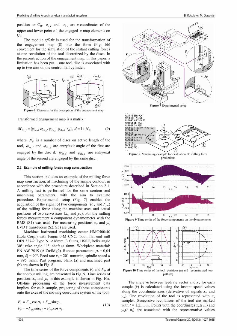
map construction, at machining of the simple contour, in accordance with the procedure described in Section 2.1. A milling test is performed for the same contour and machining parameters, with the aim to evaluate procedure. Experimental setup (Fig. 7) enables the acquisition of the signal of two components (Fxw and Fyw) of the milling force along the machine axes and actual positions of two servo axes (xw and yw). For the milling forces measurement 4 component dynamometer with the RMS (S1) was used. For measuring positions xw and yw LVDT transducers (S2, S3) are used. Machine: horizontal machining center HMC500/40 (Lola Corp.) with Fanuc 0-M CNC. Tool: flat end mill DIN 327-2 Type N, ∅16mm, 3 flutes, HSSE, helix angle 30°, rake angle 11°, shaft ∅16mm. Workpiece material: EN AW 7019 (AlZn4Mg2). Runout parameters: ρr = 0,04 mm, θr = 90°. Feed rate vf = 201 mm/min, spindle speed n = 895 1/min. Part program, blank (a) and machined part (b) are shown in Fig. 8.
The time series of the force components Fx and Fy, at the contour milling, are presented in Fig. 9. Time series of positions xw and yw in this example is shown in Fig. 10a. Off-line processing of the force measurement data implies, for each sample, projecting of these components onto the axes of the moving coordinate system of the tool:
.cossin
,sincos
fwfw
fwfw
ηη
ηη
yxx
yxx
FFF
FFF
+−=
+= (10)
Figure 7 Experimental setup
Figure 8 Machining example for evaluation of milling force
predictions
Figure 9 Time series of the force components on the dynamometer
Figure 10 Time series of the tool positions (a) and reconstructed tool
path (b)
The angle ηf between feedrate vector and xw for each sample (k) is calculated using the instant speed values along the coordinate axes (derivative of signals xw and yw). One revolution of the tool is represented with ns samples. Successive revolutions of the tool are marked with t = 1,2,..., nt. Points with the coordinates xw(t ns) and yw(t ns) are associated with the representative values
1030 Technical Gazette 20, 6(2013), 1027-1035

B. Kokotović, M. Glavonjić Predviđanje sila glodanja u virtualnom obradnom sustavu
(min/max) of the force components defined using the samples from the intervals [(t−1)ns, t ns].
The program SimPath (Fig.4) is used for predicting the representative values of the force components, for the same conditions as in experiment. Parameters of the simulation of forces at one spindle revolution are: - increment for the tool path discretization: ∆Lp =0,5
mm - increment of the z-map basis: ∆m=0,5 mm - tool discs thickness: dz =0,5 mm - angular increment of the 1 tool revolution: ∆θ =1,0°.
Cutting forces for the considered workpiece material
and material of the tool and its cutting geometry previously discussed, have been identified by the experiment and based on the mechanistic method [10]: [Ktc Krc] (N/mm2) = [1113 384,2 ], [Kte Kre] (N/mm) = [11,1 11,6 ].
Fig. 11 shows the results of the program Sim_Path,
with the predictions of the instant values of force components for simulated 1 tool revolution, in the position X-5.Y19 (block N300 of the program, Fig. 8).
Figure 11 Example of the simulation results for one point of the
discretized tool path
Figure 12 Predicted and measured representative values of milling
force components (upper and lower envelope)
In Fig. 11 is also included the updated model of the workpiece in the current position, as well as the reconstructed engagement map using described modules – explorer and zfi2fiz.
For constructing the milling force map min. and max. values of force components are used, obtained from the profile of their instant values (simulated one tool revolution) in each point of the discretized tool path.
Assuming the constant velocity along the tool path, it is possible to present predicted representative values of the milling force components as the functions of time. In that way it is possible to form comparative graph of the predicted (F∗,p) and measured (F∗,m) representative values along time axis (Fig. 12).
Figure 13 Predicted and measured representative values
of Fy force along the tool path
Fig. 13 shows the example of the force map with the distribution of representative values (lower envelope) of Fxy force along the tool path: predicted (Fxy,max,p) and (Fxy,max,m) obtained from experiment. 3 Predicting of milling forces in final machining of 2D
contours with the constant depth
Achieving of specified accuracy of the machined contours implies final machining operations with the uniform stock formed during the previous pass of the same or different tool. Depending on the shape of the contour, stock amount, radius of the tool used in the previous operation and radius of the tool for the finishing of the contour, the engagement map will be variable along the tool path. This issue has been described in literature, and some procedures for the prediction of force for finishing of rectangular pockets have been discussed [11].
Figure 14 Illustration of typical modes at final milling
of the planar contour with constant depth
Tehnički vjesnik 20, 6(2013), 1027-1035 1031
Predicting of milling forces in a virtual manufacturing system B. Kokotović, M. Glavonjić
This paper includes a more systematic approach. Fig. 14 shows various modes at the final milling of a particular contour. Generally, it is possible to define the following regimes (Fig. 14c), at final milling of planar contours: NW Zero width of cut, at start/end phases of the milling
of contour TW Variable immersion (engagement) angle in entry
and exit phase of the mill into/from the workpiece material
SL Machining along linear segment of the path with the width of the cut equal to the remaining radial stock (nominal stationary conditions)
SA Milling with circular interpolation. The width of cut is a result of the remaining radial stock, radius of the contour and the radius of the tool for the final pass (pseudo-nominal steady conditions)
TE Transition mode at the end of the path element, described with one block of the NC program
TS Transition mode at the start of the path element, described with one block of the NC program.
Prediction of milling forces along the programmed
path, at final machining of contours with the flat end mill, with the constant depth is based on several premises: • Reconstruction of the engagement map at points of
discretized path is achievable from the description of the path (NC program) and constant parameters: the depth of cut a, tool radius Rt for final pass, radial stock value δ, used in programming of the previous milling pass, the radius of the tool Rtp, used in the previous milling pass of the contour and the parameter which defines the side (left/right) of the machining.
• The reconstruction of the engaged map along the programmed path implies the procedure which is performed in steps. Each step performs the analysis of the actual program block (an element of the tool path) and the following one.
• Predictions of the representative values of the milling force components are performed based on the reconstructed engagement map and the profile of the instant values, obtained by the simulation of one revolution of the tool (module Sim1Rev, Section 2.1)
The procedure for milling forces predicting, as presented in this section, is limited to the programming of the tool path in the mode G40 (without compensation of tool radius). Processing in one step includes: • Calculation of entry/exit angle (ϕs, ϕe) at the starting
segment of block Bj, according to the initial conditions transferred from the previous step of the procedure.
• Calculation of the limits of specific intervals of block Bj based on the description of blocks Bj and Bj+1. In the points on Bj, within each interval angles ϕs and ϕe are to be calculated according to the certain function. The limits of the intervals on the path element as well as the angles are to be calculated according to the particular rule. Subprogram of the rule is to be initiated depending on the form and the spatial relation between Bj and Bj+1 elements.
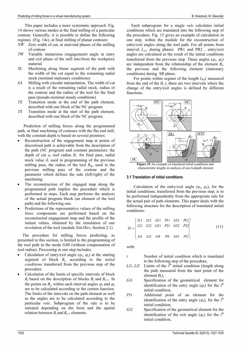
Each subprogram for a single rule calculates initial conditions which are translated into the following step of the procedure. Fig. 15 gives an example of calculation in one step, within the module for the reconstruction of entry/exit angles along the tool path. For all points from interval La1, during phases PR1 and PR2 , entry/exit angles are calculated as the result of the initial conditions transferred from the previous step. These angles (ϕs, ϕe) are independent from the relationship of the element Bj, the previous and the following element (stationary conditions) during SR phase.
For points within segmet of the length Lb1( measured from the end of the Bj ), there are two intervals where the change of the entry/exit angles is defined by different functions.
Figure 15 An example of translated initial conditions and characteristic lengths in analysis of one toolpath element
3.1 Translation of initial conditions
Calculation of the entry/exit angle (φs, φe), for the initial conditions, transferred from the previous step, is to be performed independently from the appropriate rule for the actual pair of path elements. This paper deals with the following structure for the description of translated initial conditions:
=
221121
222221212221121211111211
PtGtPtGtLtLt
PGPGLLPGPGLL
TC (11)
with: t Number of initial condition which is translated
to the following step of the procedure, Li1, Li2 Limits of the ith initial condition (length along
the path measured from the start point of the element Bj),
Gi1 Specification of the geometrical element for identification of the entry angle (ϕs) for the ith initial condition,
Pi1 Additional point of an element for the identification of the entry angle (ϕs), for the ith initial condition,
Gi2 Specification of the geometrical element for the identification of the exit angle (ϕe) for the ith
initial condition,
1032 Technical Gazette 20, 6(2013), 1027-1035

B. Kokotović, M. Glavonjić Predviđanje sila glodanja u virtualnom obradnom sustavu
Pi2 Additional point of an element for the identification of the exit angle (ϕe) for the ith initial condition.
Intersection of the milling tool projection (circle) and
the appropriate geometrical element, which is used for description of the modified volume formed by the action of the block Bj−1 is to be determined in the reconstruction of the engagement map for the given initial conditions. Since the solutions for the intersection points are often double, the additonal point should be given, which is closer to the true intersection point. Geometrical elements Gi1 and Gi2 are to be defined in one of the following three ways: • [ ]0000 C for constant value of ϕs and/or ϕe
on the segment (Li1, Li2), • [ ]22111 ytxtytxt if ϕs and/or ϕe are defined as
the intersection of the milling tool circle (Rt) and the straight line defined with the coordinates of its two points,
• [ ]02 CC Ryx if ϕs and/or ϕe are defined as the intersection of the tool circle (Rt) and the arc with the radius R and the center (xC, yC).
3.2 Rules
Calculation of the characteristic intervals on the path segment Bj and the entry/exit angle (ϕs, ϕe) in the points of that segment is to be done by the activating particular rule (subprogram). Initialization of particular rule is performed depending on the line type of Bj and Bj+1 and their spatial relationship.
The rule classification is presented in Fig.16. The change of the direction refers to the angle between the feed vector in the point of transition between segments Bj and Bj+1. The change of direction to the right means clockwise direction of rotation of that vector.
Classification from Fig. 16 implies in total 54 rules of transition between the subsequent path segments. Example of calculation of characteristic intervals on the path segment Bj and angles ϕs and ϕe, according to a single rule, is illustrated in Fig. 17.
Figure 16 Rules classification
Initial elements are coordinate pairs (x,y) of start and
end points (S, E and N) of path segments Bj and Bj+1. T is a current point of the discretized element Bj. Calculations deploy primitive functions (subroutines): • AngleLL (the angle between two vectors) • Length (the distance between two points)
• OffsLin (coordinates of the points of the offset line segment for the specific offset size and side: to the left (L)/ to the right (R), view down the feed rate vector.
• IntLinArc (coordinates of the line/arc intersection point, the closer one to the specified point).
Figure 17 Example of a single rule
3.3 Milling tests
The verification of the presented procedure for the prediction of forces at the final contour milling, with the constant depth, has been illustrated with two examples shown in Fig. 18.
Figure 18 Examples of the final contour milling with constant depth
Table 1 Specific parameters for final milling of contours P201 and 202
Contour P201 P202 Number of mill flutes 4 3 Runout parameters ρr/θr / mm/° 0,03/30 0,045/100 Spindle speed n / 1/min 895 800 Feed rate vf / mm/min 268 201 sz / mm/flute 0,075 0,084 Tool radius in prev.pass Rtp / mm 16 25 Mode Down Up
Nominal radial stock left after previous pass δ = 2 mm. Axial depth a = 6 mm. End mills: DIN 327-2 type N
Tehnički vjesnik 20, 6(2013), 1027-1035 1033

Predicting of milling forces in a virtual manufacturing system B. Kokotović, M. Glavonjić
(3 and 4 flutes) HSSE, with helix angle 30° and rake angle 11°. Worpiece: ENAW 7019 (AlZn4Mg2). Other parameters for final milling of these contours are given in Tab.1.
Parameters of the simulation of the instant values of the force components (1 tool revolution) are the same as in example in Sec. 2.2. Programmed tool path for contour P201 implies the following rules for calculation of angles ϕs/ϕe: G1/G1/CL/L, G1/G2/CT/L, G2/G1/CT/L and G1/G1/CL/L. Finishing of the contour P202 implies execution of the following rules: G1/G3/CT/R, G3/G1/CT/R, G1/G1/CR/R and G1/G1/CL/R. Calculated entry/exit angles along tool paths are shown in Fig. 19.
Figure 19 Entry/exit angle along the discretized tool paths in the final
contour milling passes a) path P201 b) path P202 Min/max values of particular force components are
obtained by the simulation of a single tool revolution in each point of the discretized path for calculated angles ϕs and ϕe. Comparative views of the representative values (lower envelope) of the component Fy (predicted (Fy,min,p) and obtained from experiment (Fy,min,m)) are given in Fig. 20.
Figure 20 Predicted and experimentally obtained representative values
of the component Fy at the final milling passes, a) path P201 b) path P202
4 Conclusion
Procedures for prediction of milling forces, in the form of force maps, presented in this paper, could be treated as one of the most important building blocks in virtual manufacturing environment. Required input data structure is slightly expanded (specific cutting forces) in comparison with the files which are generally formed during standard CAM session.
Reliability of these procedures was proven through their softvare implementation and milling tests, for class of milling operations. The first procedure (using z-map) is suitable for rough milling operations. System of rules and concept of translation of initial conditions were used in development of the second procedure, which is suitable for finishing of planar contours.
There are several reasons for greater quantitative differences between measured and predicted values in some segments of toolpaths. One of them is the fact that model of rigid bodies was used. On the other side, experimental results are influenced by additional change of uncut chip thickness caused by significant compliance of the dynamometer. Lower accuracy of predictions in Fig. 12 are partly caused by chosen resolution of z-map. Finally, in examples in Fig. 20 expected errors (start/end sections of the tool path) are caused by absence of workpiece model in reconstruction of tool contact area. 5 References [1] Ko J. H.; Yun W. S.; Cho D. W.; Ehmann K. F.
Development of a virtual machining system, part 1: Approximation of the size effect for cutting force prediction // Int. J. of Machine Tools & Manufacture. 42, 1(2002), pp. 595-605.
[2] Altintas Y.; Brecher C.; Weck M.; Witt S. Virtual Machine Tool, Keynote Paper of STC M // Annals of CIRP. 54, 2(2005), pp. 651-674.
[3] Li, J. G.; Zhao, H.; Yao, Y. X.; Liu, C. Q. Off-line optimization on NC machining based on virtual machining // Int. J. Adv Manuf. Technol. 36, (2008), pp. 908-917.
[4] Mandić V. et al. Concurrent engineering based on virtual manufacturing. // Tehnicki vjesnik-Technical Gazette. 19, 4(2012), pp. 885-892.
[5] World Modeling, Value Judgment and Knowledge Representation. // Engineering of Mind / Albus J. S.; Meystel A. M.: John Wiley and Sons, 2001, pp. 195-242.
[6] Lee, U. H.; Cho, D. W. An intelligent feedrate scheduling based on virtual machining. // Int. J. Adv. Manuf. Technol. 22, (2003), pp. 873-882.
[7] Mechanics of Metal Cutting // Manufacturing Automation / Altintas Y.: Cambridge University Press, 2000, pp. 4-64.
[8] Armarego, E. J. A.; Despande, N. P. Computerized predictive cutting model for cutting forces in end-milling including eccentricity effects. // Annals of CIRP. 38, (1989), pp. 45-49.
[9] Jang, J. Z.; Wang, Q. F.; Hung, Z. D.; Chen, G. Cutting area extraction from a Z-map model. // Int. J. Adv. Manuf. Technol. 33, (2007), pp. 1010-1016.
[10] Budak, E.; Altintas, Y.; Armarego, E. J. A. Prediction of Milling Force Coefficients From Orthogonal Cutting Data. // Journal of Manufacturing Science and Engineering, Trans. of the ASME. 118, (1996), pp. 216-224.
[11] Bae, S. H.; Ko, K.; Kim, B. H.; Choi, B. K. Automatic feedrate adjustment for pocket machining. // Computer-Aided Design. 35, (2003), pp. 495-500.
1034 Technical Gazette 20, 6(2013), 1027-1035

B. Kokotović, M. Glavonjić Predviđanje sila glodanja u virtualnom obradnom sustavu
Authors' addresses Branko Kokotović, M.Sc.(ME) University of Belgrade Faculty of Mechanical Engineering Kraljice Marije 16 11120 Beograd 35 Republic of Serbia [email protected] Miloš Glavonjić, Ph.D., Full.Prof. University of Belgrade Faculty of Mechanical Engineering Kraljice Marije 16 11120 Beograd 35 Republic of Serbia [email protected]
Tehnički vjesnik 20, 6(2013), 1027-1035 1035