Embed Size (px)
Citation preview
` Proceedings of the 1st International and 16th National Conference on Machines and Mechanisms (iNaCoMM2013), IIT Roorkee, India, Dec 18-20 2013
Predicting the Dynamic Behaviour of Hybrid Stepper Motor
Aayush Kejriwal[1], Shamrao[1], N. Viswanatha[2] [1] Engineer, [2] Group Director, Spacecraft Mechanism Group
ISRO Satellite Centre, HAL Airport Road, Bangalore-560017, India
Email: [email protected]
Abstract— Stepper motors drives with their simple position control and drive electronics are the most preferred alternative to the traditional spring based deployment systems of large spacecraft appendages. However for the proper use of the motor, there is need to understand and simulate its complex dynamic behavior in driving large inertia loads. The dynamic simulation model has to be developed with the limited data available in the data sheets of the motor. The validity of the motor constant supplied in the data sheet is verified by measuring the peak torque developed for different phase current. The damping coefficient (not provided in data sheet) needed for the dynamic model has been estimated using the simulation in comparison with the experimental single step response. The simulation model developed effectively predicts the multistep response of the stepper motors with large inertia. The model has been successfully validated against experimental data. The simulation paper also aims at improving the understanding of stepper motor for future use in deployment mechanism. An experimental test set up is realized for validating the simulation results.
Keywords— Hybrid stepper motor, electromechanical model, dynamic behaviour.
I. INTRODUCTION
The spacecraft generally have many appendages viz., solar arrays, reflectors and payload instruments which need to be stowed during launch to meet the envelope constraints, and to provide support during launch and deployed on orbit. Generally the appendages are deployed using the traditional spring energy based hinge mechanism and locked in the required orientation. In recent times the spacecraft missions have gone complex necessitating large appendages to meet the mission requirements. The traditional spring based system need large torque and as a consequence needs a bigger damper to reduce latch up moments at the end of deployment on the hinge mechanism and on the appendages. Hence, the use of motors as primary drive has become inevitable to meet the stringent mass budgets for the deployment mechanism.
There are several types of motor to choose from for space applications such as Brush DC (BDC) motor, Brushless DC (BLDC) motor, synchronous motor, stepper motor etc. BDC motors do not provide the redundancy and reliability needed for high reliable deployment mechanisms. The BLDC and stepper motors can be constructed with redundant coils for electrical redundancy
and do not have parts that wear out with use, hence providing edge over the BDC motors. BLDC motor requires sensor (additional hardware) for its operation and the feedback drive electronics construction is complex. Whereas, Stepper motor due to its inherent construction allows the commutation of motor windings to be done completely electronically without feedback sensors [1]-[2]. This property allows the stepper motor to be chosen as a simple, cheap and reliable motion device.
Stepper motors in spite of being a simple device for motion control applications exhibit a complex dynamic behavior which needs to be understood for its proper usage. The stepper motor manufacturers use a thumb rule that the motor to be used for driving an inertia which is approximately 5 times the rotor inertia. This is a general guideline for positioning application where the payload has to be parked to the required position with high reliability to avoid overshooting. However, the use of stepper motor for deploying a large inertia appendage requires this aspect to be closely looked at from dynamics point. Hence, to ascertain that the motor is able to deploy the appendage a prior to the selection of the motor, there is a need to simulate the same. Taking this into account this paper explores the possibility of predicting the dynamic behavior of stepper motor with load inertia using a MATLAB code and verifying the same against experiment investigation.
II. MATHEMATICAL MODELLING
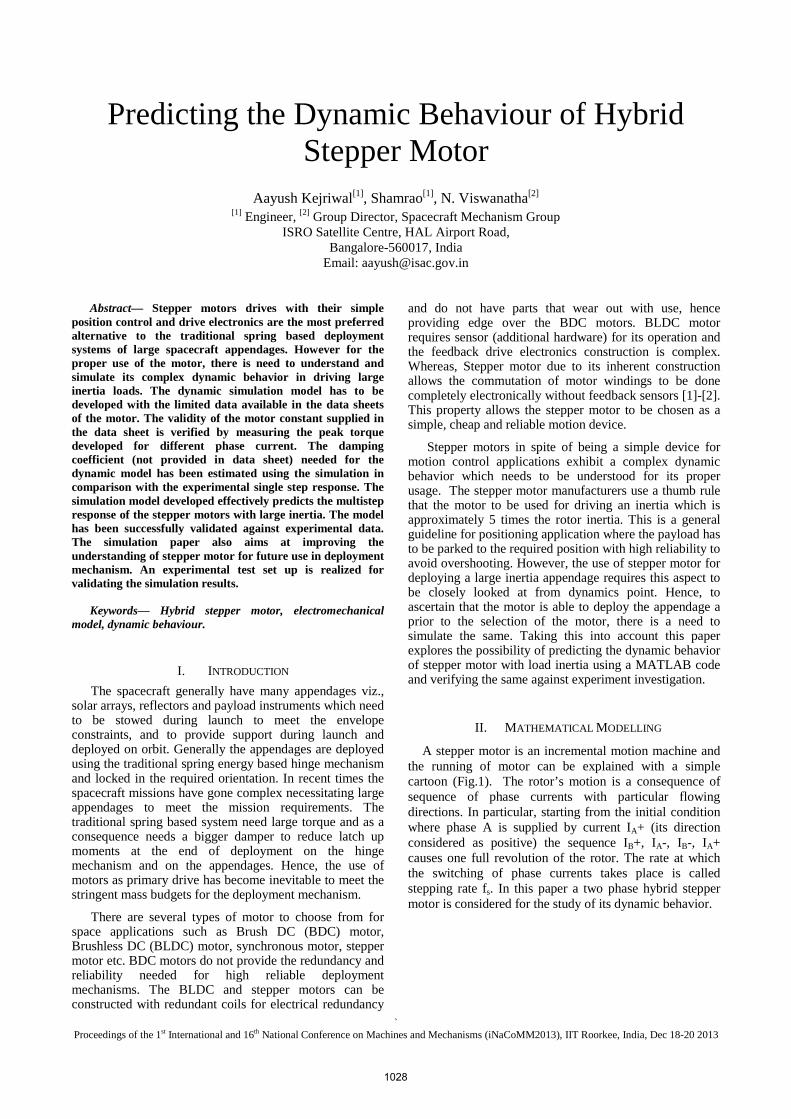
A stepper motor is an incremental motion machine and the running of motor can be explained with a simple cartoon (Fig.1). The rotor’s motion is a consequence of sequence of phase currents with particular flowing directions. In particular, starting from the initial condition where phase A is supplied by current IA+ (its direction considered as positive) the sequence IB+, IA-, IB-, IA+ causes one full revolution of the rotor. The rate at which the switching of phase currents takes place is called stepping rate fs. In this paper a two phase hybrid stepper motor is considered for the study of its dynamic behavior.
1028
` Proceedings of the 1st International and 16th National Conference on Machines and Mechanisms (iNaCoMM2013), IIT Roorkee, India, Dec 18-20 2013
Fig. 1 Sketch of the running principle of a step motor [3].
A. Dynamic Model
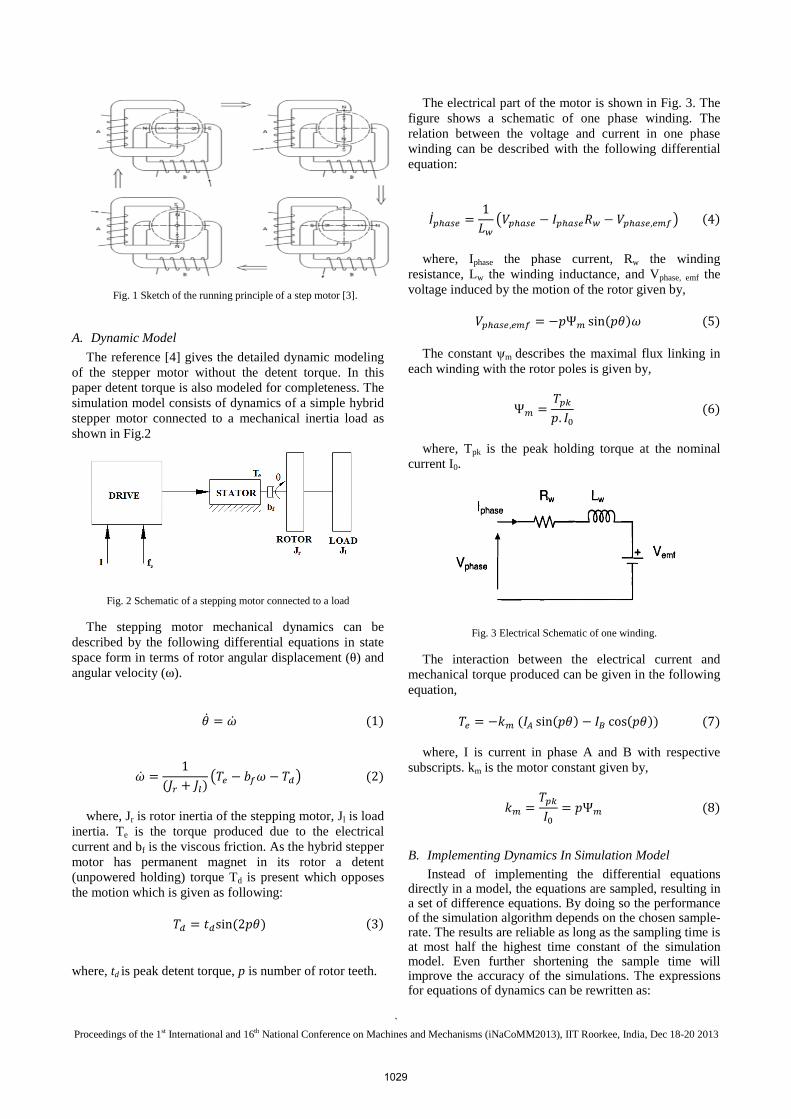
The reference [4] gives the detailed dynamic modeling of the stepper motor without the detent torque. In this paper detent torque is also modeled for completeness. The simulation model consists of dynamics of a simple hybrid stepper motor connected to a mechanical inertia load as shown in Fig.2
Fig. 2 Schematic of a stepping motor connected to a load
The stepping motor mechanical dynamics can be described by the following differential equations in state space form in terms of rotor angular displacement (θ) and angular velocity (ω).
1
1
2
where, Jr is rotor inertia of the stepping motor, Jl is load inertia. Te is the torque produced due to the electrical current and bf is the viscous friction. As the hybrid stepper motor has permanent magnet in its rotor a detent (unpowered holding) torque Td is present which opposes the motion which is given as following:
sin23
where, td is peak detent torque, p is number of rotor teeth.
The electrical part of the motor is shown in Fig. 3. The figure shows a schematic of one phase winding. The relation between the voltage and current in one phase winding can be described with the following differential equation:
1
,4
where, Iphase the phase current, Rw the winding resistance, Lw the winding inductance, and Vphase, emf the voltage induced by the motion of the rotor given by,
, Ѱ sin 5
The constant ψm describes the maximal flux linking in each winding with the rotor poles is given by,
Ѱ .
6
where, Tpk is the peak holding torque at the nominal current I0.
Fig. 3 Electrical Schematic of one winding.
The interaction between the electrical current and mechanical torque produced can be given in the following equation,
sin cos 7
where, I is current in phase A and B with respective subscripts. km is the motor constant given by,
Ѱ8
B. Implementing Dynamics In Simulation Model
Instead of implementing the differential equations directly in a model, the equations are sampled, resulting in a set of difference equations. By doing so the performance of the simulation algorithm depends on the chosen sample-rate. The results are reliable as long as the sampling time is at most half the highest time constant of the simulation model. Even further shortening the sample time will improve the accuracy of the simulations. The expressions for equations of dynamics can be rewritten as:
1029
` Proceedings of the 1st International and 16th National Conference on Machines and Mechanisms (iNaCoMM2013), IIT Roorkee, India, Dec 18-20 2013
% 1& % &'
% &9
1
(10)
with k as the sample index, and N the amount of samples per second.
% & % & sin% & % & cos% &11
The current through the windings is,
1 1
,
12
1 1
,
13
The emf produced by the rotation of the rotor is,
,% & sin% &% & 14 ,% & cos% &% & 15
III. MOTOR SPECIFICATIONS
The motor used for the experiment is of Phytron make with following specifications:
TABLE I. DATA SHEET
Peak Holding Torque (Tpk) (2 phases on) 0.077 Nm Rotor Inertia (Jr) 1.1x10⁻⁶ kg-m2 Winding Resistance(R) 36 Ω Winding Inductance(L) 0.04 H Rated Current(I0) 0.3 A Step Size 1.8° No. of Rotor teeth (p) 50 Peak Detent Torque (td) 0.003
TABLE II. DERIVED FROM DATA SHEET
Motor Constant (km) 0.18166 Nm/A Max. Flux linkage (Ѱm) 0.00363V/s
IV. TEST SET UP
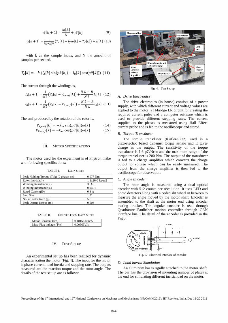
An experimental set up has been realized for dynamic characterization the motor (Fig. 4). The input for the motor is phase current, load inertia and stepping rate. The outputs measured are the reaction torque and the rotor angle. The details of the test set up are as follows:
Fig. 4. Test Set up
A. Drive Electronics
The drive electronics (in house) consists of a power supply, with which different current and voltage values are applied to the motor, a H-bridge LR circuit for creating the required current pulse and a computer software which is used to provide different stepping rates. The current supplied to the phases is measured using Hall Effect current probe and is fed to the oscilloscope and stored.
B. Torque Transducer
The torque transducer (Kistler-9272) used is a piezoelectric based dynamic torque sensor and it gives charge as the output. The sensitivity of the torque transducer is 1.6 pC/Ncm and the maximum range of the torque transducer is 200 Nm. The output of the transducer is fed to a charge amplifier which converts the charge output to voltage which can be easily measured. The output from the charge amplifier is then fed to the oscilloscope for observation.
C. Angle Encoder
The rotor angle is measured using a dual optical encoder with 512 counts per revolution. It uses LED and photo detectors along with a coded slit wheel in between to measure the angle moved by the motor shaft. Encoder is assembled to the shaft at the motor end using encoder mating bracket. The angular encoder is read through Quadrature Faulhaber motion controller through CAN interface bus. The detail of the encoder is provided in the Fig.5.
Fig. 5. Electrical interface of encoder
D. Load inertia Simulation
An aluminum bar is rigidly attached to the motor shaft. The bar has the provision of mounting number of plates at the end for simulating different inertia load on the motor.
1030

` Proceedings of the 1st International and 16th National Conference on Machines and Mechanisms (iNaCoMM2013), IIT Roorkee, India, Dec 18-20 2013
V. RESULTS AND DISCUSSIONS
A. Torque versus phase current
The motor was run with different phase currents for single step response and peak torque is noted from the torque transducer output. The plot (Fig. 6) of the peak torque against phase current shows that the linearity is maintained for the current below the rated current of motor, after which the magnetic saturation limits the torque developed in the motor. This indicates that motor constant km has to be changed accordingly in the simulation model.
Fig. 6. Peak Torque v/s Phase Current
B. Determination of damping coefficient
The motor manufacturer data is inadequate for the dynamic modeling of the motor. The damping information is not provided in the specifications sheet. Viscous damping coefficient has to be found from experiment for complete dynamic modeling of the stepper motor. Single step response method is used to estimate the damping coefficient. Since motor is used to drive load, the damping coefficient is estimated for different load inertia as the loading method induces reaction force which in turn creates frictional torque on the motor bearing. The estimated damping coefficient is used for simulating multistep response of the motor.
Rotor Inertia Only: The single step response was measured for the rated current. The Fig. 7 shows plots of the torque produced by the motor and the angular position of the rotor with time. The damping coefficient bf is found out by trial and error method using the code. The Fig. 8 shows the resulting fit for numerical simulation with estimated viscous damping coefficient against the experimental torque and angular position measurement. The viscous damping coefficient (bf) estimated from the simulation is 0.00015 Nm-sec/rad.
Fig. 7. Measured Single Step Response
Fig. 8. Simulation step response calibrated against measurement
Rotor and Load Inertia: The single step response was measured for the rated phase current with two different load inertias of approximately 800 and 2000 times the rotor inertia. Fig. 9 shows the resulting fit for numerical simulation with estimated viscous damping coefficient against the experimental angular position measurement with load inertia. The viscous damping coefficient bf estimated from simulation is given in Table III.
(a) 0.3 A and 0.8x10⁻³ kg-m2
(b) 0.3 A and 2x10⁻³ kg-m2
Fig. 9. Single step response with load inertia.
TABLE III. VISCOUS DAMPING COEFFICIENTS
Sl. No.
Phase Current (A)
Load Inertia (kg-m2)
Viscous Damping Coefficient
1 0.3 0.8x10⁻³ 0.0021 2 2x10⁻³ 0.003
C. Multi step response
The motor without load inertia was run at a stepping rate of 41.6 Hz. The Fig. 10 shows the comparison of angular position measured against the updated dynamic
1031

` Proceedings of the 1st International and 16th National Conference on Machines and Mechanisms (iNaCoMM2013), IIT Roorkee, India, Dec 18-20 2013
simulation model. The simulation closely predicts the multistep behaviour of the stepper motor.
Fig. 10. Multistep response of motor without load inertia (fs = 41.6 Hz)
Similarly the motor was run with load inertia of 0.8x10⁻³ kg-m2 which is approximately 800 times the rotor inertia. Fig. 11 shows the measured angular position with the simulated result. The experiment confirms that the motor is able to drive large load inertia for the given number of steps which is captured by the simulation as well.
Fig. 11. Multistep response of the motor with load inertia (fs = 41.6 Hz)
VI. CONCLUSIONS
The hybrid stepper motor dynamic model has been simulated in MATLAB using difference equation. The applicability of the motor constant given in the data sheet for different phase currents is verified with experimental observations. It is found that the data sheet motor constant is applicable for the phase currents below the rated current of the motor. The motor magnet circuit reaches its saturation with increased phase current beyond rated current. The viscous damping coefficient required for the dynamic model is estimated from the simulation code by comparison with the experimental data with and without load inertia. The damping coefficient is used for simulating multistep response of the motor. The simulation model closely predicts the multistep response of the motor with and without load inertia. It is observed that the motor is able to deploy a large load inertia compared to its rotor inertia. This finding clearly indicates that the stepper motor can reliably be used to drive large load inertia. The simulation model is successfully validated with experimental test results. The dynamic model simulation can be used for selection of stepper motor for deployment mechanisms.
REFERENCES [1] Paul Arcanley, “Stepping motors: a guide to theory and practice”,
4th edition, The Institution of Electrical Engineers, 2007.
[2] Kenjo, T., “Stepping Motors and Their Microprocessor Controls”, Clarendon Press, Oxford, 1985.
[3] Paolo Righettini, et.al. , “An Experimental Investigation on the Dynamic Behaviour of Step Motor Drives”, Journal of Mechanics Engineering and Automation 2 (2012) 431-440.
[4] Vierbergen, R. O., “Predicting and improving the behaviour of stepping motors”, Master of Science Thesis, Eindhoven University of Technology, and Dept. Of Electrical Engineering, 2005.
1032