Embed Size (px)
Citation preview
ARTICLE IN PRESS
Composite Structures xxx (2005) xxx–xxx
www.elsevier.com/locate/compstruct
Flexural behaviour of GFRP–concrete hybrid beamswith interconnection slip
Joao R. Correia *, Fernando A. Branco 1, Joao G. Ferreira 2
Department of Civil Engineering and Architecture, Instituto Superior Tecnico, Technical University of Lisbon,
Av. Rovisco Pais 1049-001, Portugal
Abstract
The design of glass fibre reinforced polymer (GFRP) pultruded beams is usually governed by deformability or instability phe-nomena. To obtain a better use of the material properties, the GFRP profiles can be connected to concrete elements with severaladvantages, associated with the global stiffness and strength of the structural elements. This leads to solutions particularly usefulfor rehabilitation of old floors or even new construction slabs. This paper presents the results of an experimental research developedto characterize the flexural behaviour of a GFRP–concrete hybrid solution. Shear connection tests were first performed on GFRP I-profiles, connected to concrete with stainless steel bolts, to evaluate the behaviour of the shear connection. The results of those testswere then used to design simply supported GFRP–concrete hybrid beams that were tested under bending conditions. The flexuralbehaviour of the GFRP–concrete hybrid beams is discussed, with particular relevance to the effect of the interconnection slip. Theoverall behaviour of the hybrid beams is compared with that corresponding to a simple GFRP I-profile beam, demonstrating thestructural advantages of this new hybrid constructive solution.� 2005 Elsevier Ltd. All rights reserved.
Keywords: Glass fibre reinforced plastics; Concrete; Shear connection; Hybrid beams; Flexural behaviour; Interconnection slip
1. Introduction
Glass fibre reinforced polymer (GFRP) pultrudedprofiles have great potential as construction materials,presenting several advantages when compared with tra-ditional materials, related to the higher strength toweight ratio, the lower self-weight, the electromagnetictransparency, the possibility of being produced withany cross-section geometry, the easier installation, thelower maintenance requirements and the improveddurability under aggressive environments [1,2].
0263-8223/$ - see front matter � 2005 Elsevier Ltd. All rights reserved.doi:10.1016/j.compstruct.2005.06.003
* Corresponding author. Tel.: +351 218 418 249; fax: +351 218 488481.
E-mail addresses: [email protected] (J.R. Correia), [email protected] (F.A. Branco), [email protected] (J.G. Ferreira).
1 Tel.: +351 218 418 230; fax: +351 218 488 481.2 Tel.: +351 218 418 213; fax: +351 218 488 481.
However, low elastic modulus leads to structuraldesigns that are usually governed by instability phenom-ena and deformability, rather than by strength limi-tations [3,4]. Moreover, the low elasticity to shear moduliratio may also result in a significant contribution of shearto the total deformation, especially in less slender beams[4,5]. These aspects, and the associated limited use of thematerial�s ultimate strength, as well as the high costs ofthese elements may explain the fact that the use ofFRP materials in new structures is still limited to a fewdemonstration projects.
The alternative use of GFRP pultruded profiles inGFRP–concrete hybrid structural elements presentshowever a very interesting potential, either for rehabili-tation (particularly in the substitution of existing oldwooden floors), or for new constructions. In fact, thereare several structural advantages with the connectionof GFRP pultruded profiles to concrete compression
Nomenclature
Ac area of the concrete layerAf area of the GFRP profile�s flangeAp area of the GFRP profileAw area of the GFRP profile�s webEc concrete�s Young�s modulusEp GFRP profile�s longitudinal flexural Young�s
modulusFc maximum compressive load in the concrete
slabFs,max maximum shear connection load obtained in
the shear connection testGp GFRP profile�s shear modulusH total height of the hybrid sectionIc inertia of the concrete layer in the major prin-
cipal axisIGFRP
eq section�s equivalent inertia homogenized inGFRP
Ip inertia of the GFRP profile in the major prin-cipal axis
K shear connection stiffnessL beam�s spanMu ultimate bending momentP value of the point loadX,el neutral axis� depth (elastic analysis)X,u neutral axis� depth (at failure)Z neutral axis� height
b width of the GFRP profile�s flangesbc width of the concrete layerbeff concrete slab�s effective widthbL longitudinal position of the point loadb0 shear connectors� transversal spacingfc concrete�s compressive strengthfsu reinforcing steel bars ultimate stressn homogenization factortf thickness of the GFRP profile�s flangestw thickness of the GFRP profile�s webh height of the GFRP profilehc thickness of the concrete layerr distance between centroids of concrete and
profile componentssc longitudinal spacing between sections with
shear connectorsx beam�s longitudinal coordinateaL adimensional stiffness of the shear connec-
tionb shear connection stiffness parameterdf midspan deflection for full shear interactiondp midspan deflection for partial shear interac-
tionecu concrete�s ultimate compressive straineslip slip strain on the interfacel average shear connection flexibility
2 J.R. Correia et al. / Composite Structures xxx (2005) xxx–xxx
ARTICLE IN PRESS
elements, namely the increase of the flexural stiffness,reducing the structure�s deformability, and the increaseof the structure�s strength capacity, making a betteruse of the GFRP profiles and preventing the bucklingphenomena.
Initial experiments with GFRP–concrete elementswere developed in rehabilitation solutions [6–8] andproved that the bonding of GFRP laminates was an effi-cient method for the strengthening of reinforced con-crete structural elements. Compared with the use ofsteel plates, this solution presents several advantages,such as the ease of application, the lower self-weightand the resistance to corrosive environments. Regardingto the rehabilitation use of carbon fibre reinforced poly-mer (CFRP) bonding systems, although the GFRP solu-tion is much less stiff, it has the advantages of its lowercost.
GFRP–concrete hybrid elements have also beendeveloped for new structural systems, combining thedirectional behaviour, the lightness and the highmechanical performance of GFRP pultruded profileswith the concrete�s compressive strength. The use of con-crete-filled fibre reinforced (FRP) tubes has been used inpiles for maritime structures [9] where it is very effective
in these aggressive environments, allowing for theexploitation of the specific advantages of each constitut-ing material. While concrete resists compression andprevents the failure of the tube due to instability phe-nomena, the FRP element confines the concrete, con-tributing to a strength and ductility increase, andprotection from aggressive environment. Additionally,the tube acts as formwork, allowing for higher construc-tion speed rates. Fam and Rizkalla [10] and Fam et al.[11] tested the use of this solution in beams and columns,respectively. Deskovic et al. [12] and Ribeiro et al. [13]studied the viability of using other type of hybrid beamsbuilt by thin walled FRP elements bonded to concrete orpolymeric concrete compression elements, respectively.Seible et al. [14] developed two hybrid systems with dif-ferent shear connection devices to be used in structuralelements of bridge decks. In the Concrete filled carbon
shell system, which is suitable for both columns andgirders, the connection between the deck and the carbonshell girders is achieved with conventional dowel tech-nology by embedding shear connectors into the shellsystem during grouting. In the Hybrid tube bridge sys-
tem, an FRP form panel is snap-locked to the top ofFRP hollow girders, functioning as a tension tie between
J.R. Correia et al. / Composite Structures xxx (2005) xxx–xxx 3
ARTICLE IN PRESS
girders and the stay in place form for a polypropylenefibre reinforced arch-action type concrete deck.
This paper presents the results of an experimental re-search concerning the flexural behaviour of a newGFRP–concrete hybrid solution. Shear connection testswere first performed on GFRP I-profiles, made of E-glass fibres and polyester resin, connected to concretewith stainless steel bolts. The results of those shear testswere then used to design simply supported GFRP–con-crete hybrid beams that were experimentally tested inbending. The flexural behaviour of the hybrid beams isdiscussed, regarding both service and ultimate behav-iour, with particular relevance to the effect of the inter-connection slip. The overall behaviour of the hybridbeams is compared with that of a simple GFRP I-pro-file, demonstrating the technical advantages of thisnew constructive solution.
2. Analysis of GFRP–concrete hybrid beams
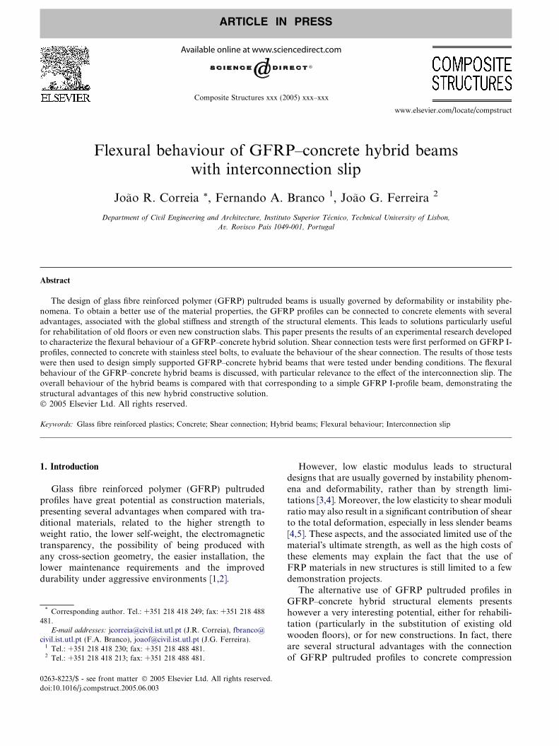
A typical cross-section for a GFRP–concrete hybridbeam is shown in Fig. 1, with the corresponding dimen-sions, together with the strain and stress distributionscorresponding to elastic and failure analysis. The GFRPprofile has an area Ap, principal inertia Ip (horizontalaxis), web area Aw and a flange area Af; the concretelayer has an area Ac and principal inertia Ic (horizontalaxis). The properties of the materials are: Ec = Young�smodulus of concrete; fc = compressive strength of con-crete; ecu = ultimate compressive strain of concrete;Ep = profile�s longitudinal flexural Young�s modulus;Gp = profile�s shear modulus.
2.1. Serviceability analysis
2.1.1. Elastic analysis with complete shear interaction
The elastic analysis of the GFRP–concrete hybridsection (Fig. 1(a1)) can be performed assuming the fol-lowing classical hypotheses:
(a) Elastic a
εsl
(ain
X,el
(a1) Completeinteraction
εεc
X,el
Z
Fig. 1. Cross-section dimensions and longit
• Bernoulli�s hypothesis is valid.• The whole width of the concrete slab is effective.• There is complete shear interaction between the con-
crete slab and the GFRP profile, i.e., there is no lon-gitudinal slippage between the materials.
• There is no vertical separation between the concreteslab and the GFRP profile.
Those hypotheses lead to the following bending equa-tions for the depth of the neutral axis (X,el) and the sec-tion�s equivalent inertia ðIGFRP
eq Þ, being n = Ec/Ep:
(a) considering concrete�s tensile strength (valid onlybefore cracking occurs),� �
nalysis
ip
2) Partialteraction
ε
udinal
X ;el ¼Ap � hc þ h
2þ n� Ac � hc
2
Ap þ n� Ac
ð1Þ
IGFRPeq ¼ n� Ac � h2
c
12þ n� Ac � X ;el �
hc
2
� �2
þ Ip þ Ap � hc þh2� X ;el
� �2
ð2Þ
(b) not considering concrete�s tensile strength (validafter cracking occurs), � �
n� bc � X 2;el þ 2 � Ap � X ;el � 2 � Ap � hc þh2
¼ 0 ð3Þ
IGFRPeq ¼
n� bc � X 3;el
3þ Ip þ Ap � hc þ
h2� X ;el
� �2
ð4Þ
2.1.2. Elastic analysis with partial shear interaction
When the flexibility of the shear connection is consid-ered, a slip strain (eslip) occurs on the interface betweenthe two materials of the hybrid beam (Fig. 1(a2)), corre-sponding to the difference between concrete and GFRPstrains at the interface. Therefore, a reduction of the
σp
(b) Failure analysis
(b1) Fullconnection
εc = 0,0035
X,u
(b2) Partialconnection
εc = 0,0035
ε
X,u
εslip
ε
0.8 Xe,u
σσc = fc
(b3) Stressdistribution
strain and stress distributions.
4 J.R. Correia et al. / Composite Structures xxx (2005) xxx–xxx
ARTICLE IN PRESS
flexural stiffness occurs, and its magnitude depends onthe connection�s flexibility. In the limit, when there isno shear interaction, the profile and the concrete layerwork separately and the hybrid beam�s stiffness corre-sponds to the sum of the stiffnesses of each isolatedelement.
Knowles [15] presented analytical solutions to deter-mine the slip strain throughout the span of simply sup-ported hybrid beams under several load cases andassuming the following hypotheses:
• Discrete shear connection can be replaced by anequivalent uniform continuous linearly elasticmedium.
• The curvature and vertical deflection of bothcomponents are the same.
• The beams� behaviour is linear elastic.• Bernoulli�s hypothesis is applicable to both
materials separately.
For a simply supported beam with span L, submittedto a point load P applied at a distance bL from one ofthe end supports, the slip strain eslip can be determined(at a coordinate x, measured from the same end sup-port) using the following equation:
eslipðxÞ ¼ l �Ap � h
2þ hc � X ;el
� �IGFRP
eq
� P
� B� sinhðB� bLÞ � sinhðB� xÞsinhðB� LÞ ð5Þ
where
B ¼
ffiffiffiffiffiffiffiffiffiffiffiffiffiffiffiffiffiffiffiffiffiffiffiffiffiffiffiffiffiffiffiEI
l �P
EI � EA
sEA ¼ Ec � Ac � Ep � Ap
Ec � Ac þ Ep � ApXEI ¼ Ec � I c þ Ep � Ip EI ¼
XEI þ EA� r
where r is the distance between centroids of concrete andprofile, and l is the average shear connection flexibility,determined by the ratio between the beam�s span and thetotal shear connection stiffness (product of each connec-tor shear stiffness by the total number of connectors).
Girhammar and Gopu [16] presented a solution forthe ratio between the midspan deflection (due to bend-ing) in simply supported beams submitted to an uni-formly distributed load with full shear interaction (df)and partial shear interaction (dp),
dp
df
¼ 1 þEIGFRP
eq
EcI c þ EpIp
� 1
!� b ð6Þ
where the parameter b depends on the adimensionalstiffness of the shear connection aL (b = 0 for full shearinteraction and b = 1 for no shear interaction),
b ¼ 1
cosh aL2
� �þ 1
8ðaLÞ2 � 1
" #� 384
5ðaLÞ4ð7Þ
a2 ¼ 1
l� 1
EpAp
þ 1
EcAc
þ r2
EpIp þ EcIc
� �ð8Þ
According to a numerical study by Wang [17], the errorof using Eq. (6) for different load arrangements and sup-porting conditions is very small. For simply supportedbeams submitted to a point load at midspan the erroris only 2% (comparing with the uniformly distributedload case).
2.1.3. Deflection
The global deformation of GFRP–concrete hybridbeams results from the sum of the deflection due tobending, considering the connection flexibility, and thedeflection due to shear. A shear load acting on the beamis distributed between the concrete slab and the GFRPprofile, but here the shear deformation is significant. Aconservative hypothesis is then assumed, consideringthat shear is carried only by the profile�s web. Under thishypothesis, the maximum deflection of simply supportedGFRP–concrete hybrid beams, submitted to a pointload P applied at any point along its span, can be com-puted by
d ¼ P � L3
K1 � EIGFRPeq
� dp
df
� �þ P � LK2 � Gp � Aw
ð9Þ
where K1 and K2 are factors which depend on the load�sposition and are given by elasticity theory (for a load ap-plied at midspan, K1 = 48 and K2 = 4).
2.2. Ultimate strength
2.2.1. Failure analysis with full shear connection
The hybrid beam loaded in bending can fail in severalways, namely due to bottom flange tension (flexural)failure; web shear failure (fracture or buckling); webcompressive local buckling; concrete shear failure; con-crete compressive failure; lateral bucking global failure;and interface shear connection failure.
The present study of hybrid beams took into consid-eration those possible failure scenarios and the beamdimensions were chosen so that failure occurs with com-pression in concrete, and with the neutral axis lying onthe concrete slab. The first condition is set because,among the possible failure scenarios, concrete compres-sive failure is the most ductile mechanism, providing apseudo-ductile behaviour. The second condition aims ata better use of the profile�s mechanical properties.
In simply supported hybrid beams, with concretecompressive failure, the longitudinal spacing betweenshear connectors sc, to provide full shear connection,can be estimated by

J.R. Correia et al. / Composite Structures xxx (2005) xxx–xxx 5
ARTICLE IN PRESS
sc ¼F s;max
F c
L=2
� � ð10Þ
where Fs,max is the maximum shear connection load (ob-tained in the shear connection test) and Fc is the maxi-mum compressive load in the concrete slab,
F c ¼ 0.8 � X ;u � bc � fc ð11Þwith X,u = neutral axis depth at failure.
The failure analysis of a GFRP–concrete hybrid sec-tion (Fig. 1(b1)), assuming complete shear connection(i.e., spacing between shear connectors provides themaximum bending strength), leads to the following neu-tral axis depth (X,u) and to the ultimate bending moment(Mu), considering ec = ecu = 0.0035,
ð0.8 � bc � fcÞ � X 2;u þ ðAp � Ep � ecÞ � X ;u
� Ap � Ep � ec �h2þ hc
� �¼ 0 ð12Þ
Mu ¼ ð0.8 � bc � X ;u � fcÞ � ð0.6 � X ;uÞ þ ðAf � EpÞ
� ec
X ;u
� tf2þ hc � X ;u
�� �� H � X ;u � hþ tf
2
�
þ ðAw � EpÞ �ec
X ;u
� h2þ hc � X ;u
� �� �
� H � X ;u �h2
� �þ ðAf � EpÞ
� ec
X ;u
� h� tf2þ hc � X ;u
�� �H � X ;u �
tf2
�ð13Þ
where the stresses in the concrete slab are calculatedbased on the equivalent rectangular stress block ap-proach (Fig. 1(b3)).
2.2.2. Failure analysis with partial shear connection
If the flexibility of the connection is considered (evenwith the connectors spacing according to Eq. (10)), a slipstrain (eslip) develops at the interface between the twomaterials (Fig. 1(b2)) and a reduction of the flexuralstrength occurs. The magnitude of that reduction de-pends on the flexibility of the connection and, in the lim-it, when there is no shear connection, the flexuralstrength is limited by the failure of the first component.Considering the connection flexibility, the neutral axis�depth (X,u) and the ultimate bending moment (Mu),both as a function of eslip, can be obtained by Eqs.(14) and (15), respectively:
ð0.8 � bc � fcÞ � X 2;u þ ½Ap � Ep � ðec þ eslipÞ� � X ;u
� Ap � Ep � ec �h2þ hc
� �¼ 0 ð14Þ
Mu ¼ ð0.8� bc �X ;u � fcÞ � ð0.6�X ;uÞ þ ðAf �EpÞ
� ec
X ;u
� tf2þ hc �X ;u
�� eslip
� �H �X ;u � hþ tf
2
�
þ ðAw �EpÞ �ec
X ;u
� h2þ hc �X ;u
� �� eslip
� �
� H �X ;u �h2
� �þ ðAf �EpÞ
� ec
X ;u
� h� tf2þ hc �X ;u
�� eslip
� �H �X ;u �
tf2
�ð15Þ
The absolute value of the ultimate bending moment canalso be approximately computed considering Eqs. (5)and (15), which correspond to the equilibrium of the ele-ment and of the cross-section, respectively.
3. Experimental program
The experimental program to study the flexuralbehaviour of GFRP–concrete hybrid beams was devel-oped in two phases. The first phase considered severalshear connection tests performed on GFRP profiles con-nected to concrete with steel bolts to characterize thistype of connection. The results were then used to designthe shear connection and the geometry of a 4.00 m spanhybrid beam (HB1). This beam was tested and the re-sults were used to study its bending behaviour. A secondtest phase was then developed to evaluate the effects ofthe slippage in the interface between the materials, theeffective width of the concrete slab and the shear contri-bution to deformation. Here, the same GFRP profileconnected to concrete, was tested, but in a beam withonly 1.80 m span (HB2), subjected to a situation withsignificant shear deformations. Tests were also per-formed in a simple GFRP beam identical to the one ofphase I to evaluate the material properties and the struc-tural effects of the composite section.
3.1. Materials
The GFRP I-profile used in the experimental pro-gram was produced by pultrusion and is made of a poly-ester matrix reinforced with E-glass fibres (62% inweight, determined from burn-off tests). Coupons cutfrom the original profile were used for extensivemechanical characterization regarding tensile, compres-sive, flexural and shear properties [18,19]. The longitudi-nal flexural modulus (Ep = 38.4 GPa) and the shearmodulus (Gp = 3.58 GPa) were determined in a full-scale test performed on a profile similar to that used inthe hybrid beam (phase I), according to a procedure sug-gested by Bank [20]. Three different ready-mixed con-crete compositions (mixes C1, C2 and C3) were usedin the shear tests and the average compressive strength
GFRPProfile
Concrete
Steel Bolt
Concrete
6 J.R. Correia et al. / Composite Structures xxx (2005) xxx–xxx
ARTICLE IN PRESS
and the Young�s modulus were experimentally deter-mined (Table 1). M8 and M10 steel bolts, with a classresistance of 8.8 (ultimate shear strength of 480 MPa),were also used as shear connectors in the shear tests.
Concrete
GFRPProfile
Steel Bolt
Concrete
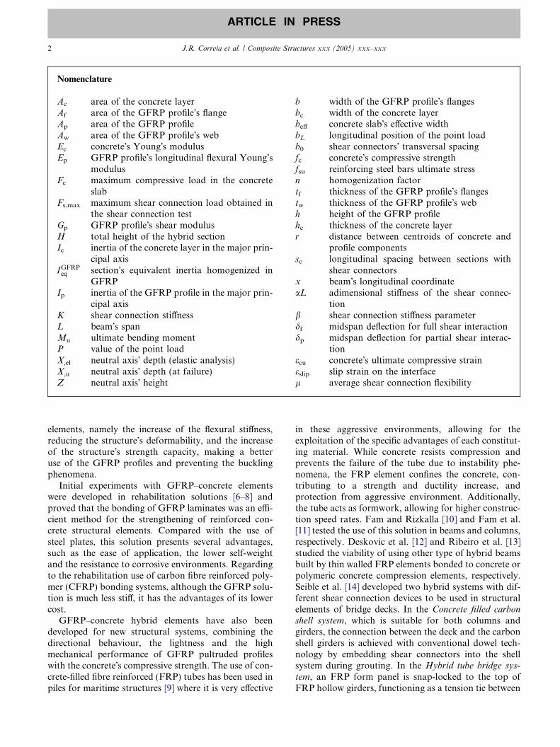
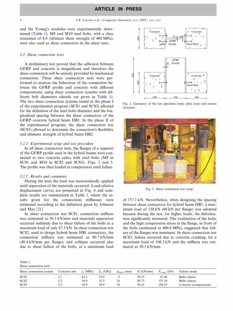
Fig. 2. Geometry of the test specimen (mm): plan (top) and section(bottom).
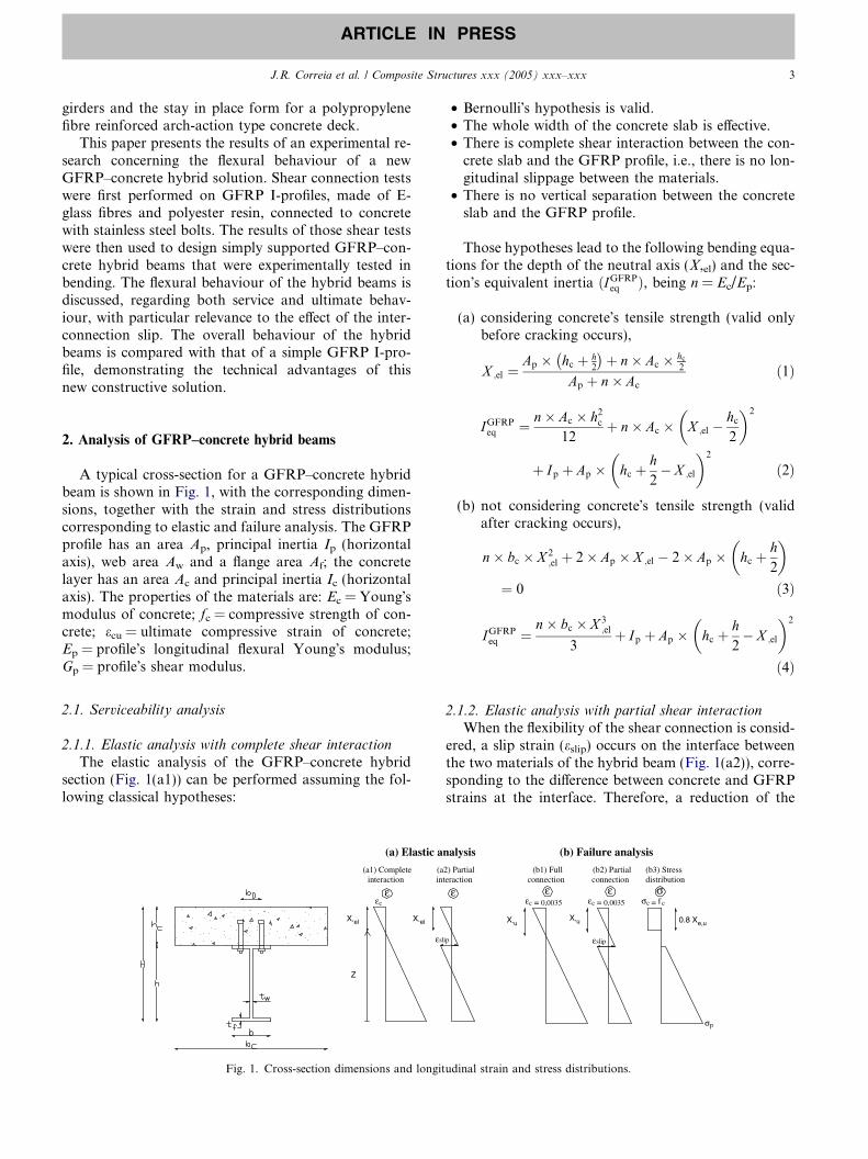
Fig. 3. Shear connection test setup.
3.2. Shear connection tests
A preliminary test proved that the adhesion betweenGFRP and concrete is insignificant and therefore theshear connection will be entirely provided by mechanicalconnection. Three shear connection tests were per-formed to analyze the behaviour of the connection be-tween the GFRP profile and concrete with differentcompositions, using shear connection systems with dif-ferent bolt diameters (details are given in Table 1).The two shear connection systems tested in the phase Iof the experimental program (SCS1 and SCS2) allowedfor the definition of the steel bolts diameter and the lon-gitudinal spacing between the shear connectors of theGFRP–concrete hybrid beam HB1. In the phase II ofthe experimental program, the shear connection test(SCS3) allowed to determine the connection�s flexibilityand ultimate strength of hybrid beam HB2.
3.2.1. Experimental setup and test procedure
In all shear connection tests, the flanges of a segmentof the GFRP profile used in the hybrid beams were con-nected to two concrete cubes with steel bolts (M8 inSCS1 and M10 in SCS2 and SCS3)—Figs. 2 and 3.The profile was then loaded in compression until failure.
3.2.2. Results and comments
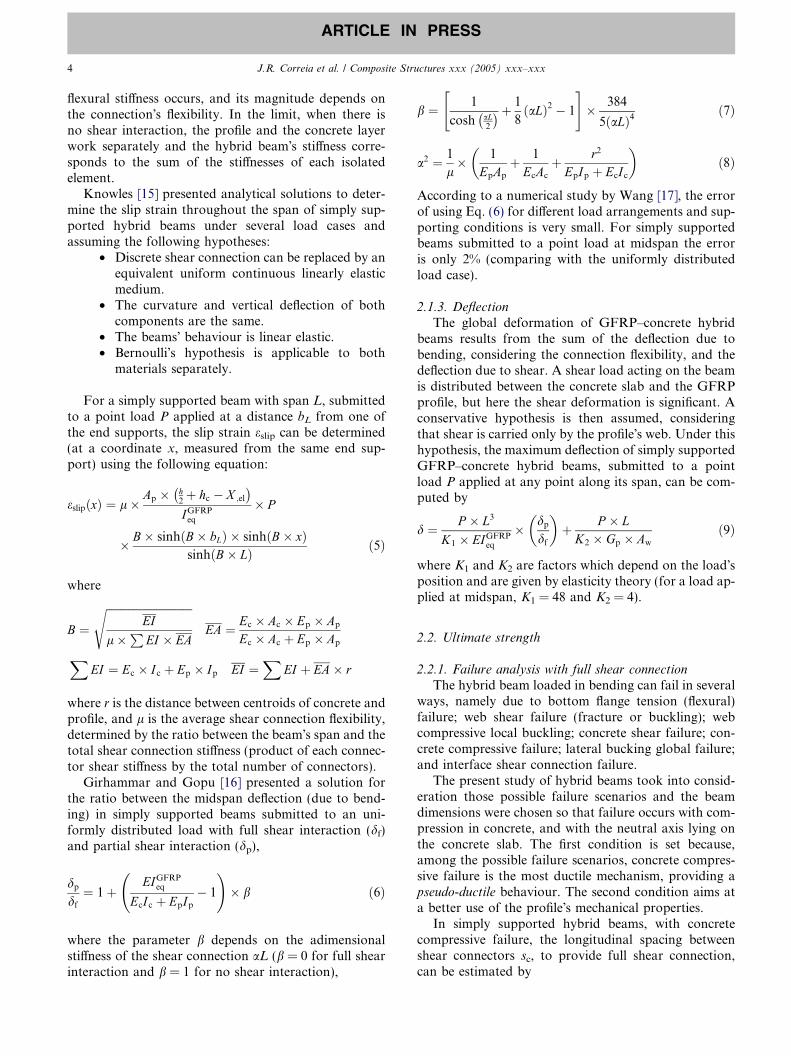
During the tests the load was monotonically applieduntil separation of the materials occurred. Load-relativedisplacement curves are presented in Fig. 4 and com-plete results are summarized in Table 1, where the re-sults given for the connections stiffnesses wereestimated according to the definition given by Johnsonand May [21].
In shear connection test SCS1, connection stiffnesswas estimated as 50.3 kN/mm and materials separationoccurred suddenly due to shear failure of the bolts at amaximum load of only 67.5 kN. In shear connection testSCS2, used to design hybrid beam HB1 connectors, theconnection stiffness was estimated as 80.7 kN/mm(40.4 kN/mm per flange), and collapse occurred alsodue to shear failure of the bolts, at a maximum load
Table 1Shear connection tests
Shear connection system Concrete mix fc (MPa) Ec (GPa) /bol
SCS1 C1 43.3 33.9 8SCS2 C2 39.9 32.5 10SCS3 C3 36.9 30.9 10
of 157.1 kN. Nevertheless, when designing the spacingbetween shear connectors for hybrid beam HB1, a max-imum load of 120 kN (60 kN per flange) was adoptedbecause during the test, for higher loads, the deforma-tion significantly increased. The ovalization of the holesand the high compression stress in the flange, in front ofthe bolts (estimated as 400.8 MPa), suggested that fail-ure of the flanges was imminent. In shear connection testSCS3, failure occurred due to concrete crushing, for amaximum load of 108.3 kN and the stiffness was esti-mated as 50.3 kN/mm.
ts (mm) K (kN/mm) Fs,max (kN) Failure mode
50.33 67.46 Bolts (shear)80.73 157.10 Bolts (shear)50.25 108.25 Concrete (compression)
0
20
40
60
80
100
120
140
160
180
0 2 5Average relative displacement (mm)
Loa
d (k
N) SCS3
SCS1
SCS2
3 4 6 71
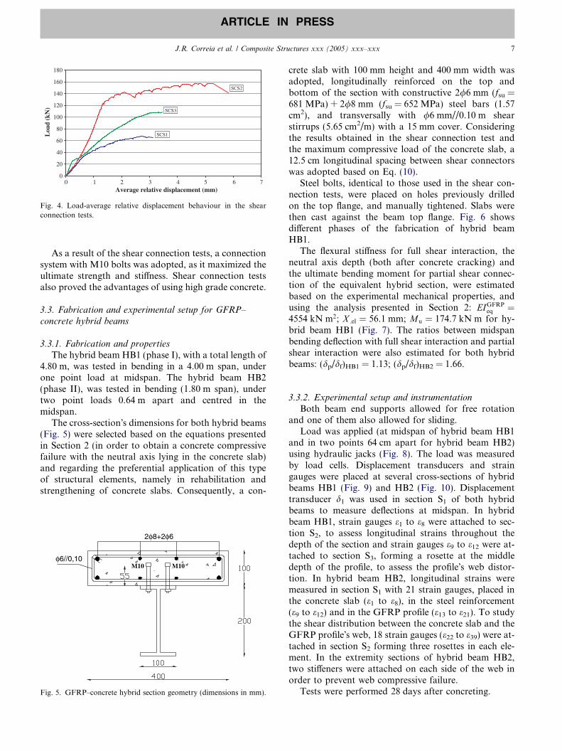
Fig. 4. Load-average relative displacement behaviour in the shearconnection tests.
J.R. Correia et al. / Composite Structures xxx (2005) xxx–xxx 7
ARTICLE IN PRESS
As a result of the shear connection tests, a connectionsystem with M10 bolts was adopted, as it maximized theultimate strength and stiffness. Shear connection testsalso proved the advantages of using high grade concrete.
3.3. Fabrication and experimental setup for GFRP–
concrete hybrid beams
3.3.1. Fabrication and properties
The hybrid beam HB1 (phase I), with a total length of4.80 m, was tested in bending in a 4.00 m span, underone point load at midspan. The hybrid beam HB2(phase II), was tested in bending (1.80 m span), undertwo point loads 0.64 m apart and centred in themidspan.
The cross-section�s dimensions for both hybrid beams(Fig. 5) were selected based on the equations presentedin Section 2 (in order to obtain a concrete compressivefailure with the neutral axis lying in the concrete slab)and regarding the preferential application of this typeof structural elements, namely in rehabilitation andstrengthening of concrete slabs. Consequently, a con-
φ6//0,10
2φ8+2φ6
M10 M10
Fig. 5. GFRP–concrete hybrid section geometry (dimensions in mm).
crete slab with 100 mm height and 400 mm width wasadopted, longitudinally reinforced on the top andbottom of the section with constructive 2/6 mm (fsu =681 MPa) + 2/8 mm (fsu = 652 MPa) steel bars (1.57cm2), and transversally with /6 mm//0.10 m shearstirrups (5.65 cm2/m) with a 15 mm cover. Consideringthe results obtained in the shear connection test andthe maximum compressive load of the concrete slab, a12.5 cm longitudinal spacing between shear connectorswas adopted based on Eq. (10).
Steel bolts, identical to those used in the shear con-nection tests, were placed on holes previously drilledon the top flange, and manually tightened. Slabs werethen cast against the beam top flange. Fig. 6 showsdifferent phases of the fabrication of hybrid beamHB1.
The flexural stiffness for full shear interaction, theneutral axis depth (both after concrete cracking) andthe ultimate bending moment for partial shear connec-tion of the equivalent hybrid section, were estimatedbased on the experimental mechanical properties, andusing the analysis presented in Section 2: EIGFRP
eq ¼4554 kN m2; X ;el ¼ 56.1 mm; Mu ¼ 174.7 kN m for hy-brid beam HB1 (Fig. 7). The ratios between midspanbending deflection with full shear interaction and partialshear interaction were also estimated for both hybridbeams: (dp/df)HB1 = 1.13; (dp/df)HB2 = 1.66.
3.3.2. Experimental setup and instrumentation
Both beam end supports allowed for free rotationand one of them also allowed for sliding.
Load was applied (at midspan of hybrid beam HB1and in two points 64 cm apart for hybrid beam HB2)using hydraulic jacks (Fig. 8). The load was measuredby load cells. Displacement transducers and straingauges were placed at several cross-sections of hybridbeams HB1 (Fig. 9) and HB2 (Fig. 10). Displacementtransducer d1 was used in section S1 of both hybridbeams to measure deflections at midspan. In hybridbeam HB1, strain gauges e1 to e8 were attached to sec-tion S2, to assess longitudinal strains throughout thedepth of the section and strain gauges e9 to e12 were at-tached to section S3, forming a rosette at the middledepth of the profile, to assess the profile�s web distor-tion. In hybrid beam HB2, longitudinal strains weremeasured in section S1 with 21 strain gauges, placed inthe concrete slab (e1 to e8), in the steel reinforcement(e9 to e12) and in the GFRP profile (e13 to e21). To studythe shear distribution between the concrete slab and theGFRP profile�s web, 18 strain gauges (e22 to e39) were at-tached in section S2 forming three rosettes in each ele-ment. In the extremity sections of hybrid beam HB2,two stiffeners were attached on each side of the web inorder to prevent web compressive failure.
Tests were performed 28 days after concreting.
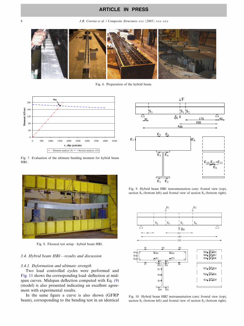
Fig. 6. Preparation of the hybrid beam.
0
40
80
120
160
200
0 500 1000 1500 2000 2500 3000 3500 4000 4500
ε , slip (µstrain)
Mom
ent
(kN
.m)
Element analysis (5) Section analysis (15)
Mu
Fig. 7. Evaluation of the ultimate bending moment for hybrid beamHB1.
Fig. 8. Flexural test setup—hybrid beam HB1.
ε7
S3 S1 S2
ε5 ε6
ε8
ε3 ε4
ε1 ε2
ε10
ε9
ε11 ε12
δ1
F
Fig. 9. Hybrid beam HB1 instrumentation (cm): frontal view (top),section S2 (bottom left) and frontal view of section S3 (bottom right).
εεε
ε
ε ε
ε
ε
εε
ε
ε
εε
εε
ε
ε ε
ε
ε
εε
ε εε
ε ε εε
ε
εε
ε
εε
εεε
δ1
F1
S3S2
F2
S4S1
Fig. 10. Hybrid beam HB2 instrumentation (cm): frontal view (top),section S1 (bottom left) and frontal view of section S2 (bottom right).
8 J.R. Correia et al. / Composite Structures xxx (2005) xxx–xxx
ARTICLE IN PRESS
3.4. Hybrid beam HB1—results and discussion
3.4.1. Deformation and ultimate strength
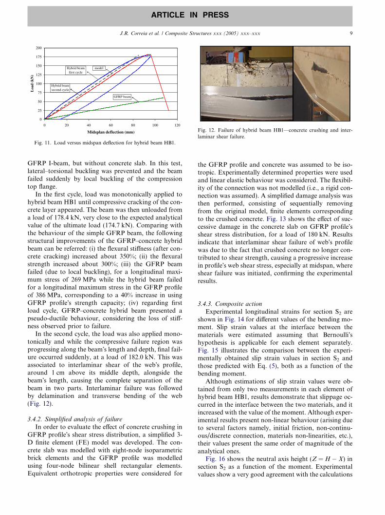
Two load controlled cycles were performed andFig. 11 shows the corresponding load–deflection at mid-span curves. Midspan deflection computed with Eq. (9)(model) is also presented indicating an excellent agree-ment with experimental results.
In the same figure a curve is also shown (GFRPbeam), corresponding to the bending test in an identical
0
25
50
75
100
125
150
175
200
0 20 40 60 80 100 120
Midsplan deflection (mm)
Loa
d (k
N)
Hybrid beamfirst cycle
Hybrid beamsecond cycle
GFRP beam
model
Fig. 11. Load versus midspan deflection for hybrid beam HB1.
Fig. 12. Failure of hybrid beam HB1—concrete crushing and inter-laminar shear failure.
J.R. Correia et al. / Composite Structures xxx (2005) xxx–xxx 9
ARTICLE IN PRESS
GFRP I-beam, but without concrete slab. In this test,lateral–torsional buckling was prevented and the beamfailed suddenly by local buckling of the compressiontop flange.
In the first cycle, load was monotonically applied tohybrid beam HB1 until compressive cracking of the con-crete layer appeared. The beam was then unloaded froma load of 178.4 kN, very close to the expected analyticalvalue of the ultimate load (174.7 kN). Comparing withthe behaviour of the simple GFRP beam, the followingstructural improvements of the GFRP–concrete hybridbeam can be referred: (i) the flexural stiffness (after con-crete cracking) increased about 350%; (ii) the flexuralstrength increased about 300%; (iii) the GFRP beamfailed (due to local buckling), for a longitudinal maxi-mum stress of 269 MPa while the hybrid beam failedfor a longitudinal maximum stress in the GFRP profileof 386 MPa, corresponding to a 40% increase in usingGFRP profile�s strength capacity; (iv) regarding firstload cycle, GFRP–concrete hybrid beam presented apseudo-ductile behaviour, considering the loss of stiff-ness observed prior to failure.
In the second cycle, the load was also applied mono-tonically and while the compressive failure region wasprogressing along the beam�s length and depth, final fail-ure occurred suddenly, at a load of 182.0 kN. This wasassociated to interlaminar shear of the web�s profile,around 1 cm above its middle depth, alongside thebeam�s length, causing the complete separation of thebeam in two parts. Interlaminar failure was followedby delamination and transverse bending of the web(Fig. 12).
3.4.2. Simplified analysis of failure
In order to evaluate the effect of concrete crushing inGFRP profile�s shear stress distribution, a simplified 3-D finite element (FE) model was developed. The con-crete slab was modelled with eight-node isoparametricbrick elements and the GFRP profile was modelledusing four-node bilinear shell rectangular elements.Equivalent orthotropic properties were considered for
the GFRP profile and concrete was assumed to be iso-tropic. Experimentally determined properties were usedand linear elastic behaviour was considered. The flexibil-ity of the connection was not modelled (i.e., a rigid con-nection was assumed). A simplified damage analysis wasthen performed, consisting of sequentially removingfrom the original model, finite elements correspondingto the crushed concrete. Fig. 13 shows the effect of suc-cessive damage in the concrete slab on GFRP profile�sshear stress distribution, for a load of 180 kN. Resultsindicate that interlaminar shear failure of web�s profilewas due to the fact that crushed concrete no longer con-tributed to shear strength, causing a progressive increasein profile�s web shear stress, especially at midspan, whereshear failure was initiated, confirming the experimentalresults.
3.4.3. Composite action
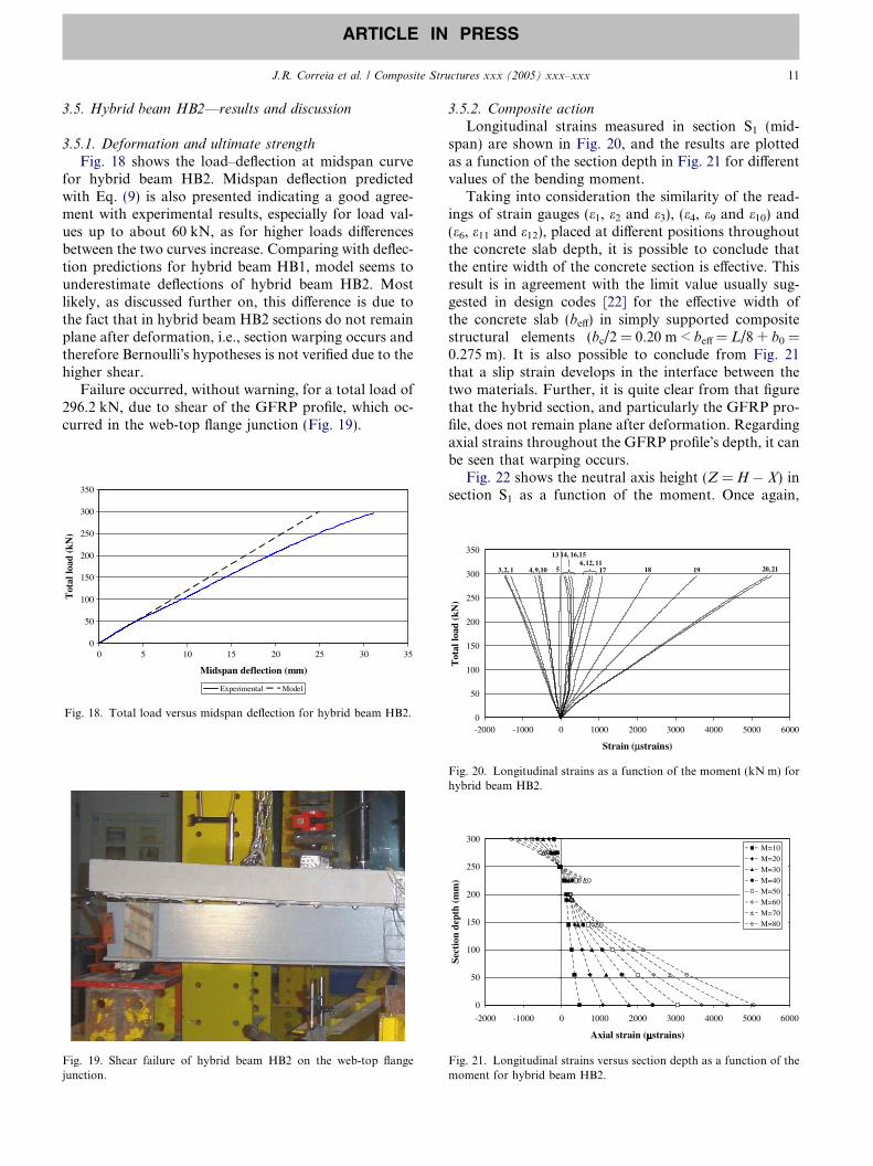
Experimental longitudinal strains for section S2 areshown in Fig. 14 for different values of the bending mo-ment. Slip strain values at the interface between thematerials were estimated assuming that Bernoulli�shypothesis is applicable for each element separately.Fig. 15 illustrates the comparison between the experi-mentally obtained slip strain values in section S2 andthose predicted with Eq. (5), both as a function of thebending moment.
Although estimations of slip strain values were ob-tained from only two measurements in each element ofhybrid beam HB1, results demonstrate that slippage oc-curred in the interface between the two materials, and itincreased with the value of the moment. Although exper-imental results present non-linear behaviour (arising dueto several factors namely, initial friction, non-continu-ous/discrete connection, materials non-linearities, etc.),their values present the same order of magnitude of theanalytical ones.
Fig. 16 shows the neutral axis height (Z = H � X) insection S2 as a function of the moment. Experimentalvalues show a very good agreement with the calculations
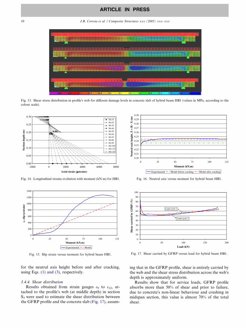
Fig. 13. Shear stress distribution in profile�s web for different damage levels in concrete slab of hybrid beam HB1 (values in MPa, according to thecolour scale).
0.00
0.05
0.10
0.15
0.20
0.25
0.30
-2000 0 2000 4000 6000 8000
Axial strain (µµµµstrains)
Sect
ion
dept
h (m
) εεεε.slip
M=10M=20M=30M=40
M=50M=60M=70M=80M=90M=100M=110M=120
Fig. 14. Longitudinal strains evolution with moment (kN m) for HB1.
0
200
400
600
800
1000
1200
1400
0 25 50 75 100 125
Moment (kN.m)
µε,
slip
(st
rain
)
Experimental Model
Fig. 15. Slip strain versus moment for hybrid beam HB1.
0.20
0.21
0.22
0.23
0.24
0.25
0.26
0.27
0.28
0.29
0.30
0 25 50 75 100 125
Moment (kN.m)
Neu
tral
axi
s he
ight
, Z =
H -
X (m
)
Experimental Model before cracking Model after cracking
Fig. 16. Neutral axis versus moment for hybrid beam HB1.
0
10
20
30
40
50
60
70
80
90
100
0 50 100 150 200
Load (kN)
Shea
r ca
rrie
d by
GFR
P (%
)
Load cycle 1
Load cycle 2
Fig. 17. Shear carried by GFRP versus load for hybrid beam HB1.
10 J.R. Correia et al. / Composite Structures xxx (2005) xxx–xxx
ARTICLE IN PRESS
for the neutral axis height before and after cracking,using Eqs. (1) and (3), respectively.
3.4.4. Shear distributionResults obtained from strain gauges e9 to e12, at-
tached to the profile�s web (at middle depth) in sectionS3 were used to estimate the shear distribution betweenthe GFRP profile and the concrete slab (Fig. 17), assum-
ing that in the GFRP profile, shear is entirely carried bythe web and the shear stress distribution across the web�sdepth is approximately uniform.
Results show that for service loads, GFRP profileabsorbs more than 50% of shear and prior to failure,due to concrete�s non-linear behaviour and crushing inmidspan section, this value is almost 70% of the totalshear.
J.R. Correia et al. / Composite Structures xxx (2005) xxx–xxx 11
ARTICLE IN PRESS
3.5. Hybrid beam HB2—results and discussion
3.5.1. Deformation and ultimate strength
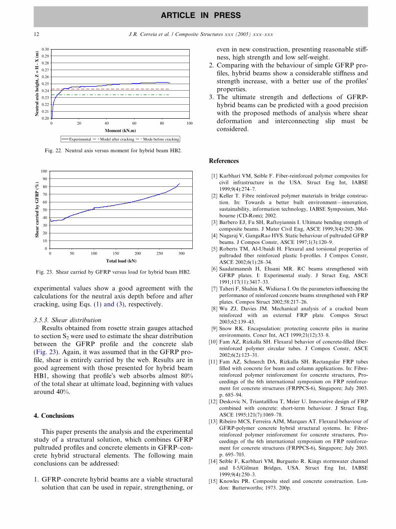
Fig. 18 shows the load–deflection at midspan curvefor hybrid beam HB2. Midspan deflection predictedwith Eq. (9) is also presented indicating a good agree-ment with experimental results, especially for load val-ues up to about 60 kN, as for higher loads differencesbetween the two curves increase. Comparing with deflec-tion predictions for hybrid beam HB1, model seems tounderestimate deflections of hybrid beam HB2. Mostlikely, as discussed further on, this difference is due tothe fact that in hybrid beam HB2 sections do not remainplane after deformation, i.e., section warping occurs andtherefore Bernoulli�s hypotheses is not verified due to thehigher shear.
Failure occurred, without warning, for a total load of296.2 kN, due to shear of the GFRP profile, which oc-curred in the web-top flange junction (Fig. 19).
0
50
100
150
200
250
300
350
0 5 10 15 20 25 30 35
Midspan deflection (mm)
Tot
al lo
ad (
kN)
Experimental Model
Fig. 18. Total load versus midspan deflection for hybrid beam HB2.
Fig. 19. Shear failure of hybrid beam HB2 on the web-top flangejunction.
3.5.2. Composite action
Longitudinal strains measured in section S1 (mid-span) are shown in Fig. 20, and the results are plottedas a function of the section depth in Fig. 21 for differentvalues of the bending moment.
Taking into consideration the similarity of the read-ings of strain gauges (e1, e2 and e3), (e4, e9 and e10) and(e6, e11 and e12), placed at different positions throughoutthe concrete slab depth, it is possible to conclude thatthe entire width of the concrete section is effective. Thisresult is in agreement with the limit value usually sug-gested in design codes [22] for the effective width ofthe concrete slab (beff) in simply supported compositestructural elements (bc/2 = 0.20 m < beff = L/8 + b0 =0.275 m). It is also possible to conclude from Fig. 21that a slip strain develops in the interface between thetwo materials. Further, it is quite clear from that figurethat the hybrid section, and particularly the GFRP pro-file, does not remain plane after deformation. Regardingaxial strains throughout the GFRP profile�s depth, it canbe seen that warping occurs.
Fig. 22 shows the neutral axis height (Z = H � X) insection S1 as a function of the moment. Once again,
0
50
100
150
200
250
300
350
-2000 -1000 0 1000 2000 3000 4000 5000 6000
Strain (µstrains)
Tot
al lo
ad (
kN)
3,2, 1 4,9,10 5
13 14, 16,156,12, 11
17 18 19 20,21
Fig. 20. Longitudinal strains as a function of the moment (kN m) forhybrid beam HB2.
0
50
100
150
200
250
300
-2000 -1000 0 1000 2000 3000 4000 5000 6000
Axial strain (µµµµstrains)
Sect
ion
dept
h (m
m)
M=10M=20M=30M=40M=50M=60M=70M=80
Fig. 21. Longitudinal strains versus section depth as a function of themoment for hybrid beam HB2.
0
10
20
30
40
50
60
70
80
90
100
0 50 100 150 200 250 300
Total load (kN)
Shea
r ca
rrie
d by
GF
RP
(%)
Fig. 23. Shear carried by GFRP versus load for hybrid beam HB2.
0.20
0.21
0.22
0.23
0.24
0.25
0.26
0.27
0.28
0.29
0.30
0 20 40 60 80
Moment (kN.m)
Neu
tral
axi
s he
ight
, Z =
H -
X (m
)
100
Experimental Model after cracking Mode before cracking
Fig. 22. Neutral axis versus moment for hybrid beam HB2.
12 J.R. Correia et al. / Composite Structures xxx (2005) xxx–xxx
ARTICLE IN PRESS
experimental values show a good agreement with thecalculations for the neutral axis depth before and aftercracking, using Eqs. (1) and (3), respectively.
3.5.3. Shear distribution
Results obtained from rosette strain gauges attachedto section S2 were used to estimate the shear distributionbetween the GFRP profile and the concrete slab(Fig. 23). Again, it was assumed that in the GFRP pro-file, shear is entirely carried by the web. Results are ingood agreement with those presented for hybrid beamHB1, showing that profile�s web absorbs almost 80%of the total shear at ultimate load, beginning with valuesaround 40%.
4. Conclusions
This paper presents the analysis and the experimentalstudy of a structural solution, which combines GFRPpultruded profiles and concrete elements in GFRP–con-crete hybrid structural elements. The following mainconclusions can be addressed:
1. GFRP–concrete hybrid beams are a viable structuralsolution that can be used in repair, strengthening, or
even in new construction, presenting reasonable stiff-ness, high strength and low self-weight.
2. Comparing with the behaviour of simple GFRP pro-files, hybrid beams show a considerable stiffness andstrength increase, with a better use of the profiles�properties.
3. The ultimate strength and deflections of GFRP-hybrid beams can be predicted with a good precisionwith the proposed methods of analysis where sheardeformation and interconnecting slip must beconsidered.
References
[1] Karbhari VM, Seible F. Fiber-reinforced polymer composites forcivil infrastructure in the USA. Struct Eng Int, IABSE1999;9(4):274–7.
[2] Keller T. Fibre reinforced polymer materials in bridge construc-tion. In: Towards a better built environment—innovation,sustainability, information technology, IABSE Symposium, Mel-bourne (CD-Rom); 2002.
[3] Barbero EJ, Fu SH, Raftoyiannis I. Ultimate bending strength ofcomposite beams. J Mater Civil Eng, ASCE 1999;3(4):292–306.
[4] Nagaraj V, GangaRao HVS. Static behaviour of pultruded GFRPbeams. J Compos Constr, ASCE 1997;1(3):120–9.
[5] Roberts TM, Al-Ubaidi H. Flexural and torsional properties ofpultruded fiber reinforced plastic I-profiles. J Compos Constr,ASCE 2002;6(1):28–34.
[6] Saadatmanesh H, Ehsani MR. RC beams strengthened withGFRP plates. I: Experimental study. J Struct Eng, ASCE1991;117(11):3417–33.
[7] Taheri F, Shahin K, Widiarsa I. On the parameters influencing theperformance of reinforced concrete beams strengthened with FRPplates. Compos Struct 2002;58:217–26.
[8] Wu ZJ, Davies JM. Mechanical analysis of a cracked beamreinforced with an external FRP plate. Compos Struct2003;62:139–43.
[9] Snow RK. Encapsulation: protecting concrete piles in marineenvironments. Concr Int, ACI 1999;21(12):33–8.
[10] Fam AZ, Rizkalla SH. Flexural behavior of concrete-filled fiber-reinforced polymer circular tubes. J Compos Constr, ASCE2002;6(2):123–31.
[11] Fam AZ, Schnerch DA, Rizkalla SH. Rectangular FRP tubesfilled with concrete for beam and column applications. In: Fibre-reinforced polymer reinforcement for concrete structures, Pro-ceedings of the 6th international symposium on FRP reinforce-ment for concrete structures (FRPPCS-6), Singapore; July 2003.p. 685–94.
[12] Deskovic N, Triantafillou T, Meier U. Innovative design of FRPcombined with concrete: short-term behaviour. J Struct Eng,ASCE 1995;121(7):1069–78.
[13] Ribeiro MCS, Ferreira AJM, Marques AT. Flexural behaviour ofGFRP-polymer concrete hybrid structural systems. In: Fibre-reinforced polymer reinforcement for concrete structures, Pro-ceedings of the 6th international symposium on FRP reinforce-ment for concrete structures (FRPPCS-6), Singapore; July 2003.p. 695–703.
[14] Seible F, Karbhari VM, Burgueno R. Kings stormwater channeland I-5/Gilman Bridges, USA. Struct Eng Int, IABSE1999;9(4):250–3.
[15] Knowles PR. Composite steel and concrete construction. Lon-don: Butterworths; 1973. 200p.

J.R. Correia et al. / Composite Structures xxx (2005) xxx–xxx 13
ARTICLE IN PRESS
[16] Girhammar UA, Gopu KA. Composite beam-columns withinterlayer Slip—exact analysis. J Struct Eng, ASCE 1993;119(4):1265–82.
[17] Wang YC. Deflection of steel-concrete composite beams with par-tial shear interaction. J Struct Eng, ASCE 1998;124(10):1159–65.
[18] Correia JR. Glass fibre reinforced polymer (GFRP) pultrudedprofiles. Structural behaviour of GFRP–concrete hybrid beams.MSc Thesis, Instituto Superior Tecnico, 2004 [in Portuguese].
[19] Branco FA, Ferreira J, Correia JR. The use of GRC and GFRP–concrete beams in bridge decks. In: FRP composites in bridge
design and civil engineering, COBRAE Conference Proceedings,Porto; November 2003.
[20] Bank LC. Flexural and shear moduli of full-section fiberreinforced plastic (FRP) pultruded beams. J Test Eval, ASTM1989;17(1):40–5.
[21] Johnson RP, May IM. Partial-interaction design of compositebeams. Struct Engr 1975;53(8):305–11.
[22] Design of composite steel and concrete structures. Part 1.1:General rules and rules for buildings. Eurocode No. 4; 1992.