Embed Size (px)
Citation preview
PREDICTING CRACK PATTERN ON ARCHIMEDES SCREW RUNNER BLADE OF
MICRO HYDRO POWER
AHMAD ALIF BIN AHMAD ADAM
A report submitted in partial fulfilment of the requirements for the award of the degree of
Bachelor of Mechanical Engineering
Faculty of Mechanical Engineering
UNIVERSITY MALAYSIA PAHANG
JUNE 2013

vii
ABSTRACT
One of the fundamental studies of Micro hydro power with low head is the
Archimedes screw runner. This research focuses on the study of behavior of fluid flow
acting on the Archimedes screw runner blade and prediction of erosion pattern from
fluid flow. The CAD model of the Archimedes screw blade was re-inversely design
from past researcher. In order to determine the flow pattern, computational fluid
dynamic, CFD was used to obtain the pressure distribution along blade structure.
Analysis of three-dimensional with steady state flow was done with a standard k-ε as
the turbulence model. The result obtained from pressure pattern shows that the highest
value of coefficient of pressure obtained at the blade tip. This result shows that the
prediction of crack may occur mostly at the blade tip. Further studies of blade design
can be improved by reducing crack.
Keywords: CFD, Archimedes screw runner blade, Micro hydro Power, Crack Pattern

viii
ABSTRAK
Pelari skru Archimedes merupakan salah satu kajian asas kuasa micro hidro
dengan kepala rendah. Kajian ini memberi tumpuan kepada kajian terhadap tingkah laku
aliran cecair yang bertindak atas Archimedes skru bilah pelari dan ramalan corak
hakisan daripada aliran cecair. Model CAD daripada bilah skru Archimedes adalah reka
bentuk semula daripada penyelidik yang lepas. Dalam usaha untuk menentukan corak
aliran, pengiraan cecair dinamik, CFD telah digunakan untuk mendapatkan corak
tekanan sepanjang struktur bilah. Analisis tiga dimensi dengan aliran yang setabil telah
dilakukan dengan k-ε standard sebagai model terbulent. Keputusan yang diperolehi dari
corak tekanan menunjukkan bahawa nilai tertinggi pekali tekanan didapati di hujung
bilah. Keputusan ini menunjukkan bahawa ramalan keretakan boleh berlaku
kebanyakannya di hujung bilah. Reka bentuk bilah pada kajian akn dating boleh
diperbaiki dengan mengurangkan retak.
Kata kunci: CFD, Bilah Skru Archimedes, Jana Kuasa Mikro Hidro, Corak Tekanan

ix
TABLE OF CONTENTS
Page
EXAMINER’S DECLARATION ii
SUPERVISOR DECLARATION iii
STUDENT DECLARATION iv
DEDICATION v
ACKNOWLEDGEMENT vi
ABSTRACT vii
TABLE OF CONTENTS ix
LIST OF TABLE xi
LIST OF FIGURE xii
LIST OF ABBREVIATIONS xiv
NOMENCLATURES xv
CHAPTER 1 INTRODUCTION
1.1 Micro Hydro Power 1
1.2 Archimedes Screw Turbine 2
1.3 Problem Statements 3
1.4 Objectives 3
1.5 Scopes 3
CHAPTER 2 LITERATURE REVIEW
2.1 Introduction 4
2.2 Archimedes Screw Blade 4
2.2.1 Screw Blade Design 6
2.3 Governing Equation 8
2.4 Blade Optimum Rotation 10
2.5 Fatigue Crack 11
2.6 Crack Pattern Simulation 15

x
2.7 Velocity of Pahang River 17
2.8 Conclusion on the Literature Review 17
CHAPETR 3 METHODOLOGY
3.1 Introduction 18
3.2 Flow Chart 18
3.3 CAD Modeling 21
3.4 Meshing (ANSYS CFX) 23
3.5 Simulation 24
3.5.1 Boundary Condition 25
3.5.2 Imaginary Boundary 26
3.6 Simulation of the Flow 27
CHAPTER 4 RESULT AND DISCUSSION
4.1 Introduction 29
4.2 Result of Velocity Pattern 29
4.3 Result of Pressure Pattern 31
4.4 Pressure Distribution on the 14 Screw
Runner Blade
32
4.5 Velocity Distribution on the 14 Screw
Runner Blade
35
4.6 Coefficient of Pressure of the 14 Screw
Runner Blade
36
CAHPTER 5 CONCLUSION AND RECOMDENTADION
5.1 Introduction 40
5.2 Conclusion 40
5.3 Recommendation 41
REFFERENCES 42
APPENDICES 43

xi
LIST OF TABLE
Table No.
Title Page
3.1 Dimension of the screw runner blade 22
3.2 Dimension of the flow path
23
3.3 Meshing detail of the flow path and screw runner blade
24
3.4 Default domain details
26
3.5 Inlet boundary and Outlet boundary details
27

xii
LIST OF FIGURE
Figure No.
Title Page
2.1
The structure of Archimedes screw turbine 5
2.2
(a) Idealize Archimedes screw side and plan view (b)
Hydrostatic pressure wheel (c) Force acting on individual
screw blade
6
2.3
General external and internal parameter of Archimedes screw 7
2.4
CAD model for Archimedes screw 8
2.5 The theoretical efficiency as function of sloe angle and
number of helical turns
11
2.6
Analysis using of the Francis turbine using computer
simulation (b) Real image of the crack occurrence at the
Francis turbine
12
2.7
(a) The crack propagation on the wind turbine blade (b) The
simulation of the pressure distribution on the wind turbine
blade
13
2.8
(a) The microstructure of the crack initiation (b) the
distribution of stress at the gas turbine blade
14
2.9
(a) The fluid flow visual from ANSYS on Francis turbine (b)
The pressure distribution from ANSYS on Francis turbine
15
2.10
Imaginary space on ANSYS 16
3.1
Flow chart for Semester 1 FYP progress 19
3.2
Flow chart for Semester 2 FYP progress 18
3.3
(a) Wireframe view and (b) Hidden line visible view of the
screw runner blade with flow path on SolidWork
21-22
3.4 Mesh structure of the flow path and screw runner blade 24
3.5 The boundary condition setup for the simulation
25
3.6 The imaginary boundary for water flow inlet and outlet
26
3.7 Velocity vector view at the flow path
28
3.8 Graph of velocity versus flow path distance
28
xiii
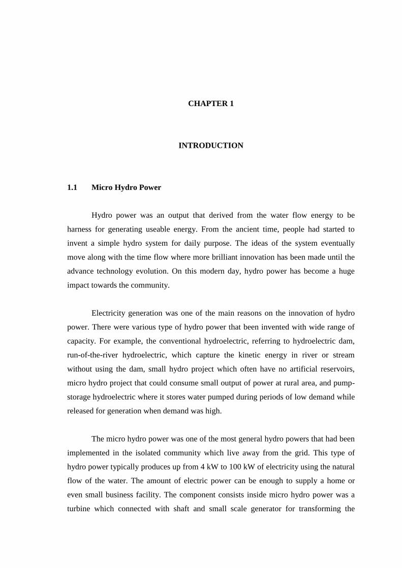
LIST OF FIGURES
Figure No.
Title Page
4.1 Velocity distribution plane view at the flow path
30
4.2
Velocity vector view at the flow path 30
4.3
Pressure contour view at the screw runner blade 31
4.4 Pressure plane view at the screw runner blade
32
4.5
14 helical blade pressure contour views 33
4.6 Location of leading edge, blade tip and blade surface
33
4.7 Graph of Pressure versus Blade Distance
34
4.8 Graph of velocity versus blade distance 35
4.9 Coefficient of pressure distribution on plane view 36
4.10 Coefficient of pressure contour view at the screw runner blade 37
4.11 Plotted point at leading edge, blade tip and blade surface of
the screw blade
37
4.12 Graph of coefficient of pressure versus blade distance 38

xiv
LIST OF ABBREVIATIONS
CAD Computer Aided Design
CFD Computational Fluid Dynamics
Cp Coefficient of Pressure
areaAve Average area
LE Leading edge
BT Blade tip
BS Blade surface

xv
NOMENCLATURES
kW Kilo Watt
Density of fluid
t Time
Normal Stress for the momentum equation
normal viscous stress for the momentum equation
k Kinematic energy
Dissipation energy
S Modulus of the mean rate-of-strain tensor
P Pressure Difference
W Blade surface velocity
Pitch
Rₒ Outer radius
Rᵢ Inner radius
N Number of blade revolution
L Blade length
K Slope
H Head
Pa Pascal
m Meter
C Degree Celsius
1
CHAPTER 1
INTRODUCTION
1.1 Micro Hydro Power
Hydro power was an output that derived from the water flow energy to be
harness for generating useable energy. From the ancient time, people had started to
invent a simple hydro system for daily purpose. The ideas of the system eventually
move along with the time flow where more brilliant innovation has been made until the
advance technology evolution. On this modern day, hydro power has become a huge
impact towards the community.
Electricity generation was one of the main reasons on the innovation of hydro
power. There were various type of hydro power that been invented with wide range of
capacity. For example, the conventional hydroelectric, referring to hydroelectric dam,
run-of-the-river hydroelectric, which capture the kinetic energy in river or stream
without using the dam, small hydro project which often have no artificial reservoirs,
micro hydro project that could consume small output of power at rural area, and pump-
storage hydroelectric where it stores water pumped during periods of low demand while
released for generation when demand was high.
The micro hydro power was one of the most general hydro powers that had been
implemented in the isolated community which live away from the grid. This type of
hydro power typically produces up from 4 kW to 100 kW of electricity using the natural
flow of the water. The amount of electric power can be enough to supply a home or
even small business facility. The component consists inside micro hydro power was a
turbine which connected with shaft and small scale generator for transforming the

2
rotational energy into electric energy. For most of the micro hydropower, there were
few common turbine blade type used such as Francis blade, Pelton blade, Kaplan blade,
Archimedes blade and etc. the Archimedes blade usually used on low head with high
water flow condition. The blade can work efficiently up to on heads as low as 1 meter.
The maximum turbine efficiency that can be performed by the Archimedes blade was up
to 90 percent as the flow rate increased. Single screws could work on heads up to 8
meters, but above the head level, multiple screws are generally used. Three screw blades
were commonly found for this type of hydro power.
As for the conclusion, the Archimedes or screw runner for micro hydro power
could consume higher efficiency similar with other type of hydro turbine. Even so the
main purpose of the micro hydro turbine was to generate enough amount of electricity
for the comfort of certain community that live at rural region in this world.
1.2 Archimedes Screw Turbine
Micro hydropower could consume electricity with higher in turbine efficiency
even the turbine type used was low head turbine especially for Archimedes screw
turbine. The Archimedean screw pump was one of the oldest hydraulic machines.
Today, it was employed in pumping as well as operating in reverse in an energy
conversion role for producing useful energy. Despite its age, no consistent theory links
the screw’s geometry with its mechanical efficiency. The research on the fatigue crack
towards the Archimedes blade also still in finding and thus for obtaining the problem
solution more of this low head turbine had been implemented at all around the world.
Even so, this type of turbine only been implemented at rural area where the community
lives were far away from the main grid. This also due to the other used of turbine that
produce much more energy compare to Archimedes crew turbine. Thus in order
encounters the entire problem related with Archimedes blade, the implementation of the
turbine was very important for elaborating the solution for each of the problem that will
occur in a normal operating turbine blade.

3
1.3 Problem Statements
The loss of turbine efficiency on the micro hydro power was caused from the
crack occur on the turbine blade. The type of turbine blade that used for the micro hydro
power was Archimedes screw blade. An analysis has to be made on the fluid flow
behavior towards the blade to obtain the prediction of flow where the probability of
crack might happen.
1.4 Objectives
The objectives for this project were:-
Developed the CAD model blade using the existing blade dimension.
To study the behavior of fluid flow acting at the screw runner.
To predict the crack behavior to the screw runner blade of Micro Hydro Power.
1.5 Scopes
In order to accomplish the project objectives, the scopes that need to be listed for
the project were as follows,
1. Develop CAD model of the screw runner blade with dimension based from the
previous researcher.
2. Meshing the develop CAD model using the ANSYS CFX software.
3. Assuming the fluid medium for the analysis as water in steady state flow,
isothermal condition, and isentropic condition.
4. Creating the boundary details for the analysis of the model where the boundary
was based on real structure.
5. K epsilon turbulence model will be taken as the solver of the analysis.
6. The flow velocity used is at 2.5 m/s assuming the flow of the river in Malaysia.

4
CHAPTER 2
LITERATURE REVIEW
2.1 Introduction
In this chapter we will be discuss about the character and function of
Archimedes screw blade and also the design of the blade model. Besides that, the
review on fatigue crack prediction analysis on turbomachinary will be further discussed
on this chapter.
2.2 Archimedes Screw Blade
One of the main parts in hydro power was the turbine blade itself. The turbine
blade reaction towards water flow creates a rotational motion for the hydro power to
generate electricity. There was various type of turbine blade that we can found now
days. Archimedes screw blade was one of the turbine blade used in micro hydro power.
Archimedes screw consists of helical blades which surround the central shaft.
Back to the old days, the screw blades was a device for lifting water for irrigation and
drainage purposes (Rorres et al., 1999) especially from lower to higher area. The blade
will be rotated by using a windmill or by manual man power. As the shaft turns, the
bottom end of the blade scoops up a volume of water. This water will slide up in the
spiral tube, until it finally pours out from the top of the tube and passes into the desired
reserve water tank for other daily purpose. The Archimedes screw also had been applied
for draining water out of mines. On this modern world, people start to reused and also
redesign the blade concept from a pump purpose function to a turbine for generating
electricity. On the modern blade design, the screw will be rotated by the water referring
5
to figure 2.1as the water was channeled on to the blade channel from higher area to
lower area. But the slope involve was not very large since the water flow give enough
force to rotate the shaft.
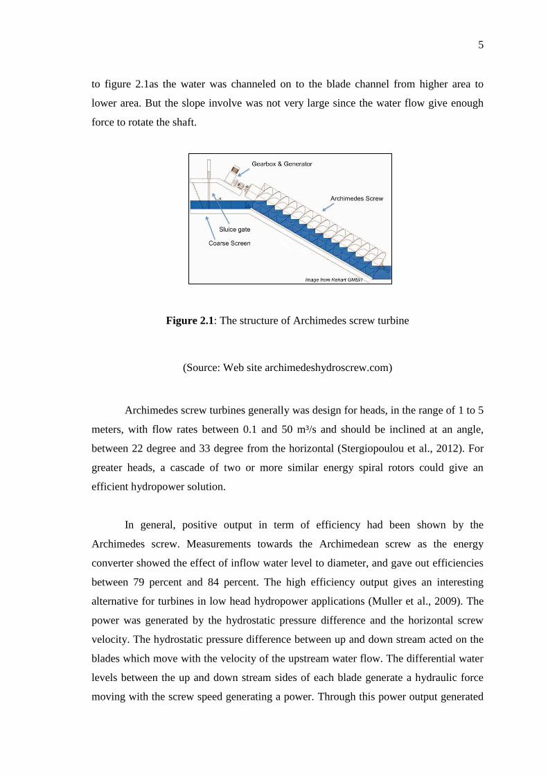
Figure 2.1: The structure of Archimedes screw turbine
(Source: Web site archimedeshydroscrew.com)
Archimedes screw turbines generally was design for heads, in the range of 1 to 5
meters, with flow rates between 0.1 and 50 m³/s and should be inclined at an angle,
between 22 degree and 33 degree from the horizontal (Stergiopoulou et al., 2012). For
greater heads, a cascade of two or more similar energy spiral rotors could give an
efficient hydropower solution.
In general, positive output in term of efficiency had been shown by the
Archimedes screw. Measurements towards the Archimedean screw as the energy
converter showed the effect of inflow water level to diameter, and gave out efficiencies
between 79 percent and 84 percent. The high efficiency output gives an interesting
alternative for turbines in low head hydropower applications (Muller et al., 2009). The
power was generated by the hydrostatic pressure difference and the horizontal screw
velocity. The hydrostatic pressure difference between up and down stream acted on the
blades which move with the velocity of the upstream water flow. The differential water
levels between the up and down stream sides of each blade generate a hydraulic force
moving with the screw speed generating a power. Through this power output generated

6
by the blade, minimum efficiency of the turbine can be obtained from the calculation
using efficiency formulation.
Figure 2.2: (a) Idealize Archimedes screw side and plan view (b) Hydrostatic pressure
wheel (c) Force acting on individual screw blade
(Source:Geraled Muller et al., 2009)
2.2.1 Screw Blade Design
The geometry of helical screw blade was developed through a certain external
parameters and also internal parameters. Both parameter lists were outer radius, length,
and slope for external and the inner radius, number of blades, and the pitch of the blades
for the internal parameters. The external parameters were usually determined by the
location of the screw and how much water volume that will be transfer. While, the
internal parameters were free to be chosen to optimize the performance of the screw
(Rorres et al., 1999).
(a)
(b) (c)

7
Referring from figure 2.3, the external and internal parameters were the:
External parameter,
Rₒ, radius of the outer cylinder
L, length of the screw blade
K, slope of screw blade
Internal parameter,
Rᵢ, radius of the inner cylinder
ᴧ, pitch (or period) of on blade
N, number of blade
Figure 2.3: General external and internal parameter of Archimedes screw
(Source: Chris Rorres et al., 1999)
From the parameter implementation, the similar blade model has been created
especially in the turbine blade purpose. In real application of blade design, before
manufacturing the real scale turbine blade, modeling need to done for determination
dimension of the blade. Figure 2.3 shows the design of screw blade before modeling the
blade. The Computer Aided Design was the medium where the blade model will be
generated before proceeding with the simulation process.
8
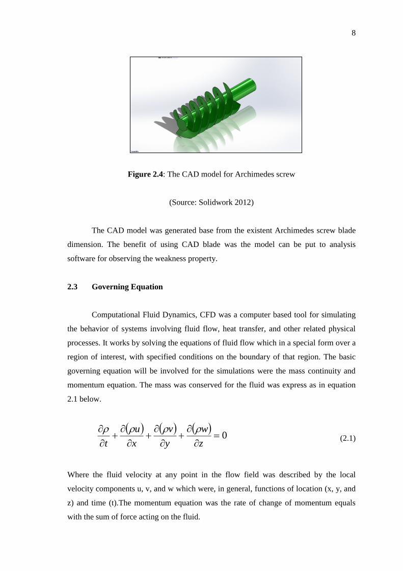
Figure 2.4: The CAD model for Archimedes screw
(Source: Solidwork 2012)
The CAD model was generated base from the existent Archimedes screw blade
dimension. The benefit of using CAD blade was the model can be put to analysis
software for observing the weakness property.
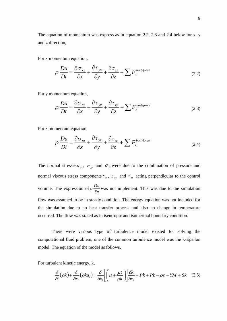
2.3 Governing Equation
Computational Fluid Dynamics, CFD was a computer based tool for simulating
the behavior of systems involving fluid flow, heat transfer, and other related physical
processes. It works by solving the equations of fluid flow which in a special form over a
region of interest, with specified conditions on the boundary of that region. The basic
governing equation will be involved for the simulations were the mass continuity and
momentum equation. The mass was conserved for the fluid was express as in equation
2.1 below.
0
z
w
y
v
x
u
t
(2.1)
Where the fluid velocity at any point in the flow field was described by the local
velocity components u, v, and w which were, in general, functions of location (x, y, and
z) and time (t).The momentum equation was the rate of change of momentum equals
with the sum of force acting on the fluid.
9
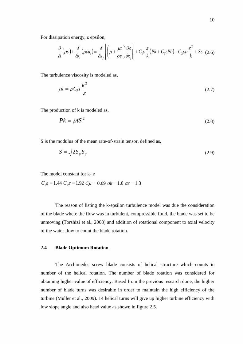
The equation of momentum was express as in equation 2.2, 2.3 and 2.4 below for x, y
and z direction,
For x momentum equation,
bodyforce
x
zxyxxx FzyxDt
Du (2.2)
For y momentum equation,
bodyforce
y
zyyyxyF
zyxDt
Du (2.3)
For z momentum equation,
bodyforce
zzzyxxz FzyxDt
Du (2.4)
The normal stresses xx , yy and zz were due to the combination of pressure and
normal viscous stress components xx , yy and zz acting perpendicular to the control
volume. The expression ofDt
Du was not implement. This was due to the simulation
flow was assumed to be in steady condition. The energy equation was not included for
the simulation due to no heat transfer process and also no change in temperature
occurred. The flow was stated as in isentropic and isothermal boundary condition.
There were various type of turbulence model existed for solving the
computational fluid problem, one of the common turbulence model was the k-Epsilon
model. The equation of the model as follows,
For turbulent kinetic energy, k,
SkYMPbPkx
k
k
t
xku
xk
t ii
i
i
(2.5)
10
For dissipation energy, ε epsilon,
S
kCPbCPk
kC
x
t
xu
xt jj
i
i
2
231 (2.6)
The turbulence viscosity is modeled as,
2kCt (2.7)
The production of k is modeled as,
2tSPk (2.8)
S is the modulus of the mean rate-of-strain tensor, defined as,
ijij SSS 2 (2.9)
The model constant for k- ε
44.11 C 92.12 C 09.0C 0.1k 3.1
The reason of listing the k-epsilon turbulence model was due the consideration
of the blade where the flow was in turbulent, compressible fluid, the blade was set to be
unmoving (Torshizi et al., 2008) and addition of rotational component to axial velocity
of the water flow to count the blade rotation.
2.4 Blade Optimum Rotation
The Archimedes screw blade consists of helical structure which counts in
number of the helical rotation. The number of blade rotation was considered for
obtaining higher value of efficiency. Based from the previous research done, the higher
number of blade turns was desirable in order to maintain the high efficiency of the
turbine (Muller et al., 2009). 14 helical turns will give up higher turbine efficiency with
low slope angle and also head value as shown in figure 2.5.

11
Figure 2.5: The theoretical efficiency as function of slope angle and number of helical
turns
(Source: Gerald Muller et al., 2009)
Thus, the blade model used for the analysis will be consisting of 14 numbers of
helical turns, slope angle and head of 2.24 meters. The fixed value was taken for
obtaining the optimum analysis result later.
2.5 Fatigue Crack
Fatigue occurrence was a general problem that usually occurs in turbine blade.
The fatigue cracks normally represent in regions that have a metallurgical or structural
discontinuity and were subjected to higher stresses (source: Flores et al., 2011). The
concept of local strains and stresses were the common approach for predicting the crack
initiation growth in a structure to fatigue loads. In the most of hydro power, the turbines
blade had been operated for decades. Due to the current operating conditions, the blade
structure was now become different from the original design specified. These operations
cause vibrations and some have presented cracks in the runners produced by fatigue.
Lots of research has been done on the fatigue crack analysis of turbine blade.
Each of the research had implemented various kind of method on identifying the crack
behavior towards the turbine especially at the runner blade. The runner blade of a

12
turbine was the most critical structure and usually expose to environment or even to the
medium which help in giving the motion to the turbine runner blade such as air, water
and etc. Most of the research done for fatigue crack analysis on hydropower was more
focus on the normal used turbine such as Francis turbine. Most of the cases studied on
the stress analysis of the turbine runner. The crack occurrence will be detected base on
the numerical method. The result obtains from simulation of Francis runner blade show
the zone with high stress was situated at the transition between the blade and the crown
on the outlet side (Source: Saeed et al., 2010). Figure 2.6 shows the appearance of
fatigue crack on the Francis turbine through experiment and also simulation.
Figure 2.6: (a) Analysis using of the Francis turbine using computer simulation (b) Real
image of the crack occurrence at the Francis turbine
(Source: R.A. Saeed et al., 2010)
Other research done on the fatigue crack analysis was based on the crack
initiation life was done by Flores et al., (2012). Based from the research, the model of
the runner was constructed to perform the modal and the static stress analysis using the
commercial software. The static stress of the runner was calculated due to the load
effect in the operational conditions cause by the centrifugal forces and the fluids static
pressure. The calculation of the dynamical stress was done for blades passing the guide
vanes. Thus, from the all the gather calculated values, the estimation of the cracking
initiation growth on the runner was obtain where the dynamical stress was maximum at
the blade near to the bend which located close to the runner exist (Source: Flores et al.,
2012). From this situation, the crack occurrence will exceed as the turbine operate at the
maximum stress condition.
(a) (b)
13
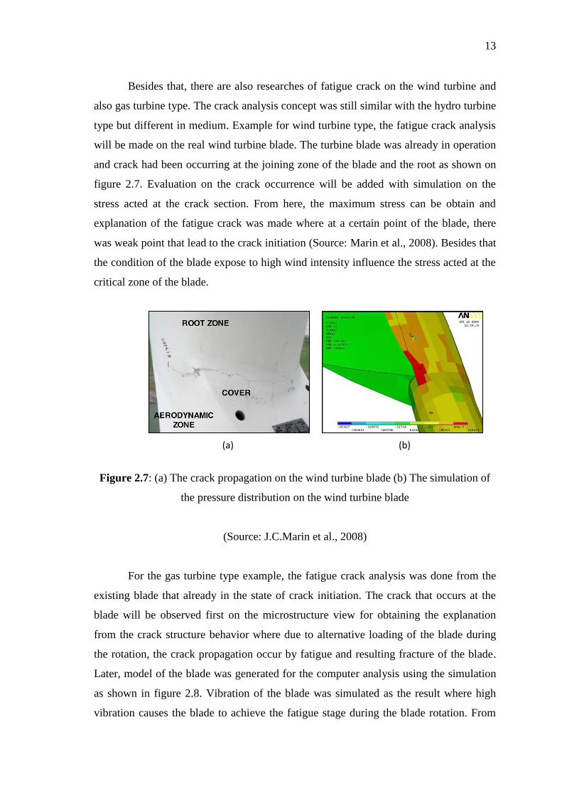
Besides that, there are also researches of fatigue crack on the wind turbine and
also gas turbine type. The crack analysis concept was still similar with the hydro turbine
type but different in medium. Example for wind turbine type, the fatigue crack analysis
will be made on the real wind turbine blade. The turbine blade was already in operation
and crack had been occurring at the joining zone of the blade and the root as shown on
figure 2.7. Evaluation on the crack occurrence will be added with simulation on the
stress acted at the crack section. From here, the maximum stress can be obtain and
explanation of the fatigue crack was made where at a certain point of the blade, there
was weak point that lead to the crack initiation (Source: Marin et al., 2008). Besides that
the condition of the blade expose to high wind intensity influence the stress acted at the
critical zone of the blade.
Figure 2.7: (a) The crack propagation on the wind turbine blade (b) The simulation of
the pressure distribution on the wind turbine blade
(Source: J.C.Marin et al., 2008)
For the gas turbine type example, the fatigue crack analysis was done from the
existing blade that already in the state of crack initiation. The crack that occurs at the
blade will be observed first on the microstructure view for obtaining the explanation
from the crack structure behavior where due to alternative loading of the blade during
the rotation, the crack propagation occur by fatigue and resulting fracture of the blade.
Later, model of the blade was generated for the computer analysis using the simulation
as shown in figure 2.8. Vibration of the blade was simulated as the result where high
vibration causes the blade to achieve the fatigue stage during the blade rotation. From
(a) (b)

14
the fatigue analysis made from the research, in resonance condition, the nominal stress
impose on the blade exceed the normal stress and this lead to exceeding of stress against
the endurance limit of the material where it can lead to failure on the blade structure
(Source: S.E. Moussavi Torshizi et.dl.2009).
Figure 2.8: (a) The microstructure of the crack initiation (b) the distribution of stress at
the gas turbine blade
(Source: S.E. Moussavi Torshizi et.dl.2009)
Even though there were lots of crack researches on turbine runner, yet there was
no research on crack had been done for the screw runner blade for micro hydro power
turbine. In this project, the analysis was more towards predicting the crack due to
erosion and sedimentation in the river bead.
(a) (b)