Embed Size (px)
Citation preview

Precision Spray Nozzles and Engineered Solutions for the Chemical Industry

2
On the one hand every company needs to develop and constantly optimize its production processes.
In automated systems, even minor discrepancies can provide optimization opportunities. On the
other side processes in the chemical industry are extremely complex and mutually dependent, each
adjustment extends far beyond its immediate scope. That’s why for over 135 years, Lechler provides
nozzle and spray technology that always involves the understanding of all the processes involved.
PrOCESS OPTImIzaTION wITh NOzzLE TEChNOLOgy
Lechler is proud of a long history in the United States
Lechler can look back on a long and successful history in the United States. In 1975 Lechler purchased the Spray Engineering Company, manufacturer of Spraco spray products. Recognizing that Spraco is and has been an established name in the spray nozzle business, Lechler continues to make many Spraco products today.
As early as when his trading company was founded in 1879, Paul Lechler believed in chemistry. Initially the main focus was on technical prod-ucts, machine oils and wood preservatives, and in 1905 the company gained exclusive sales rights to the protective coating Inertol®. By 1919 he had added his self-produced protective coatings to this portfolio. Later, our company’s focus shifted from chemical production to application and atomization of liquids. In 1961,
all chemical products were finally combined in a separate company.
But nevertheless, chemistry kept playing a major role in our company. Today Lechler offers a wide product range for the optimization of technical processes. Throughout our history, chemistry has played a major role in our compa-ny. Over the course of many decades, this gave rise to a unique understanding of spray-ing and atomization processes.
We are familiar with a wide range of applications at various pressures, temperatures and atmospheres. The following pages will provide you with several examples of this.
Company founded by Paul Lechler
Patent for liquid atomization
Expansion into the USa, followed by further countries
Sales offices set up in germany
18931879 19781962
A LECHLER COMPANY
3
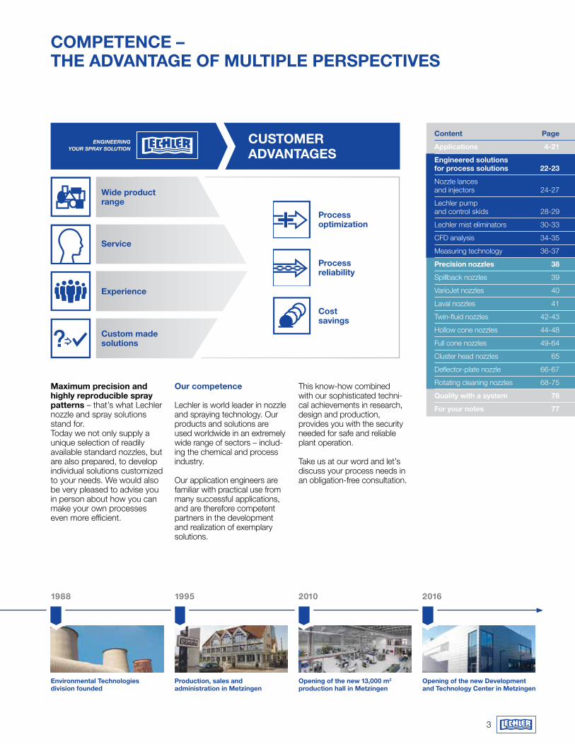
COmPETENCE – ThE advaNTagE Of mULTIPLE PErSPECTIvES
maximum precision and highly reproducible spray patterns – that’s what Lechler nozzle and spray solutions stand for. Today we not only supply a unique selection of readily available standard nozzles, but are also prepared, to develop individual solutions customized to your needs. We would also be very pleased to advise you in person about how you can make your own processes even more efficient.
Our competence
Lechler is world leader in nozzle and spraying technology. Our products and solutions are used worldwide in an extremely wide range of sectors – includ-ing the chemical and process industry.
Our application engineers are familiar with practical use from many successful applications, and are therefore competent partners in the development and realization of exemplary solutions.
This know-how combined with our sophisticat ed techni-cal achievements in research, design and produ c tion, provides you with the security needed for safe and reliable plant operation.
Take us at our word and let’s discuss your process needs in an obligation-free consultation.
Environmental Technologies division founded
Production, sales and administration in metzingen
Opening of the new 13,000 m2 production hall in metzingen
Opening of the new development and Technology Center in metzingen
2016201019951988
wide product range
Service
Experience
Custom made solutions
Process optimization
Process reliability
Cost savings
CUSTOmEr advaNTagES
Content Page
applications 4-21
Engineered solutions for process solutions 22-23
Nozzle lances and injectors 24-27
Lechler pump and control skids 28-29
Lechler mist eliminators 30-33
CFD analysis 34-35
Measuring technology 36-37
Precision nozzles 38
Spillback nozzles 39
VarioJet nozzles 40
Laval nozzles 41
Twin-fluid nozzles 42-43
Hollow cone nozzles 44-48
Full cone nozzles 49-64
Cluster head nozzles 65
Deflector-plate nozzle 66-67
Rotating cleaning nozzles 68-75
Quality with a system 76
for your notes 77

5
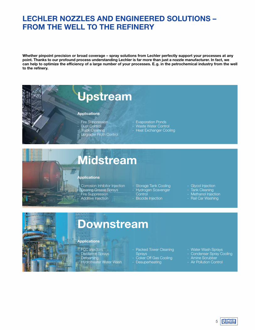
LEChLEr NOzzLES aNd ENgINEErEd SOLUTIONS – frOm ThE wELL TO ThE rEfINEry
whether pinpoint precision or broad coverage – spray solutions from Lechler perfectly support your processes at any point. Thanks to our profound process understanding Lechler is far more than just a nozzle manufacturer. In fact, we can help to optimize the efficiency of a large number of your processes. E. g. in the petrochemical industry from the well to the refinery.
applications
- Fire Suppression - Dust Control - Truck Cleaning - Upgrader Froth Control
applications
- Corrosion Inhibitor Injection - Bearing Grease Sprays - Fire Suppression - Additive Injection
applications
- FCC Injectors - Distillation Sprays - Defoaming - Hydrotreater Water Wash
Upstream
midstream
downstream
- Evaporation Ponds - Waste Water Control - Heat Exchanger Cooling
- Storage Tank Cooling - Hydrogen Scavenger
Control - Biocide Injection
- Packed Tower Cleaning Sprays
- Coker Off Gas Cooling - Desuperheating
- Glycol Injection - Tank Cleaning - Methanol Injection - Rail Car Washing
- Water Wash Sprays - Condenser Spray Cooling - Amine Scrubber - Air Pollution Control


7
applications
- Heat Exchanger Sprays - Desuperheating - Rapid Quenching Sprays - Plastic Fiber Cooling
applications
- Tank Cleaning - Heat Exchanger Sprays - Carbon Products
Manufacturing
applications
- SO2 Reduction - Circulating Dry Scrubber
- Wet FGD- Spray Dry Absorbers
Basic Chemicals
Specialty Chemicals
air Pollution Control
- Granulation - Pelletizer - Fractionation
- Spray Drying - Rapid Quenching Sprays - Granulation - Fire Protection
- Gas Cooling Upstream of Baghouses and ESP’s
- Wet Scrubbers
- Pelletizer - Sulfuric Acid Regeneration - Fuel Oil Spray - Fractionation
- NOx Reduction - SCR - SNCR
Intense heat, high pressure, corrosive agents – every aspect of our nozzles has to be well defined right from the beginning in order to maintain the ultimate precision. This begins with the internal dimensions and doesn’t end at the choice of the material. after the design phase every nozzle is rigorously examined in our test facilities. This way, we can ensure that the spray patterns of our nozzles match perfectly with the needs of your processes.
LEChLEr NOzzLES aNd ENgINEErEd SOLUTIONS – aT hOmE aLONg ThE ENTIrE PrOCESS LINE

8
Engineered Solutions for Process applications
Precision Spray Nozzles
The variety of different products synthesized and processed by the chemical industry is enormous. The same is true for the involved processes. most of them are widely used and well understood. Others were specially developed and require extreme ambient conditions, occasionally customized to single reaction vessels.
Lechler supplies you in both areas with state-of-the-art nozzles and spray technologies.
ThIS IS whErE yOU fINd yOUr aNSwEr

9
� Customized products and solutions
� Tailored to your needs � Extensive consultation � Individual design and process support
For large industry framework conditions special engineered solutions are necessary. That’s why we also present to you additional Lechler customized products and solutions that we make only to order to meet the special needs of the chemical and petrochemical industry, e.g. pump and control skid units, lances, special nozzles, gas cooling and conditioning systems, mist eliminators and more. If you can‘t find what you’re looking for, don’t hesitate to contact us.
We would be happy to examine the possibilities available to us for developing the optimum atomization nozzle to suit your needs – custom made and in close collaboration with you. Please note the production related delivery times and costs for the nozzles presented here.
For most applications, our precision spray nozzles will provide excellent results.
These parts have not only been meticulously designed but also have stood the test of time. Thanks to large-volume production, they are readily available at a reasonable price for the various applications in chemical-related applications. In this brochure you’ll find our most commonly used products.
� Thousands of standardized nozzles
� Tried and tested � Great value for money � Short delivery time
Pre
cisi
on
Sp
ray
Noz
zles
E
ngin
eere
d S
olu
tions
10
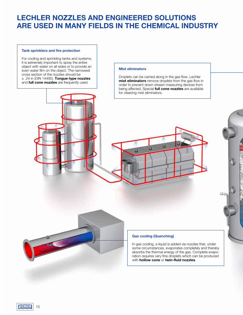
LEChLEr NOzzLES aNd ENgINEErEd SOLUTIONS arE USEd IN maNy fIELdS IN ThE ChEmICaL INdUSTry
Tank sprinklers and fire protection
For cooling and sprinkling tanks and systems, it is extremely important to spray the entire object with water on all sides or to provide an even water film on the object. The narrowest cross section of the nozzles should be ≥ .24 in (DIN 14495). Tongue-type nozzles and full cone nozzles are frequently used.
mist eliminators
Droplets can be carried along in the gas flow. Lechler mist eliminators remove droplets from the gas flow in order to prevent down-stream measuring devices from being affected. Special full cone nozzles are available for cleaning mist eliminators.
gas cooling (Quenching)
In gas cooling, a liquid is added via nozzles that, under some circumstances, evaporates completely and there by absorbs the thermal energy of the gas. Complete evapo- ration requires very fine droplets which can be produced with hollow cone or twin-fluid nozzles.
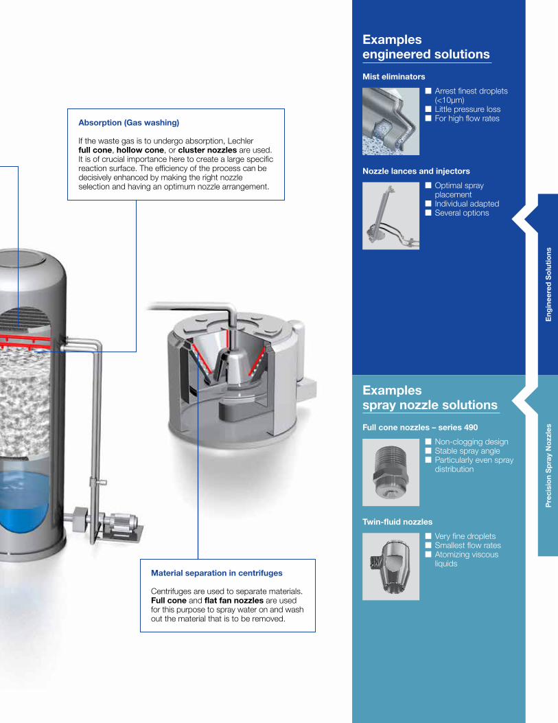
absorption (gas washing)
If the waste gas is to undergo absorption, Lechler full cone, hollow cone, or cluster nozzles are used. It is of crucial importance here to create a large specific reaction surface. The efficiency of the process can be decisively enhanced by making the right nozzle selection and having an optimum nozzle arrangement.
material separation in centrifuges
Centrifuges are used to separate materials. full cone and flat fan nozzles are used for this purpose to spray water on and wash out the material that is to be removed.
Eng
inee
red
So
lutio
ns
Examples engineered solutions
Examples spray nozzle solutions
full cone nozzles – series 490
� Non-clogging design � Stable spray angle � Particularly even spray distribution
mist eliminators
� Arrest finest droplets (<10µm)
� Little pressure loss � For high flow rates
Nozzle lances and injectors
� Optimal spray placement
� Individual adapted � Several options
Twin-fluid nozzles
� Very fine droplets � Smallest flow rates � Atomizing viscous liquids
Pre
cisi
on
Sp
ray
Noz
zles
12
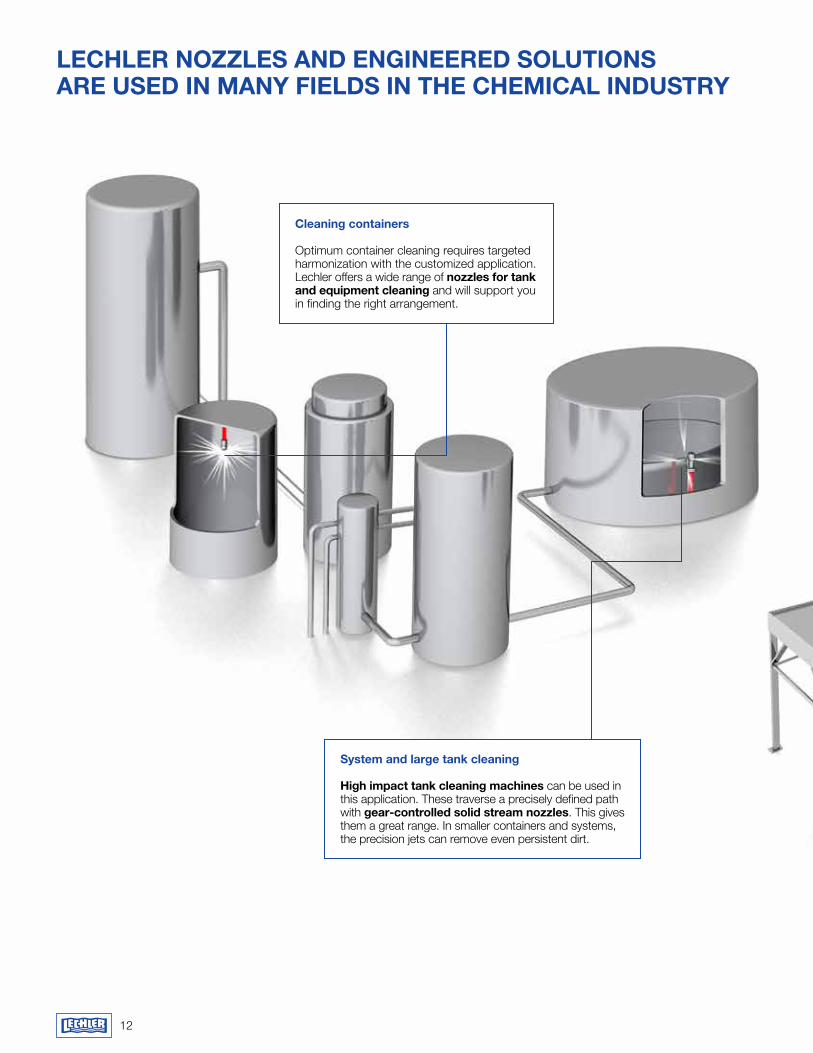
Cleaning containers
Optimum container cleaning requires targeted harmonization with the customized application. Lechler offers a wide range of nozzles for tank and equipment cleaning and will support you in finding the right arrangement.
System and large tank cleaning
high impact tank cleaning machines can be used in this application. These traverse a precisely defined path with gear-controlled solid stream nozzles. This gives them a great range. In smaller containers and systems, the precision jets can remove even persistent dirt.
LEChLEr NOzzLES aNd ENgINEErEd SOLUTIONS arE USEd IN maNy fIELdS IN ThE ChEmICaL INdUSTry
Examples engineered solutions
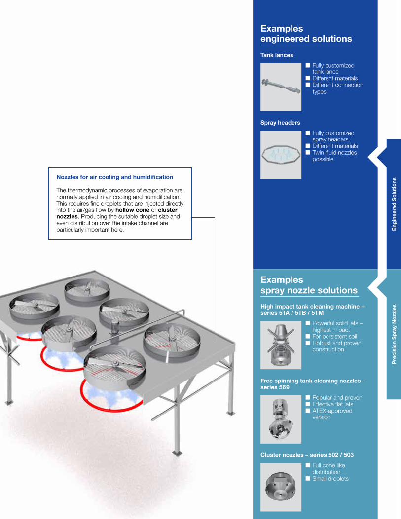
Tank lances
� Fully customized tank lance
� Different materials � Different connection types
Spray headers
� Fully customized spray headers
� Different materials � Twin-fluid nozzles possible
Nozzles for air cooling and humidification
The thermodynamic processes of evaporation are normally applied in air cooling and humidification. This requires fine droplets that are injected directly into the air/gas flow by hollow cone or cluster nozzles. Producing the suitable droplet size and even distribution over the intake channel are particularly important here.
high impact tank cleaning machine – series 5Ta / 5TB / 5Tm
� Powerful solid jets – highest impact
� For persistent soil � Robust and proven construction
free spinning tank cleaning nozzles – series 569
� Popular and proven � Effective flat jets � ATEX-approved version
Cluster nozzles – series 502 / 503
� Full cone like distribution
� Small droplets
Examples spray nozzle solutions
Eng
inee
red
So
lutio
nsP
reci
sio
n S
pra
y N
ozzl
es
14
LEChLEr NOzzLES aNd ENgINEErEd SOLUTIONS arE USEd IN maNy fIELdS IN ThE ChEmICaL INdUSTry
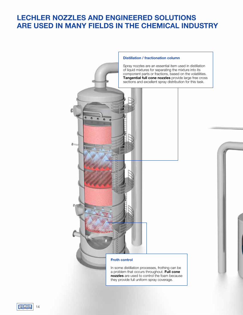
distillation / fractionation column
Spray nozzles are an essential item used in distillation of liquid mixtures for separating the mixture into its component parts or fractions, based on the volatilities. Tangential full cone nozzles provide large free cross sections and excellent spray distribution for this task.
froth control
In some distillation processes, frothing can be a problem that occurs throughout. full cone nozzles are used to control the foam because they provide full uniform spray coverage.
Eng
inee
red
So
lutio
ns
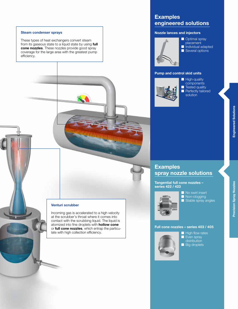
Steam condenser sprays
These types of heat exchangers convert steam from its gaseous state to a liquid state by using full cone nozzles. These nozzles provide good spray coverage for the large area with the greatest pump efficiency.
venturi scrubber
Incoming gas is accelerated to a high velocity at the scrubber’s throat where it comes into contact with the scrubbing liquid. The liquid is atomized into fine droplets with hollow cone or full cone nozzles, which entrap the particu-late with high collection efficiency.
Examples engineered solutions
Pump and control skid units
� High-quality components
� Tested quality � Perfectly tailored solution
Nozzle lances and injectors
� Optimal spray placement
� Individual adapted � Several options
full cone nozzles – series 403 / 405
� High flow rates � Even spray distribution
� Big droplets
Examples spray nozzle solutions
Tangential full cone nozzles – series 422 / 423
� No swirl insert � Non-clogging � Stable spray angles
Pre
cisi
on
Sp
ray
Noz
zles
16
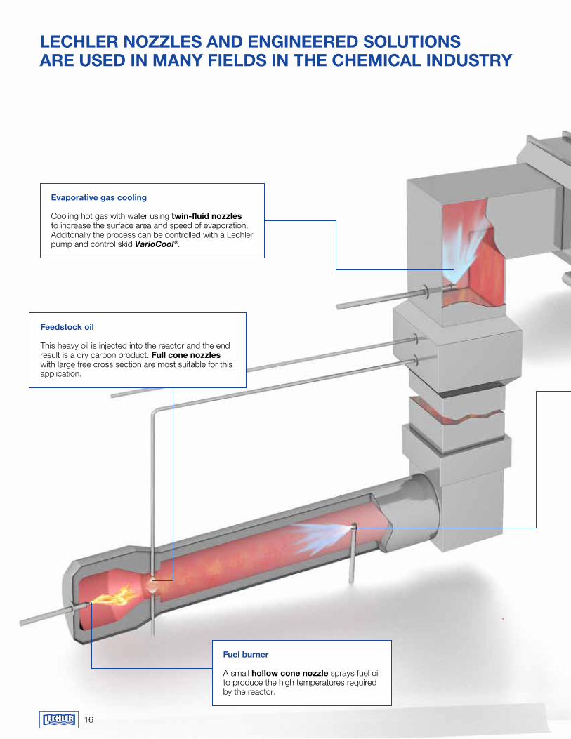
Evaporative gas cooling
Cooling hot gas with water using twin-fluid nozzles to increase the surface area and speed of evaporation. Additonally the process can be controlled with a Lechler pump and control skid VarioCool®.
feedstock oil
This heavy oil is injected into the reactor and the end result is a dry carbon product. full cone nozzles with large free cross section are most suitable for this application.
fuel burner
A small hollow cone nozzle sprays fuel oil to produce the high temperatures required by the reactor.
LEChLEr NOzzLES aNd ENgINEErEd SOLUTIONS arE USEd IN maNy fIELdS IN ThE ChEmICaL INdUSTry
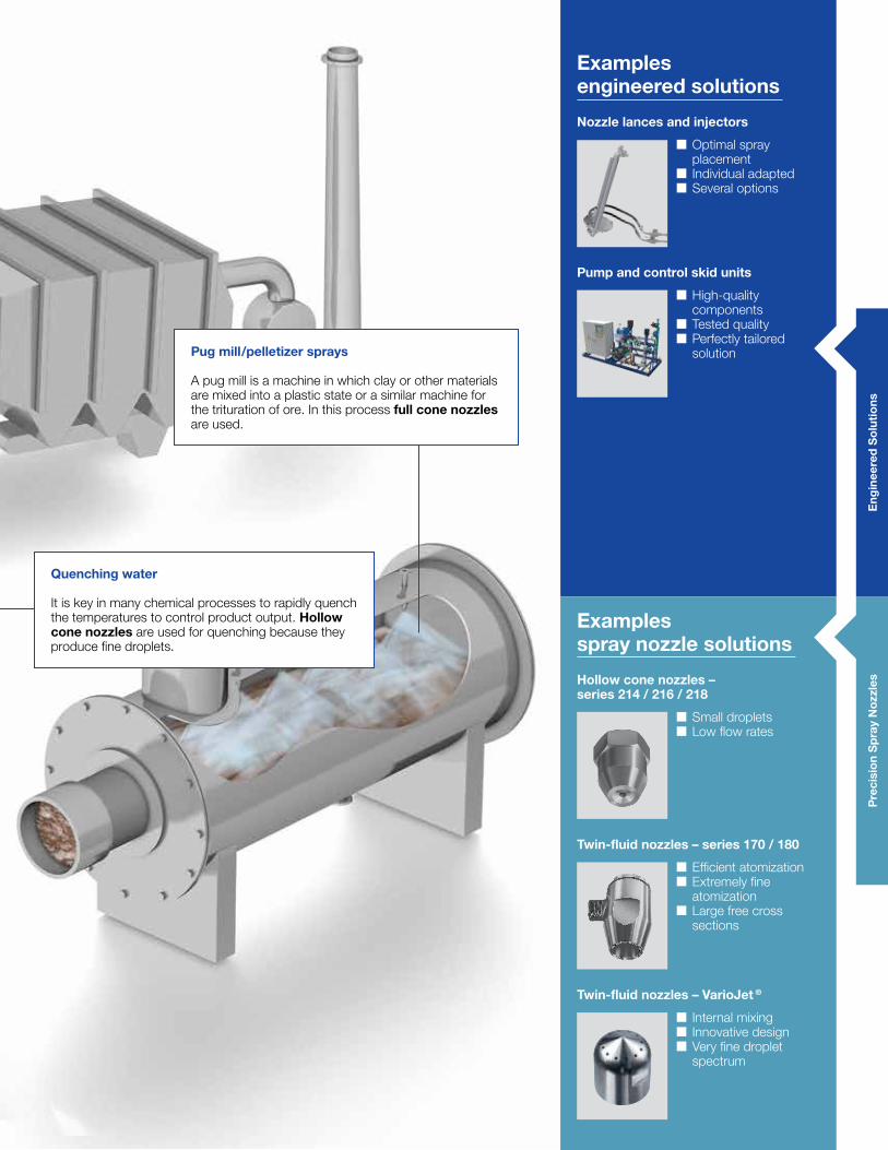
Quenching water
It is key in many chemical processes to rapidly quench the temperatures to control product output. hollow cone nozzles are used for quenching because they produce fine droplets.
Pug mill/pelletizer sprays
A pug mill is a machine in which clay or other materials are mixed into a plastic state or a similar machine for the trituration of ore. In this process full cone nozzles are used.
Eng
inee
red
So
lutio
ns
Examples engineered solutions
Nozzle lances and injectors
� Optimal spray placement
� Individual adapted � Several options
Twin-fluid nozzles – series 170 / 180
� Efficient atomization � Extremely fine atomization
� Large free cross sections
Twin-fluid nozzles – VarioJet ®
� Internal mixing � Innovative design � Very fine droplet spectrum
Examples spray nozzle solutions
hollow cone nozzles – series 214 / 216 / 218
� Small droplets � Low flow rates
Pump and control skid units
� High-quality components
� Tested quality � Perfectly tailored solution
Pre
cisi
on
Sp
ray
Noz
zles
18
LEChLEr NOzzLES aNd ENgINEErEd SOLUTIONS arE USEd IN maNy fIELdS IN ThE ChEmICaL INdUSTry
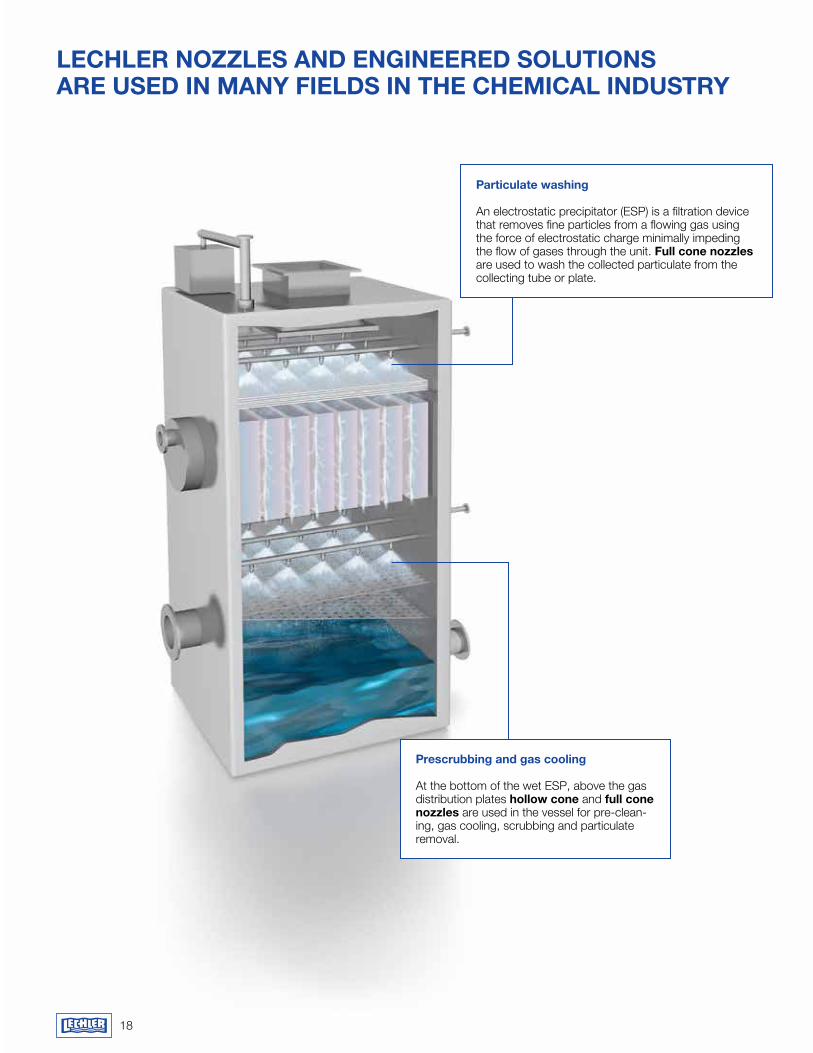
Particulate washing
An electrostatic precipitator (ESP) is a filtration device that removes fine particles from a flowing gas using the force of electrostatic charge minimally impeding the flow of gases through the unit. full cone nozzles are used to wash the collected particulate from the collecting tube or plate.
Prescrubbing and gas cooling
At the bottom of the wet ESP, above the gas distribution plates hollow cone and full cone nozzles are used in the vessel for pre-clean-ing, gas cooling, scrubbing and particulate removal.
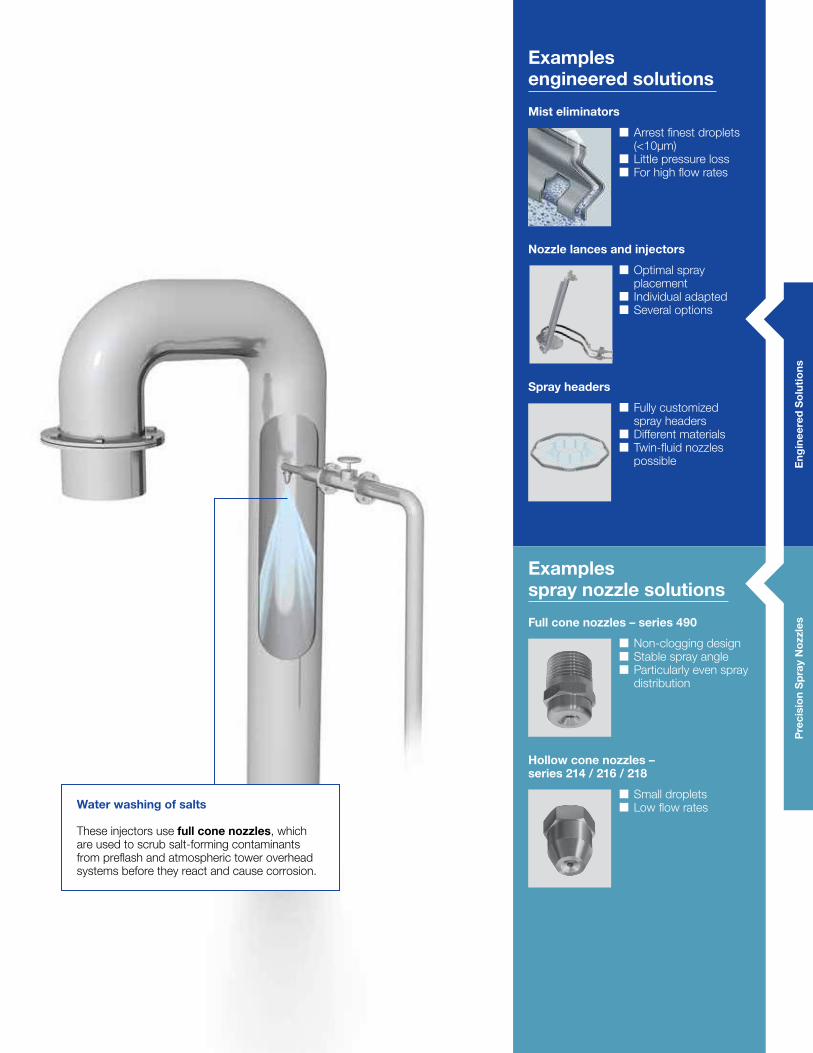
water washing of salts
These injectors use full cone nozzles, which are used to scrub salt-forming contaminants from preflash and atmospheric tower overhead systems before they react and cause corrosion.
Eng
inee
red
So
lutio
nsP
reci
sio
n S
pra
y N
ozzl
es
Examples engineered solutions
mist eliminators
� Arrest finest droplets (<10µm)
� Little pressure loss � For high flow rates
Nozzle lances and injectors
� Optimal spray placement
� Individual adapted � Several options
Spray headers
� Fully customized spray headers
� Different materials � Twin-fluid nozzles possible
full cone nozzles – series 490
� Non-clogging design � Stable spray angle � Particularly even spray distribution
Examples spray nozzle solutions
hollow cone nozzles – series 214 / 216 / 218
� Small droplets � Low flow rates
20
LEChLEr NOzzLES aNd ENgINEErEd SOLUTIONS arE USEd IN maNy fIELdS IN ThE ChEmICaL INdUSTry
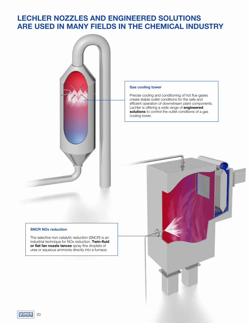
gas cooling tower
Precise cooling and conditioning of hot flue gases create stable outlet conditions for the safe and efficient operation of downstream plant components. Lechler is offering a wide range of engineered solutions to control the outlet conditions of a gas cooling tower.
SNCr NOx reduction
The selective non-catalytic reduction (SNCR) is an industrial technique for NOx reduction. Twin-fluid or flat fan nozzle lances spray fine droplets of urea or aqueous ammonia directly into a furnace.
Pre
cisi
on
Sp
ray
Noz
zles
E
ngin
eere
d S
olu
tions
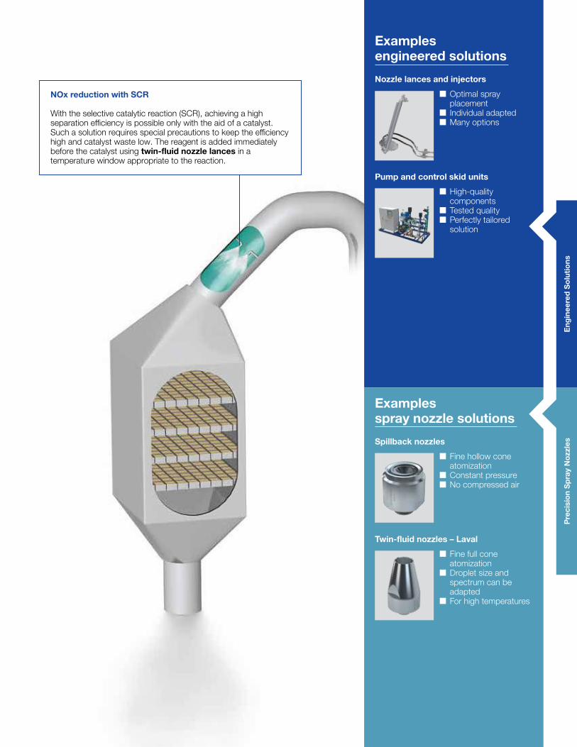
NOx reduction with SCr
With the selective catalytic reaction (SCR), achieving a high separation efficiency is possible only with the aid of a catalyst. Such a solution requires special precautions to keep the efficiency high and catalyst waste low. The reagent is added immediately before the catalyst using twin-fluid nozzle lances in a temperature window appropriate to the reaction.
Examples engineered solutions
Nozzle lances and injectors
� Optimal spray placement
� Individual adapted � Many options
Pump and control skid units
� High-quality components
� Tested quality � Perfectly tailored solution
Spillback nozzles
� Fine hollow cone atomization
� Constant pressure � No compressed air
Examples spray nozzle solutions
Twin-fluid nozzles – Laval
� Fine full cone atomization
� Droplet size and spectrum can be adapted
� For high temperatures

23
Eng
inee
red
So
lutio
ns
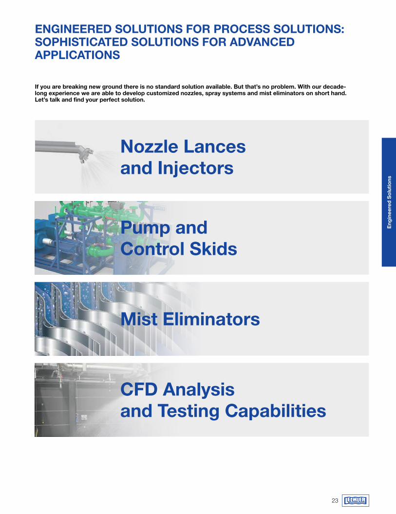
ENgINEErEd SOLUTIONS fOr PrOCESS SOLUTIONS: SOPhISTICaTEd SOLUTIONS fOr advaNCEd aPPLICaTIONS
If you are breaking new ground there is no standard solution available. But that’s no problem. with our decade- long experience we are able to develop customized nozzles, spray systems and mist eliminators on short hand. Let’s talk and find your perfect solution.
Nozzle Lances and Injectors
Pump and Control Skids
mist Eliminators
Cfd analysis and Testing Capabilities
24
Eng
inee
red
So
lutio
ns
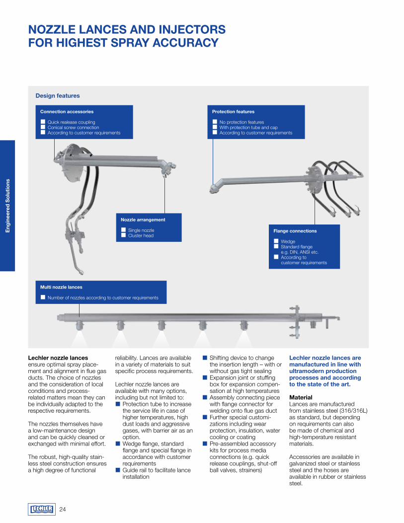
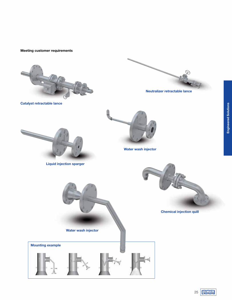
Lechler nozzle lances ensure optimal spray place-ment and alignment in flue gas ducts. The choice of nozzles and the conside ration of local conditions and process- related matters mean they can be individually adapted to the respective requirements.
The nozzles themselves have a low-maintenance design and can be quickly cleaned or exchanged with minimal effort.
The robust, high-quality stain-less steel construction ensures a high degree of functional
reliability. Lances are available in a variety of materials to suit specific process requirements.
Lechler nozzle lances are available with many options, including but not limited to:�� Protection tube to increase the service life in case of higher temperatures, high dust loads and aggressive gases, with barrier air as an option.�� Wedge flange, standard flange and special flange in accordance with customer requirements�� Guide rail to facilitate lance installation
�� Shifting device to change the insertion length – with or without gas tight sealing�� Expansion joint or stuffing box for expansion compen-sation at high temperatures�� Assembly connecting piece with flange connector for welding onto flue gas duct�� Further special customi-zations including wear protection, insulation, water cooling or coating�� Pre-assembled accessory kits for process media connections (e.g. quick release couplings, shut-off ball valves, strainers)
Lechler nozzle lances are manufactured in line with ultramodern production processes and according to the state of the art.
materialLances are manufactured from stainless steel (316/316L) as standard, but depending on requirements can also be made of chemical and high-temperature resistant materials.
Accessories are available in galvanized steel or stainless steel and the hoses are available in rubber or stainless steel.
design features
NozzLE LaNcES aNd INJEcTorS fOr hIghEST SPray aCCUraCy
Connection accessories
�� Quick realease coupling�� Conical screw connection�� According to customer requirements
Protection features
�� No protection features�� With protection tube and cap �� According to customer requirements
flange connections
�� Wedge�� Standard flange e.g. DIN, ANSI etc.�� According to customer requirements
Nozzle arrangement
�� Single nozzle�� Cluster head
multi nozzle lances
�� Number of nozzles according to customer requirements
25
Eng
inee
red
So
lutio
ns
Neutralizer retractable lance
water wash injector
Chemical injection quill
Liquid injection sparger
Catalyst retractable lance
water wash injector
meeting customer requirements
mounting example
26
Eng
inee
red
So
lutio
ns
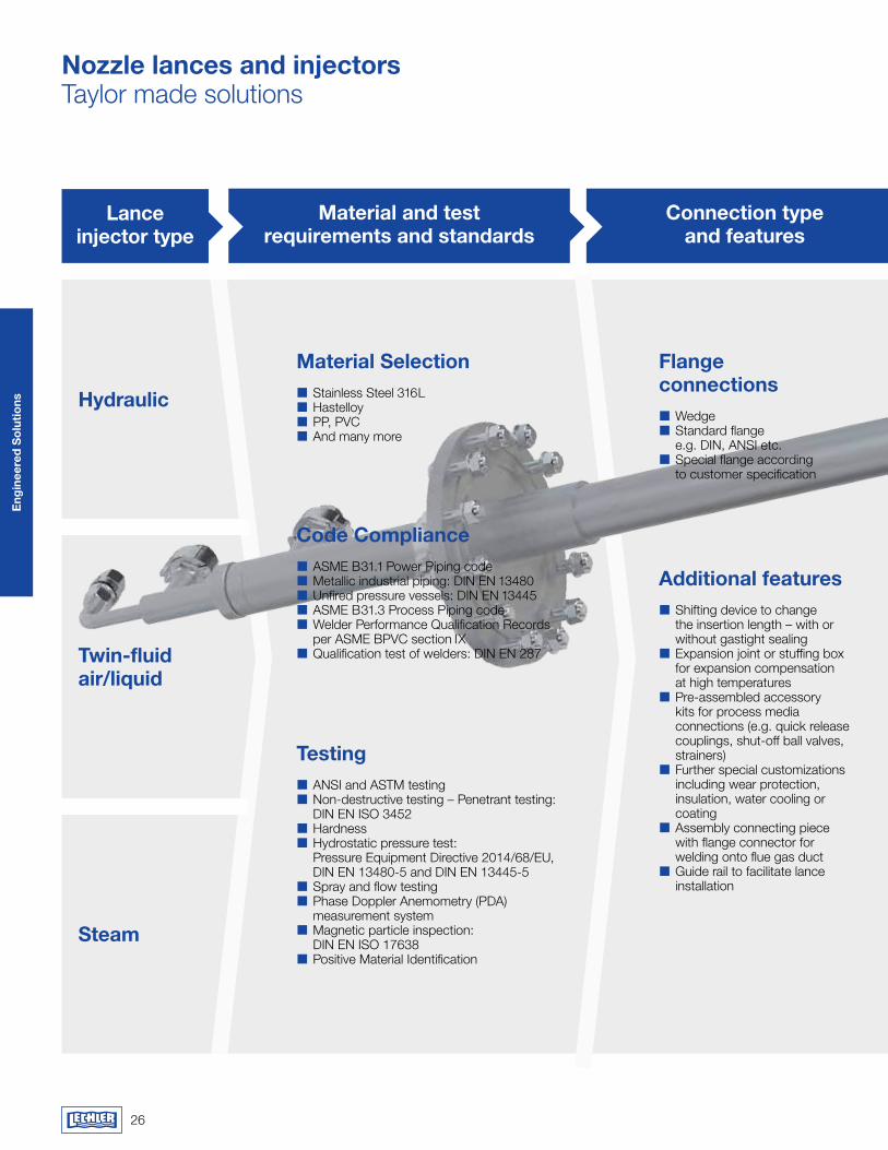
Nozzle lances and injectorsTaylor made solutions
Twin-fluid air/liquid
Steam
Code Compliance�� ASME B31.1 Power Piping code�� Metallic industrial piping: DIN EN 13480�� Unfired pressure vessels: DIN EN 13445�� ASME B31.3 Process Piping code�� Welder Performance Qualification Records per ASME BPVC section IX�� Qualification test of welders: DIN EN 287
Testing�� ANSI and ASTM testing�� Non-destructive testing – Penetrant testing: DIN EN ISO 3452�� Hardness�� Hydrostatic pressure test: Pressure Equipment Directive 2014/68/EU, DIN EN 13480-5 and DIN EN 13445-5�� Spray and flow testing�� Phase Doppler Anemometry (PDA) measurement system�� Magnetic particle inspection: DIN EN ISO 17638�� Positive Material Identification
additional features�� Shifting device to change the insertion length – with or without gastight sealing�� Expansion joint or stuffing box for expansion compensation at high temperatures�� Pre-assembled accessory kits for process media connections (e.g. quick release couplings, shut-off ball valves, strainers)�� Further special customi zations including wear protection, insulation, water cooling or coating�� Assembly connecting piece with flange connector for welding onto flue gas duct�� Guide rail to facilitate lance installation
material and test requirements and standards
Connection type and features
hydraulic
flange connections�� Wedge�� Standard flange e.g. DIN, ANSI etc.�� Special flange according to customer specification
Lance injector type
material Selection�� Stainless Steel 316L�� Hastelloy�� PP, PVC�� And many more
27
Eng
inee
red
So
lutio
ns
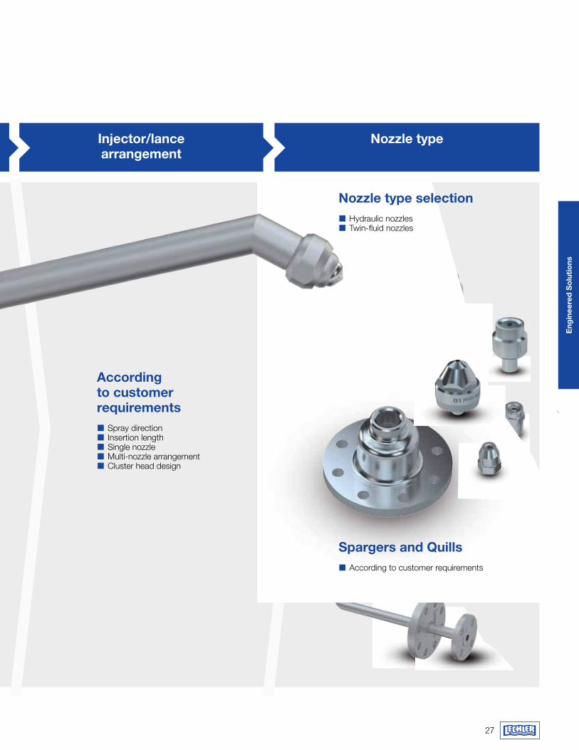
Nozzle type
according to customer requirements�� Spray direction�� Insertion length�� Single nozzle�� Multi-nozzle arrangement�� Cluster head design
Connection type and features
Injector/lance arrangement
Nozzle type selection�� Hydraulic nozzles�� Twin-fluid nozzles
Spargers and Quills�� According to customer requirements
28
Eng
inee
red
So
lutio
ns
PUmP aNd CONTrOL SkIdS a PErfECTLy TaILOrEd SOLUTION
high-quality componentsAn exact knowledge of the characteristic properties of our nozzles is key here. Only a complete system that is coordinated to how the nozzles function and operate will ensure smooth and economical operation of the gas cooling system. Unexpected failures can quickly lead to plant stoppages and costly production outages. This is why we fit our pump and control skid units with high-quality components from well-known manufacturers as standard and the most important functional components are even realized in redundant design.
The components are interconnected with pipes and mounted on a stable base frame with eyelets for crane transportation, at the same time ensuring that all components for operation and maintenance are arranged in an easily accessible manner.
Tested qualityThe design (e.g. dimensioning of nominal widths) and production are in line with the latest state of the art and comply with all relevant standards. They are equally subject to the Lechler quality management system certified to DIN EN ISO 9001, as is the final acceptance. Before delivery, the pump and control skid unit undergoes a pressure and tightness test and is checked by our experienced engineers. This will avoid any problems during commissioning.
Control concept from the nozzle specialistNumerous installations of VarioCool® systems, years of commissioning experience, plus expertise in nozzle techno logy all con-tribute to the constant improvement and optimization of Lechler control systems. By installing a control solution from Lechler you will benefit considerably from this wealth of experience. The flexible and fully automatic concept can be perfectly adapted to your process. You will have start-up and shut-down scenarios and dynamic process conditions under perfect control with our solution.
first-class engineeringTo perform our engineering, we determine all relevant parameters and define the plant’s design. This includes determining the nominal widths and pressure levels as well as designing the pumps and control valves. We draw up the P&I diagram and make detailed equipment and signal lists as an option. Of course, the project is fully documented to ensure that technology and pro-cesses can be quickly traced even after years of use.
our pump and control skid units for regulating the flow rates of water and atomizing air are individual customer- specific solutions. Based on the requirements in each case, our first step is to design an overall concept and select the best components in order to create a perfectly tailored solution.
29
Eng
inee
red
So
lutio
ns
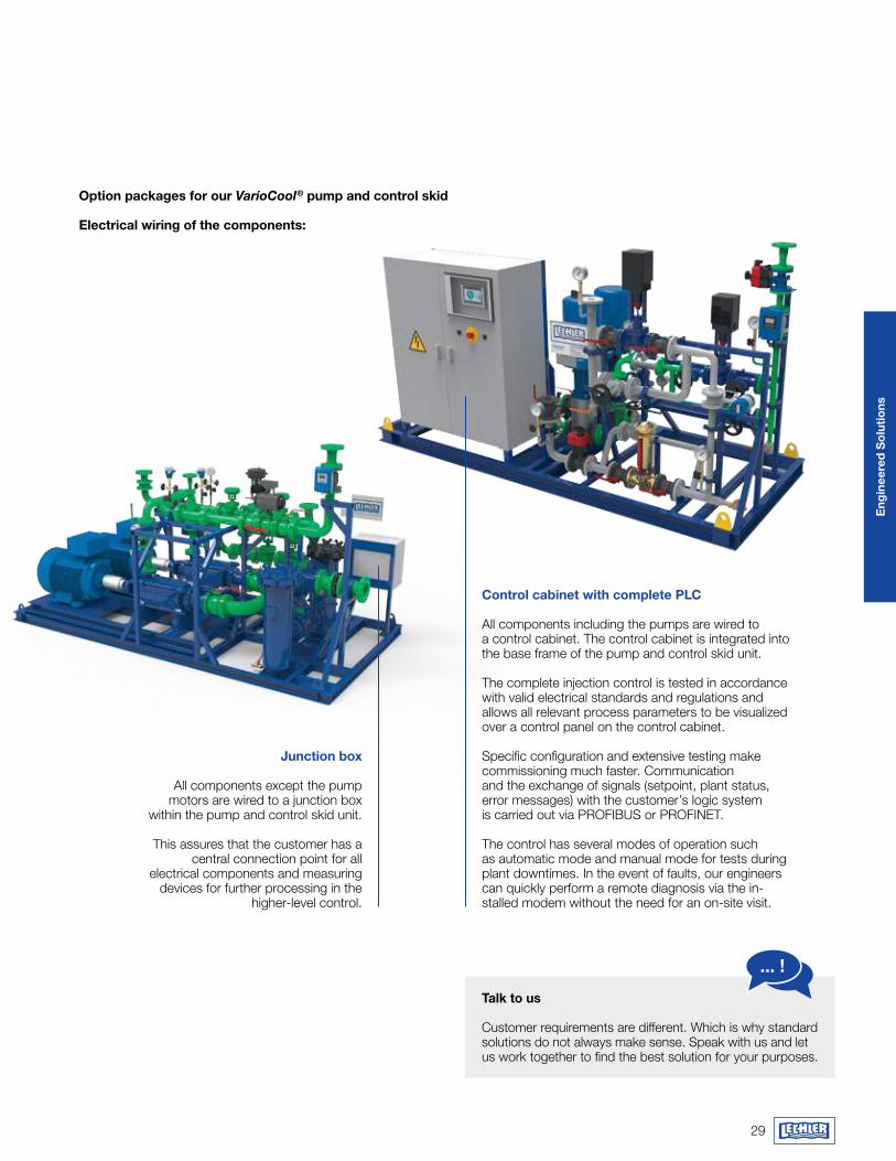
Option packages for our VarioCool® pump and control skid Electrical wiring of the components:
Talk to us
Customer requirements are different. Which is why standard solutions do not always make sense. Speak with us and let us work together to find the best solution for your purposes.
... !
Junction box
All components except the pump motors are wired to a junction box
within the pump and control skid unit.
This assures that the customer has a central connection point for all
electrical components and measuring devices for further processing in the
higher-level control.
Control cabinet with complete PLC
All components including the pumps are wired to a control cabinet. The control cabinet is integrated into the base frame of the pump and control skid unit. The complete injection control is tested in accordance with valid electrical standards and regulations and allows all relevant process parameters to be visualized over a control panel on the control cabinet. Specific configuration and extensive testing make commissioning much faster. Communication and the exchange of signals (setpoint, plant status, error messages) with the customer’s logic system is carried out via PROFIBUS or PROFINET.
The control has several modes of operation such as automatic mode and manual mode for tests during plant downtimes. In the event of faults, our engineers can quickly perform a remote diagnosis via the in-stalled modem without the need for an on-site visit.
30
Eng
inee
red
So
lutio
ns
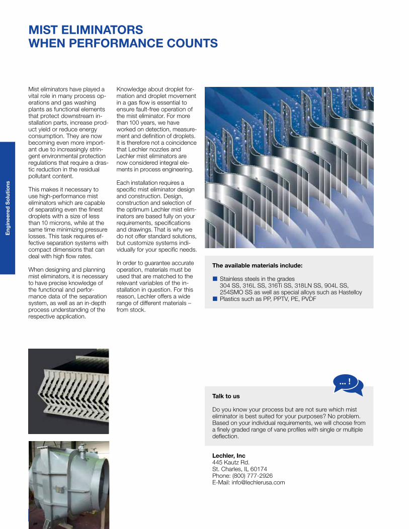
mIST ELImINaTOrS whEN PErfOrmaNCE COUNTS
Lechler, Inc445 Kautz Rd.St. Charles, IL 60174Phone: (800) 777-2926E-Mail: [email protected]
Mist eliminators have played a vital role in many process op-erations and gas washing plants as functional elements that protect downstream in-stallation parts, increase prod-uct yield or reduce energy consumption. They are now becoming even more import-ant due to increasingly strin-gent environmental protection regulations that require a dras-tic reduction in the re sidual pollutant content.
This makes it necessary to use high-performance mist eliminators which are capable of separating even the finest droplets with a size of less than 10 microns, while at the same time minimizing pressure losses. This task requires ef-fective separation systems with compact dimensions that can deal with high flow rates.
When designing and planning mist eliminators, it is necessary to have precise knowledge of the functional and perfor-mance data of the separation system, as well as an in-depth process understanding of the respective application.
Knowledge about droplet for-mation and droplet movement in a gas flow is essential to ensure fault-free operation of the mist eliminator. For more than 100 years, we have worked on detection, measure-ment and definition of droplets. It is therefore not a coincidence that Lechler nozzles and Lechler mist eliminators are now considered integral ele-ments in process engineering.
Each installation requires a specific mist eliminator design and construction. Design, construction and selection of the optimum Lechler mist elim-inators are based fully on your requirements, specifications and drawings. That is why we do not offer standard solutions, but customize systems indi-vidually for your specific needs.
In order to guarantee accurate operation, materials must be used that are matched to the relevant variables of the in-stallation in question. For this reason, Lechler offers a wide range of different materials – from stock.
Talk to us
Do you know your process but are not sure which mist eliminator is best suited for your purposes? No problem. Based on your individual requirements, we will choose from a finely graded range of vane profiles with single or multiple deflection.
... !
The available materials include:
�� Stainless steels in the grades 304 SS, 316L SS, 316Ti SS, 318LN SS, 904L SS, 254SMO SS as well as special alloys such as Hastelloy�� Plastics such as PP, PPTV, PE, PVDF
31
Eng
inee
red
So
lutio
ns
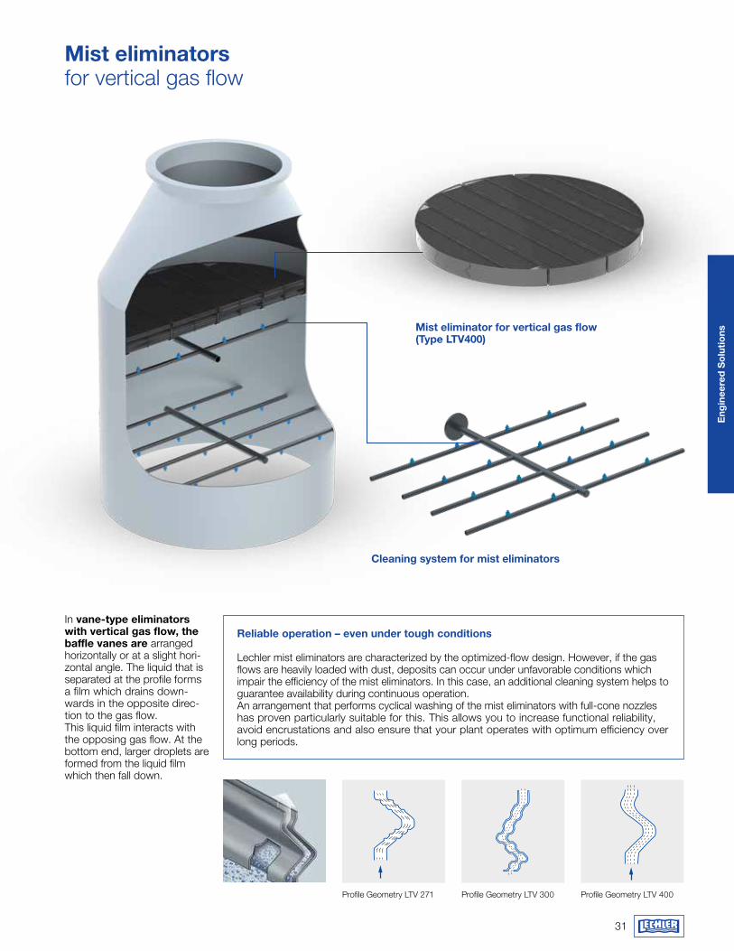
mist eliminators for vertical gas flow
reliable operation – even under tough conditions
Lechler mist eliminators are characterized by the optimized-flow design. However, if the gas flows are heavily loaded with dust, deposits can occur under unfavorable conditions which impair the efficiency of the mist eliminators. In this case, an additional cleaning system helps to guarantee availability during continuous operation. An arrangement that performs cyclical washing of the mist eliminators with full-cone nozzles has proven particularly suitable for this. This allows you to increase functional reliability, avoid encrustations and also ensure that your plant operates with optimum efficiency over long periods.
In vane-type eliminators with vertical gas flow, the baffle vanes are arranged horizontally or at a slight hori-zontal angle. The liquid that is separated at the profile forms a film which drains down-wards in the opposite direc-tion to the gas flow. This liquid film interacts with the opposing gas flow. At the bottom end, larger droplets are formed from the liquid film which then fall down.
Profile Geometry LTV 271 Profile Geometry LTV 300 Profile Geometry LTV 400
Mist eliminator for vertical gas flow (Type LTv400)
Cleaning system for mist eliminators
32
Eng
inee
red
So
lutio
ns
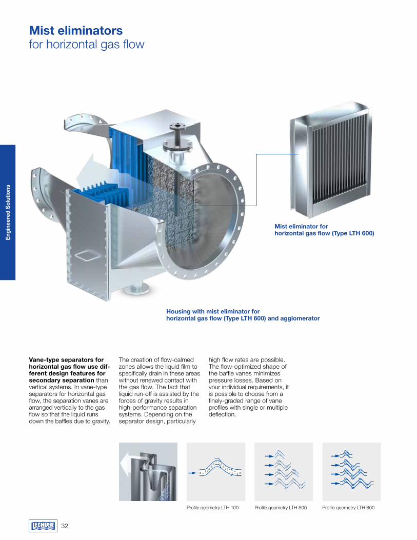
mist eliminators for horizontal gas flow
vane-type separators for horizontal gas flow use dif-ferent design features for secondary separation than vertical systems. In vane-type separators for horizontal gas flow, the separation vanes are arranged vertically to the gas flow so that the liquid runs down the baffles due to gravity.
The creation of flow-calmed zones allows the liquid film to specifically drain in these areas without renewed contact with the gas flow. The fact that liquid run-off is assisted by the forces of gravity results in high-performance separation systems. Depending on the separator design, particularly
high flow rates are possible. The flow-optimized shape of the baffle vanes minimizes pressure losses. Based on your individual requirements, it is possible to choose from a finely-graded range of vane profiles with single or multiple deflection.
housing with mist eliminator for horizontal gas flow (Type LTH 600) and agglomerator
mist eliminator for horizontal gas flow (Type LTH 600)
Profile geometry LTH 100 Profile geometry LTH 500 Profile geometry LTH 600
33
Eng
inee
red
So
lutio
ns
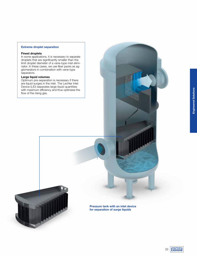
Pressure tank with an inlet device for separation of surge liquids
Extreme droplet separation
finest dropletsIn some applications, it is necessary to separate droplets that are significantly smaller than the limit droplet diameter of a vane-type mist elimi-nator. In these cases, we use fiber packs as ag-glomerators in combination with vane-type separators. Large liquid volumesOptimum pre-separation is necessary if there are liquid surges in the inlet. The Lechler Inlet Device (LID) separates large liquid quantities with maximum efficiency and thus optimizes the flow of the rising gas.
Eng
inee
red
So
lutio
ns
35
Eng
inee
red
So
lutio
ns
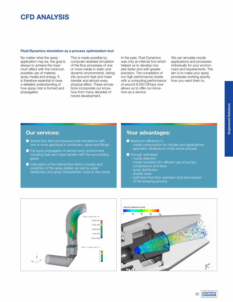
Our services: � Simple flow field and pressure loss simulations with one or more gas/liquid in containers, pipes and fittings
� Full spray propagation in almost every environment including heat and mass transfer with the surrounding gases
� Calculation of the internal flow field in nozzles and prediction of the spray pattern as well as water distribution and spray characteristic close to the nozzle
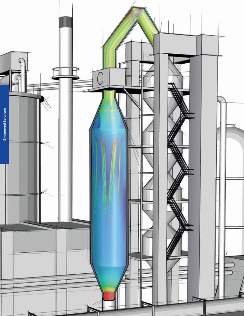
Cfd aNaLySIS
No matter what the spray application may be, the goal is always to achieve the maxi-mum effect with the minimum possible use of material, spray media and energy. It is therefore essential to have a detailed understanding of how spray mist is formed and propagated.
This is made possible by computer-assisted simulation of the flow processes of one or more media in static and dynamic environments, taking into account heat and mass transfer and almost every physical effect. These simula-tions incorporate our know-how from many decades of nozzle development.
In the past, Fluid Dynamics was only an internal tool which helped us to develop noz-zles faster and with greater precision. The completion of our high performance cluster with a computing performance of around 8.500 GFlops now allows us to offer our know-how as a service.
We can simulate nozzle applications and processes individually for your environ-ment and requirements. The aim is to make your spray processes working exactly how you want them to.
fluid dynamics simulation as a process optimization tool
Our services: � Simple flow field and pressure loss simulations with one or more gas/liquid in containers, pipes and fittings
� Full spray propagation in almost every environment including heat and mass transfer with the surrounding gases
� Calculation of the internal flow field in nozzles and prediction of the spray pattern as well as water distribution and spray characteristic close to the nozzle
your advantages: � Maximum efficiency in- media consumption for nozzles and applications- geometric dimensions of the whole process
� through optimized- nozzle selection- nozzle operation (for efficient use of pumps,
compressors and fans)- spray distribution- droplet sizes- optimized fluid flow upstream and downstream
of the spraying process
Eng
inee
red
So
lutio
ns
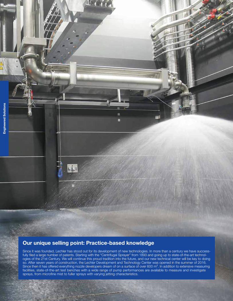
Our unique selling point: Practice-based knowledge Since it was founded, Lechler has stood out for its development of new technologies. In more than a century we have success-fully filed a large number of patents. Starting with the “Centrifugal Sprayer” from 1893 and going up to state-of-the-art technol-ogies of the 21st Century. We will continue this proud tradition into the future, and our new technical center will be key to doing so. After seven years of construction, the Lechler Development and Technology Center was opened in the summer of 2016. Since then it has offered everything nozzle developers dream of on a surface of over 600 m². In addition to extensive measuring facilities, state-of-the-art test benches with a wide range of pump performances are available to measure and investigate sprays, from microfine mist to fuller sprays with varying jetting characteristics.
37
Eng
inee
red
So
lutio
ns
mEaSUrINg TEChNOLOgyhOw OUr rESOUrCES hELP US aChIEvE PrECISION
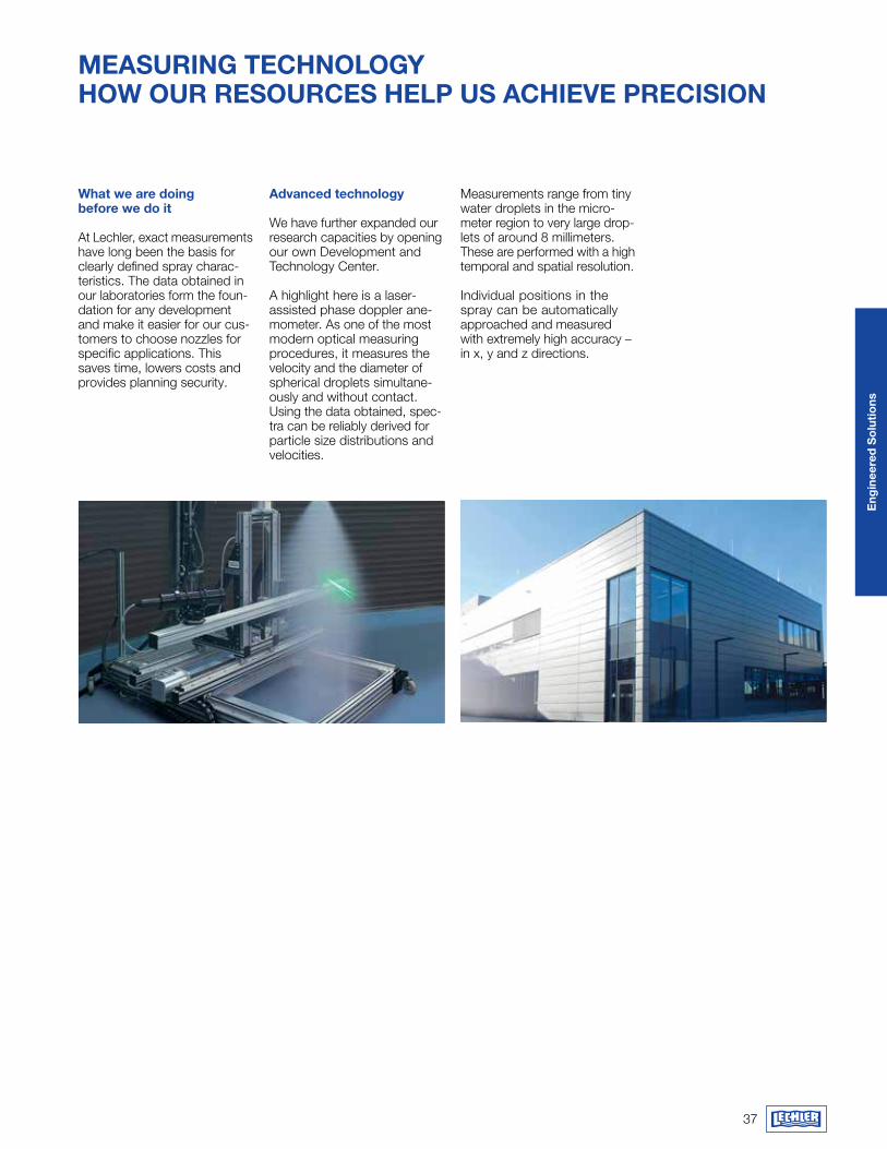
what we are doing before we do it
At Lechler, exact measurements have long been the basis for clearly defined spray charac-teristics. The data obtained in our laboratories form the foun-dation for any development and make it easier for our cus-tomers to choose nozzles for specific applications. This saves time, lowers costs and provides planning security.
advanced technology
We have further expanded our research capacities by opening our own Development and Technology Center. A highlight here is a laser- assisted phase doppler ane-mometer. As one of the most modern optical measuring procedures, it measures the velocity and the diameter of spherical droplets simultane-ously and without contact. Using the data obtained, spec-tra can be reliably derived for particle size distributions and velo cities.
Measurements range from tiny water droplets in the micro-meter region to very large drop-lets of around 8 millimeters. These are performed with a high temporal and spatial resolution.
Individual positions in the spray can be automati cally approached and measured with extremely high accuracy – in x, y and z directions.
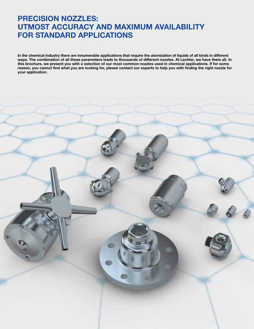
PrECISION NOzzLES:UTmOST aCCUraCy aNd maxImUm avaILaBILITy fOr STaNdard aPPLICaTIONS
In the chemical industry there are innumerable applications that require the atomization of liquids of all kinds in different ways. The combination of all these parameters leads to thousands of different nozzles. at Lechler, we have them all. In this brochure, we present you with a selection of our most common nozzles used in chemical applications. If for some reason, you cannot find what you are looking for, please contact our experts to help you with finding the right nozzle for your application.

39
Pre
cisi
on
Sp
ray
Noz
zles
Spray pattern of a single spillback nozzle
Spray pattern of a cluster spillback nozzle lance
Use: � Gas cooling in medium- sized and large gas cooling towers
Spillback nozzlesAtomization without compressed air
Lechler spillback nozzles atomize liquids as a fine hollow cone.
This single-fluid nozzle works according to the pressure atomization principle. The water is sent to the nozzle with an almost constant feed pressure, irrespectively of the atomized flow rate.
The amount of liquid injected is adjusted via a control valve in the spillback line, whereby part of the flow is taken from the inlet flow rate and carried back to the tank. The maxi mum atomized flow rate is achieved with the control valve closed.
Uniform and fine liquid atomi-zation is achieved across the entire control range.
If the volume to be atomized is distributed over cluster heads with up to six small spillback nozzles, this leads to an improvement in the droplet quality compared to a single nozzle.
Thanks to the cluster heads’ total spray angle of about 120°, the distribution of the water volume over the entire channel cross-section improves. The number of lances can be reduced in this way. We also recommend this option when upgrading existing gas cooling towers in particular.
Supply with constant feed pressure
Spillback line
hollow cone
Scheme of the spillback nozzle
Spray angle of the individual nozzles 90° or 60° as hollow cone
high turn-down ratio of up to 12:1
Properties
Low operating costs as no atomizing air required
Even and fine liquid atomization over the entire control range
Execution as single or cluster nozzle lances possible
Typical pressure range of 508 psi, g in the supply line at the nozzle
V1
V2 psi
40
Pre
cisi
on
Sp
ray
Noz
zles
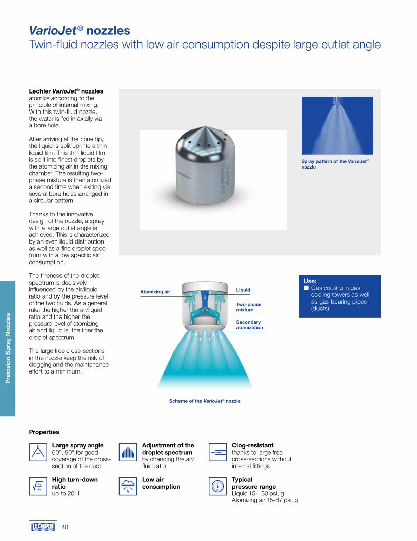
Use: � Gas cooling in gas cooling towers as well as gas-bearing pipes (ducts)
atomizing air Liquid
Two-phase mixture
Secondary atomization
VarioJet® nozzlesTwin-fluid nozzles with low air consumption despite large outlet angle
Lechler VarioJet® nozzles atomize according to the principle of internal mixing. With this twin-fluid nozzle, the water is fed in axially via a bore hole.
After arriving at the cone tip, the liquid is split up into a thin liquid film. This thin liquid film is split into finest droplets by the atomizing air in the mixing chamber. The resulting two-phase mixture is then atomized a second time when exiting via several bore holes arranged in a circular pattern.
Thanks to the innovative design of the nozzle, a spray with a large outlet angle is achieved. This is characte rized by an even liquid distribution as well as a fine droplet spec-trum with a low specific air consumption.
The fineness of the droplet spectrum is decisively influenced by the air/liquid ratio and by the pressure level of the two fluids. As a general rule: the higher the air/liquid ratio and the higher the pressure level of atomizing air and liquid is, the finer the droplet spectrum.
The large free cross-sections in the nozzle keep the risk of clogging and the maintenance effort to a minimum.
Scheme of the VarioJet® nozzle
Large spray angle 60°, 90° for good coverage of the cross- section of the duct
high turn-down ratio up to 20 :1
Properties
adjustment of the droplet spectrum by changing the air/fluid ratio
Low air consumption
Clog-resistant thanks to large free cross-sections without internal fittings
Typical pressure range Liquid 15-130 psi, g Atomizing air 15-87 psi, g
V1
V2 psi
Spray pattern of the VarioJet® nozzle
41
Pre
cisi
on
Sp
ray
Noz
zles
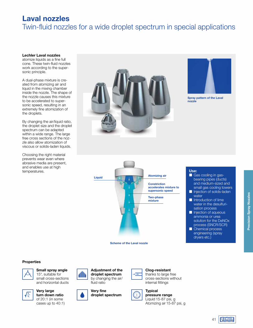
Use: � Gas cooling in gas- bearing pipes (ducts) and medium-sized and small gas cooling towers
� Injection of solids-laden water
� Introduction of lime water in the desulfuri-sation process
� Injection of aqueous ammonia or urea solution for the DeNOx process (SNCR/SCR)
� Chemical process engineering (spray dryers etc.)
Liquidatomizing air
Two-phase mixture
Constriction accelerates mixture to supersonic speed
Laval nozzlesTwin-fluid nozzles for a wide droplet spectrum in special applications
Lechler Laval nozzles atomize liquids as a fine full cone. These twin-fluid nozzles work according to the super-sonic principle.
A dual-phase mixture is cre-ated from atomizing air and liquid in the mixing chamber inside the nozzle. The shape of the nozzle causes this mixture to be accelerated to super-sonic speed, resulting in an extremely fine atomization of the droplets.
By changing the air/liquid ratio, the droplet size and the droplet spectrum can be adapted within a wide range. The large free cross sections of the noz-zle also allow atomization of viscous or solids-laden liquids.
Choosing the right material prevents wear even where abrasive media are present, and enables use at high temperatures.
Small spray angle 15°, suitable for small cross-sections and horizontal ducts
very large turn down ratio of 20:1 ( in some cases up to 40:1)
Properties
adjustment of the droplet spectrum by changing the air/ fluid ratio
Very fine droplet spectrum
Clog-resistant thanks to large free cross-sections without internal fittings
Typical pressure range Liquid 15-87 psi, g Atomizing air 15-87 psi, g
psi
Scheme of the Laval nozzle
Spray pattern of the Laval nozzle
V1
V2
42
Pre
cisi
on
Sp
ray
Noz
zles
H
H1
Water MaterialCu-ISOPLAN 750
1Hex
Air
2Hex
L Li
quid
L Gas
G G
as
Ø D
G Liquid
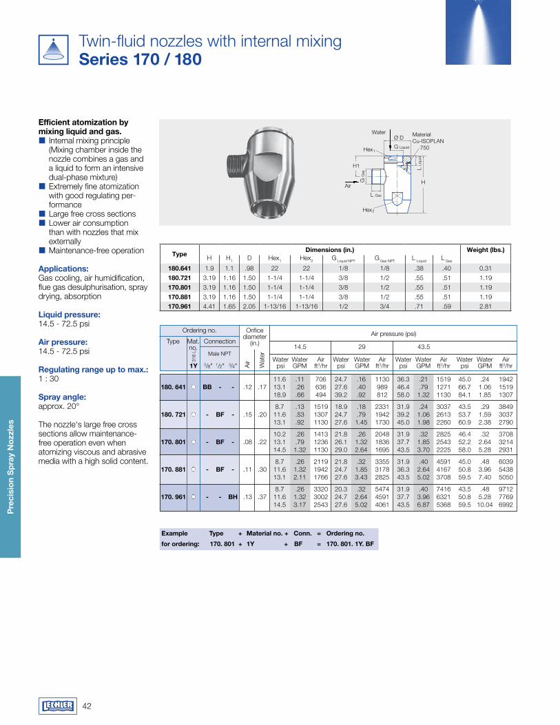
Twin-fluid nozzles with internal mixingSeries 170 / 180
Efficient atomization by mixing liquid and gas.�� Internal mixing principle (Mixing chamber inside the nozzle combines a gas and a liquid to form an intensive dual-phase mixture)�� Extremely fine atomization with good regulating per-formance�� Large free cross sections�� Lower air consumption than with nozzles that mix externally�� Maintenance-free operation
applications:Gas cooling, air humidification, flue gas desulphurisation, spray drying, absorption Liquid pressure:14.5 - 72.5 psi
air pressure: 14.5 - 72.5 psi
regulating range up to max.:1 : 30
Spray angle: approx. 20°
The nozzle‘s large free cross sections allow maintenance- free operation even when atomizing viscous and abrasive media with a high solid content.
Typedimensions (in.) weight (lbs.)
H H1 D Hex1 Hex2 G Liquid NPT G Gas NPT L Liquid L Gas
180.641 1.9 1.1 .98 22 22 1/8 1/8 .38 .40 0.31180.721 3.19 1.16 1.50 1-1/4 1-1/4 3/8 1/2 .55 .51 1.19170.801 3.19 1.16 1.50 1-1/4 1-1/4 3/8 1/2 .55 .51 1.19170.881 3.19 1.16 1.50 1-1/4 1-1/4 3/8 1/2 .55 .51 1.19170.961 4.41 1.65 2.05 1-13/16 1-13/16 1/2 3/4 .71 .59 2.81
Air pressure (psi)
316
L
Air
Ordering no.
Male NPT Water Water Air Water Water Air Water Water Air Water Water Air 1y 3/8" 1/2" 3/4" psi GPM ft3/hr psi GPM ft3/hr psi GPM ft3/hr psi GPM ft3/hr
Type Mat. no.
Connection
Orifice diameter
(in.)
Wat
er
14.5 29 43.5
for ordering: 170. 801 + 1y + Bf = 170. 801. 1y. Bf
Example Type + material no. + Conn. = Ordering no.
11.6 .11 706 24.7 .16 1130 36.3 .21 1519 45.0 .24 1942 180. 641 BB - - .12 .17 13.1 .26 636 27.6 .40 989 46.4 .79 1271 66.7 1.06 1519 18.9 .66 494 39.2 .92 812 58.0 1.32 1130 84.1 1.85 1307
8.7 .13 1519 18.9 .18 2331 31.9 .24 3037 43.5 .29 3849 180. 721 - Bf - .15 .20 11.6 .53 1307 24.7 .79 1942 39.2 1.06 2613 53.7 1.59 3037 13.1 .92 1130 27.6 1.45 1730 45.0 1.98 2260 60.9 2.38 2790
10.2 .26 1413 21.8 .26 2048 31.9 .32 2825 46.4 .32 3708 170. 801 - Bf - .08 .22 13.1 .79 1236 26.1 1.32 1836 37.7 1.85 2543 52.2 2.64 3214 14.5 1.32 1130 29.0 2.64 1695 43.5 3.70 2225 58.0 5.28 2931
8.7 .26 2119 21.8 .32 3355 31.9 .40 4591 45.0 .48 6039 170. 881 - Bf - .11 .30 11.6 1.32 1942 24.7 1.85 3178 36.3 2.64 4167 50.8 3.96 5438 13.1 2.11 1766 27.6 3.43 2825 43.5 5.02 3708 59.5 7.40 5050
8.7 .26 3320 20.3 .32 5474 31.9 .40 7416 43.5 .48 9712 170. 961 - - Bh .13 .37 11.6 1.32 3002 24.7 2.64 4591 37.7 3.96 6321 50.8 5.28 7769 14.5 3.17 2543 27.6 5.02 4061 43.5 6.87 5368 59.5 10.04 6992
43
Pre
cisi
on
Sp
ray
Noz
zles
H
D
GW
L1
L
GL
Hex1
Ø BHex
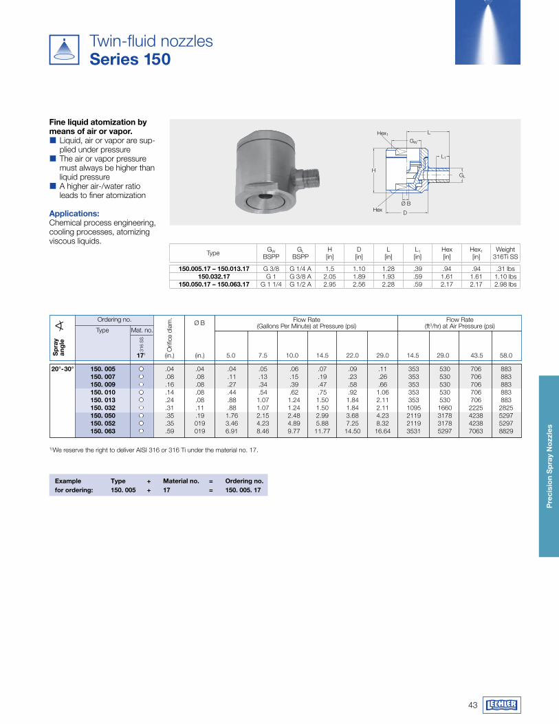
Twin-fluid nozzlesSeries 150
fine liquid atomization by means of air or vapor.�� Liquid, air or vapor are sup-plied under pressure�� The air or vapor pressure must always be higher than liquid pressure�� A higher air-/water ratio leads to finer atomization
applications:Chemical process engineering, cooling processes, atomizing viscous liquids.
Type GW
BSPPGL
BSPPH[in]
D[in]
L[in]
L1
[in]Hex[in]
Hex1
[in]Weight
316Ti SS
150.005.17 – 150.013.17 G 3/8 G 1/4 A 1.5 1.10 1.28 .39 .94 .94 .31 lbs 150.032.17 G 1 G 3/8 A 2.05 1.89 1.93 .59 1.61 1.61 1.10 lbs
150.050.17 – 150.063.17 G 1 1/4 G 1/2 A 2.95 2.56 2.28 .59 2.17 2.17 2.98 lbs
Example Type + material no. = Ordering no.for ordering: 150. 005 + 17 = 150. 005. 17
1) We reserve the right to deliver AISI 316 or 316 Ti under the material no. 17.
Flow Rate(Gallons Per Minute) at Pressure (psi)
Orif
ice
diam
.Ordering no.
Type Mat. no.
171 (in.) (in.) 5.0 7.5 10.0 14.5 22.0 29.0 14.5 29.0 43.5 58.0
316
SS
Sp
ray
ang
le
Ø B Flow Rate(ft3/hr) at Air Pressure (psi)
20°-30° 150. 005 .04 .04 .04 .05 .06 .07 .09 .11 353 530 706 883 150. 007 .08 .08 .11 .13 .15 .19 .23 .26 353 530 706 883 150. 009 .16 .08 .27 .34 .39 .47 .58 .66 353 530 706 883 150. 010 .14 .08 .44 .54 .62 .75 .92 1.06 353 530 706 883 150. 013 .24 .08 .88 1.07 1.24 1.50 1.84 2.11 353 530 706 883 150. 032 .31 .11 .88 1.07 1.24 1.50 1.84 2.11 1095 1660 2225 2825 150. 050 .35 .19 1.76 2.15 2.48 2.99 3.68 4.23 2119 3178 4238 5297 150. 052 .35 019 3.46 4.23 4.89 5.88 7.25 8.32 2119 3178 4238 5297 150. 063 .59 019 6.91 8.46 9.77 11.77 14.50 16.64 3531 5297 7063 8829
44
Pre
cisi
on
Sp
ray
Noz
zles
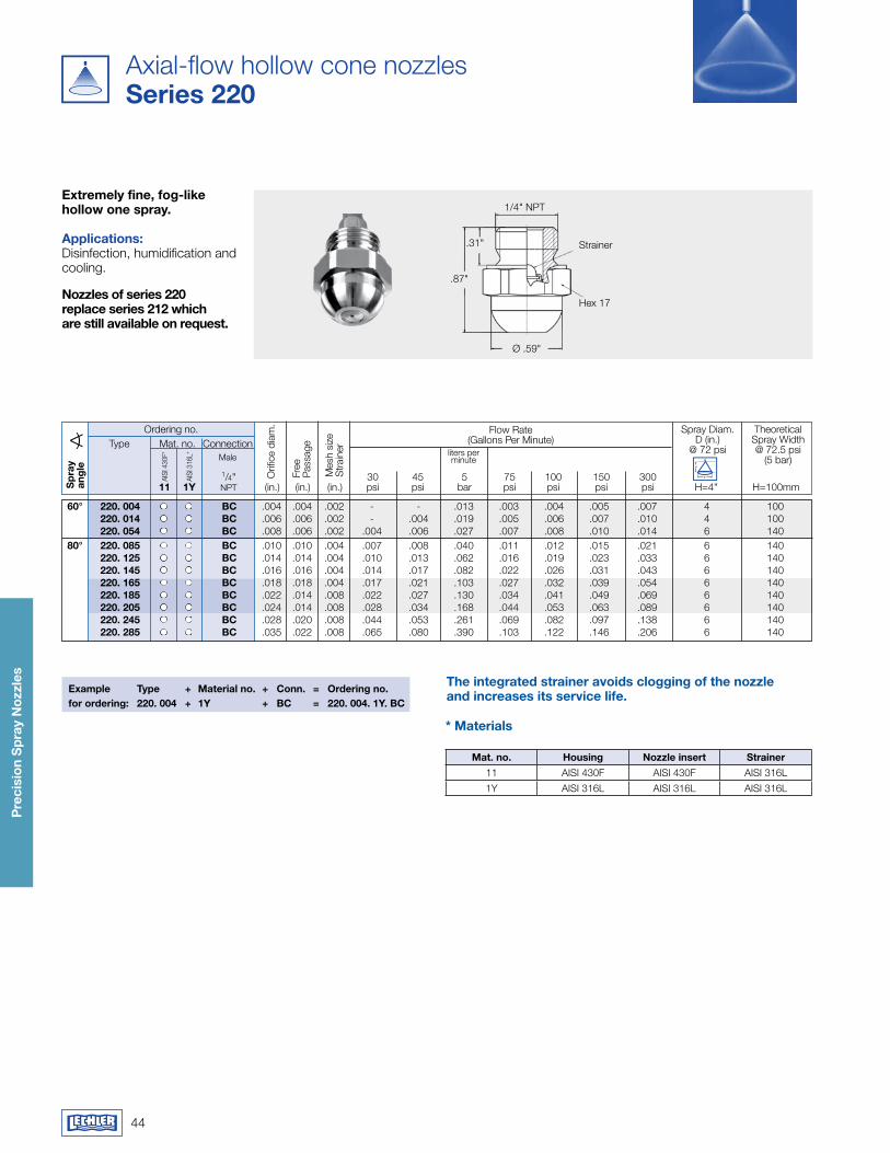
Axial-flow hollow cone nozzlesSeries 220
Extremely fine, fog-like hollow one spray.
applications:Disinfection, humidification and cooling.
1/4" NPT
Strainer
Hex 17
Ø .59"
.87"
.31"
Nozzles of series 220 replace series 212 which are still available on request.
Example Type + material no. + Conn. = Ordering no.for ordering: 220. 004 + 1y + BC = 220. 004. 1y. BC
The integrated strainer avoids clogging of the nozzle and increases its service life.
mat. no. housing Nozzle insert Strainer11 AISI 430F AISI 430F AISI 316L
1Y AISI 316L AISI 316L AISI 316L
* materials
Ordering no. Flow Rate(Gallons Per Minute)
Theoretical Spray Width @ 72.5 psi
(5 bar)
Mat. no.
AISI
316
L* liters per minute
ConnectionMale
Orif
ice
diam
.
Free
Pa
ssag
eType
1/4" 30 45 5 75 100 150 300 11 1y NPT (in.) (in.) (in.) psi psi bar psi psi psi psi H=4" H=100mmS
pra
y an
gle
Spray Diam.D (in.)
@ 72 psi
AISI
430
F*
Mes
h si
zeS
train
er
60° 220. 004 BC .004 .004 .002 - - .013 .003 .004 .005 .007 4 100 220. 014 BC .006 .006 .002 - .004 .019 .005 .006 .007 .010 4 100 220. 054 BC .008 .006 .002 .004 .006 .027 .007 .008 .010 .014 6 140 80° 220. 085 BC .010 .010 .004 .007 .008 .040 .011 .012 .015 .021 6 140 220. 125 BC .014 .014 .004 .010 .013 .062 .016 .019 .023 .033 6 140 220. 145 BC .016 .016 .004 .014 .017 .082 .022 .026 .031 .043 6 140 220. 165 BC .018 .018 .004 .017 .021 .103 .027 .032 .039 .054 6 140 220. 185 BC .022 .014 .008 .022 .027 .130 .034 .041 .049 .069 6 140 220. 205 BC .024 .014 .008 .028 .034 .168 .044 .053 .063 .089 6 140 220. 245 BC .028 .020 .008 .044 .053 .261 .069 .082 .097 .138 6 140 220. 285 BC .035 .022 .008 .065 .080 .390 .103 .122 .146 .206 6 140
H
D
45
Pre
cisi
on
Sp
ray
Noz
zles
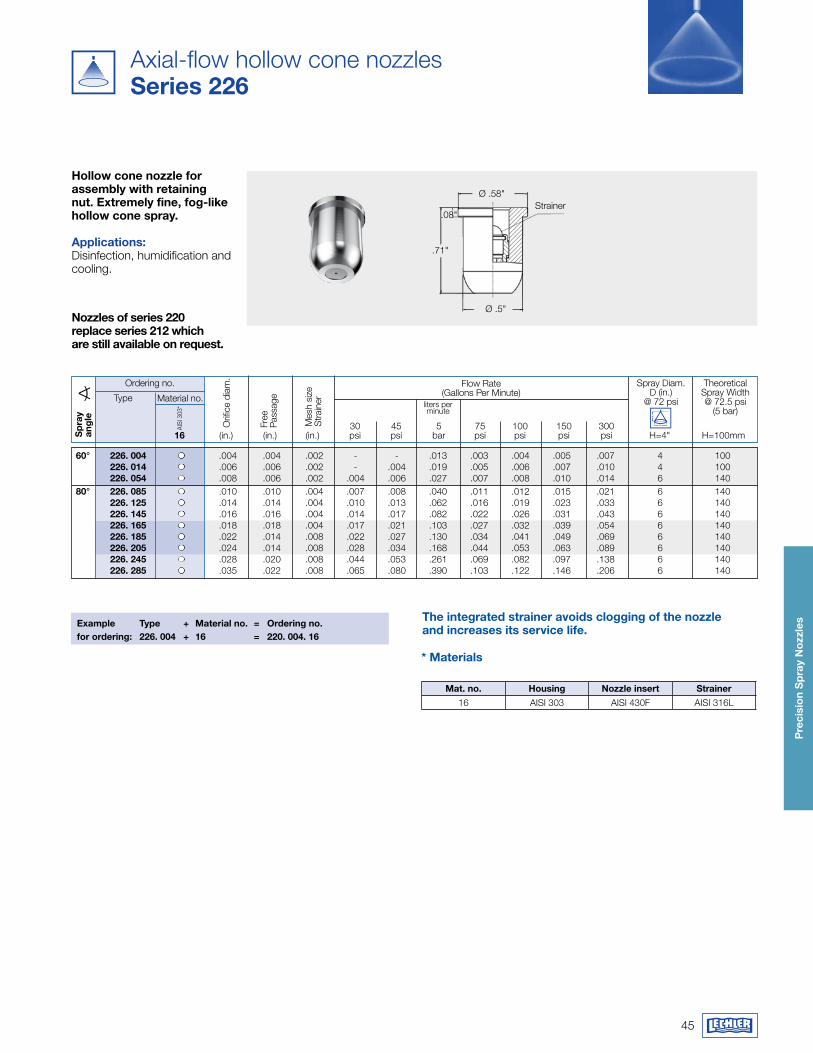
Axial-flow hollow cone nozzlesSeries 226
hollow cone nozzle for assembly with retaining nut. Extremely fine, fog-like hollow cone spray.
applications:Disinfection, humidification and cooling.
Ø .58"Strainer
Ø .5"
.71"
.08"
Nozzles of series 220 replace series 212 which are still available on request.
Example Type + material no. = Ordering no.for ordering: 226. 004 + 16 = 220. 004. 16
The integrated strainer avoids clogging of the nozzle and increases its service life.
mat. no. housing Nozzle insert Strainer16 AISI 303 AISI 430F AISI 316L
* materials
Ordering no. Flow Rate(Gallons Per Minute)
Theoretical Spray Width @ 72.5 psi
(5 bar)Material no.
liters per minute
Orif
ice
diam
.
Free
Pa
ssag
eType
30 45 5 75 100 150 300 16 (in.) (in.) (in.) psi psi bar psi psi psi psi H=4" H=100mmS
pra
y an
gle
Spray Diam.D (in.)
@ 72 psi
AISI
303
*
Mes
h si
zeS
train
er
60° 226. 004 .004 .004 .002 - - .013 .003 .004 .005 .007 4 100 226. 014 .006 .006 .002 - .004 .019 .005 .006 .007 .010 4 100 226. 054 .008 .006 .002 .004 .006 .027 .007 .008 .010 .014 6 140 80° 226. 085 .010 .010 .004 .007 .008 .040 .011 .012 .015 .021 6 140 226. 125 .014 .014 .004 .010 .013 .062 .016 .019 .023 .033 6 140 226. 145 .016 .016 .004 .014 .017 .082 .022 .026 .031 .043 6 140 226. 165 .018 .018 .004 .017 .021 .103 .027 .032 .039 .054 6 140 226. 185 .022 .014 .008 .022 .027 .130 .034 .041 .049 .069 6 140 226. 205 .024 .014 .008 .028 .034 .168 .044 .053 .063 .089 6 140 226. 245 .028 .020 .008 .044 .053 .261 .069 .082 .097 .138 6 140 226. 285 .035 .022 .008 .065 .080 .390 .103 .122 .146 .206 6 140
H
D
46
Pre
cisi
on
Sp
ray
Noz
zles
Conversion formula for the above series: v.
2 = v.
1 *p2 p1
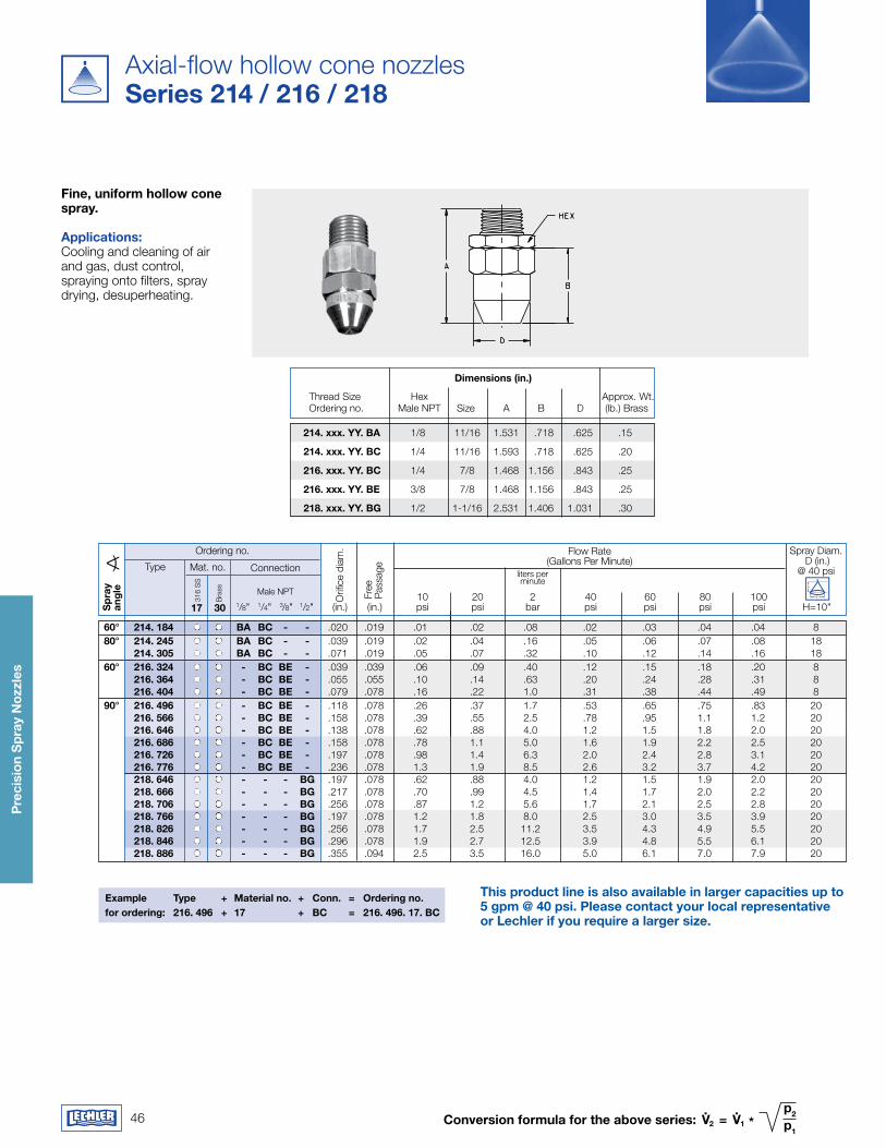
Axial-flow hollow cone nozzlesSeries 214 / 216 / 218
fine, uniform hollow cone spray.
applications:Cooling and cleaning of air and gas, dust control, spraying onto filters, spray drying, desuperheating.
Example Type + material no. + Conn. = Ordering no.for ordering: 216. 496 + 17 + BC = 216. 496. 17. BC
Ordering no. Flow Rate(Gallons Per Minute)
Spray Diam. D (in.)
@ 40 psiMat. no.
316
SS
Bra
ss
17 30
liters per minute
Connection
Male NPT
Orif
ice
diam
.
Thread Size Hex Approx. Wt. Ordering no. Male NPT Size A B D (lb.) Brass
This product line is also available in larger capacities up to 5 gpm @ 40 psi. Please contact your local representative or Lechler if you require a larger size.
Free
Pa
ssag
eType
10 20 2 40 60 80 100 1/8" 1/4" 3/8" 1/2" (in.) (in.) psi psi bar psi psi psi psi H=10"S
pra
y an
gle
214. xxx. yy. Ba 1/8 11/16 1.531 .718 .625 .15
214. xxx. yy. BC 1/4 11/16 1.593 .718 .625 .20
216. xxx. yy. BC 1/4 7/8 1.468 1.156 .843 .25
216. xxx. yy. BE 3/8 7/8 1.468 1.156 .843 .25
218. xxx. yy. Bg 1/2 1-1/16 2.531 1.406 1.031 .30
60° 214. 184 Ba BC - - .020 .019 .01 .02 .08 .02 .03 .04 .04 8 80° 214. 245 Ba BC - - .039 .019 .02 .04 .16 .05 .06 .07 .08 18 214. 305 Ba BC - - .071 .019 .05 .07 .32 .10 .12 .14 .16 18 60° 216. 324 - BC BE - .039 .039 .06 .09 .40 .12 .15 .18 .20 8 216. 364 - BC BE - .055 .055 .10 .14 .63 .20 .24 .28 .31 8 216. 404 - BC BE - .079 .078 .16 .22 1.0 .31 .38 .44 .49 8 90° 216. 496 - BC BE - .118 .078 .26 .37 1.7 .53 .65 .75 .83 20 216. 566 - BC BE - .158 .078 .39 .55 2.5 .78 .95 1.1 1.2 20 216. 646 - BC BE - .138 .078 .62 .88 4.0 1.2 1.5 1.8 2.0 20 216. 686 - BC BE - .158 .078 .78 1.1 5.0 1.6 1.9 2.2 2.5 20 216. 726 - BC BE - .197 .078 .98 1.4 6.3 2.0 2.4 2.8 3.1 20 216. 776 - BC BE - .236 .078 1.3 1.9 8.5 2.6 3.2 3.7 4.2 20 218. 646 - - - Bg .197 .078 .62 .88 4.0 1.2 1.5 1.9 2.0 20 218. 666 - - - Bg .217 .078 .70 .99 4.5 1.4 1.7 2.0 2.2 20 218. 706 - - - Bg .256 .078 .87 1.2 5.6 1.7 2.1 2.5 2.8 20 218. 766 - - - Bg .197 .078 1.2 1.8 8.0 2.5 3.0 3.5 3.9 20 218. 826 - - - Bg .256 .078 1.7 2.5 11.2 3.5 4.3 4.9 5.5 20 218. 846 - - - Bg .296 .078 1.9 2.7 12.5 3.9 4.8 5.5 6.1 20 218. 886 - - - Bg .355 .094 2.5 3.5 16.0 5.0 6.1 7.0 7.9 20
dimensions (in.)
H
D
47
Pre
cisi
on
Sp
ray
Noz
zles
Flow Rate(Gallons Per Minute)
Spray Anglein degrees at
316
SS
Orif
ice
diam
.Ordering no.
Female NPT 3 5 7 10 15 20 2 40 60 3 7 15 17 3" 4" (in.) psi psi psi psi psi psi bar psi psi psi psi psi
Type Mat. no. Connectionliters per minute
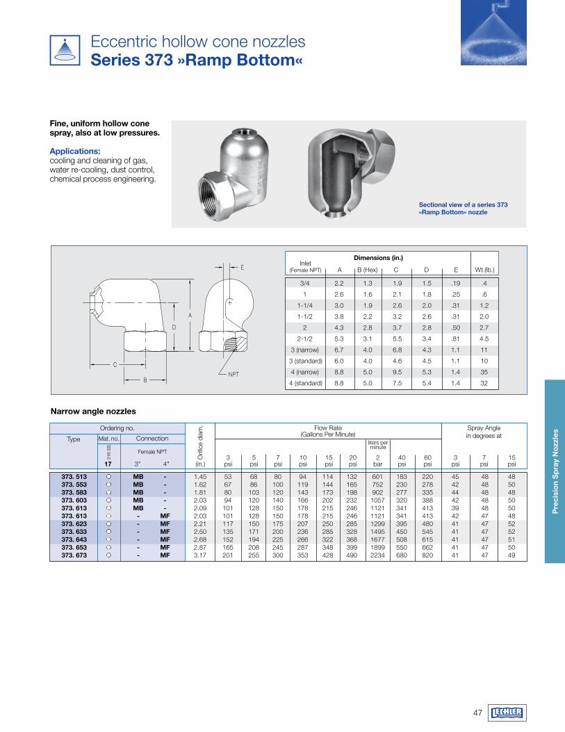
373. 513 mB - 1.45 53 68 80 94 114 132 601 183 220 45 48 48373. 553 mB - 1.62 67 86 100 119 144 165 752 230 278 42 48 50373. 583 mB - 1.81 80 103 120 143 173 198 902 277 335 44 48 48373. 603 mB - 2.03 94 120 140 166 202 232 1057 320 388 42 48 50373. 613 mB - 2.09 101 128 150 178 215 246 1121 341 413 39 48 50373. 613 - mf 2.03 101 128 150 178 215 246 1121 341 413 42 47 48373. 623 - mf 2.21 117 150 175 207 250 285 1299 395 480 41 47 52373. 633 - mf 2.50 135 171 200 236 285 328 1495 450 545 41 47 52373. 643 - mf 2.68 152 194 225 266 322 368 1677 508 615 41 47 51373. 653 - mf 2.87 165 208 245 287 348 399 1899 550 662 41 47 50373. 673 - mf 3.17 201 255 300 353 428 490 2234 680 820 41 47 49
Inlet (Female NPT) A B (Hex) C D E Wt.(lb.)
dimensions (in.)
3/4 2.2 1.3 1.9 1.5 .19 .4
1 2.6 1.6 2.1 1.8 .25 .6
1-1/4 3.0 1.9 2.6 2.0 .31 1.2
1-1/2 3.8 2.2 3.2 2.6 .31 2.0
2 4.3 2.8 3.7 2.8 .50 2.7
2-1/2 5.3 3.1 5.5 3.4 .81 4.5
3 (narrow) 6.7 4.0 6.8 4.3 1.1 11
3 (standard) 6.0 4.0 4.6 4.5 1.1 10
4 (narrow) 8.8 5.0 9.5 5.3 1.4 35
4 (standard) 8.8 5.0 7.5 5.4 1.4 32
Narrow angle nozzles
Sectional view of a series 373 »ramp Bottom« nozzle
This product line is also available in larger capacities up to 5 gpm @ 40 psi. Please contact your local representative or Lechler if you require a larger size.
Eccentric hollow cone nozzlesSeries 373 »ramp Bottom«
fine, uniform hollow cone spray, also at low pressures.
applications: cooling and cleaning of gas, water re-cooling, dust control, chemical process engineering.
48
Pre
cisi
on
Sp
ray
Noz
zles
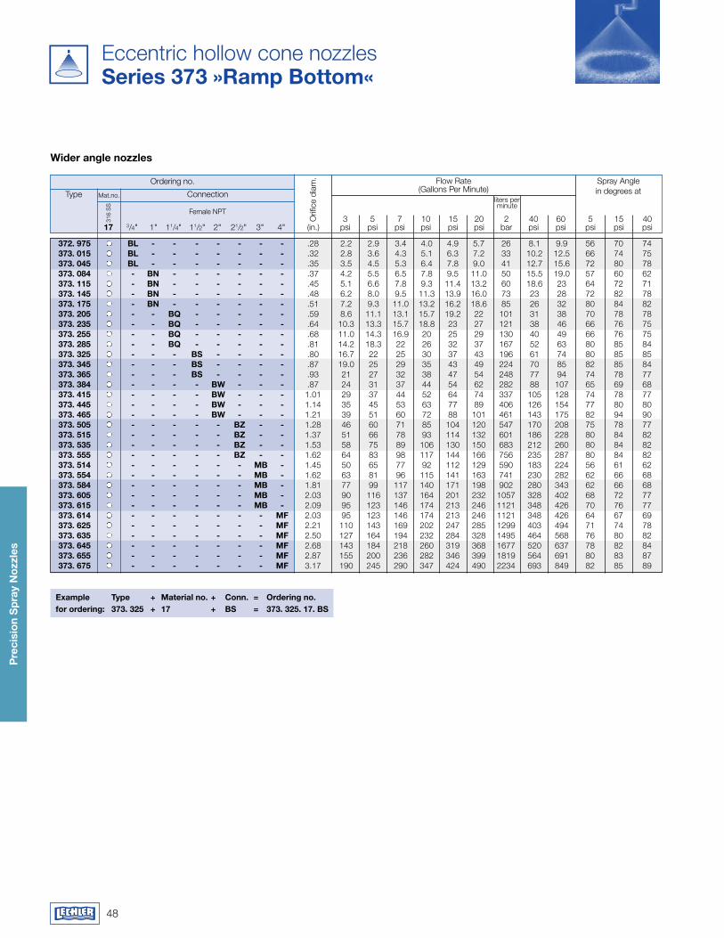
Eccentric hollow cone nozzlesSeries 373 »ramp Bottom«
Flow Rate(Gallons Per Minute)
Spray Anglein degrees at
316
SS
Orif
ice
diam
.Ordering no.
Female NPT 3 5 7 10 15 20 2 40 60 5 15 40 17 3/4" 1" 11/4" 11/2" 2" 21/2" 3" 4" (in.) psi psi psi psi psi psi bar psi psi psi psi psi
Type Mat.no. Connectionliters per minute
Example Type + material no. + Conn. = Ordering no.for ordering: 373. 325 + 17 + BS = 373. 325. 17. BS
wider angle nozzles
372. 975 BL - - - - - - - .28 2.2 2.9 3.4 4.0 4.9 5.7 26 8.1 9.9 56 70 74373. 015 BL - - - - - - - .32 2.8 3.6 4.3 5.1 6.3 7.2 33 10.2 12.5 66 74 75373. 045 BL - - - - - - - .35 3.5 4.5 5.3 6.4 7.8 9.0 41 12.7 15.6 72 80 78373. 084 - BN - - - - - - .37 4.2 5.5 6.5 7.8 9.5 11.0 50 15.5 19.0 57 60 62373. 115 - BN - - - - - - .45 5.1 6.6 7.8 9.3 11.4 13.2 60 18.6 23 64 72 71373. 145 - BN - - - - - - .48 6.2 8.0 9.5 11.3 13.9 16.0 73 23 28 72 82 78373. 175 - BN - - - - - - .51 7.2 9.3 11.0 13.2 16.2 18.6 85 26 32 80 84 82373. 205 - - BQ - - - - - .59 8.6 11.1 13.1 15.7 19.2 22 101 31 38 70 78 78373. 235 - - BQ - - - - - .64 10.3 13.3 15.7 18.8 23 27 121 38 46 66 76 75373. 255 - - BQ - - - - - .68 11.0 14.3 16.9 20 25 29 130 40 49 66 76 75373. 285 - - BQ - - - - - .81 14.2 18.3 22 26 32 37 167 52 63 80 85 84373. 325 - - - BS - - - - .80 16.7 22 25 30 37 43 196 61 74 80 85 85373. 345 - - - BS - - - - .87 19.0 25 29 35 43 49 224 70 85 82 85 84373. 365 - - - BS - - - - .93 21 27 32 38 47 54 248 77 94 74 78 77373. 384 - - - - Bw - - - .87 24 31 37 44 54 62 282 88 107 65 69 68373. 415 - - - - Bw - - - 1.01 29 37 44 52 64 74 337 105 128 74 78 77373. 445 - - - - Bw - - - 1.14 35 45 53 63 77 89 406 126 154 77 80 80373. 465 - - - - Bw - - - 1.21 39 51 60 72 88 101 461 143 175 82 94 90373. 505 - - - - - Bz - - 1.28 46 60 71 85 104 120 547 170 208 75 78 77373. 515 - - - - - Bz - - 1.37 51 66 78 93 114 132 601 186 228 80 84 82373. 535 - - - - - Bz - - 1.53 58 75 89 106 130 150 683 212 260 80 84 82373. 555 - - - - - Bz - - 1.62 64 83 98 117 144 166 756 235 287 80 84 82373. 514 - - - - - - mB - 1.45 50 65 77 92 112 129 590 183 224 56 61 62373. 554 - - - - - - mB - 1.62 63 81 96 115 141 163 741 230 282 62 66 68373. 584 - - - - - - mB - 1.81 77 99 117 140 171 198 902 280 343 62 66 68373. 605 - - - - - - mB - 2.03 90 116 137 164 201 232 1057 328 402 68 72 77373. 615 - - - - - - mB - 2.09 95 123 146 174 213 246 1121 348 426 70 76 77373. 614 - - - - - - - mf 2.03 95 123 146 174 213 246 1121 348 426 64 67 69373. 625 - - - - - - - mf 2.21 110 143 169 202 247 285 1299 403 494 71 74 78373. 635 - - - - - - - mf 2.50 127 164 194 232 284 328 1495 464 568 76 80 82373. 645 - - - - - - - mf 2.68 143 184 218 260 319 368 1677 520 637 78 82 84373. 655 - - - - - - - mf 2.87 155 200 236 282 346 399 1819 564 691 80 83 87373. 675 - - - - - - - mf 3.17 190 245 290 347 424 490 2234 693 849 82 85 89
49
Pre
cisi
on
Sp
ray
Noz
zles
Conversion formula for the above series: v.
2 = v.
1 *p2 p1
( )0.4
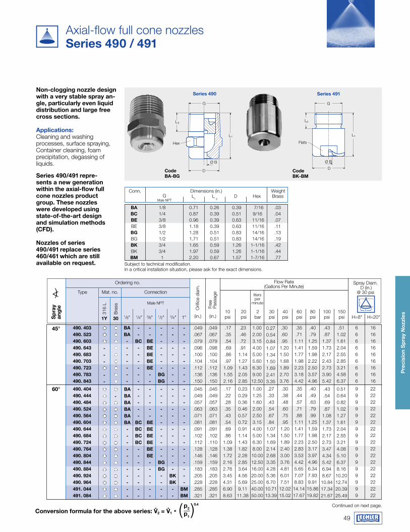
Series 490 Series 491
D
G
L1
L2
Hex
Ø B
G
D
Ø B
Flats
L1
L2
Code Ba-Bg
Code Bk-BmSeries 490/491 repre-
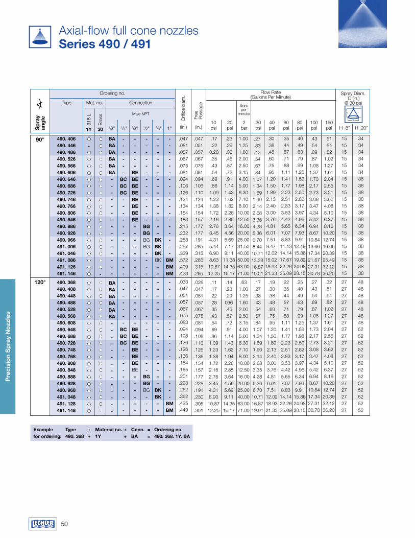
sents a new generation within the axial-flow full cone nozzles product group. These nozzles were developed using state-of-the-art design and simulation methods (Cfd).
Nozzles of series 490/491 replace series 460/461 which are still available on request.
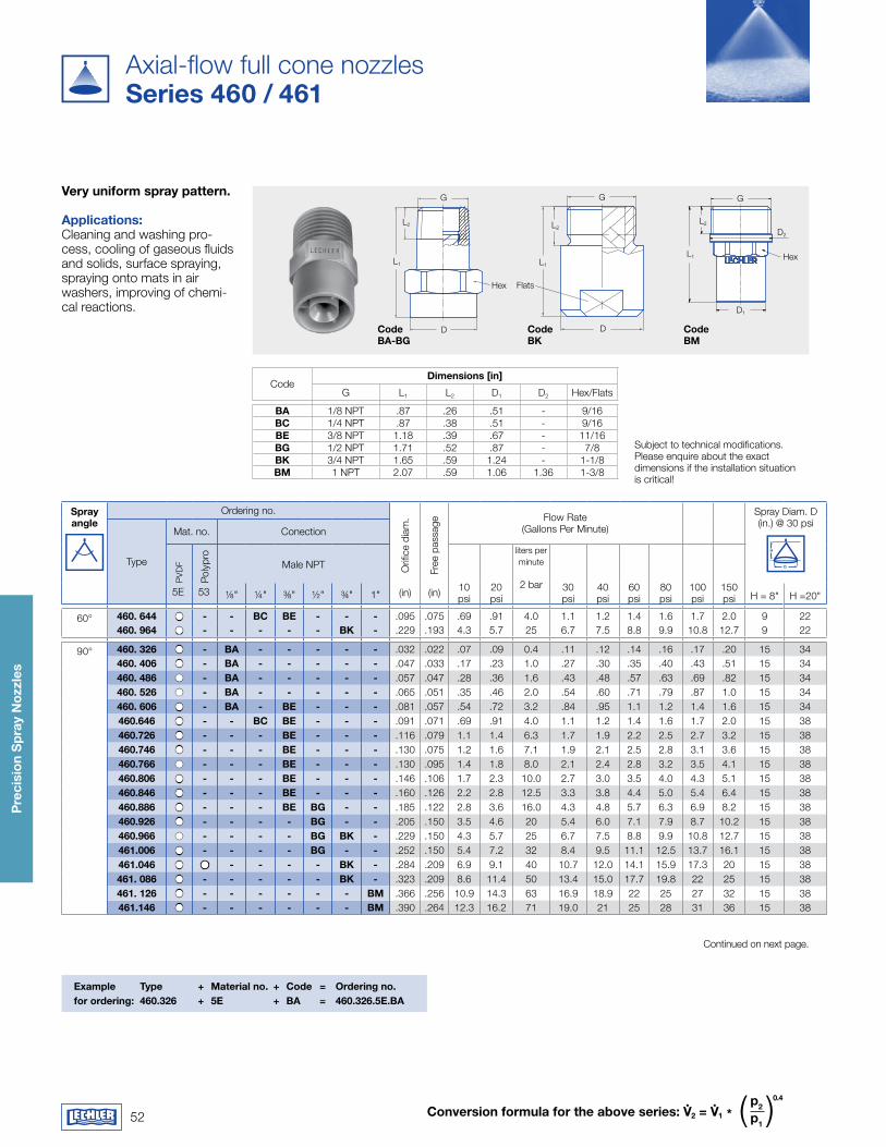
Axial-flow full cone nozzlesSeries 490 / 491
Non-clogging nozzle design with a very stable spray an-gle, particularly even liquid distribution and large free cross sections. applications:Cleaning and washing processes, surface spraying, Container cleaning, foam precipitation, degassing of liquids.
Continued on next page.
Spray Diam. D (in.)
@ 30 psi
Sp
ray
ang
le
Ordering no.
Type Mat. no. Connection
Male NPT
316
L
(in.)301y
Bra
ss
<) 10 20 2 30 40 60 80 100 150 psi psi bar psi psi psi psi psi psi H=8" H=20"
Orif
ice
diam
.
Free
Pa
ssag
e
Flow Rate(Gallons Per Minute)
liters per
minute
1/8" 1/4" 3/8" 1/2" 3/4" 1" (in.)
45°
60°
.049
.067
.079
.096
.100
.104
.112
.136
.150
.049
.067
.079
.098
.100
.104
.112
.136
.150
.17
.35
.54
.69
.86
.971.091.552.16
.23
.46
.72
.911.141.271.432.052.85
1.002.003.154.005.005.606.309.00
12.50
0.270.540.841.071.341.501.692.413.35
.30
.60
.951.201.501.681.892.703.76
.35
.711.111.411.771.982.233.184.42
.40
.791.251.591.982.222.503.574.96
666666666
161616161616161616
.045
.049
.057
.063
.071
.081
.091
.102
.112
.128
.146
.159
.183
.205
.228
.285
.321
.045
.049
.057
.063
.071
.081
.091
.102
.110
.128
.146
.159
.183
.205
.228
.285
.321
.17
.22
.28
.35
.43
.54
.69
.861.091.381.722.162.763.454.316.908.63
0.230.290.360.460.570.720.911.141.431.822.282.853.644.565.699.11
11.38
1.001.251.602.002.503.154.005.006.308.00
10.0012.5016.0020.0025.0040.0050.00
.27
.33
.43
.54
.67
.841.071.341.692.142.683.354.285.366.70
10.7113.39
.30
.38
.48
.60
.75
.951.201.501.892.403.003.764.816.017.51
12.0215.02
.35
.44
.57
.71
.881.111.411.772.232.833.534.425.657.078.83
14.1417.67
.40
.49
.63
.79
.991.251.591.982.503.173.974.966.347.939.91
15.8619.82
99999999999999999
2222222222222222222222222222222222
-
-----
BCBCBCBC--------
-----
BEBEBEBEBEBE------
-----------
BgBg----
-------------
BkBk--
---------------
BmBm
BaBaBaBaBaBa-----------
490. 404490. 444490. 484490. 524490. 564490. 604490. 644490. 684490. 724490. 764490. 804490. 844490. 884490. 924490. 964491. 044491. 084
---
--
--
BC------
--
BEBEBEBEBE--
-------
BgBg
---------
---------
BaBa-------
490. 403490. 523490. 603490. 643490. 683490. 703490. 723490. 783490. 843
.43
.871.371.732.172.432.733.905.42
.511.021.612.042.552.853.214.586.37
.43
.54
.69
.871.081.371.732.172.733.474.345.426.948.67
10.8417.3421.67
0.510.640.821.021.271.612.042.553.214.085.106.378.16
10.2012.7420.3925.49
Subject to technical modification.In a critical installation situation, please ask for the exact dimensions.
L1 L 2 D Hex BrassG
Male NPT
Conn. Dimensions (in.) Weight
Ba 1/8 0.71 0.26 0.39 7/16 .03 BC 1/4 0.87 0.39 0.51 9/16 .04 BE 3/8 0.96 0.39 0.63 11/16 .07 BE 3/8 1.18 0.39 0.63 11/16 .11 Bg 1/2 1.28 0.51 0.83 14/16 .13 BG 1/2 1.71 0.51 0.83 14/16 .19 Bk 3/4 1.65 0.59 1.26 1-1/16 .42 BK 3/4 1.97 0.59 1.26 1-1/16 .44 Bm 1 2.20 0.67 1.57 1-7/16 .77
H
D
50
Pre
cisi
on
Sp
ray
Noz
zles
Axial-flow full cone nozzlesSeries 490 / 491
Spray Diam. D (in.)
@ 30 psi
Sp
ray
ang
le
Ordering no.
Type Mat. no. Connection
Male NPT
316
L
(in.) (in.)301y
Bra
ss<)
10 20 2 30 40 60 80 100 150 psi psi bar psi psi psi psi psi psi H=8" H=20"
Orif
ice
diam
.
Free
Pa
ssag
e
Flow Rate(Gallons Per Minute)
liters per
minute
1/8" 1/4" 3/8" 1/2" 3/4" 1"
Example Type + material no. + Conn. = Ordering no.for ordering: 490. 368 + 1y + Ba = 490. 368. 1y. Ba
90°
120°
BaBaBaBaBa Ba--------------
-------
BCBCBC----------
-------
BEBEBEBEBEBEBE------
--------------
BgBgBG---
----------------
BkBk--
------------------
BmBm
-
490. 368490. 408490. 448490. 488490. 528490. 568490. 608490. 648490. 688490. 728490. 748490. 768490. 808490. 848490. 888490. 928490. 968491. 048491. 128491. 148
-
-
------
BCBCBC------------
-----
BEBEBEBEBEBEBEBE--------
-------------
BgBgBGBG----
---------------
BkBkBkBK--
------------------
BmBmBm
BaBaBaBaBaBa---------------
490. 406490. 446490. 486490. 526490. 566490. 606490. 646490. 686490. 726490. 746490. 766490. 806490. 846490. 886490. 926490. 966491. 006491. 046491. 086491. 126491. 146
.047
.051
.057
.067
.075
.081
.094
.106
.126
.124
.134
.154
.183
.215
.232
.258
.297
.339
.372
.409
.433
.047
.051
.057
.067
.075
.081
.094
.106
.110
.124
.134
.154
.157
.177
.177
.191
.285
.315
.285
.315
.295
.17
.220.28.35.43.54.69.86
1.091.231.381.722.162.763.454.315.446.908.63
10.8712.25
.23
.29
.36
.46
.57
.72
.911.141.431.621.822.282.853.644.565.697.179.11
11.3814.3516.17
1.001.251.602.002.503.154.005.006.307.108.00
10.0012.5016.0020.0025.0031.5040.0050.0063.0071.00
.27
.33
.43
.54
.67
.841.071.341.691.902.142.683.354.285.366.708.44
10.7113.3916.8719.01
.30
.38
.48
.60
.75
.951.201.501.892.132.403.003.764.816.017.519.47
12.0215.0218.9321.33
.35
.44
.57
.71
.881.111.411.772.232.512.833.534.425.657.078.83
11.1314.1417.6722.2625.09
.40
.49
.63
.79
.991.251.591.982.502.823.173.974.966.347.939.91
12.4915.8619.8224.9828.15
151515151515151515151515151515151515151515
343434343434383838383838383838383838383838
.033
.047
.051
.057
.067
.075
.083
.094
.108
.126
.126
.136
.154
.185
.201
.228
.262
.362
.425
.449
.026
.047
.051
.057
.067
.075
.081
.094
.108
.110
.126
.136
.154
.157
.177
.228
.191
.230
.305
.301
.11
.17
.22
.28
.35
.43
.54
.69
.861.091.231.381.722.162.763.454.316.90
10.8712.25
.14
.23
.29036.46.57.72.91
1.141.431.621.942.282.853.644.565.699.11
14.3516.17
.631.001.251.602.002.503.154.005.006.307.108.00
10.0012.5016.0020.0025.0040.0063.0071.00
.17
.27
.33
.43
.54
.67
.841.071.341.691.902.142.683.354.285.366.70
10.7116.8719.01
.19
.30
.38
.48
.60
.75
.951.201.501.892.132.403.003.764.816.017.51
12.0218.9321.33
.22
.35
.44
.57
.71
.881.111.411.772.232.512.833.534.425.657.078.83
14.1422.2625.09
.25
.40
.49
.63
.79
.991.251.591.982.502.823.173.974.966.347.939.91
15.8624.9828.15
2727272727272727272727272727272727272727
4848484848484852525252525252525252525252
.43
.54
.69
.871.081.371.732.172.733.083.474.345.426.948.67
10.8413.6617.3421.6727.3130.78
.51
.64
.821.021.271.612.042.553.213.624.085.106.378.16
10.2012.7416.0620.3925.4932.1236.20
.27
.43
.54
.69
.871.081.371.732.172.733.083.474.345.426.948.67
10.8417.3427.3130.78
.32
.51
.64
.821.021.271.612.042.553.213.624.085.106.378.16
10.2012.7420.3932.1236.20
H
D
51
Pre
cisi
on
Sp
ray
Noz
zles
Axial-flow full cone nozzlesSeries 485
B
C
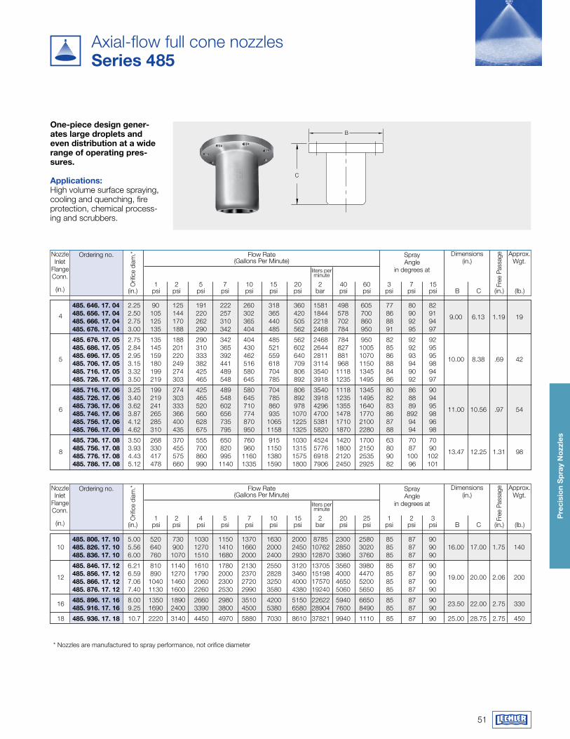
One-piece design gener-ates large droplets and even distribution at a wide range of operating pres-sures.
applications:High volume surface spraying, cooling and quenching, fire protection, chemical process-ing and scrubbers.
Ordering no. Flow Rate(Gallons Per Minute)
Orif
ice
diam
.*
Free
Pas
sage
1 2 5 7 10 15 20 2 40 60 3 7 15 (in.) psi psi psi psi psi psi psi bar psi psi psi psi psi B C (in.) (lb.)
liters per minute
Spray Angle
in degrees at
NozzleInlet
FlangeConn.
(in.)
Approx.Wgt.
Dimensions(in.)
Ordering no. Flow Rate(Gallons Per Minute)
1 2 4 5 7 10 15 2 20 25 1 2 3 (in.) psi psi psi psi psi psi psi bar psi psi psi psi psi B C (in.) (lb.)
liters per minute
Spray Angle
in degrees at
NozzleInlet
FlangeConn.
(in.)
Approx.Wgt.
Dimensions(in.)
485. 806. 17. 10 5.00 520 730 1030 1150 1370 1630 2000 8785 2300 2580 85 87 90 10 485. 826. 17. 10 5.56 640 900 1270 1410 1660 2000 2450 10762 2850 3020 85 87 90 16.00 17.00 1.75 140 485. 836. 17. 10 6.00 760 1070 1510 1680 2000 2400 2930 12870 3360 3760 85 87 90
485. 846. 17. 12 6.21 810 1140 1610 1780 2130 2550 3120 13705 3560 3980 85 87 90 12 485. 856. 17. 12 6.59 890 1270 1790 2000 2370 2828 3460 15198 4000 4470 85 87 90 19.00 20.00 2.06 200 485. 866. 17. 12 7.06 1040 1460 2060 2300 2720 3250 4000 17570 4650 5200 85 87 90 485. 876. 17. 12 7.40 1130 1600 2260 2530 2990 3580 4380 19240 5060 5650 85 87 90
16 485. 896. 17. 16 8.00 1350 1890 2660 2980 3510 4200 5150 22622 5940 6650 85 87 90 23.50 22.00 2.75 330 485. 916. 17. 16 9.25 1690 2400 3390 3800 4500 5380 6580 28904 7600 8490 85 87 90
18 485. 936. 17. 18 10.7 2220 3140 4450 4970 5880 7030 8610 37821 9940 1110 85 87 90 25.00 28.75 2.75 450
Orif
ice
diam
.*
Free
Pas
sage
485. 646. 17. 04 2.25 90 125 191 222 260 318 360 1581 498 605 77 80 82 4 485. 656. 17. 04 2.50 105 144 220 257 302 365 420 1844 578 700 86 90 91 9.00 6.13 1.19 19 485. 666. 17. 04 2.75 125 170 262 310 365 440 505 2218 702 860 88 92 94 485. 676. 17. 04 3.00 135 188 290 342 404 485 562 2468 784 950 91 95 97
485. 676. 17. 05 2.75 135 188 290 342 404 485 562 2468 784 950 82 92 92 485. 686. 17. 05 2.84 145 201 310 365 430 521 602 2644 827 1005 85 92 95 5 485. 696. 17. 05 2.95 159 220 333 392 462 559 640 2811 881 1070 86 93 95 10.00 8.38 .69 42 485. 706. 17. 05 3.15 180 249 382 441 516 618 709 3114 968 1150 88 94 98 485. 716. 17. 05 3.32 199 274 425 489 580 704 806 3540 1118 1345 84 90 94 485. 726. 17. 05 3.50 219 303 465 548 645 785 892 3918 1235 1495 86 92 97
485. 716. 17. 06 3.25 199 274 425 489 580 704 806 3540 1118 1345 80 86 90 485. 726. 17. 06 3.40 219 303 465 548 645 785 892 3918 1235 1495 82 88 94 6 485. 736. 17. 06 3.62 241 333 520 602 710 860 978 4296 1355 1640 83 89 95 11.00 10.56 .97 54 485. 746. 17. 06 3.87 265 366 560 656 774 935 1070 4700 1478 1770 86 892 98 485. 756. 17. 06 4.12 285 400 628 735 870 1065 1225 5381 1710 2100 87 94 96 485. 766. 17. 06 4.62 310 435 675 795 950 1158 1325 5820 1870 2280 88 94 98
485. 736. 17. 08 3.50 268 370 555 650 760 915 1030 4524 1420 1700 63 70 70 8 485. 756. 17. 08 3.93 330 455 700 820 960 1150 1315 5776 1800 2150 80 87 90 13.47 12.25 1.31 98 485. 776. 17. 08 4.43 417 575 860 995 1160 1380 1575 6918 2120 2535 90 100 102 485. 786. 17. 08 5.12 478 660 990 1140 1335 1590 1800 7906 2450 2925 82 96 101
* Nozzles are manufactured to spray performance, not orifice diameter
52
Pre
cisi
on
Sp
ray
Noz
zles
Conversion formula for the above series: v.
2 = v.
1 *p2 p1
( )0.4
Hex
D
L1
L2
G
D
Flats
L1
L2
G G
D2
Hex
D1
L2
L1
Code Ba-Bg
Code Bk
Code Bm
Spray angle
Ordering no.
Orifi
ce d
iam
.
Free
pas
sage
Flow Rate(Gallons Per Minute)
Spray Diam. D (in.) @ 30 psi
H
DType
Mat. no. Conection
PVD
F
Poly
pro
Male NPT
10 psi
20 psi
liters per minute
2 bar 30 psi
40psi
60psi
80psi
100psi
150psi
5E 53 ⅛" ¼" ⅜" ½" ¾" 1" (in) (in) H = 8" H =20"
60° 460. 644 - - BC BE - - - .095 .075 .69 .91 4.0 1.1 1.2 1.4 1.6 1.7 2.0 9 22460. 964 - - - - - Bk - .229 .193 4.3 5.7 25 6.7 7.5 8.8 9.9 10.8 12.7 9 22
90° 460. 326 - Ba - - - - - .032 .022 .07 .09 0.4 .11 .12 .14 .16 .17 .20 15 34460. 406 - Ba - - - - - .047 .033 .17 .23 1.0 .27 .30 .35 .40 .43 .51 15 34460. 486 - Ba - - - - - .057 .047 .28 .36 1.6 .43 .48 .57 .63 .69 .82 15 34460. 526 - Ba - - - - - .065 .051 .35 .46 2.0 .54 .60 .71 .79 .87 1.0 15 34460. 606 - Ba - BE - - - .081 .057 .54 .72 3.2 .84 .95 1.1 1.2 1.4 1.6 15 34460.646 - - BC BE - - - .091 .071 .69 .91 4.0 1.1 1.2 1.4 1.6 1.7 2.0 15 38460.726 - - - BE - - - .116 .079 1.1 1.4 6.3 1.7 1.9 2.2 2.5 2.7 3.2 15 38460.746 - - - BE - - - .130 .075 1.2 1.6 7.1 1.9 2.1 2.5 2.8 3.1 3.6 15 38460.766 - - - BE - - - .130 .095 1.4 1.8 8.0 2.1 2.4 2.8 3.2 3.5 4.1 15 38460.806 - - - BE - - - .146 .106 1.7 2.3 10.0 2.7 3.0 3.5 4.0 4.3 5.1 15 38460.846 - - - BE - - - .160 .126 2.2 2.8 12.5 3.3 3.8 4.4 5.0 5.4 6.4 15 38460.886 - - - BE Bg - - .185 .122 2.8 3.6 16.0 4.3 4.8 5.7 6.3 6.9 8.2 15 38460.926 - - - - Bg - - .205 .150 3.5 4.6 20 5.4 6.0 7.1 7.9 8.7 10.2 15 38460.966 - - - - Bg Bk - .229 .150 4.3 5.7 25 6.7 7.5 8.8 9.9 10.8 12.7 15 38461.006 - - - - Bg - - .252 .150 5.4 7.2 32 8.4 9.5 11.1 12.5 13.7 16.1 15 38461.046 - - - - Bk - .284 .209 6.9 9.1 40 10.7 12.0 14.1 15.9 17.3 20 15 38461. 086 - - - - - Bk - .323 .209 8.6 11.4 50 13.4 15.0 17.7 19.8 22 25 15 38461. 126 - - - - - - Bm .366 .256 10.9 14.3 63 16.9 18.9 22 25 27 32 15 38461.146 - - - - - - Bm .390 .264 12.3 16.2 71 19.0 21 25 28 31 36 15 38
very uniform spray pattern. applications:Cleaning and washing pro-cess, cooling of gaseous fluids and solids, surface spraying, spraying onto mats in air washers, improving of chemi-cal reactions.
Continued on next page.
Subject to technical modifications.Please enquire about the exact dimensions if the installation situationis critical!
Example Type + material no. + Code = Ordering no. for ordering: 460.326 + 5E + Ba = 460.326.5E.Ba
Codedimensions [in]
G L1 L2 D1 D2 Hex/Flats
Ba 1/8 NPT .87 .26 .51 - 9/16BC 1/4 NPT .87 .38 .51 - 9/16BE 3/8 NPT 1.18 .39 .67 - 11/16Bg 1/2 NPT 1.71 .52 .87 - 7/8Bk 3/4 NPT 1.65 .59 1.24 - 1-1/8Bm 1 NPT 2.07 .59 1.06 1.36 1-3/8
Axial-flow full cone nozzlesSeries 460 / 461
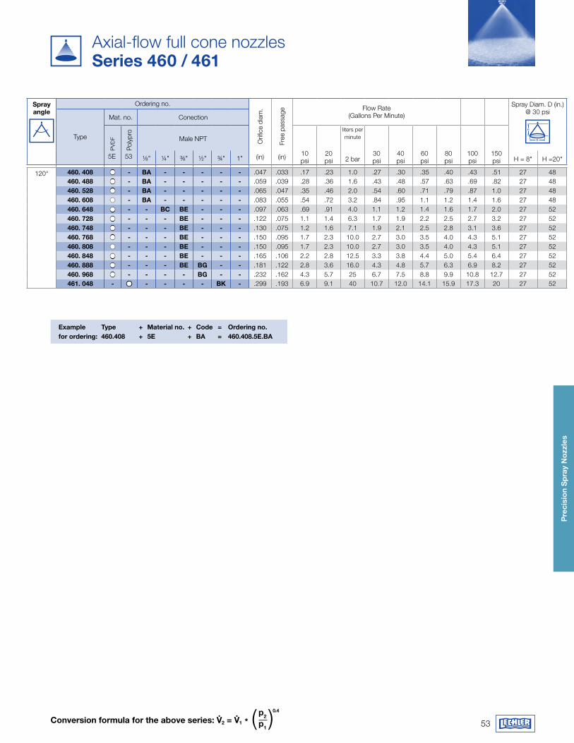
53
Pre
cisi
on
Sp
ray
Noz
zles
Conversion formula for the above series: v.
2 = v.
1 *p2 p1
( )0.4
Example Type + material no. + Code = Ordering no. for ordering: 460.408 + 5E + Ba = 460.408.5E.Ba
Spray angle
Ordering no.
Orifi
ce d
iam
.
Free
pas
sage
Flow Rate(Gallons Per Minute)
Spray Diam. D (in.) @ 30 psi
H
DType
Mat. no. ConectionP
VDF
Poly
pro
Male NPT
10 psi
20 psi
liters per minute
30 psi
40psi
60psi
80psi
100psi
150psi
5E 53 ⅛" ¼" ⅜" ½" ¾" 1" (in) (in) 2 bar H = 8" H =20"
120° 460. 408 - Ba - - - - - .047 .033 .17 .23 1.0 .27 .30 .35 .40 .43 .51 27 48460. 488 - Ba - - - - - .059 .039 .28 .36 1.6 .43 .48 .57 .63 .69 .82 27 48460. 528 - Ba - - - - - .065 .047 .35 .46 2.0 .54 .60 .71 .79 .87 1.0 27 48460. 608 - Ba - - - - - .083 .055 .54 .72 3.2 .84 .95 1.1 1.2 1.4 1.6 27 48460. 648 - - BC BE - - - .097 .063 .69 .91 4.0 1.1 1.2 1.4 1.6 1.7 2.0 27 52460. 728 - - - BE - - - .122 .075 1.1 1.4 6.3 1.7 1.9 2.2 2.5 2.7 3.2 27 52460. 748 - - - BE - - - .130 .075 1.2 1.6 7.1 1.9 2.1 2.5 2.8 3.1 3.6 27 52460. 768 - - - BE - - - .150 .095 1.7 2.3 10.0 2.7 3.0 3.5 4.0 4.3 5.1 27 52460. 808 - - - BE - - - .150 .095 1.7 2.3 10.0 2.7 3.0 3.5 4.0 4.3 5.1 27 52460. 848 - - - BE - - - .165 .106 2.2 2.8 12.5 3.3 3.8 4.4 5.0 5.4 6.4 27 52460. 888 - - - BE Bg - - .181 .122 2.8 3.6 16.0 4.3 4.8 5.7 6.3 6.9 8.2 27 52460. 968 - - - - Bg - - .232 .162 4.3 5.7 25 6.7 7.5 8.8 9.9 10.8 12.7 27 52461. 048 - - - - - Bk - .299 .193 6.9 9.1 40 10.7 12.0 14.1 15.9 17.3 20 27 52
Axial-flow full cone nozzlesSeries 460 / 461
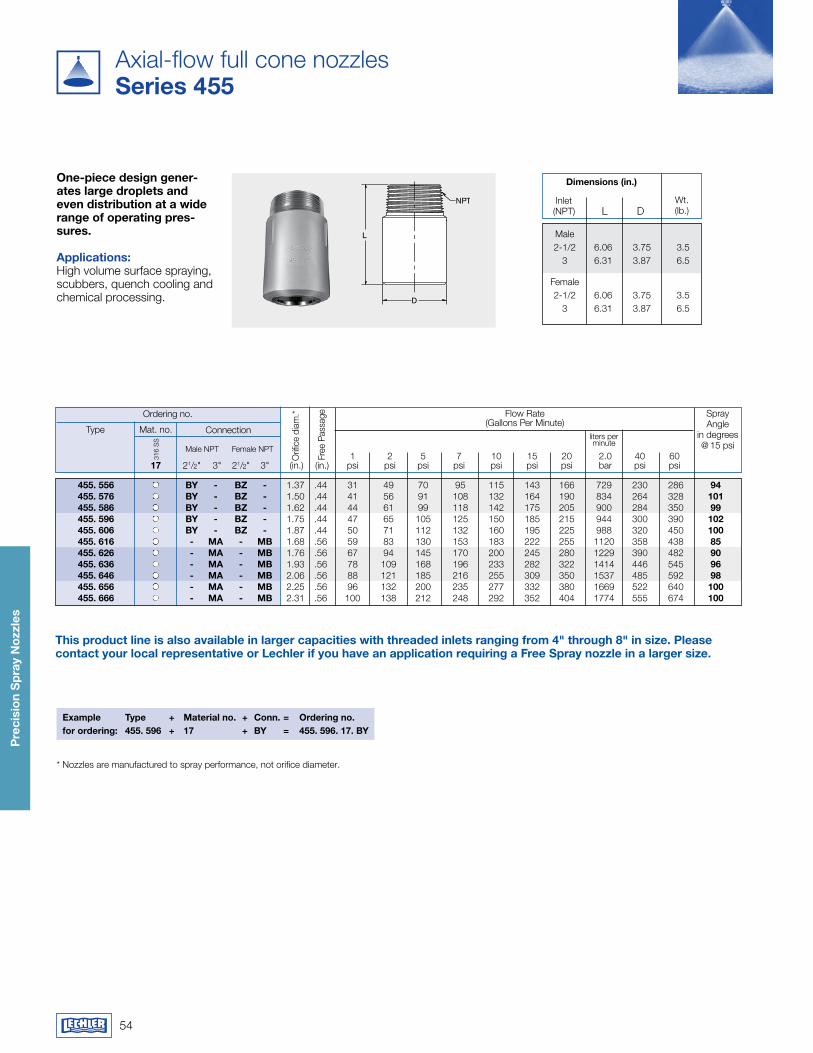
54
Pre
cisi
on
Sp
ray
Noz
zles
Axial-flow full cone nozzlesSeries 455
One-piece design gener-ates large droplets and even distribution at a wide range of operating pres-sures. applications:High volume surface spraying, scubbers, quench cooling and chemical processing.
Ordering no. Flow Rate(Gallons Per Minute)
Mat. no.
316
SS
Orif
ice
diam
.*
Connection
Male NPT Female NPT
Free
Pas
sage
1 2 5 7 10 15 20 2.0 40 60 17 21/2" 3" 21/2" 3" (in.) (in.) psi psi psi psi psi psi psi bar psi psi
Typeliters per minute
455. 556 By - Bz - 1.37 .44 31 49 70 95 115 143 166 729 230 286 94 455. 576 By - Bz - 1.50 .44 41 56 91 108 132 164 190 834 264 328 101 455. 586 By - Bz - 1.62 .44 44 61 99 118 142 175 205 900 284 350 99 455. 596 By - Bz - 1.75 .44 47 65 105 125 150 185 215 944 300 390 102 455. 606 By - Bz - 1.87 .44 50 71 112 132 160 195 225 988 320 450 100 455. 616 - ma - mB 1.68 .56 59 83 130 153 183 222 255 1120 358 438 85 455. 626 - ma - mB 1.76 .56 67 94 145 170 200 245 280 1229 390 482 90 455. 636 - ma - mB 1.93 .56 78 109 168 196 233 282 322 1414 446 545 96 455. 646 - ma - mB 2.06 .56 88 121 185 216 255 309 350 1537 485 592 98 455. 656 - ma - mB 2.25 .56 96 132 200 235 277 332 380 1669 522 640 100 455. 666 - ma - mB 2.31 .56 100 138 212 248 292 352 404 1774 555 674 100
Example Type + material no. + Conn. = Ordering no.for ordering: 455. 596 + 17 + By = 455. 596. 17. By
Spray Angle
in degrees @ 15 psi
This product line is also available in larger capacities with threaded inlets ranging from 4" through 8" in size. Please contact your local representative or Lechler if you have an application requiring a free Spray nozzle in a larger size.
dimensions (in.)
L D Inlet(NPT)
Wt.(lb.)
Male 2-1/2 6.06 3.75 3.5 3 6.31 3.87 6.5
Female 2-1/2 6.06 3.75 3.5 3 6.31 3.87 6.5
* Nozzles are manufactured to spray performance, not orifice diameter.
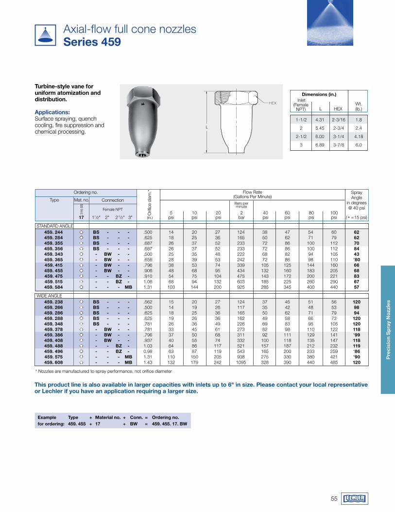
55
Pre
cisi
on
Sp
ray
Noz
zles
Axial-flow full cone nozzlesSeries 459
L
Turbine-style vane for uniform atomization and distribution.
applications:Surface spraying, quench cooling, fire suppression and chemical processing.
Ordering no. Flow Rate(Gallons Per Minute)
Mat. no.
316
SS liters per
minute
Orif
ice
diam
.*
Connection
Female NPT
This product line is also available in larger capacities with inlets up to 6" in size. Please contact your local representative or Lechler if you have an application requiring a larger size.
Example Type + material no. + Conn. = Ordering no.for ordering: 459. 455 + 17 + Bw = 459. 455. 17. Bw
Type
Spray Angle
in degrees @ 40 psi
5 10 20 2 40 60 80 100 17 11/2" 2" 21/2" 3" (in.) psi psi psi bar psi psi psi psi (* =15 psi)
STANDARD ANGLE 459. 244 BS - - - .500 14 20 27 124 38 47 54 60 62 459. 284 BS - - - .625 18 25 36 165 50 62 71 79 62 459. 355 BS - - - .687 26 37 52 233 72 86 100 112 70 459. 356 BS - - - .687 26 37 52 233 72 86 100 112 84 459. 343 - Bw - - .500 25 35 48 222 68 82 94 105 43 459. 365 - Bw - - .656 28 39 53 242 72 86 98 110 *80 459. 415 - Bw - - .796 38 53 74 339 105 125 144 160 66 459. 455 - Bw - - .906 48 68 95 434 132 160 183 205 68 459. 475 - - Bz - .910 54 75 104 475 143 172 200 221 83 459. 515 - - Bz - 1.06 68 94 132 603 185 225 260 290 67 459. 584 - - - mB 1.31 103 144 200 925 285 345 400 440 57
WIDE ANGLE 459. 238 BS - - - .562 15 20 27 124 37 45 51 56 120 459. 266 BS - - - .500 14 19 26 117 35 42 48 53 98 459. 286 BS - - - .625 18 25 36 165 50 62 71 79 94 459. 288 BS - - - .625 19 26 36 162 49 58 66 73 120 459. 348 BS - - - .781 26 36 49 226 69 83 95 105 120 459. 378 - Bw - - .781 33 45 61 273 82 98 110 122 118 459. 386 - Bw - - .796 37 50 68 311 92 111 129 141 *99 459. 408 - Bw - - .937 40 55 74 332 100 118 135 147 118 459. 488 - - Bz - 1.03 64 86 117 521 157 187 212 232 119 459. 496 - - Bz - 0.98 63 87 119 543 165 200 233 259 *86 459. 575 - - - mB 1.31 110 150 205 938 275 330 380 421 *90 459. 608 - - - mB 1.43 132 179 242 1095 328 390 440 485 120
dimensions (in.)
L HEX
Inlet(Female
NPT)Wt.(lb.)
1-1/2 4.31 2-3/16 1.8
2 5.45 2-3/4 2.4
2-1/2 6.00 3-1/4 4.18
3 6.89 3-7/8 6.0
* Nozzles are manufactured to spray performance, not orifice diameter
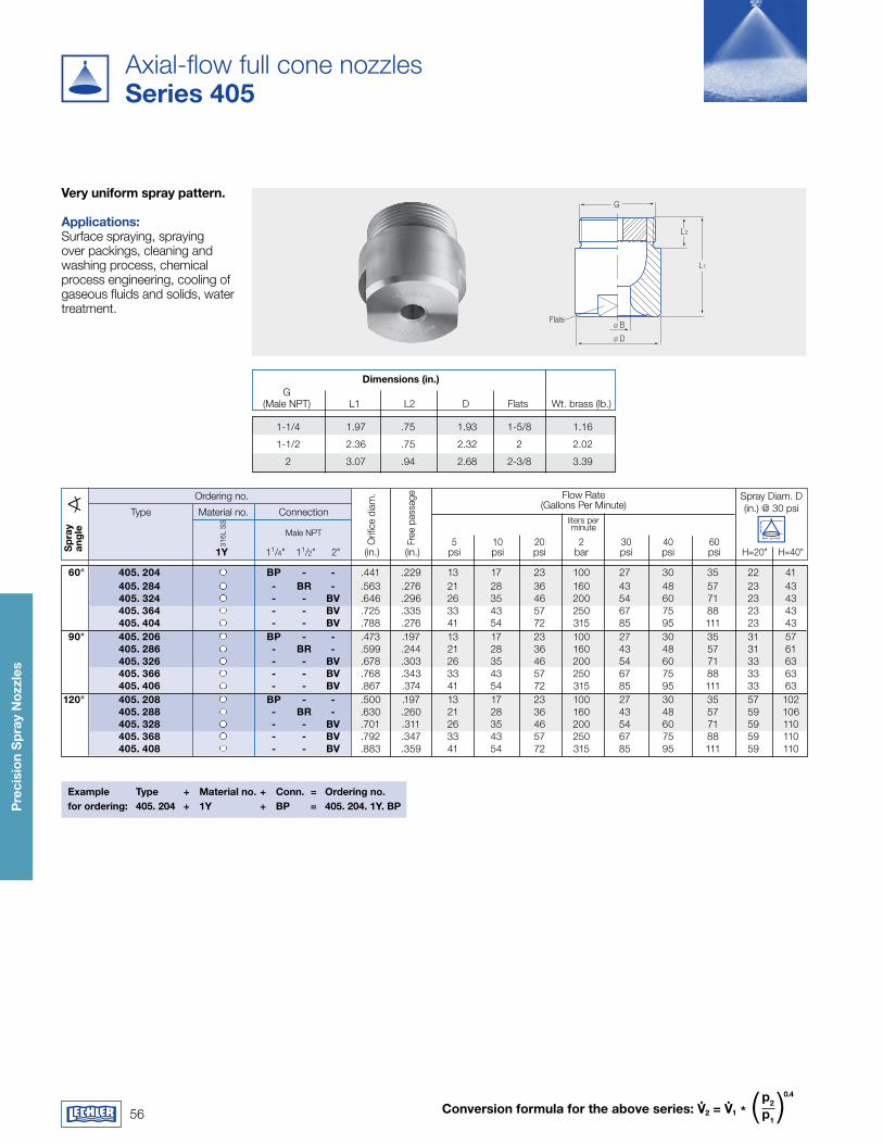
56
Pre
cisi
on
Sp
ray
Noz
zles
Conversion formula for the above series: v.
2 = v.
1 *p2 p1
( )0.4
G
L2
L1
Ø D
Ø BFlats
Sp
ray
ang
leS
pra
y an
gle
Axial-flow full cone nozzlesSeries 405
very uniform spray pattern.
applications:Surface spraying, spraying over packings, cleaning and washing process, chemical process engineering, cooling of gaseous fluids and solids, water treatment.
dimensions (in.) G (Male NPT) L1 L2 D Flats Wt. brass (lb.)
1-1/4 1.97 .75 1.93 1-5/8 1.16
1-1/2 2.36 .75 2.32 2 2.02
2 3.07 .94 2.68 2-3/8 3.39
Ordering no. Flow Rate(Gallons Per Minute)
Material no.
316L
SS
Free
pas
sage
5 10 20 2 30 40 60 1y 11/4" 11/2" 2" (in.) (in.) psi psi psi bar psi psi psi H=20" H=40"
Spray Diam. D(in.) @ 30 psi
Example Type + material no. + Conn. = Ordering no.for ordering: 405. 204 + 1y + BP = 405. 204. 1y. BP
Connection
Male NPT
Orif
ice
diam
.
Typeliters per minute
60° 405. 204 BP - - .441 .229 13 17 23 100 27 30 35 22 41 405. 284 - Br - .563 .276 21 28 36 160 43 48 57 23 43 405. 324 - - Bv .646 .296 26 35 46 200 54 60 71 23 43 405. 364 - - Bv .725 .335 33 43 57 250 67 75 88 23 43 405. 404 - - Bv .788 .276 41 54 72 315 85 95 111 23 43 90° 405. 206 BP - - .473 .197 13 17 23 100 27 30 35 31 57 405. 286 - Br - .599 .244 21 28 36 160 43 48 57 31 61 405. 326 - - Bv .678 .303 26 35 46 200 54 60 71 33 63 405. 366 - - Bv .768 .343 33 43 57 250 67 75 88 33 63 405. 406 - - Bv .867 .374 41 54 72 315 85 95 111 33 63 120° 405. 208 BP - - .500 .197 13 17 23 100 27 30 35 57 102 405. 288 - Br - .630 .260 21 28 36 160 43 48 57 59 106 405. 328 - - Bv .701 .311 26 35 46 200 54 60 71 59 110 405. 368 - - Bv .792 .347 33 43 57 250 67 75 88 59 110 405. 408 - - Bv .883 .359 41 54 72 315 85 95 111 59 110
H
D
Sp
ray
ang
le
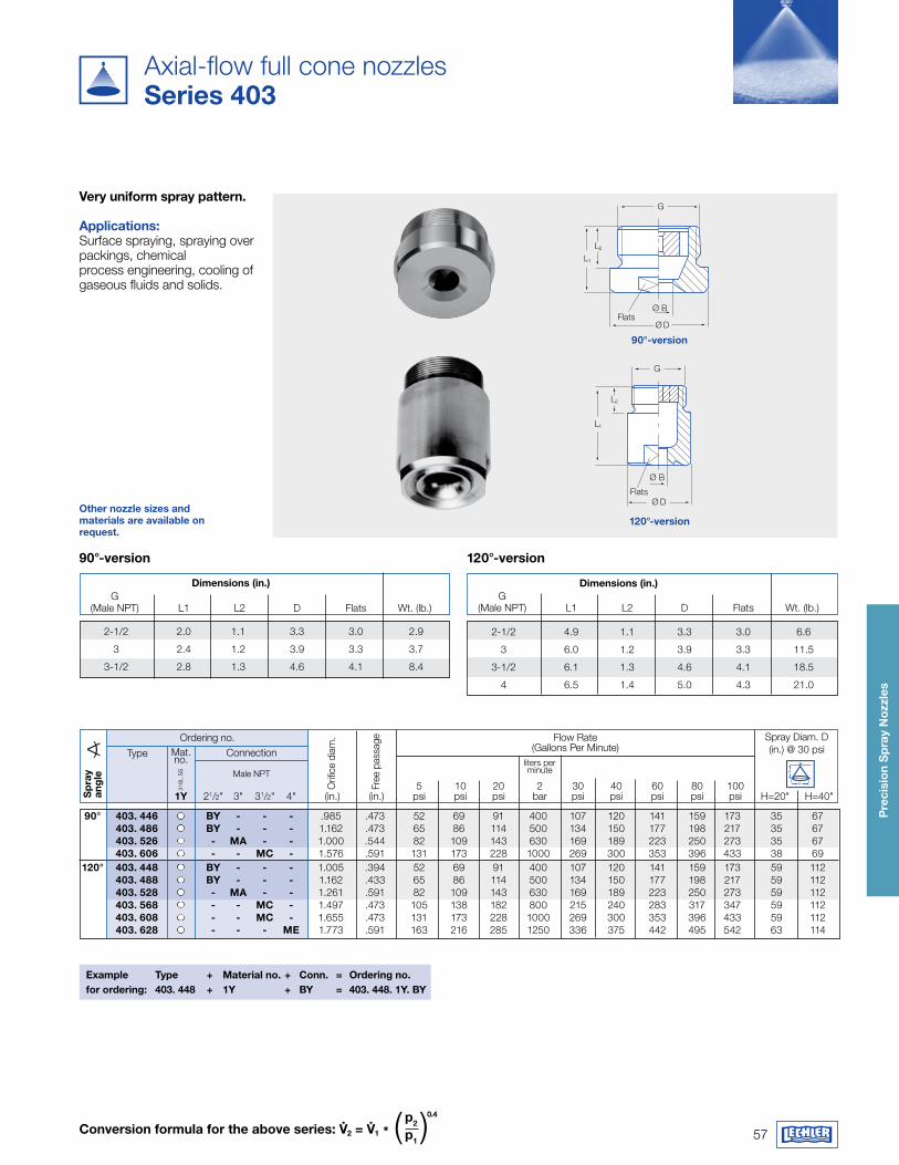
57
Pre
cisi
on
Sp
ray
Noz
zles
Other nozzle sizes andmaterials are available onrequest.
Conversion formula for the above series: v.
2 = v.
1 *p2 p1
( )0.4
dimensions (in.) G (Male NPT) L1 L2 D Flats Wt. (lb.)
2-1/2 2.0 1.1 3.3 3.0 2.9
3 2.4 1.2 3.9 3.3 3.7
3-1/2 2.8 1.3 4.6 4.1 8.4
dimensions (in.)
2-1/2 4.9 1.1 3.3 3.0 6.6
3 6.0 1.2 3.9 3.3 11.5
3-1/2 6.1 1.3 4.6 4.1 18.5
4 6.5 1.4 5.0 4.3 21.0
G (Male NPT) L1 L2 D Flats Wt. (lb.)
Ordering no. Flow Rate(Gallons Per Minute)Mat.
no.
316L
SS
liters per minute
Orif
ice
diam
.
Connection
Male NPT
Free
pas
sage
Type
Sp
ray
ang
le
Example Type + material no. + Conn. = Ordering no.for ordering: 403. 448 + 1y + By = 403. 448. 1y. By
Spray Diam. D(in.) @ 30 psi
5 10 20 2 30 40 60 80 100 1y 21/2" 3" 31/2" 4" (in.) (in.) psi psi psi bar psi psi psi psi psi H=20" H=40"
90° 403. 446 By - - - .985 .473 52 69 91 400 107 120 141 159 173 35 67 403. 486 By - - - 1.162 .473 65 86 114 500 134 150 177 198 217 35 67 403. 526 - ma - - 1.000 .544 82 109 143 630 169 189 223 250 273 35 67 403. 606 - - mC - 1.576 .591 131 173 228 1000 269 300 353 396 433 38 69 120° 403. 448 By - - - 1.005 .394 52 69 91 400 107 120 141 159 173 59 112 403. 488 By - - - 1.162 .433 65 86 114 500 134 150 177 198 217 59 112 403. 528 - ma - - 1.261 .591 82 109 143 630 169 189 223 250 273 59 112 403. 568 - - mC - 1.497 .473 105 138 182 800 215 240 283 317 347 59 112 403. 608 - - mC - 1.655 .473 131 173 228 1000 269 300 353 396 433 59 112 403. 628 - - - mE 1.773 .591 163 216 285 1250 336 375 442 495 542 63 114
H
D
FlatsØ B
Ø D
L1
L2
G
Flats
Ø B
Ø D
L1
L2
G
90°-version
120°-version
120°-version90°-version
Axial-flow full cone nozzlesSeries 403
very uniform spray pattern. applications: Surface spraying, spraying over packings, chemical process engineering, cooling of gaseous fluids and solids.
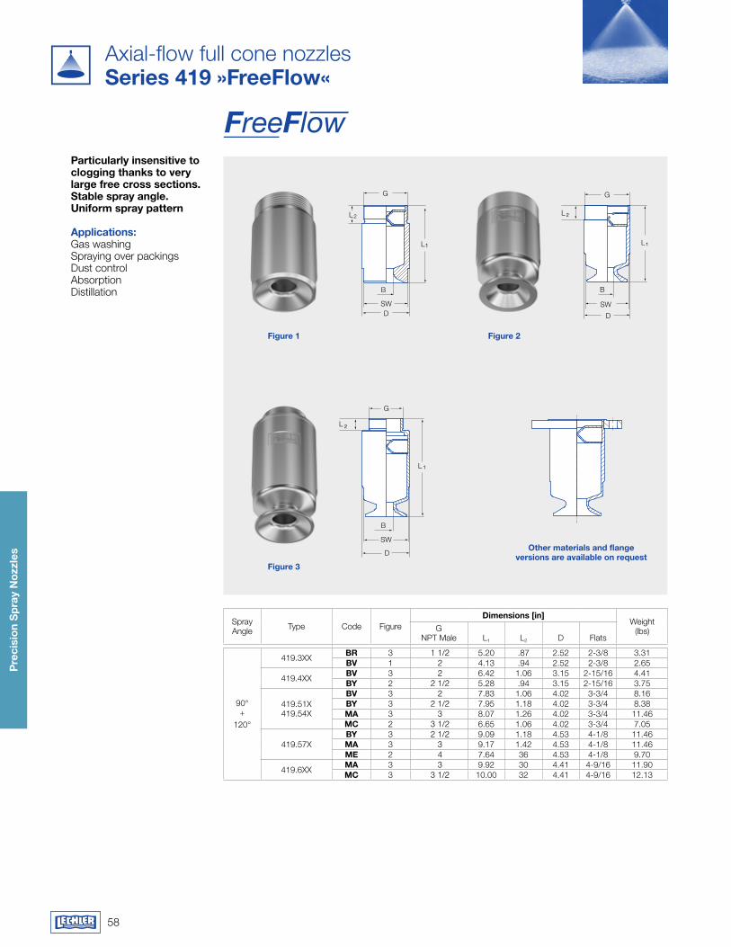
58
Pre
cisi
on
Sp
ray
Noz
zles
Axial-flow full cone nozzlesSeries 419 »freeflow«
Particularly insensitive to clogging thanks to very large free cross sections. Stable spray angle. Uniform spray pattern
applications: Gas washingSpraying over packingsDust controlAbsorptionDistillation
Spray Angle Type Code Figure
dimensions [in]Weight
(lbs)GNPT Male L1 L2 D Flats
90° +
120°
419.3XX Br 3 1 1/2 5.20 .87 2.52 2-3/8 3.31Bv 1 2 4.13 .94 2.52 2-3/8 2.65
419.4XX Bv 3 2 6.42 1.06 3.15 2-15/16 4.41By 2 2 1/2 5.28 .94 3.15 2-15/16 3.75
419.51X419.54X
Bv 3 2 7.83 1.06 4.02 3-3/4 8.16By 3 2 1/2 7.95 1.18 4.02 3-3/4 8.38ma 3 3 8.07 1.26 4.02 3-3/4 11.46mC 2 3 1/2 6.65 1.06 4.02 3-3/4 7.05
419.57XBy 3 2 1/2 9.09 1.18 4.53 4-1/8 11.46ma 3 3 9.17 1.42 4.53 4-1/8 11.46mE 2 4 7.64 36 4.53 4-1/8 9.70
419.6XX ma 3 3 9.92 30 4.41 4-9/16 11.90mC 3 3 1/2 10.00 32 4.41 4-9/16 12.13
L1
L2
G
SWD
B
figure 1 figure 2
figure 3
L
L
G
SW
D
B
1
2
L
L
G
SW
D
B
1
2
other materials and flange versions are available on request
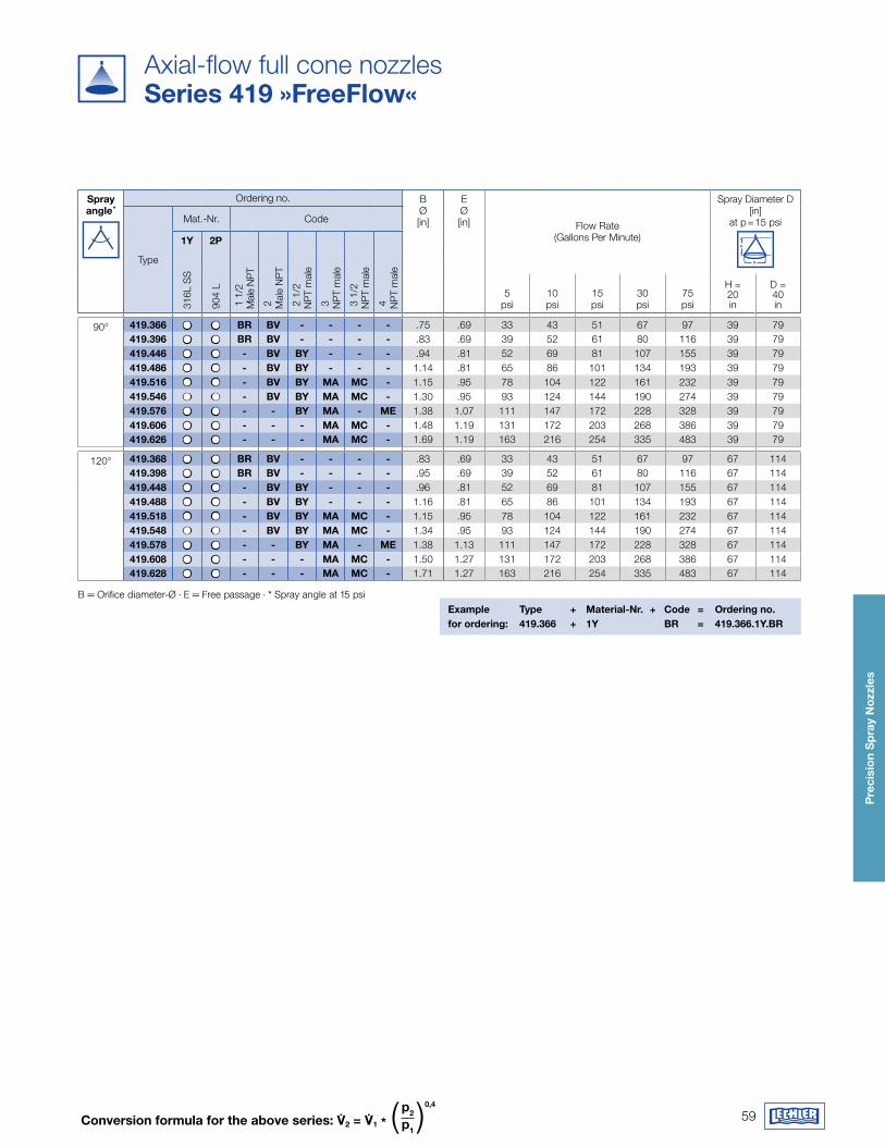
59
Pre
cisi
on
Sp
ray
Noz
zles
Example Type + material-Nr. + Code = Ordering no. for ordering: 419.366 + 1y Br = 419.366.1y.Br
Conversion formula for the above series: 2 = 1 *p2 p1
( )0,4
Axial-flow full cone nozzlesSeries 419 »freeflow«
Spray angle *
Ordering no. BØ[in]
EØ[in] Flow Rate
(Gallons Per Minute)
Spray Diameter D [in]
at p = 15 psi
H
DType
Mat.-Nr. Code
1y 2P
2
Mal
e N
PT
2 1
/2
NP
T m
ale
3
NP
T m
ale
3 1
/2
NP
T m
ale
4
NP
T m
ale
316L
SS
904
L
1 1
/2
Mal
e N
PT
5psi
10psi
15psi
30psi
75psi
H = 20 in
D = 40 in
90° 419.366 Br Bv - - - - .75 .69 33 43 51 67 97 39 79419.396 Br Bv - - - - .83 .69 39 52 61 80 116 39 79419.446 - Bv By - - - .94 .81 52 69 81 107 155 39 79419.486 - Bv By - - - 1.14 .81 65 86 101 134 193 39 79419.516 - Bv By ma mC - 1.15 .95 78 104 122 161 232 39 79419.546 - Bv By ma mC - 1.30 .95 93 124 144 190 274 39 79419.576 - - By ma - mE 1.38 1.07 111 147 172 228 328 39 79419.606 - - - ma mC - 1.48 1.19 131 172 203 268 386 39 79419.626 - - - ma mC - 1.69 1.19 163 216 254 335 483 39 79
120° 419.368 Br Bv - - - - .83 .69 33 43 51 67 97 67 114419.398 Br Bv - - - - .95 .69 39 52 61 80 116 67 114419.448 - Bv By - - - .96 .81 52 69 81 107 155 67 114419.488 - Bv By - - - 1.16 .81 65 86 101 134 193 67 114419.518 - Bv By ma mC - 1.15 .95 78 104 122 161 232 67 114419.548 - Bv By ma mC - 1.34 .95 93 124 144 190 274 67 114419.578 - - By ma - mE 1.38 1.13 111 147 172 228 328 67 114419.608 - - - ma mC - 1.50 1.27 131 172 203 268 386 67 114419.628 - - - ma mC - 1.71 1.27 163 216 254 335 483 67 114
B = Orifice diameter-Ø · E = Free passage · * Spray angle at 15 psi
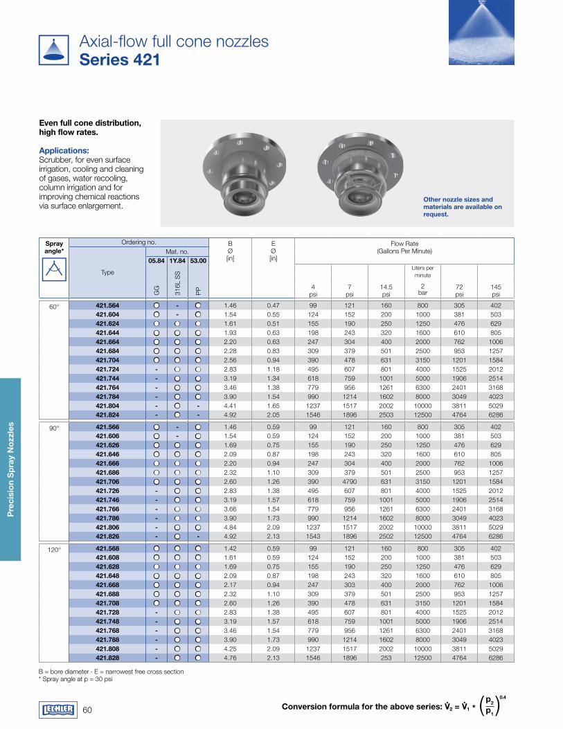
60
Pre
cisi
on
Sp
ray
Noz
zles
Conversion formula for the above series: v.
2 = v.
1 *p2 p1
( )0.4
Other nozzle sizes and materials are available on request.
Axial-flow full cone nozzlesSeries 421
B = bore diameter · E = narrowest free cross section * Spray angle at p = 30 psi
Spray angle*
Ordering no. BØ[in]
EØ[in]
Flow Rate(Gallons Per Minute)
Type
Mat. no.05.84 1y.84 53.00
GG
316L
SS
PP 4
psi7
psi14.5psi
Liters per minute
72 psi
145 psi
2bar
60° 421.564 - 1.46 0.47 99 121 160 800 305 402421.604 - 1.54 0.55 124 152 200 1000 381 503421.624 1.61 0.51 155 190 250 1250 476 629421.644 1.93 0.63 198 243 320 1600 610 805421.664 2.20 0.63 247 304 400 2000 762 1006421.684 2.28 0.83 309 379 501 2500 953 1257421.704 2.56 0.94 390 478 631 3150 1201 1584421.724 - 2.83 1.18 495 607 801 4000 1525 2012421.744 - 3.19 1.34 618 759 1001 5000 1906 2514421.764 - 3.46 1.38 779 956 1261 6300 2401 3168421.784 - 3.90 1.54 990 1214 1602 8000 3049 4023421.804 - - 4.41 1.65 1237 1517 2002 10000 3811 5029421.824 - - 4.92 2.05 1546 1896 2503 12500 4764 6286
90° 421.566 - 1.46 0.59 99 121 160 800 305 402421.606 - 1.54 0.59 124 152 200 1000 381 503421.626 1.69 0.75 155 190 250 1250 476 629421.646 2.09 0.87 198 243 320 1600 610 805421.666 2.20 0.94 247 304 400 2000 762 1006421.686 2.32 1.10 309 379 501 2500 953 1257421.706 2.60 1.26 390 4790 631 3150 1201 1584421.726 - 2.83 1.38 495 607 801 4000 1525 2012421.746 - 3.19 1.57 618 759 1001 5000 1906 2514421.766 - 3.66 1.54 779 956 1261 6300 2401 3168421.786 - 3.90 1.73 990 1214 1602 8000 3049 4023421.806 - 4.84 2.09 1237 1517 2002 10000 3811 5029421.826 - - 4.92 2.13 1543 1896 2502 12500 4764 6286
120° 421.568 1.42 0.59 99 121 160 800 305 402421.608 1.61 0.59 124 152 200 1000 381 503421.628 1.69 0.75 155 190 250 1250 476 629421.648 2.09 0.87 198 243 320 1600 610 805421.668 2.17 0.94 247 303 400 2000 762 1006421.688 2.32 1.10 309 379 501 2500 953 1257421.708 2.60 1.26 390 478 631 3150 1201 1584421.728 - 2.83 1.38 495 607 801 4000 1525 2012421.748 - 3.19 1.57 618 759 1001 5000 1906 2514421.768 - 3.46 1.54 779 956 1261 6300 2401 3168421.788 - 3.90 1.73 990 1214 1602 8000 3049 4023421.808 - 4.25 2.09 1237 1517 2002 10000 3811 5029421.828 - 4.76 2.13 1546 1896 253 12500 4764 6286
Even full cone distribution, high flow rates.
applications:Scrubber, for even surface irrigation, cooling and cleaning of gases, water recooling, column irrigation and for improving chemical reactions via surface enlargement.
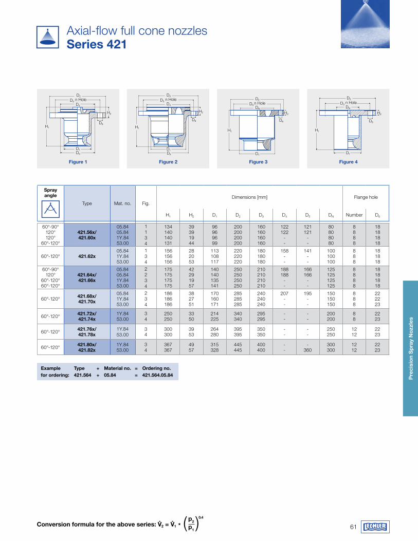
61
Pre
cisi
on
Sp
ray
Noz
zles
D2
D6
D1
H1
H2
D5
D3 n HoleD4
D2
D4
D6
D1
H2
H1
D5
D3 n Hole D2
D6
D1
H2
H1
D3 n HoleDN
D2
D6
H2
H1
D1
DN
D3 n Hole
Conversion formula for the above series: v.
2 = v.
1 *p2 p1
( )0.4
figure 1 figure 2 figure 3 figure 4
Axial-flow full cone nozzlesSeries 421
Example Type + material no. = Ordering no.for ordering: 421.564 + 05.84 = 421.564.05.84
Spray angle
Type Mat. no. Fig.Dimensions [mm] Flange hole
H1 H2 D1 D2 D3 D4 D5 DN Number D6
60°-90°120°120°
60°-120°
421.56x/421.60x
05.8405.841Y.8453.00
1134
134140140131
39391944
96969699
200200200200
160160160160
122122
--
121121
--
80808080
8888
18181818
60°-120° 421.62x05.841Y.8453.00
134
156156156
282053
113108117
220220220
180180180
158--
141--
100 100 100
888
18 18 18
60°-90°120°
60°-120°60°-120°
421.64x/421.66x
05.8405.841Y.8453.00
2234
175175175175
42291957
140140135141
250250250250
210210210210
188188
--
166166
--
125125125125
8888
18181818
60°-120° 421.68x/421.70x
05.841Y.8453.00
234
186186186
382751
170160171
285285285
240240240
207--
195--
150150150
888
222223
60°-120° 421.72x/421.74x
1Y.8453.00
34
250250
3350
214225
340340
295295
--
--
200200
88
2223
60°-120° 421.76x/421.78x
1Y.8453.00
34
300300
3953
264280
395395
350350
--
--
250 250
12 12
2223
60°-120° 421.80x/421.82x
1Y.8453.00
34
367367
4957
315328
445445
400400
--
-360
300300
12 12
2223
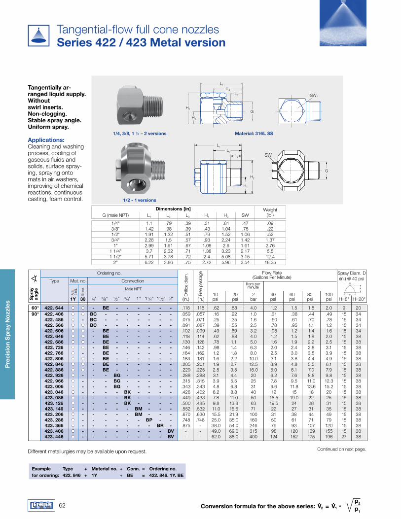
62
Pre
cisi
on
Sp
ray
Noz
zles
Conversion formula for the above series: v.
2 = v.
1 *p2 p1
Tangential-flow full cone nozzles Series 422 / 423 metal version
Tangentially ar-ranged liquid supply. without swirl inserts. Non-clogging. Stable spray angle. Uniform spray. applications:Cleaning and washing process, cooling of gaseous fluids and solids, surface spray-ing, spraying onto mats in air washers, improving of chemical reactions, continuous casting, foam control.
Ordering no. Flow Rate(Gallons Per Minute)
Mat. no.
Orif
ice
diam
.
Bra
ss
Spray Diam. D(in.) @ 40 psiConnection
Free
pas
sage
Type
10 20 2 40 60 80 100 1y 30 1/4" 3/8" 1/2" 3/4" 1" 11/4" 11/2" 2" (in.) (in.) psi psi bar psi psi psi psi H=8" H=20"
liters per minute
Different metallurgies may be available upon request.
Sp
ray
ang
le H
D
Male NPT
Continued on next page.
AIS
I 31
6L
Example Type + material no. + Conn. = Ordering no.for ordering: 422. 846 + 1y + BE = 422. 846. 1y. BE
60° 422. 644 - BE - - - - - - .118 .118 .62 .88 4.0 1.2 1.5 1.8 2.0 9 20 90° 422. 406 BC - - - - - - - .059 .057 .16 .22 1.0 .31 .38 .44 .49 15 34 422. 486 - BC - - - - - - - .075 .071 .25 .35 1.6 .50 .61 .70 .78 15 34 422. 566 BC - - - - - - - .091 .087 .39 .55 2.5 .78 .95 1.1 1.2 15 34 422. 606 - BE - - - - - - .102 .099 .49 .69 3.2 .98 1.2 1.4 1.6 15 34 422. 646 - BE - - - - - - .118 .114 .62 .88 4.0 1.2 1.5 1.8 2.0 15 38 422. 686 - BE - - - - - - .130 .126 .78 1.1 5.0 1.6 1.9 2.2 2.5 15 38 422. 726 - BE - - - - - - .146 .142 .98 1.4 6.3 2.0 2.4 2.8 3.1 15 38 422. 766 - - BE - - - - - - .164 .162 1.2 1.8 8.0 2.5 3.0 3.5 3.9 15 38 422. 806 - BE - - - - - - .183 .181 1.6 2.2 10.0 3.1 3.8 4.4 4.9 15 38 422. 846 - BE - - - - - - .205 .201 1.9 2.7 12.5 3.9 4.8 5.5 6.1 15 38 422. 886 - BE - - - - - - .229 .225 2.5 3.5 16.0 5.0 6.1 7.0 7.9 15 38 422. 926 - - - Bg - - - - - .288 .288 3.1 4.4 20 6.2 7.6 8.8 9.8 15 38 422. 966 - - - Bg - - - - - .315 .315 3.9 5.5 25 7.8 9.5 11.0 12.3 15 38 423. 006 - - - Bg - - - - - .343 .343 4.8 6.8 31 9.6 11.8 13.6 15.2 15 38 423. 046 - - - - Bk - - - - .426 .402 6.2 8.8 40 12 15 18 20 15 38 423. 086 - - - - Bk - - - - .449 .433 7.8 11.0 50 15.5 19.0 22 25 15 38 423. 126 - - - - Bk - - - - .500 .485 9.8 13.8 63 19.5 24 28 31 15 38 423. 146 - - - - - Bm - - - .552 .532 11.0 15.6 71 22 27 31 35 15 38 423. 206 - - - - - Bm - - - .670 .630 15.5 21.9 100 31 38 44 49 15 38 423. 286 - - - - - - BP - - .748 .748 25.0 35.0 160 50 61 71 79 15 38 423. 366 - - - - - - - Br - .875 - 38.0 54.0 246 76 93 107 120 15 38 423. 406 - - - - - - - - Bv - - 49.0 69.0 315 98 120 139 155 15 38 423. 446 - - - - - - - - Bv - - 62.0 88.0 400 124 152 175 196 27 38
Hex1
L1
L2
W1
L3
H1
GW2
H2
Hex2
H2
L1
L2
L3
H1
SW 1
G
Hex1L1
L2
L3
H1
G
H2
Hex2
1/4, 3/8, 1 ¼ – 2 versions
1/2 - 1 versions
material: 316L SS
dimensions [in] Weight (lb.)G (male NPT) L1 L2 L3 H1 H2 SW
1/4" 1.1 .79 .39 .31 .81 .47 .093/8" 1.42 .98 .39 .43 1.04 .75 .221/2" 1.91 1.32 .51 .79 1.52 1.06 .523/4" 2.28 1.5 .57 .93 2.24 1.42 1.371" 2.99 1.91 .67 1.08 2.6 1.61 2.76
1 1/4" 3.7 2.32 .71 1.38 3.23 2.17 5.51 1/2" 5.71 3.78 .72 2.4 5.08 3.15 12.4
2" 6.22 3.86 .75 2.72 5.96 3.54 18.35
SW
H2
L1
L2
L3
H1
SW 1
G
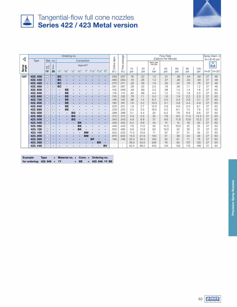
63
Pre
cisi
on
Sp
ray
Noz
zles
Tangential-flow full cone nozzles Series 422 / 423 metal version
Ordering no. Flow Rate(Gallons Per Minute)
Mat. no.
Orif
ice
diam
.
Bra
ss
Spray Diam. D(in.) @ 40 psiConnection
Free
pas
sage
Type
10 20 2 40 60 80 100 1y 30 1/4" 3/8" 1/2" 3/4" 1" 11/4" 11/2" 2" (in.) (in.) psi psi bar psi psi psi psi H=8" H=20"
liters per minute
Sp
ray
ang
le Male NPT
Example Type + material no. + Conn. = Ordering no.for ordering: 422. 846 + 1y + BE = 422. 846. 1y. BE
AIS
I 31
6L
120° 422. 408 BC - - - - - - - .059 .057 .16 .22 1.0 .31 .38 .44 .49 27 48 422. 448 BC - - - - - - - .065 .063 .19 .26 1.2 .37 .46 .53 .59 27 48 422. 488 - BC - - - - - - - .075 .071 .25 .35 1.6 .50 .61 .70 .78 27 48 422. 568 BC - - - - - - - .091 .087 .39 .55 2.5 .78 .95 1.1 1.2 27 48 422. 608 - BE - - - - - - .102 .099 .49 .69 3.2 .98 1.2 1.4 1.6 27 63 422. 648 - BE - - - - - - .118 .114 .62 .88 4.0 1.2 1.5 1.8 2.0 27 63 422. 688 - BE - - - - - - .130 .126 .78 1.1 5.0 1.6 1.9 2.2 2.5 27 63 422. 728 - BE - - - - - - .146 .142 .98 1.4 6.3 2.0 2.4 2.8 3.1 27 63 422. 808 - - BE - - - - - - .183 .181 1.6 2.2 10.0 3.1 3.8 4.4 4.9 27 63 422. 848 - BE - - - - - - .205 .201 1.9 2.7 12.5 3.9 4.8 5.5 6.1 27 63 422. 888 - BE - - - - - - .229 .225 2.5 3.5 16.0 5.0 6.1 7.0 7.9 27 63 422. 928 - - - Bg - - - - - .288 .288 3.1 4.4 20 6.2 7.6 8.8 9.8 27 63 422. 968 - - Bg - - - - - .315 .315 3.9 5.5 25 7.8 9.5 11.0 12.3 27 63 423. 008 - - - Bg - - - - - .343 .343 4.8 6.8 31 9.6 11.8 13.6 15.2 27 63 423. 048 - - - - Bk - - - - .426 .402 6.2 8.8 40 12 15 18 20 27 63 423. 088 - - - - Bk - - - - .449 .433 7.8 11.0 50 15.5 19.0 22 25 27 63 423. 128 - - - - Bk - - - - .500 .485 9.8 13.8 63 19.5 24 28 31 27 63 423. 148 - - - - - Bm - - - .552 .532 11.0 15.6 71 22 27 31 35 27 63 423. 208 - - - - - Bm - - - .670 .630 15.5 21.9 100 31 38 44 49 27 63 423. 288 - - - - - - BP - - .748 .748 25.0 35.0 160 50 61 71 79 27 63 423. 368 - - - - - - - Br - - - 38.0 54.0 246 76 93 107 120 27 63 423. 448 - - - - - - - - Bv - - 62.0 88.0 400 124 152 175 196 27 63
H
D
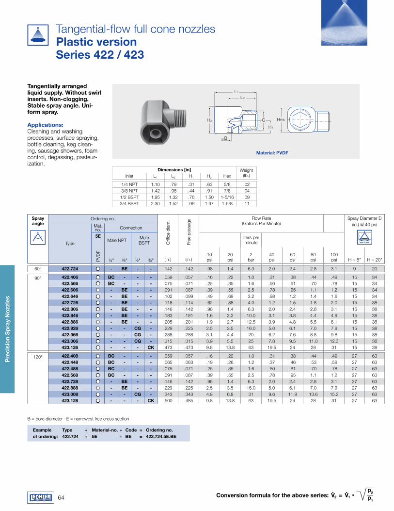
64
Pre
cisi
on
Sp
ray
Noz
zles
Spray angle
Ordering no.
Orifi
ce d
iam
.
Free
pas
sage
Flow Rate(Gallons Per Minute)
Spray Diameter D(in.) @ 40 psi
H
DType
Mat.no. Connection
5EMale NPT Male
BSPTliters per minute
PVD
F
¼" ⅜" ½" ¾" (in.) (in.)10psi
20psi
2bar
40psi
60 psi
80psi
100psi H = 8" H = 20"
60° 422.724 - BE - - .142 .142 .98 1.4 6.3 2.0 2.4 2.8 3.1 9 20
90° 422.406 BC - - - .059 .057 .16 .22 1.0 .31 .38 .44 .49 15 34422.566 BC - - - .075 .071 .25 .35 1.6 .50 .61 .70 .78 15 34422.606 - BE - - .091 .087 .39 .55 2.5 .78 .95 1.1 1.2 15 34422.646 - BE - - .102 .099 .49 .69 3.2 .98 1.2 1.4 1.6 15 34422.726 - BE - - .118 .114 .62 .88 4.0 1.2 1.5 1.8 2.0 15 38422.806 - BE - - .146 .142 .98 1.4 6.3 2.0 2.4 2.8 3.1 15 38422.846 - BE - - .183 .181 1.6 2.2 10.0 3.1 3.8 4.4 4.9 15 38422.886 - BE - - .205 .201 1.9 2.7 12.5 3.9 4.8 5.5 6.1 15 38422.926 - - Cg - .229 .225 2.5 3.5 16.0 5.0 6.1 7.0 7.9 15 38422.966 - - Cg - .288 .288 3.1 4.4 20 6.2 7.6 8.8 9.8 15 38423.006 - - Cg - .315 .315 3.9 5.5 25 7.8 9.5 11.0 12.3 15 38423.126 - - - Ck .473 .473 9.8 13.8 63 19.5 24 28 31 15 38
120° 422.408 BC - - - .059 .057 .16 .22 1.0 .31 .38 .44 .49 27 63422.448 BC - - - .065 .063 .19 .26 1.2 .37 .46 .53 .59 27 63422.488 BC - - - .075 .071 .25 .35 1.6 .50 .61 .70 .78 27 63422.568 BC - - - .091 .087 .39 .55 2.5 .78 .95 1.1 1.2 27 63422.728 - BE - - .146 .142 .98 1.4 6.3 2.0 2.4 2.8 3.1 27 63422.888 - BE - - .229 .225 2.5 3.5 16.0 5.0 6.1 7.0 7.9 27 63423.008 - - Cg - .343 .343 4.8 6.8 31 9.6 11.8 13.6 15.2 27 63423.128 - - - Ck .500 .485 9.8 13.8 63 19.5 24 28 31 27 63
Conversion formula for the above series: v.
2 = v.
1 *p2 p1
Hex
L1
L 2
G
H1
H2
Ø B
material: Pvdf
Tangential-flow full cone nozzles Plastic versionSeries 422 / 423
Tangentially arranged liquid supply. without swirl inserts. Non-clogging. Stable spray angle. Uni-form spray. applications:Cleaning and washing processes, surface spraying, bottle cleaning, keg clean-ing, sausage showers, foam control, degassing, pasteur-ization.
dimensions [in] Weight (lb.)Inlet L1 L2 H1 H2 Hex
1/4 NPT 1.10 .79 .31 .63 5/8 .023/8 NPT 1.42 .98 .44 .91 7/8 .04
1/2 BSPT 1.95 1.32 .76 1.50 1-5/16 .093/4 BSPT 2.30 1.52 .96 1.97 1-5/8 .11
Example Type + material-no. + Code = Ordering no.of ordering: 422.724 + 5E + BE = 422.724.5E.BE
B = bore diameter · E = narrowest free cross section
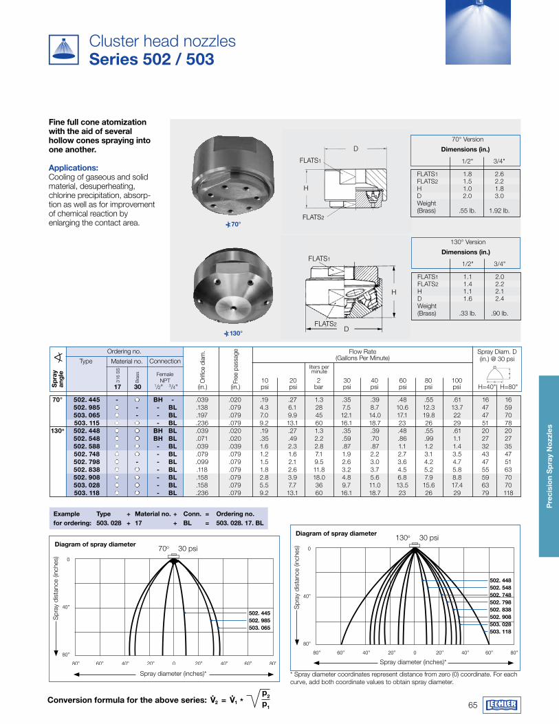
65
Pre
cisi
on
Sp
ray
Noz
zles
Conversion formula for the above series: v.
2 = v.
1 *p2 p1
FLATS1
FLATS2
H
D
FLATS1
H
FLATS2D
<) 70°
<) 130°
70° Version
1/2" 3/4"
FLATS1 1.8 2.6 FLATS2 1.5 2.2 H 1.0 1.8 D 2.0 3.0 Weight (Brass) .55 lb. 1.92 lb.
dimensions (in.)
130° Version
1/2" 3/4"
FLATS1 1.1 2.0 FLATS2 1.4 2.2 H 1.1 2.1 D 1.6 2.4 Weight (Brass) .33 lb. .90 lb.
dimensions (in.)
Cluster head nozzlesSeries 502 / 503
fine full cone atomization with the aid of several hollow cones spraying into one another.
applications:Cooling of gaseous and solid material, desuperheating, chlorine precipitation, absorp-tion as well as for improvement of chemical reaction byenlarging the contact area.
Spray diameter (inches)*
Spray diameter (inches)*
Ordering no. Flow Rate(Gallons Per Minute)Material no.
316
SS
Bra
ss
Connection
FemaleNPT
Example Type + material no. + Conn. = Ordering no.for ordering: 503. 028 + 17 + BL = 503. 028. 17. BL
diagram of spray diameter
Spr
ay d
ista
nce
(inch
es)
502. 445502. 985503. 065
70o 30 psi
diagram of spray diameter
Spr
ay d
ista
nce
(inch
es)
502. 448502. 548502. 748502. 798502. 838502. 908503. 028503. 118
130o 30 psi
Orif
ice
diam
.
Free
pas
sage Spray Diam. D
(in.) @ 30 psi
H
D
Type
70° 502. 445 - Bh - .039 .020 .19 .27 1.3 .35 .39 .48 .55 .61 16 16 502. 985 - - BL .138 .079 4.3 6.1 28 7.5 8.7 10.6 12.3 13.7 47 59 503. 065 - - BL .197 .079 7.0 9.9 45 12.1 14.0 17.1 19.8 22 47 70 503. 115 - BL .236 .079 9.2 13.1 60 16.1 18.7 23 26 29 51 78 130o 502. 448 Bh BL .039 .020 .19 .27 1.3 .35 .39 .48 .55 .61 20 20 502. 548 Bh BL .071 .020 .35 .49 2.2 .59 .70 .86 .99 1.1 27 27 502. 588 - BL .039 .039 1.6 2.3 2.8 .87 .87 1.1 1.2 1.4 32 35 502. 748 - BL .079 .079 1.2 1.6 7.1 1.9 2.2 2.7 3.1 3.5 43 47 502. 798 - - BL .099 .079 1.5 2.1 9.5 2.6 3.0 3.6 4.2 4.7 47 51 502. 838 - BL .118 .079 1.8 2.6 11.8 3.2 3.7 4.5 5.2 5.8 55 63 502. 908 - BL .158 .079 2.8 3.9 18.0 4.8 5.6 6.8 7.9 8.8 59 70 503. 028 - BL .158 .079 5.5 7.7 36 9.7 11.0 13.5 15.6 17.4 63 70 503. 118 - BL .236 .079 9.2 13.1 60 16.1 18.7 23 26 29 79 118
liters per minute
Sp
ray
ang
le
10 20 2 30 40 60 80 100 17 30 1/2" 3/4" (in.) (in.) psi psi bar psi psi psi psi psi H=40" H=80"
* Spray diameter coordinates represent distance from zero (0) coordinate. For each curve, add both coordinate values to obtain spray diameter.
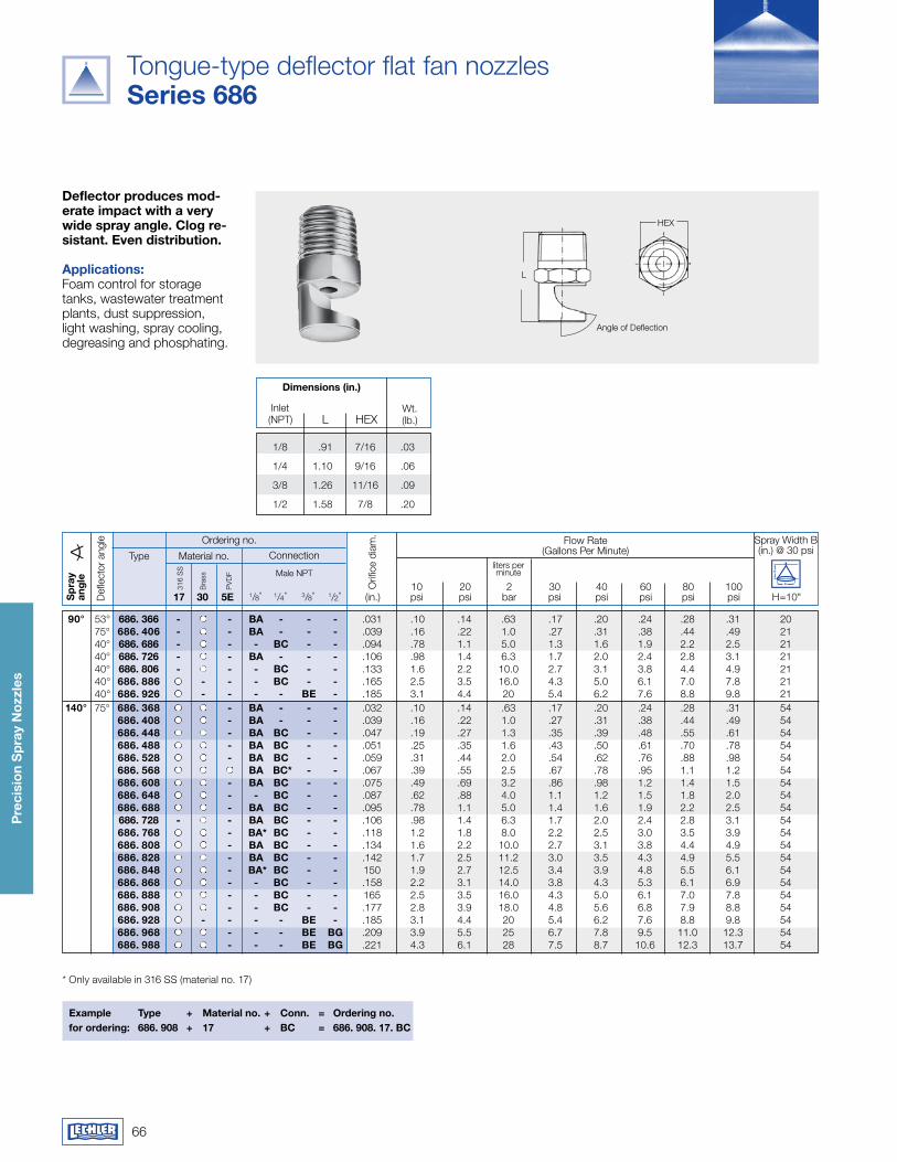
66
Pre
cisi
on
Sp
ray
Noz
zles
Tongue-type deflector flat fan nozzles Series 686
deflector produces mod-erate impact with a very wide spray angle. Clog re-sistant. Even distribution. applications:Foam control for storage tanks, wastewater treatment plants, dust suppression, light washing, spray cooling, degreasing and phosphating.
Example Type + material no. + Conn. = Ordering no.for ordering: 686. 908 + 17 + BC = 686. 908. 17. BC
Spray Width B (in.) @ 30 psi
Ordering no. Flow Rate(Gallons Per Minute)Material no.
316
SS liters per
minute
Connection
Orif
ice
diam
.
Bra
ss
PVD
F Male NPT
Type
* Only available in 316 SS (material no. 17)
90° 53° 686. 366 - - Ba - - - .031 .10 .14 .63 .17 .20 .24 .28 .31 20 75° 686. 406 - - Ba - - - .039 .16 .22 1.0 .27 .31 .38 .44 .49 21 40° 686. 686 - - - BC - - .094 .78 1.1 5.0 1.3 1.6 1.9 2.2 2.5 21 40° 686. 726 - - Ba - - - .106 .98 1.4 6.3 1.7 2.0 2.4 2.8 3.1 21 40° 686. 806 - - - BC - - .133 1.6 2.2 10.0 2.7 3.1 3.8 4.4 4.9 21 40° 686. 886 - - - BC - - .165 2.5 3.5 16.0 4.3 5.0 6.1 7.0 7.8 21 40° 686. 926 - - - - BE - .185 3.1 4.4 20 5.4 6.2 7.6 8.8 9.8 21 140° 75° 686. 368 - Ba - - - .032 .10 .14 .63 .17 .20 .24 .28 .31 54 686. 408 - Ba - - - .039 .16 .22 1.0 .27 .31 .38 .44 .49 54 686. 448 - Ba BC - - .047 .19 .27 1.3 .35 .39 .48 .55 .61 54 686. 488 - Ba BC - - .051 .25 .35 1.6 .43 .50 .61 .70 .78 54 686. 528 - Ba BC - - .059 .31 .44 2.0 .54 .62 .76 .88 .98 54 686. 568 Ba BC* - - .067 .39 .55 2.5 .67 .78 .95 1.1 1.2 54 686. 608 - Ba BC - - .075 .49 .69 3.2 .86 .98 1.2 1.4 1.5 54 686. 648 - - BC - - .087 .62 .88 4.0 1.1 1.2 1.5 1.8 2.0 54 686. 688 - Ba BC - - .095 .78 1.1 5.0 1.4 1.6 1.9 2.2 2.5 54 686. 728 - - Ba BC - - .106 .98 1.4 6.3 1.7 2.0 2.4 2.8 3.1 54 686. 768 - Ba* BC - - .118 1.2 1.8 8.0 2.2 2.5 3.0 3.5 3.9 54 686. 808 - Ba BC - - .134 1.6 2.2 10.0 2.7 3.1 3.8 4.4 4.9 54 686. 828 - Ba BC - - .142 1.7 2.5 11.2 3.0 3.5 4.3 4.9 5.5 54 686. 848 - Ba* BC - - 150 1.9 2.7 12.5 3.4 3.9 4.8 5.5 6.1 54 686. 868 - - BC - - .158 2.2 3.1 14.0 3.8 4.3 5.3 6.1 6.9 54 686. 888 - - BC - - 165 2.5 3.5 16.0 4.3 5.0 6.1 7.0 7.8 54 686. 908 - - BC - - .177 2.8 3.9 18.0 4.8 5.6 6.8 7.9 8.8 54 686. 928 - - - - BE - .185 3.1 4.4 20 5.4 6.2 7.6 8.8 9.8 54 686. 968 - - - BE Bg .209 3.9 5.5 25 6.7 7.8 9.5 11.0 12.3 54 686. 988 - - - BE Bg .221 4.3 6.1 28 7.5 8.7 10.6 12.3 13.7 54
Sp
ray
ang
le
Def
lect
or a
ngle
10 20 2 30 40 60 80 100 17 30 5E 1/8" 1/4" 3/8" 1/2" (in.) psi psi bar psi psi psi psi psi H=10"
dimensions (in.)
L HEX Inlet(NPT)
Wt.(lb.)
1/8 .91 7/16 .03
1/4 1.10 9/16 .06
3/8 1.26 11/16 .09
1/2 1.58 7/8 .20
Angle of Deflection
H
D
L
HEX
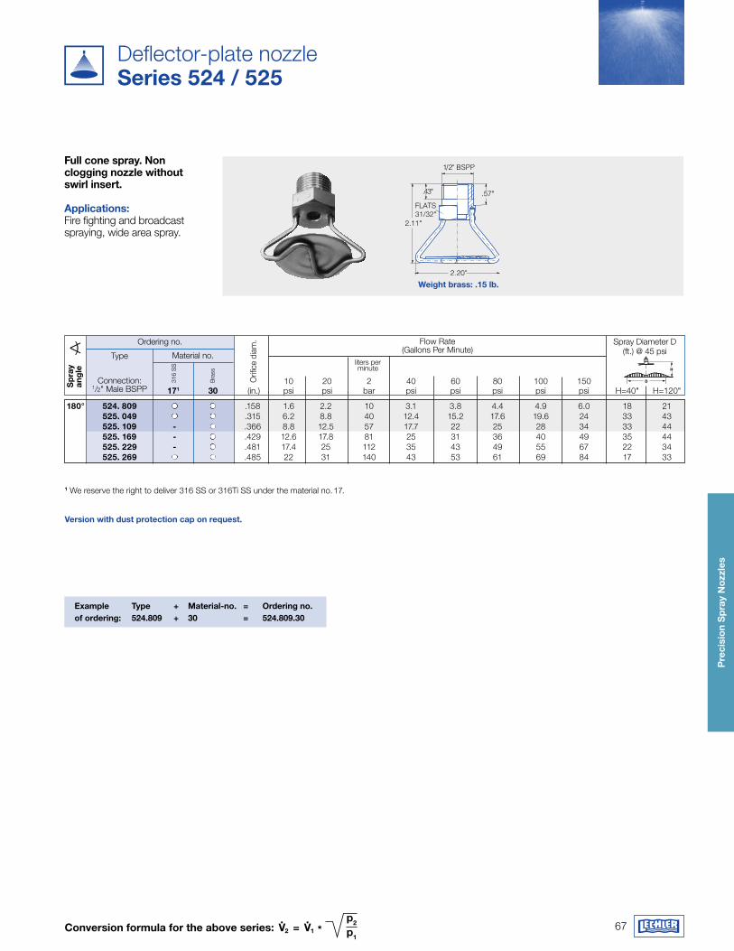
67
Pre
cisi
on
Sp
ray
Noz
zles
Conversion formula for the above series: v.
2 = v.
1 *p2 p1
weight brass: .15 lb.
1/2" BSPP
2.20"
FLATS31/32"
2.11"
.43" .57"
Deflector-plate nozzleSeries 524 / 525
1 We reserve the right to deliver 316 SS or 316Ti SS under the material no. 17. version with dust protection cap on request.
full cone spray. Non clogging nozzle without swirl insert.
applications: Fire fighting and broadcast spraying, wide area spray.
Example Type + material-no. = Ordering no.of ordering: 524.809 + 30 = 524.809.30
Ordering no. Flow Rate(Gallons Per Minute)
Material no.
316
SS liters per
minute
10 20 2 40 60 80 100 150 171 30 (in.) psi psi bar psi psi psi psi psi H=40" H=120"
Spray Diameter D (ft.) @ 45 psi
Bra
ss
Type
Orif
ice
diam
.
D
�H
180° 524. 809 .158 1.6 2.2 10 3.1 3.8 4.4 4.9 6.0 18 21 525. 049 .315 6.2 8.8 40 12.4 15.2 17.6 19.6 24 33 43 525. 109 - .366 8.8 12.5 57 17.7 22 25 28 34 33 44 525. 169 - .429 12.6 17.8 81 25 31 36 40 49 35 44 525. 229 - .481 17.4 25 112 35 43 49 55 67 22 34 525. 269 .485 22 31 140 43 53 61 69 84 17 33
Sp
ray
ang
le
Connection:1/2" Male BSPP
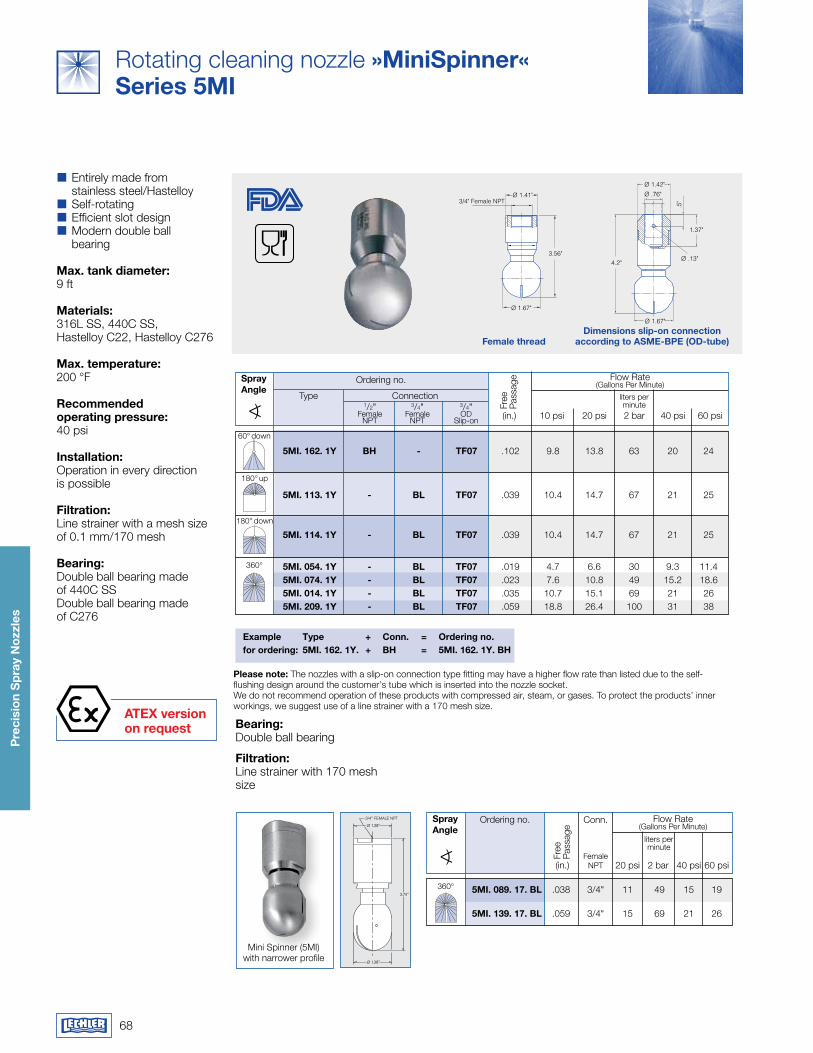
68
Pre
cisi
on
Sp
ray
Noz
zles
aTEx version on request
Ø 1.41"3/4" Female NPT
3.56"
Ø 1.67"
Ø 1.42"
Ø .76"
.5"
1.37"
Ø .13"4.2"
Ø 1.67"
female threaddimensions slip-on connection
according to aSmE-BPE (Od-tube)
Mini Spinner (5MI) with narrower profile
Please note: The nozzles with a slip-on connection type fitting may have a higher flow rate than listed due to the self-flushing design around the customer’s tube which is inserted into the nozzle socket. We do not recommend operation of these products with compressed air, steam, or gases. To protect the products’ inner workings, we suggest use of a line strainer with a 170 mesh size.
Flow Rate(Gallons Per Minute)
Sprayangle
Conn.Ordering no.
Female NPT
liters perminute
3/8" FEMALE NPT 3/4" FEMALE NPT
Ø .85" Ø 1.38"
2.13"
3.74"
Ø .99"
Ø 1.38"
Flow Rate(Gallons Per Minute)Ordering no.Spray
angleliters perminute
(in.) 10 psi 20 psi 2 bar 40 psi 60 psi1/2"
FemaleNPT
Type3/4"
FemaleNPT
3/4" OD
Slip-on
Connection
Example Type + Conn. = Ordering no.for ordering: 5mI. 162. 1y. + Bh = 5mI. 162. 1y. Bh
Free
Pa
ssag
e
(in.) 20 psi 2 bar 40 psi 60 psi
Free
Pa
ssag
e
360° 5mI. 089. 17. BL .038 3/4" 11 49 15 19 5mI. 139. 17. BL .059 3/4" 15 69 21 26
Bearing:Double ball bearing
filtration:Line strainer with 170 mesh size
60° down
360°
180° up
5mI. 162. 1y Bh - Tf07 .102 9.8 13.8 63 20 24 5mI. 113. 1y - BL Tf07 .039 10.4 14.7 67 21 25
5mI. 114. 1y - BL Tf07 .039 10.4 14.7 67 21 25
5mI. 054. 1y - BL Tf07 .019 4.7 6.6 30 9.3 11.4 5mI. 074. 1y - BL Tf07 .023 7.6 10.8 49 15.2 18.6 5mI. 014. 1y - BL Tf07 .035 10.7 15.1 69 21 26 5mI. 209. 1y - BL Tf07 .059 18.8 26.4 100 31 38
180° down
Rotating cleaning nozzle »miniSpinner«Series 5mI
�� Entirely made from stainless steel/Hastelloy�� Self-rotating�� Efficient slot design�� Modern double ball bearing
max. tank diameter:9 ft
materials:316L SS, 440C SS, Hastelloy C22, Hastelloy C276
max. temperature:200 °F
recommended operating pressure:40 psi
Installation:Operation in every directionis possible
filtration:Line strainer with a mesh sizeof 0.1 mm/170 mesh
Bearing:Double ball bearing madeof 440C SS Double ball bearing made of C276
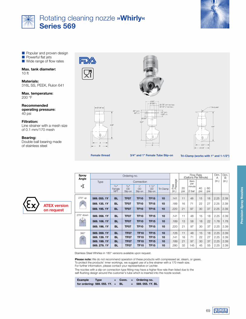
69
Pre
cisi
on
Sp
ray
Noz
zles
aTEx version on request
A
5.21"
Ø .125"
.50" (3/4")
.63" (1")
Ø 1.50"2.52"
1.0" (3/4")
1.125" (1")
Ø .75" (3/4" Inlet Tube)
Ø 1.0" (1" Inlet Tube )
B
4.84"
1" TRI-CLAMP
2.25"
Ø 2.39"
Ø 1.38"
A
B
4.06"
Flow Rate(Gallons Per Minute)
liters per
minute
Connection
Example Type + Conn. = Ordering no.for ordering: 569. 055. 1y. + BL = 569. 055. 1y. BL
3/4" Female
NPT
Ordering no.
20 40 60 (in.) psi 2 bar psi psi
1" OD
Slip-on
Tri-Clamp
3/4" OD
Slip-on
Sprayangle
Type
Dim. A
(in.)
Please note: We do not recommend operation of these products with compressed air, steam, or gases. To protect the products’ inner workings, we suggest use of a line strainer with a 170 mesh size. For further information, please contact your representative or Lechler.The nozzles with a slip-on connection type fitting may have a higher flow rate than listed due to the self-flushing design around the customer’s tube which is inserted into the nozzle socket.
Dim. B
(in.)
1 1/2" OD
Slip-on
Stainless Steel Whirlies in 180° versions available upon request.
Free
Pa
ssag
e
270° down
270° up
360°
569. 056. 1y BL Tf07 Tf10 Tf15 10 .141 11 48 15 18 2.25 2.39
569. 106. 1y BL Tf07 Tf10 Tf15 10 .189 13 58 18 22 1.78 1.78
569. 196. 1y BL Tf07 Tf10 Tf15 10 .220 21 97 30 37 2.25 2.39
569. 055. 1y BL Tf07 Tf10 Tf15 10 .141 11 48 15 18 2.25 2.39
569. 135. 1y BL Tf07 Tf10 Tf15 10 .189 16 71 22 27 2.25 2.39
569. 195. 1y BL Tf07 Tf10 Tf15 10 .220 21 97 30 37 2.25 2.39
569. 059. 1y BL Tf07 Tf10 Tf15 10 .126 11 48 15 18 2.25 2.39 569. 139. 1y BL Tf07 Tf10 Tf15 10 .141 16 71 22 27 2.25 2.39 569. 199. 1y BL Tf07 Tf10 Tf15 10 .189 21 97 30 37 2.25 2.39 569. 279. 1y BL Tf07 Tf10 Tf15 10 .280 32 145 45 55 2.25 2.39
female thread Tri-Clamp (works with 1" and 1-1/2")3/4" and 1" female Tube Slip-on
Rotating cleaning nozzle »whirly«Series 569
�� Popular and proven design�� Powerful flat jets�� Wide range of flow rates
max. tank diameter:10 ft
materials:316L SS, PEEK, Rulon 641
max. temperature:200 °F
recommended operating pressure:40 psi
filtration:Line strainer with a mesh sizeof 0.1 mm/170 mesh
Bearing:Double ball bearing madeof stainless steel
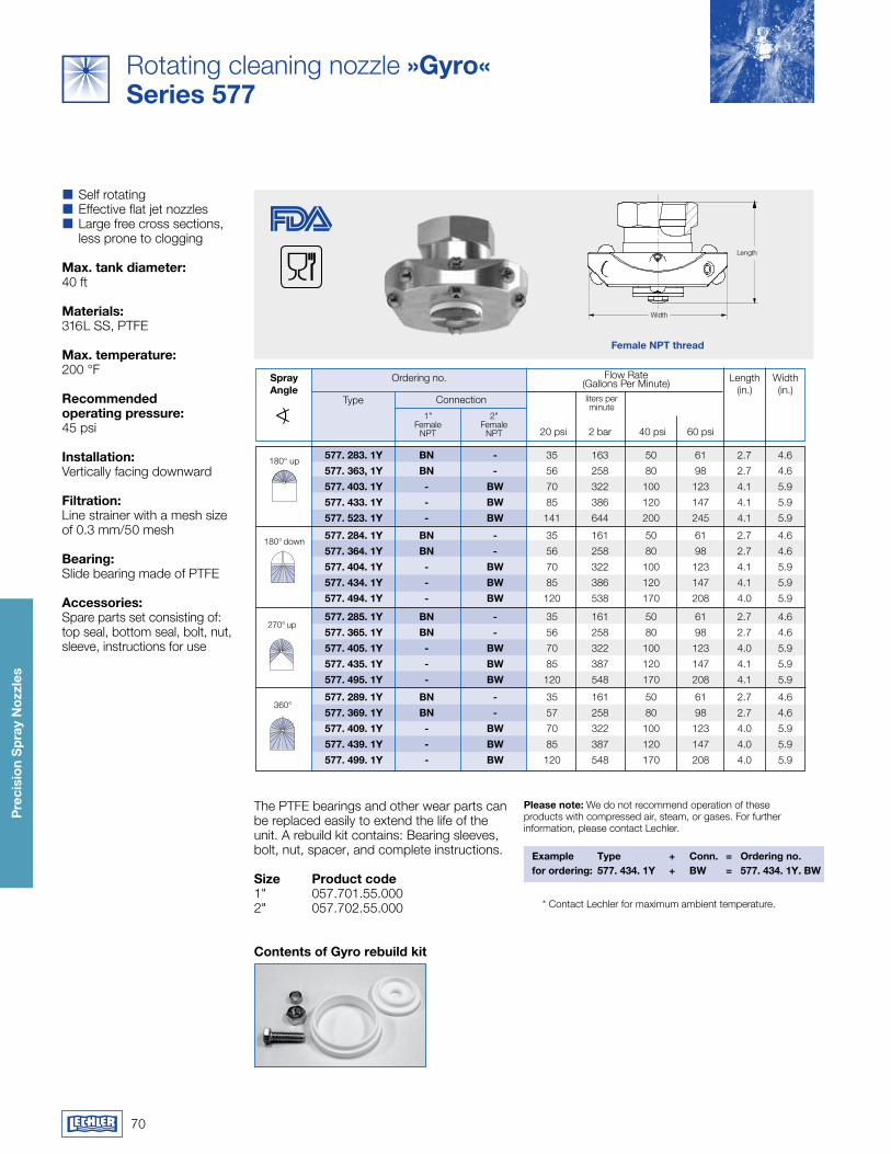
70
Pre
cisi
on
Sp
ray
Noz
zles
Length
Width
female NPT thread
Rotating cleaning nozzle »gyro«Series 577
�� Self rotating�� Effective flat jet nozzles�� Large free cross sections, less prone to clogging
max. tank diameter:40 ft
materials:316L SS, PTFE
max. temperature:200 °F
recommended operating pressure:45 psi
Installation:Vertically facing downward
filtration:Line strainer with a mesh sizeof 0.3 mm/50 mesh
Bearing:Slide bearing made of PTFE
accessories:Spare parts set consisting of:top seal, bottom seal, bolt, nut, sleeve, instructions for use
Flow Rate(Gallons Per Minute)
Connection
Ordering no.Sprayangle
liters per minute
Length(in.)
Width(in.)
20 psi 2 bar 40 psi 60 psi
1"Female
NPT
2"Female
NPT
Type
Please note: We do not recommend operation of these products with compressed air, steam, or gases. For further information, please contact Lechler.
Contents of gyro rebuild kit
The PTFE bearings and other wear parts can be replaced easily to extend the life of the unit. A rebuild kit contains: Bearing sleeves, bolt, nut, spacer, and complete instructions.
Size Product code1" 057.701.55.0002" 057.702.55.000
Example Type + Conn. = Ordering no.for ordering: 577. 434. 1y + Bw = 577. 434. 1y. Bw
* Contact Lechler for maximum ambient temperature.
180° down
270° up
360°
180° up 577. 283. 1y BN - 35 163 50 61 2.7 4.6
577. 363, 1y BN - 56 258 80 98 2.7 4.6
577. 403. 1y - Bw 70 322 100 123 4.1 5.9
577. 433. 1y - Bw 85 386 120 147 4.1 5.9
577. 523. 1y - Bw 141 644 200 245 4.1 5.9
577. 284. 1y BN - 35 161 50 61 2.7 4.6
577. 364. 1y BN - 56 258 80 98 2.7 4.6
577. 404. 1y - Bw 70 322 100 123 4.1 5.9
577. 434. 1y - Bw 85 386 120 147 4.1 5.9
577. 494. 1y - Bw 120 538 170 208 4.0 5.9
577. 285. 1y BN - 35 161 50 61 2.7 4.6
577. 365. 1y BN - 56 258 80 98 2.7 4.6
577. 405. 1y - Bw 70 322 100 123 4.0 5.9
577. 435. 1y - Bw 85 387 120 147 4.1 5.9
577. 495. 1y - Bw 120 548 170 208 4.1 5.9
577. 289. 1y BN - 35 161 50 61 2.7 4.6
577. 369. 1y BN - 57 258 80 98 2.7 4.6
577. 409. 1y - Bw 70 322 100 123 4.0 5.9
577. 439. 1y - Bw 85 387 120 147 4.0 5.9
577. 499. 1y - Bw 120 548 170 208 4.0 5.9
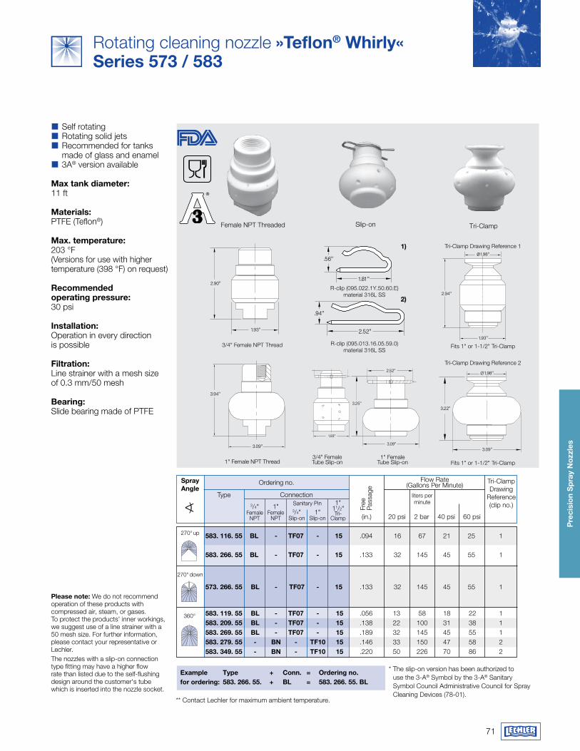
71
Pre
cisi
on
Sp
ray
Noz
zles
Female NPT Threaded Slip-on Tri-Clamp
Example Type + Conn. = Ordering no.for ordering: 583. 266. 55. + BL = 583. 266. 55. BL
** Contact Lechler for maximum ambient temperature.
* The slip-on version has been authorized to use the 3-A® Symbol by the 3-A® Sanitary Symbol Council Administrative Council for Spray Cleaning Devices (78-01).
Please note: We do not recommend operation of these products with compressed air, steam, or gases. To protect the products’ inner workings, we suggest use of a line strainer with a 50 mesh size. For further information, please contact your representative or Lechler.The nozzles with a slip-on connection type fitting may have a higher flow rate than listed due to the self-flushing design around the customer's tube which is inserted into the nozzle socket.
1.93"
2.90"
Fits 1" or 1-1/2" Tri-Clamp
3.09"
3.22"
Ø1.98"
3.09"
3.25"
2.52"
1.93"
3.25"
1.81"Tri-Clamp Drawing Reference 2
3/4" Female Tube Slip-on
3/4" Female NPT Thread
3.09"
3.94"
1.93"
2.94"
Ø1.98"
Fits 1" or 1-1/2" Tri-Clamp1" Female
Tube Slip-on1" Female NPT Thread
Flow Rate(Gallons Per Minute)
3/4" Female
NPT
Ordering no.Sprayangle
liters per minute
(in.) 20 psi 2 bar 40 psi 60 psi
1" Female
NPT
ConnectionSanitary Pin
Tri-Clamp Drawing
Reference(clip no.)
3/4" Slip-on
1" Slip-on
Type1"
11/2" Tri-
Clamp
Tri-Clamp Drawing Reference 1
.56"
1.81"
.94"
2.52"
1)
2)
Free
Pa
ssag
e
R-clip (095.022.1Y.50.60.E)material 316L SS
R-clip (095.013.16.05.59.0)material 316L SS
360°
270° up
270° down
583. 116. 55 BL - Tf07 - 15 .094 16 67 21 25 1 583. 266. 55 BL - Tf07 - 15 .133 32 145 45 55 1
573. 266. 55 BL - Tf07 - 15 .133 32 145 45 55 1
583. 119. 55 BL - Tf07 - 15 .056 13 58 18 22 1 583. 209. 55 BL - Tf07 - 15 .138 22 100 31 38 1 583. 269. 55 BL - Tf07 - 15 .189 32 145 45 55 1 583. 279. 55 - BN - Tf10 15 .146 33 150 47 58 2 583. 349. 55 - BN - Tf10 15 .220 50 226 70 86 2
* Contact Lechler for maximum ambient temperature.
Rotating cleaning nozzle »Teflon® whirly«Series 573 / 583
�� Self rotating�� Rotating solid jets�� Recommended for tanks made of glass and enamel�� 3A® version available
max tank diameter:11 ft
materials:PTFE (Teflon®)
max. temperature:203 °F(Versions for use with highertemperature (398 °F) on request)
recommended operating pressure:30 psi
Installation:Operation in every directionis possible
filtration:Line strainer with a mesh sizeof 0.3 mm/50 mesh
Bearing:Slide bearing made of PTFE
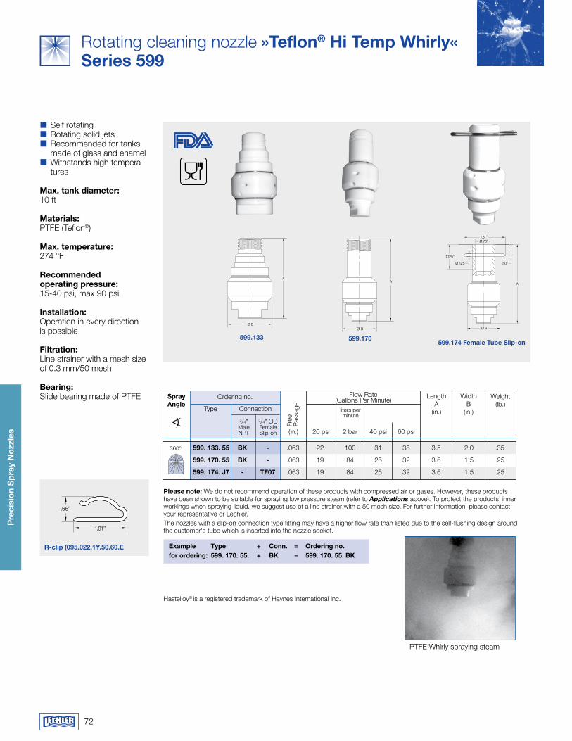
72
Pre
cisi
on
Sp
ray
Noz
zles
Rotating cleaning nozzle »Teflon® hi Temp whirly«Series 599
.66"
1.81"
r-clip (095.022.1y.50.60.E
599.133 599.170599.174 female Tube Slip-on
�� Self rotating�� Rotating solid jets�� Recommended for tanks made of glass and enamel�� Withstands high tempera-tures
max. tank diameter:10 ft
materials:PTFE (Teflon®)
max. temperature:274 °F
recommended operating pressure:15-40 psi, max 90 psi
Installation:Operation in every directionis possible
filtration:Line strainer with a mesh sizeof 0.3 mm/50 mesh
Bearing:Slide bearing made of PTFE
Ø B
A
Ø B
A
1.125"
A
Ø .76"
Ø B
Ø .125" .50"
1.81"
Example Type + Conn. = Ordering no.for ordering: 599. 170. 55. + Bk = 599. 170. 55. Bk
Hastelloy® is a registered trademark of Haynes International Inc.
Flow Rate(Gallons Per Minute)
3/4"Male NPT
Ordering no.Sprayangle
liters per minute
20 psi 2 bar 40 psi 60 psi
Connection
LengthA
(in.)
WidthB
(in.)
Weight(lb.)
3/4" ODFemale Slip-on
Please note: We do not recommend operation of these products with compressed air or gases. However, these products have been shown to be suitable for spraying low pressure steam (refer to Applications above). To protect the products’ inner workings when spraying liquid, we suggest use of a line strainer with a 50 mesh size. For further information, please contact your representative or Lechler.The nozzles with a slip-on connection type fitting may have a higher flow rate than listed due to the self-flushing design around the customer's tube which is inserted into the nozzle socket.
Type
PTFE Whirly spraying steam
Free
Pa
ssag
e
(in.)
360° 599. 133. 55 Bk - .063 22 100 31 38 3.5 2.0 .35
599. 170. 55 Bk - .063 19 84 26 32 3.6 1.5 .25
599. 174. J7 - TF07 .063 19 84 26 32 3.6 1.5 .25
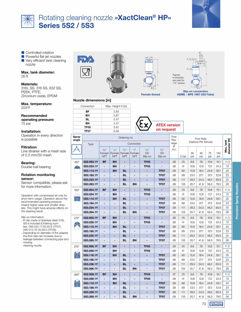
73
Pre
cisi
on
Sp
ray
Noz
zles
aTEx version on request
H
2.68"Ø 3"
Ø 1.73"
H
Ø .5
" (.2
5")
Ø .1
3" (Ø
.09"
)
2.68"Ø 3"
Ø .76" (Ø .5")
Ø 1.73"
1.18
"(.6
3")
Figures in brackets are valid for 1/2" version
female threadSlip-on connection
aSmE - BPE 1997 (Od-Tube)
Rotating cleaning nozzle »xactClean® hP«Series 5S2 / 5S3
�� Controlled rotation�� Powerful flat jet nozzles�� Very efficient tank cleaning nozzle
max. tank diameter:26 ft
materials:316L SS, 316 SS, 632 SS, PEEK, PTFE, Zirconium oxide, EPDM
max. temperature:203°F
recommended operating pressure:75 psi
Installation:Operation in every directionis possible
filtration:Line strainer with a mesh size of 0.3 mm/50 mesh
Bearing:Double ball bearing
rotation monitoring sensor:Sensor compatible, please ask for more information.
Operation with compressed air only for short-term usage. Operation above the recommended operating pressure means higher wear and smaller drop-lets. This might have adverse effects on the cleaning result.
Slip-on information: - R-clip made of stainless steel 316L
SS is included (Ordering num-ber: 095.022.1Y.50.60.E (TF07), 095.013.1E.05.59.0 (TF05)).
- Depending on diameter of the adapter the flow rate can increase due to leakage between connecting pipe and rotating cleaning nozzle.
Connection Max. Height H [in]
Bf 5.83Bh 5.87BL 5.47BN 5.47
Tf05 5.91Tf07 6.46
Nozzle dimensions [in]
Spray angle
Ordering no. FreePas-sage
Ø(in.)
Flow Rate(Gallons Per Minute)
max
. tan
k
diam
eter
[ft]
Type Connection
3/8" Female
NPT
1/2"Female
NPT
3/4"Female
NPT
1" Female
NPT
1/2"OD
Slip-on
3/4"OD
Slip-on 2 bar30psi
40psi
75psi
145psi
180° 5S2.953.1y Bf Bh - - Tf05 - .08 25 6.6 7.8 10.6 15.1 11.5
5S3.053.1y - Bh - - Tf05 - .08 41 10.8 12.8 17.2 24.3 13
5S3.113.1y - Bh BL - - Tf07 .08 60 15.9 18.4 24.8 35.1 20
5S3.183.1y - - BL - - Tf07 .08 89 23.5 27.7 37.3 52.6 23
5S3.233.1y - - BL - - Tf07 .08 111 29.3 34.3 46.2 65.5 25
5S3.263.1y - - BL BN - Tf07 .08 135 35.7 41.8 56.3 79.5 26
180° 5S2.954.1y Bf Bh - - Tf05 - .08 25 6.6 7.8 10.6 15.1 11.5
5S3.054.1y - Bh - - Tf05 - .08 41 10.8 12.8 17.2 24.3 13
5S3.114.1y - Bh BL - - Tf07 .08 60 15.9 18.4 24.8 35.1 20
5S3.184.1y - - BL - - Tf07 .08 89 23.5 27.7 37.3 52.6 23
5S3.234.1y - - BL - - Tf07 .08 111 29.3 34.3 46.2 65.5 25
5S3.264.1y - - BL BN - Tf07 .08 135 35.7 41.8 56.3 79.5 26
270° 5S2.955.1y Bf Bh - - Tf05 - .08 25 6.6 7.8 10.6 15.1 11.5
5S3.055.1y - Bh - - Tf05 - .08 41 10.8 12.8 17.2 24.3 13
5S3.115.1y - Bh BL - - Tf07 .08 60 15.9 18.4 24.8 35.1 20
5S3.185.1y - - BL - - Tf07 .08 89 23.5 27.7 37.3 52.6 23
5S3.235.1y - - BL - - Tf07 .08 111 29.3 34.3 46.2 65.5 25
5S3.265.1y - - BL BN - Tf07 .08 135 35.7 41.8 56.3 79.5 26
270° 5S2.956.1y Bf Bh - - Tf05 - .08 25 6.6 7.8 10.6 15.1 11.5
5S3.056.1y - Bh - - Tf05 - .08 41 10.8 12.8 17.2 24.3 13
5S3.116.1y - Bh BL - - Tf07 .08 60 15.9 18.4 24.8 35.1 20
5S3.186.1y - - BL - - Tf07 .08 89 23.5 27.7 37.3 52.6 23
5S3.236.1y - - BL - - Tf07 .08 111 29.3 34.3 46.2 65.5 25
5S3.266.1y - - BL BN - Tf07 .08 135 35.7 41.8 56.3 79.5 26
360° 5S2.959.1y Bf Bh - - Tf05 - .07 25 6.6 7.8 10.6 15.1 11.5
5S3.059.1y - Bh - - Tf05 - .08 41 10.8 12.8 17.2 24.3 13
5S3.119.1y - Bh BL - - Tf07 .08 60 15.9 18.4 24.8 35.1 20
5S3.189.1y - - BL - - Tf07 .08 89 23.5 27.7 37.3 52.6 23
5S3.239.1y - - BL - - Tf07 .08 111 29.3 34.3 46.2 65.5 25
5S3.269.1y - - BL BN - Tf07 .08 135 35.7 41.8 56.3 79.5 26
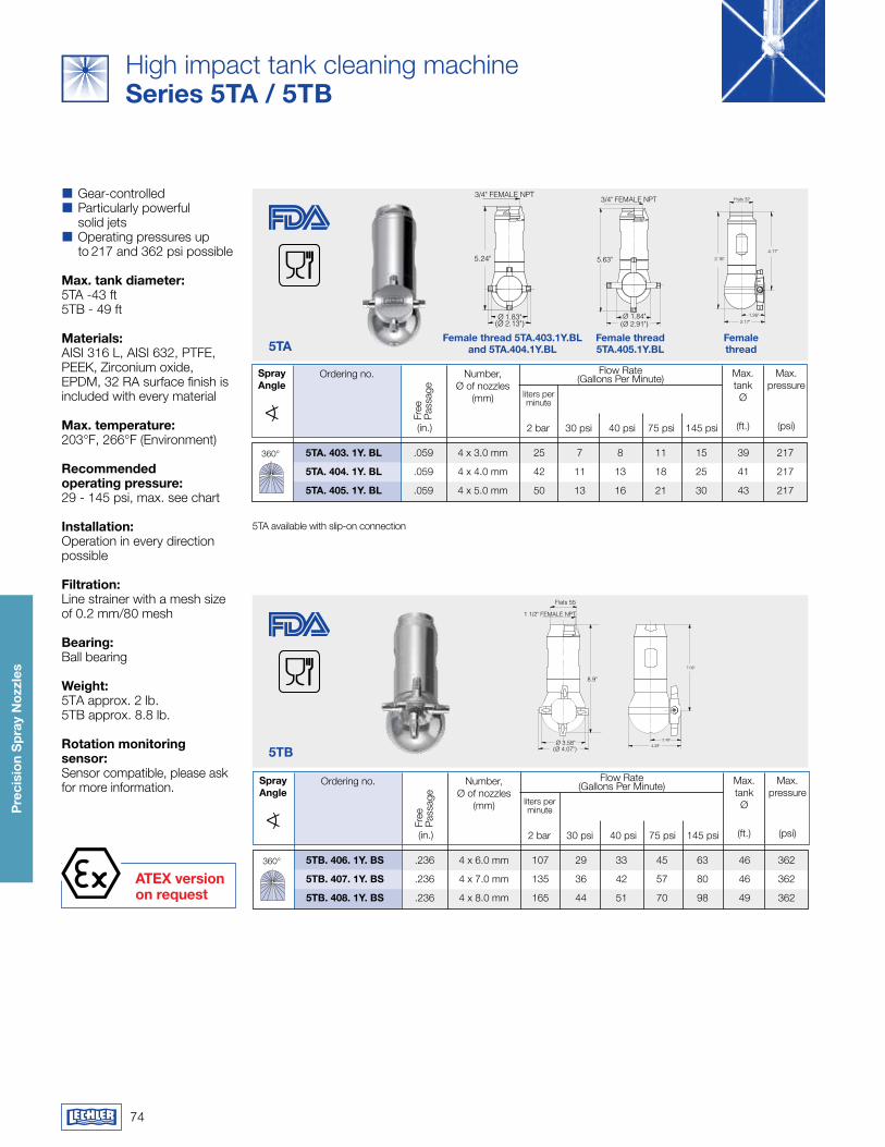
74
Pre
cisi
on
Sp
ray
Noz
zles
aTEx version on request
5Ta
min. Ø 2.48"
3/4" FEMALE NPT
(Ø 2.13")
2.16"5.24"
Flats 32
4.17"
1.26"2.17"
Ø 1.83"
min. Ø 3.27"
3/4" FEMALE NPT Flats 32
5.16"5.63"
4.17"
1.26"2.16"
Ø 1.84"(Ø 2.91")
min. Ø 2.48"
3/4" FEMALE NPT
(Ø 2.13")
2.16"5.24"
Flats 32
4.17"
1.26"2.17"
Ø 1.83"
female thread 5Ta.403.1y.BL and 5Ta.404.1y.BL
female thread
female thread 5Ta.405.1y.BL
5TB
min. Ø 5.12"
Flats 55
1 1/2" FEMALE NPT
8.9"
7.09"
2.48"
4.29"(Ø 4.07")Ø 3.58"
Flow Rate(Gallons Per Minute)Ordering no.Spray
angleliters per minute
2 bar 30 psi 40 psi 75 psi 145 psi
Max. pressure
(psi)Fr
ee
Pass
age
(in.)
Number,Ø of nozzles
(mm)
Max. tankØ
(ft.)
360° 5Ta. 403. 1y. BL .059 4 x 3.0 mm 25 7 8 11 15 39 217
5Ta. 404. 1y. BL .059 4 x 4.0 mm 42 11 13 18 25 41 217
5Ta. 405. 1y. BL .059 4 x 5.0 mm 50 13 16 21 30 43 217
High impact tank cleaning machine Series 5Ta / 5TB
�� Gear-controlled�� Particularly powerful solid jets�� Operating pressures up to 217 and 362 psi possible
max. tank diameter:5TA -43 ft 5TB - 49 ft
materials:AISI 316 L, AISI 632, PTFE, PEEK, Zirconium oxide, EPDM, 32 RA surface finish is included with every material
max. temperature:203°F, 266°F (Environment)
recommended operating pressure:29 - 145 psi, max. see chart
Installation:Operation in every direction possible
filtration:Line strainer with a mesh size of 0.2 mm/80 mesh
Bearing:Ball bearing
weight: 5TA approx. 2 lb.5TB approx. 8.8 lb.
rotation monitoring sensor: Sensor compatible, please ask for more information.
5TA available with slip-on connection
Flow Rate(Gallons Per Minute)Ordering no.Spray
angleliters per minute
2 bar 30 psi 40 psi 75 psi 145 psi
Max. pressure
(psi)
Free
Pa
ssag
e
(in.)
Number,Ø of nozzles
(mm)
Max. tankØ
(ft.)
360° 5TB. 406. 1y. BS .236 4 x 6.0 mm 107 29 33 45 63 46 362
5TB. 407. 1y. BS .236 4 x 7.0 mm 135 36 42 57 80 46 362
5TB. 408. 1y. BS .236 4 x 8.0 mm 165 44 51 70 98 49 362
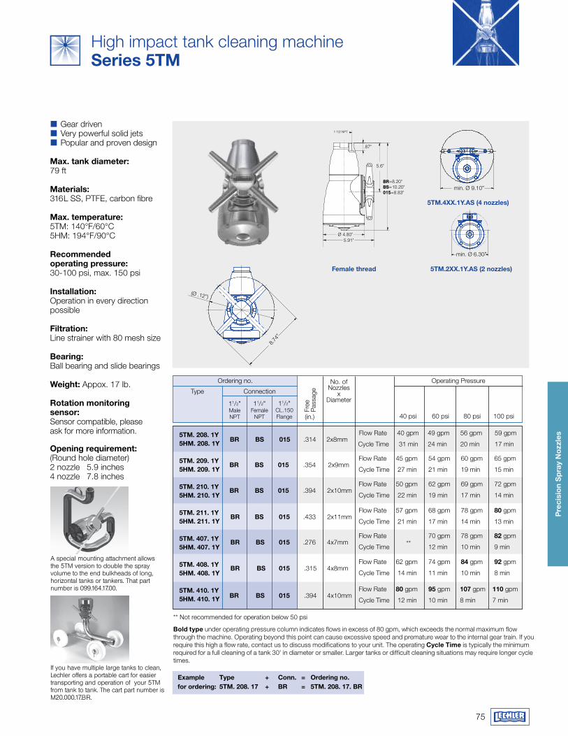
75
Pre
cisi
on
Sp
ray
Noz
zles
8.74"
(Ø 8.78")
1 1/2 NPT
.87"
5.6"
5.91"Ø 4.80"
BR=8.20"BS=10.20"015=8.83"
8.74
”
(Ø .12”)
1 1/2 NPT
.87”
5.67”
10.20”
5.91”
Ø 4.8”
min. Ø 9.10” min. Ø 6.30”
min. Ø 9.10” min. Ø 6.30”
5Tm.2xx.1y.aS (2 nozzles)female thread
5Tm.4xx.1y.aS (4 nozzles)
High impact tank cleaning machine Series 5Tm
�� Gear driven�� Very powerful solid jets�� Popular and proven design
max. tank diameter:79 ft
materials:316L SS, PTFE, carbon fibre
max. temperature:5TM: 140°F/60°C5HM: 194°F/90°C
recommended operating pressure:30-100 psi, max. 150 psi
Installation:Operation in every direction possible
filtration:Line strainer with 80 mesh size
Bearing:Ball bearing and slide bearings
weight: Appox. 17 lb.
rotation monitoring sensor: Sensor compatible, please ask for more information.
Opening requirement: (Round hole diameter)2 nozzle 5.9 inches4 nozzle 7.8 inches
No. of Nozzles
xDiameter
Ordering no.
Connection
Operating Pressure
11/2"MaleNPT
11/2"Female
NPT
11/2"CL.150 Flange
Type
40 psi 60 psi 80 psi 100 psi
(in.)
Free
Pa
ssag
e
Flow Rate 50 gpm 62 gpm 69 gpm 72 gpm
Br BS 015 .394 2x10mm Cycle Time 22 min 19 min 17 min 14 min
Flow Rate 57 gpm 68 gpm 78 gpm 80 gpm
Br BS 015 .433 2x11mm Cycle Time 21 min 17 min 14 min 13 min
Flow Rate 40 gpm 49 gpm 56 gpm 59 gpm
Br BS 015 .314 2x8mm Cycle Time 31 min 24 min 20 min 17 min
Flow Rate 45 gpm 54 gpm 60 gpm 65 gpm
Br BS 015 .354 2x9mm Cycle Time 27 min 21 min 19 min 15 min
Flow Rate
** 70 gpm 78 gpm 82 gpm
Br BS 015 .276 4x7mm Cycle Time 12 min 10 min 9 min
Flow Rate 80 gpm 95 gpm 107 gpm 110 gpm
Br BS 015 .394 4x10mm Cycle Time 12 min 10 min 8 min 7 min
Flow Rate 62 gpm 74 gpm 84 gpm 92 gpm
Br BS 015 .315 4x8mm Cycle Time 14 min 11 min 10 min 8 min
5Tm. 208. 1y 5hm. 208. 1y
5Tm. 209. 1y5hm. 209. 1y
5Tm. 210. 1y5hm. 210. 1y
5Tm. 211. 1y5hm. 211. 1y
5Tm. 407. 1y5hm. 407. 1y
5Tm. 408. 1y5hm. 408. 1y
5Tm. 410. 1y5hm. 410. 1y
Bold type under operating pressure column indicates flows in excess of 80 gpm, which exceeds the normal maximum flow through the machine. Operating beyond this point can cause excessive speed and premature wear to the internal gear train. If you require this high a flow rate, contact us to discuss modifications to your unit. The operating Cycle Time is typically the minimum required for a full cleaning of a tank 30' in diameter or smaller. Larger tanks or difficult cleaning situations may require longer cycle times.
** Not recommended for operation below 50 psi
Example Type + Conn. = Ordering no.for ordering: 5Tm. 208. 17 + Br = 5Tm. 208. 17. Br
If you have multiple large tanks to clean, Lechler offers a portable cart for easier transporting and operation of your 5TM from tank to tank. The cart part number is M20.000.17.BR.
A special mounting attachment allows the 5TM version to double the spray volume to the end bulkheads of long, horizontal tanks or tankers. That part number is 099.164.17.00.
76
QUaLITy wITh a SySTEm
Lechler products are used in a wide variety of sectors and applications. which is why the products’ requirements are often very specific to certain applications. We define the term "quality" as the extent to which our products fulfill our customer’s individual requirements.
In order to do this we have been certified to internationally renowned certificates.
certifications and Quality
� ISO 9001-2008 Certification � DIN EN 10204 Inspection Certificate � Classification according to Pressure Equipment Directive 2014/68/EU
� Declaration of Incorporation of partly completed machinery according to 2006/42/EC
� Declaration of Conformity of machinery according to 2006/42/EC
� ASME qualified welding procedure specifications � Welding procedure specification DIN EN ISO 15609
Code Compliance
� ASME B31.1 Power Piping Code � Metallic industrial piping: DIN EN 13480 � Unfired pressure vessels: DIN EN 13445 � ASME B31.3 Process Piping Code � Welder Performance Qualification Records per ASME BPVC Section IX
� Qualification test of welders: DIN EN 287
Testing
� ANSI and ASTM testing � Non-destructive testing – Penetrant testing: DIN EN ISO 3452
� Hardness � Hydrostatic pressure test: Pressure Equipment Directive 2014/68/EU, DIN EN 13480-5 and DIN EN 13445-5
� Spray and flow testing � Phase Doppler Anemometry (PDA) measurement system � Magnetic particle inspection : DIN EN ISO 17638 � Positive Material Identification
Talk to us
Your requirements are the first step towards a solution. We are more than happy to help you solve your individual tasks. Tell us your objectives and we will take care of the solution. If the solution is not yet available, we will tailor- make one for you. That is our promise.
... !

77
fOr yOUr NOTES

fOr yOUr NOTES
78

79

LechLer worLd-wide
ed
itio
n 07
/18
· S
ubje
ct to
tech
nica
l mod
ifica
tion.
Lechler, inc · Precision Nozzles · Nozzle Systems445 Kautz road, St. charles, iL 60174 • Phone (800) 777-2926 • Fax (630) 377-6657 • [email protected] • www.LechlerUSA.com
ASeAN: Lechler Spray Technology Sdn. Bhd. · No. 23, Jalan Teknologi 3/3A · Taman Sains Selangor 1 · Kota Damansara, PJU 5 · 47810 Petaling Jaya · Malaysia · [email protected]: Lechler S.A./N.V. · Avenue Mercator, 6 · 1300 Wavre · Phone: +32 10 225022 · Fax: +32 10 243901 · [email protected]: Lechler Intl. Trad. Co. Ltd. · Beijing · Rm. 418 Landmark Tower · No. 8 Dong San Huan Bei Lu · Phone: +86 10 84537968, Fax: +86 10 84537458 · [email protected]: Lechler Oy · Jäspilänkatu 18 · 04250 Kerava · Phone: +358 207 856880 · Fax: +358 207 856881 · [email protected]: Lechler France, S.A. · Bât. CAP2 · 66-72, Rue Marceau · 93558 Montreuil · Phone: +33 1 49882600 · Fax: +33 1 49882609 · [email protected]: Lechler GmbH · PO Box 13 23 · 72544 Metzingen · Phone: +49 7123 962-0 · Fax: (49) 7123 962-444 · [email protected] Britain: Lechler Ltd. · 1 Fell Street, Newhall · Sheffield, S9 2TP · Phone: +44 114 2492020 · Fax: +44 114 2493600 · [email protected]: Lechler (India) Pvt. Ltd. · Plot B-2 · Main Road · Wagle Industrial Estate · Thane (W) - 400604 · Phone: +91 22 40634444 · Fax: +91 22 40634498 · [email protected]: Lechler Spray Technology S.r.l. · Via Don Dossetti, 2 · 20080 Carpiano (Mi) · Phone: +39 02 98859027 · Fax: +39 02 9815647 · [email protected]: Lechler S.A. · Avda. Pirineos 7 · Oficina B7, Edificio Inbisa I · 28700 San Sebastián de los Reyes, Madrid · Phone: +34 91 6586346 · Fax: +34 91 6586347 · [email protected]: Lechler AB · Kungsängsvägen 31 B · 753 23 Uppsala · Phone: +46 18 167030 · Fax: +46 18 167031 · [email protected]