Embed Size (px)
Citation preview
SOLID CONE SPRAY NOZZLESTECHNICAL DATA
The Viking Corporation, 210 N Industrial Park Drive, Hastings MI 49058Telephone: 269-945-9501 Technical Services: 877-384-5464 Fax: 269-818-1680 Email: [email protected]
Form No. F_030789 Rev 14.1
Page 1 of 13
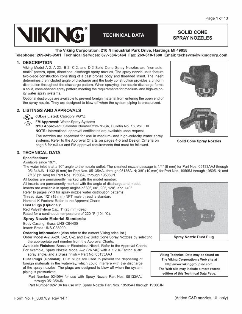
1. DESCRIPTIONViking Model A-2, A-2X, B-2, C-2, and D-2 Solid Cone Spray Nozzles are “non-auto- matic” pattern, open, directional discharge spray nozzles. The spray nozzle units feature two-piece construction consisting of a cast bronze body and threaded insert. The insert determines the included angle of discharge and the body construction provides a uniform distribution throughout the discharge pattern. When spraying, the nozzle discharge forms a solid, cone-shaped spray pattern meeting the requirements for medium- and high-veloc-ity water spray systems.Optional dust plugs are available to prevent foreign material from entering the open end of the spray nozzle. They are designed to blow off when the system piping is pressurized.
2. LISTINGS AND APPROVALScULus Listed: Category VGYZFM Approved: Water-Spray SystemsNYC Approved: Calendar Number 219-76-SA, Bulletin No. 16, Vol. LXINOTE: International approval certificates are available upon request.The nozzles are approved for use in medium- and high-velocity water spraysystems. Refer to the Approval Charts on pages 4-5 and Design Criteria onpage 6 for cULus and FM approval requirements that must be followed.
3. TECHNICAL DATASpecifications:Available since 1971.The water inlet is at a 90° angle to the nozzle outlet. The smallest nozzle passage is 1/4” (6 mm) for Part Nos. 05133AAJ through
05134AJN; 11/32 (9 mm) for Part Nos. 05135AAJ through 05135AJN; 3/8” (10 mm) for Part Nos. 19505J through 19505JN; and 7/16” (11 mm) for Part Nos. 19506AJ through 19506JN.
All bodies are permanently marked with the model number.All inserts are permanently marked with the angle of discharge and model.Inserts are available in spray angles of 30°, 60°, 90°, 120°, and 140°Refer to pages 7-13 for spray nozzle water distribution patterns.Thread size: 1/2” (15 mm) NPT male thread is standardNominal K-Factors: Refer to the Approval ChartsDust Plugs (Optional):Red Polyethylene Cap: 1” (25 mm) deepRated for a continuous temperature of 220 °F (104 °C).
Spray Nozzle Material Standards:Body Casting: Brass UNS-C84400Insert: Brass UNS-C36000Ordering Information: (Also refer to the current Viking price list.)Order Model A-2, A-2X, B-2, C-2, and D-2 Solid Cone Spray Nozzles by selecting the appropriate part number from the Approval Charts. Available Finishes: Brass or Electroless Nickel. Refer to the Approval ChartsFor example, Spray Nozzle Model A-2 (VK740) with a 1.2 K-Factor, a 30°
spray angle, and a Brass finish = Part No. 05133AAJDust Plugs (Optional): Dust plugs are used to prevent the depositing of foreign materials in the waterway, which could interfere with the discharge of the spray nozzles. The plugs are designed to blow off when the system piping is pressurized.
Part Number 02409A for use with Spray Nozzle Part Nos. 05133AAJ through 05135AJN.
Part Number 02410A for use with Spray Nozzle Part Nos. 19505AJ through 19506JN.
Viking Technical Data may be found on The Viking Corporation’s Web site at
http://www.vikinggroupinc.com.The Web site may include a more recent
edition of this Technical Data Page.
Solid Cone Spray Nozzles
Spray Nozzle Dust Plug
(Added C&D nozzles, UL only)
SOLID CONE SPRAY NOZZLESTECHNICAL DATA
The Viking Corporation, 210 N Industrial Park Drive, Hastings MI 49058Telephone: 269-945-9501 Technical Services: 877-384-5464 Fax: 269-818-1680 Email: [email protected]
Form No. F_030789 Rev 14.1
Page 2 of 13
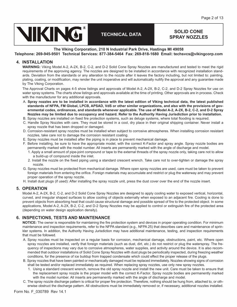
4. INSTALLATIONWARNING: Viking Model A-2, A-2X, B-2, C-2, and D-2 Solid Cone Spray Nozzles are manufactured and tested to meet the rigid requirements of the approving agency. The nozzles are designed to be installed in accordance with recognized installation stand-ards. Deviation from the standards or any alteration to the nozzle after it leaves the factory including, but not limited to: painting, plating, coating, or modification, may render the unit inoperative and will automatically nullify the approval and any guarantee made by The Viking Corporation.The Approval Charts on pages 4-5 show listings and approvals of Model A-2, A-2X, B-2, C-2, and D-2 Spray Nozzles for use on water spray systems. The charts show listings and approvals available at the time of printing. Other approvals are in process. Check with the manufacturer for any additional approvals. A. Spray nozzles are to be installed in accordance with the latest edition of Viking technical data, the latest published
standards of NFPA, FM Global, LPCB, APSAD, VdS or other similar organizations, and also with the provisions of gov-ernmental codes, ordinances, and standards whenever applicable. The use of Model A-2, A-2X, B-2, C-2, and D-2 Spray Nozzles may be limited due to occupancy and hazard. Refer to the Authority Having Jurisdiction prior to installation.
B. Spray nozzles are installed on fixed fire protection systems, such as deluge systems, where total flooding is required.C. Handle Spray Nozzles with care. They must be stored in a cool, dry place in their original shipping container. Never install a
spray nozzle that has been dropped or damaged.D. Corrosion-resistant spray nozzles must be installed when subject to corrosive atmospheres. When installing corrosion resistant
nozzles, take care not to damage the corrosion resistant coating. E. Spray nozzles must be installed after the piping is in place to prevent mechanical damage. F. Before installing, be sure to have the appropriate model, with the correct K-Factor and spray angle. Spray nozzle bodies are
permanently marked with the model number. All inserts are permanently marked with the angle of discharge and model. 1. Apply a small amount of pipe-joint compound or tape to the external threads of the spray nozzle only, taking care not to allow
a build-up of compound inside the inlet.2. Install the nozzle on the fixed piping using a standard crescent wrench. Take care not to over-tighten or damage the spray
nozzle. G. Spray nozzles must be protected from mechanical damage. Where open spray nozzles are used, care must be taken to prevent
foreign materials from entering the orifice. Foreign materials may accumulate and restrict or plug the waterway and may prevent proper operation of the spray nozzle.
H. Install dust plugs (if used): After installing the spray nozzle unit, press the dust cover over the end of the nozzle insert.
5. OPERATIONModel A-2, A-2X, B-2, C-2, and D-2 Solid Cone Spray Nozzles are designed to apply cooling water to exposed vertical, horizontal, curved, and irregular shaped surfaces to allow cooling of objects externally when exposed to an adjacent fire. Cooling is done to prevent objects from absorbing heat that could cause structural damage and possible spread of fire to the protected object. In some applications, Model A-2, A-2X, B-2, C-2, and D-2 Spray Nozzles may be applied to control or extinguish fire of the protected area (depending on water design application density).
6. INSPECTIONS, TESTS AND MAINTENANCENOTICE: The owner is responsible for maintaining the fire protection system and devices in proper operating condition. For minimum maintenance and inspection requirements, refer to the NFPA standard (e.g., NFPA 25) that describes care and maintenance of sprin-kler systems. In addition, the Authority Having Jurisdiction may have additional maintenance, testing, and inspection requirements that must be followed.A. Spray nozzles must be inspected on a regular basis for corrosion, mechanical damage, obstructions, paint, etc. Where open
spray nozzles are installed, verify that foreign materials (such as dust, dirt, etc.) do not restrict or plug the waterspray. The fre-quency of inspections may vary due to corrosive atmospheres, water supplies, and activity around the device. It is also recom-mended that outdoor installations of Solid Cone Spray Nozzles with dust plugs be periodically inspected, during freezing weather conditions, for the presence of ice buildup from trapped condensate which could effect the proper release of the plugs.
B. Spray nozzles that have been painted or mechanically damaged must be replaced immediately. Nozzles showing signs of corrosion shall be tested and/or replaced immediately as required. When replacing spray nozzles, use only new spray nozzles. 1. Using a standard crescent wrench, remove the old spray nozzle and install the new unit. Care must be taken to ensure that
the replacement spray nozzle is the proper model with the correct K-Factor. Spray nozzle bodies are permanently marked with the model number. All inserts are permanently marked with the angle of discharge and model.
C. The spray nozzle discharge pattern is critical for proper fire protection. Therefore, nothing should be hung from, attached to, or oth-erwise obstruct the discharge pattern. All obstructions must be immediately removed or, if necessary, additional nozzles installed.
SOLID CONE SPRAY NOZZLESTECHNICAL DATA
The Viking Corporation, 210 N Industrial Park Drive, Hastings MI 49058Telephone: 269-945-9501 Technical Services: 877-384-5464 Fax: 269-818-1680 Email: [email protected]
Form No. F_030789 Rev 14.1
Page 3 of 13
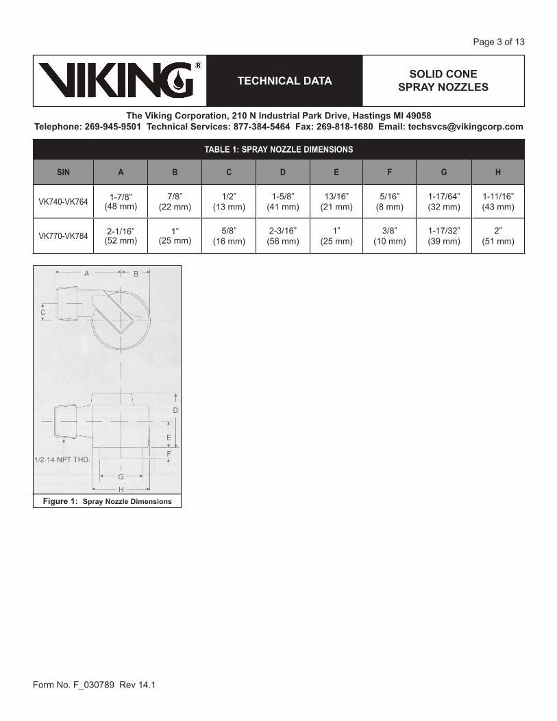
Figure 1: Spray Nozzle Dimensions
TABLE 1: SPRAY NOZZLE DIMENSIONS
SIN A B C D E F G H
VK740-VK764 1-7/8” (48 mm)
7/8” (22 mm)
1/2” (13 mm)
1-5/8” (41 mm)
13/16” (21 mm)
5/16” (8 mm)
1-17/64” (32 mm)
1-11/16” (43 mm)
VK770-VK784 2-1/16” (52 mm)
1” (25 mm)
5/8” (16 mm)
2-3/16” (56 mm)
1” (25 mm)
3/8” (10 mm)
1-17/32” (39 mm)
2” (51 mm)
SOLID CONE SPRAY NOZZLESTECHNICAL DATA
The Viking Corporation, 210 N Industrial Park Drive, Hastings MI 49058Telephone: 269-945-9501 Technical Services: 877-384-5464 Fax: 269-818-1680 Email: [email protected]
Form No. F_030789 Rev 14.1
Page 4 of 13
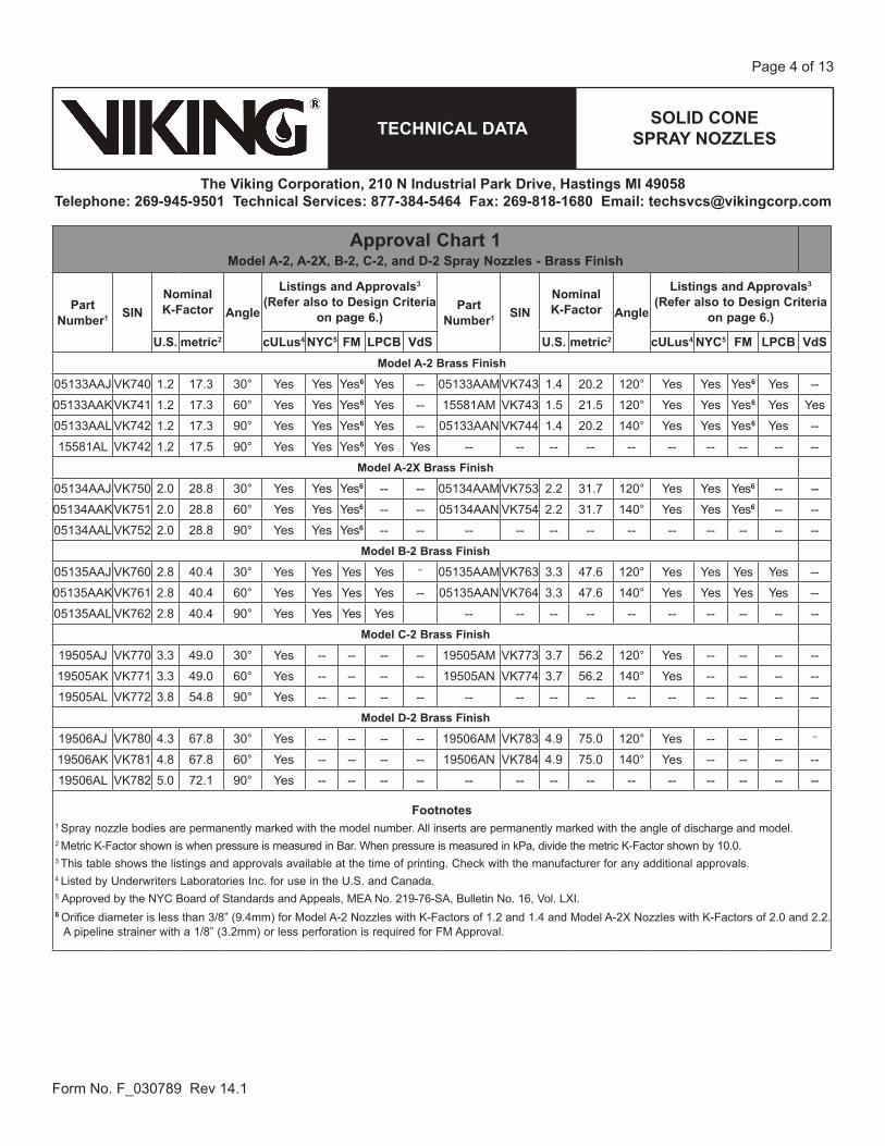
Approval Chart 1Model A-2, A-2X, B-2, C-2, and D-2 Spray Nozzles - Brass Finish
Part Number1 SIN
Nominal K-Factor Angle
Listings and Approvals3
(Refer also to Design Criteria on page 6.)
Part Number1 SIN
Nominal K-Factor Angle
Listings and Approvals3
(Refer also to Design Criteria on page 6.)
U.S. metric2 cULus4 NYC5 FM LPCB VdS U.S. metric2 cULus4 NYC5 FM LPCB VdSModel A-2 Brass Finish
05133AAJ VK740 1.2 17.3 30° Yes Yes Yes6 Yes -- 05133AAMVK743 1.4 20.2 120° Yes Yes Yes6 Yes --
05133AAKVK741 1.2 17.3 60° Yes Yes Yes6 Yes -- 15581AM VK743 1.5 21.5 120° Yes Yes Yes6 Yes Yes
05133AAL VK742 1.2 17.3 90° Yes Yes Yes6 Yes -- 05133AAN VK744 1.4 20.2 140° Yes Yes Yes6 Yes --
15581AL VK742 1.2 17.5 90° Yes Yes Yes6 Yes Yes -- -- -- -- -- -- -- -- -- --Model A-2X Brass Finish
05134AAJ VK750 2.0 28.8 30° Yes Yes Yes6 -- -- 05134AAMVK753 2.2 31.7 120° Yes Yes Yes6 -- --
05134AAKVK751 2.0 28.8 60° Yes Yes Yes6 -- -- 05134AAN VK754 2.2 31.7 140° Yes Yes Yes6 -- --
05134AAL VK752 2.0 28.8 90° Yes Yes Yes6 -- -- -- -- -- -- -- -- -- -- -- --Model B-2 Brass Finish
05135AAJ VK760 2.8 40.4 30° Yes Yes Yes Yes -- 05135AAMVK763 3.3 47.6 120° Yes Yes Yes Yes --
05135AAKVK761 2.8 40.4 60° Yes Yes Yes Yes -- 05135AAN VK764 3.3 47.6 140° Yes Yes Yes Yes --
05135AAL VK762 2.8 40.4 90° Yes Yes Yes Yes -- -- -- -- -- -- -- -- -- --Model C-2 Brass Finish
19505AJ VK770 3.3 49.0 30° Yes -- -- -- -- 19505AM VK773 3.7 56.2 120° Yes -- -- -- --
19505AK VK771 3.3 49.0 60° Yes -- -- -- -- 19505AN VK774 3.7 56.2 140° Yes -- -- -- --
19505AL VK772 3.8 54.8 90° Yes -- -- -- -- -- -- -- -- -- -- -- -- -- --Model D-2 Brass Finish
19506AJ VK780 4.3 67.8 30° Yes -- -- -- -- 19506AM VK783 4.9 75.0 120° Yes -- -- -- --
19506AK VK781 4.8 67.8 60° Yes -- -- -- -- 19506AN VK784 4.9 75.0 140° Yes -- -- -- --
19506AL VK782 5.0 72.1 90° Yes -- -- -- -- -- -- -- -- -- -- -- -- -- --
Footnotes1 Spray nozzle bodies are permanently marked with the model number. All inserts are permanently marked with the angle of discharge and model. 2 Metric K-Factor shown is when pressure is measured in Bar. When pressure is measured in kPa, divide the metric K-Factor shown by 10.0. 3 This table shows the listings and approvals available at the time of printing. Check with the manufacturer for any additional approvals.4 Listed by Underwriters Laboratories Inc. for use in the U.S. and Canada.5 Approved by the NYC Board of Standards and Appeals, MEA No. 219-76-SA, Bulletin No. 16, Vol. LXI.6 Orifice diameter is less than 3/8” (9.4mm) for Model A-2 Nozzles with K-Factors of 1.2 and 1.4 and Model A-2X Nozzles with K-Factors of 2.0 and 2.2.
A pipeline strainer with a 1/8” (3.2mm) or less perforation is required for FM Approval.
SOLID CONE SPRAY NOZZLESTECHNICAL DATA
The Viking Corporation, 210 N Industrial Park Drive, Hastings MI 49058Telephone: 269-945-9501 Technical Services: 877-384-5464 Fax: 269-818-1680 Email: [email protected]
Form No. F_030789 Rev 14.1
Page 5 of 13
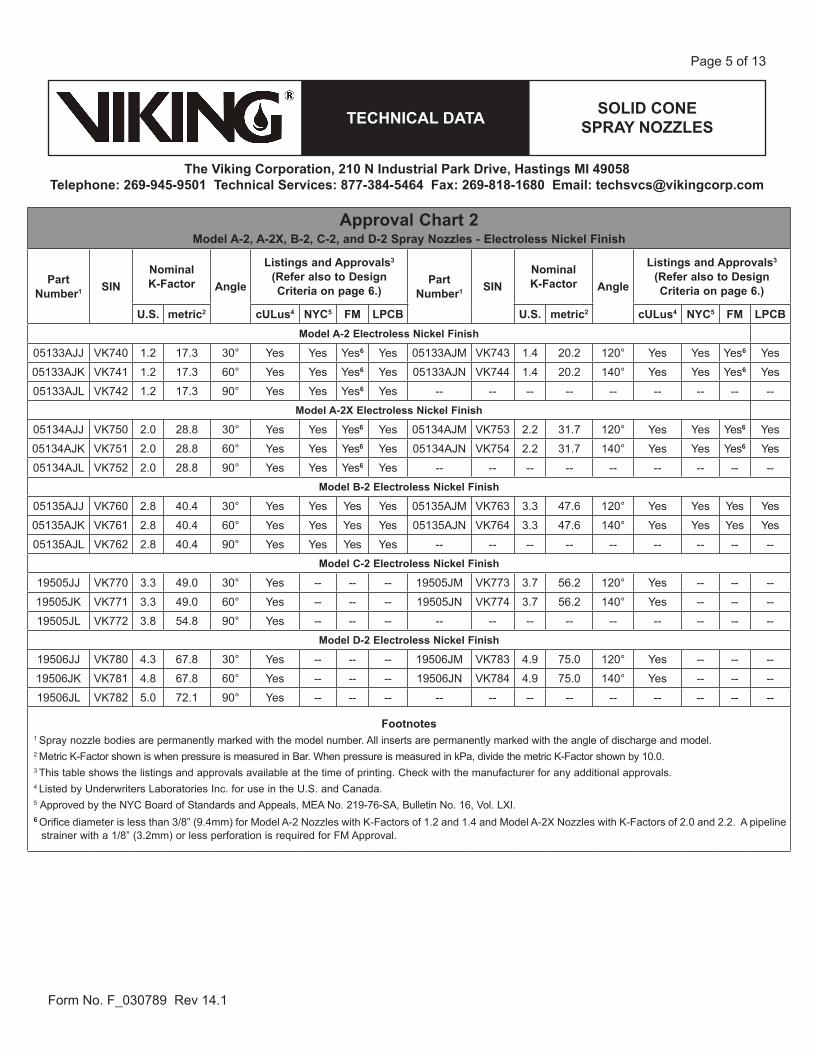
Approval Chart 2Model A-2, A-2X, B-2, C-2, and D-2 Spray Nozzles - Electroless Nickel Finish
Part Number1 SIN
Nominal K-Factor Angle
Listings and Approvals3
(Refer also to Design Criteria on page 6.)
Part Number1 SIN
Nominal K-Factor Angle
Listings and Approvals3
(Refer also to Design Criteria on page 6.)
U.S. metric2 cULus4 NYC5 FM LPCB U.S. metric2 cULus4 NYC5 FM LPCBModel A-2 Electroless Nickel Finish
05133AJJ VK740 1.2 17.3 30° Yes Yes Yes6 Yes 05133AJM VK743 1.4 20.2 120° Yes Yes Yes6 Yes
05133AJK VK741 1.2 17.3 60° Yes Yes Yes6 Yes 05133AJN VK744 1.4 20.2 140° Yes Yes Yes6 Yes
05133AJL VK742 1.2 17.3 90° Yes Yes Yes6 Yes -- -- -- -- -- -- -- -- --Model A-2X Electroless Nickel Finish
05134AJJ VK750 2.0 28.8 30° Yes Yes Yes6 Yes 05134AJM VK753 2.2 31.7 120° Yes Yes Yes6 Yes
05134AJK VK751 2.0 28.8 60° Yes Yes Yes6 Yes 05134AJN VK754 2.2 31.7 140° Yes Yes Yes6 Yes
05134AJL VK752 2.0 28.8 90° Yes Yes Yes6 Yes -- -- -- -- -- -- -- -- --Model B-2 Electroless Nickel Finish
05135AJJ VK760 2.8 40.4 30° Yes Yes Yes Yes 05135AJM VK763 3.3 47.6 120° Yes Yes Yes Yes
05135AJK VK761 2.8 40.4 60° Yes Yes Yes Yes 05135AJN VK764 3.3 47.6 140° Yes Yes Yes Yes
05135AJL VK762 2.8 40.4 90° Yes Yes Yes Yes -- -- -- -- -- -- -- -- --Model C-2 Electroless Nickel Finish
19505JJ VK770 3.3 49.0 30° Yes -- -- -- 19505JM VK773 3.7 56.2 120° Yes -- -- --
19505JK VK771 3.3 49.0 60° Yes -- -- -- 19505JN VK774 3.7 56.2 140° Yes -- -- --
19505JL VK772 3.8 54.8 90° Yes -- -- -- -- -- -- -- -- -- -- -- --Model D-2 Electroless Nickel Finish
19506JJ VK780 4.3 67.8 30° Yes -- -- -- 19506JM VK783 4.9 75.0 120° Yes -- -- --
19506JK VK781 4.8 67.8 60° Yes -- -- -- 19506JN VK784 4.9 75.0 140° Yes -- -- --
19506JL VK782 5.0 72.1 90° Yes -- -- -- -- -- -- -- -- -- -- -- --
Footnotes1 Spray nozzle bodies are permanently marked with the model number. All inserts are permanently marked with the angle of discharge and model. 2 Metric K-Factor shown is when pressure is measured in Bar. When pressure is measured in kPa, divide the metric K-Factor shown by 10.0. 3 This table shows the listings and approvals available at the time of printing. Check with the manufacturer for any additional approvals.4 Listed by Underwriters Laboratories Inc. for use in the U.S. and Canada.5 Approved by the NYC Board of Standards and Appeals, MEA No. 219-76-SA, Bulletin No. 16, Vol. LXI. 6 Orifice diameter is less than 3/8” (9.4mm) for Model A-2 Nozzles with K-Factors of 1.2 and 1.4 and Model A-2X Nozzles with K-Factors of 2.0 and 2.2. A pipeline
strainer with a 1/8” (3.2mm) or less perforation is required for FM Approval.
SOLID CONE SPRAY NOZZLESTECHNICAL DATA
The Viking Corporation, 210 N Industrial Park Drive, Hastings MI 49058Telephone: 269-945-9501 Technical Services: 877-384-5464 Fax: 269-818-1680 Email: [email protected]
Form No. F_030789 Rev 14.1
Page 6 of 13
D. Fire protection systems that have been subjected to a fire must be returned to service as soon as possible. The entire system must be inspected for damage and repaired or replaced as necessary. Spray nozzles that have been exposed to corrosive products of combustion or high ambient temperatures, should be replaced. Refer to the Authority Having Jurisdiction for minimum replacement requirements.
7. AVAILABILITYThe Viking Model A-2, A-2X, B-2, C-2, and D-2 Solid Cone Spray Nozzles are available through a network of domestic and inter-national distributors. See The Viking Corporation web site for the closest distributor or contact The Viking Corporation.
8. GUARANTEEFor details of warranty, refer to Viking’s current list price schedule or contact Viking directly.
DESIGN CRITERIA (Also refer to the Approval Charts on pages 4-5.)
cULus Listing Requirements: Refer to the installation standards, such as NFPA 15, for minimum water supply requirements, nozzle pressure, and installation guidelines.
FM Approval Requirements: For installation in accordance with the latest applicable FM Loss Prevention Data Sheets and Technical Advisory Bulletins. FM Global Loss Prevention Data Sheets and Technical Advisory Bulletins contain guidelines relating to, but not limited to: minimum water supply requirements, hydraulic design, ceiling slope and obstructions, minimum and maximum allowable spacing, and distance below the ceiling. Pipeline Strainers Orifice diameter is less than 3/8” (9.4mm) for Model A-2 Nozzles with K-Factors of 1.2 and 1.4 and Model A-2X Nozzles with K-Factors of 2.0 and 2.2. A pipeline strainer with a 1/8” (3.2mm) or less perforation is required for FM Approval.NOTE: The FM installation guidelines may differ from cULus and/or NFPA criteria.
IMPORTANT: Always refer to Bulletin Form No. F_091699 - Care and Handling of Sprinklers. Viking spray nozzles are to be installed in accordance with the latest edition of Viking technical data, the appropriate standards of NFPA, FM Global, LPCB, APSAD, VdS or other similar organizations, and also with the provisions of governmen-tal codes, ordinances, and standards, whenever applicable.
SOLID CONE SPRAY NOZZLES - WATER
DISTRIBUTION PATTERNSTECHNICAL DATA
The Viking Corporation, 210 N Industrial Park Drive, Hastings MI 49058Telephone: 269-945-9501 Technical Services 877-384-5464 Fax: 269-945-4495 Email: [email protected]
Form No. F_030789 Rev 14.1
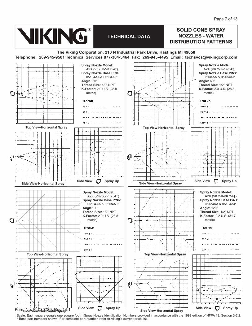
Page 7 of 13
Top View-Horizontal Spray
Spray Nozzle Model: A2X (VK750-VK754†)
Spray Nozzle Base P/Ns: 05134AA & 05134AJ*
Angle: 30°Thread Size: 1/2” NPTK-Factor: 2.0 U.S. (28.8
metric)
Side View-Horizontal SpraySide View Spray Up
Spray Nozzle Model: A2X (VK750-VK754†)
Spray Nozzle Base P/Ns: 05134AA & 05134AJ*
Angle: 60°Thread Size: 1/2” NPTK-Factor: 2.0 U.S. (28.8
metric)
Top View-Horizontal Spray
Side View-Horizontal SpraySide View Spray Up
Spray Nozzle Model: A2X (VK750-VK754†)
Spray Nozzle Base P/Ns: 05134AA & 05134AJ*
Angle: 90°Thread Size: 1/2” NPTK-Factor: 2.0 U.S. (28.8
metric)
Top View-Horizontal Spray
Side View-Horizontal SpraySide View Spray Up
Spray Nozzle Model: A2X (VK750-VK754†)
Spray Nozzle Base P/Ns: 05134AA & 05134AJ*
Angle: 120°Thread Size: 1/2” NPTK-Factor: 2.2 U.S. (31.7
metric)
Top View-Horizontal Spray
Side View-Horizontal SpraySide View Spray Up
Scale: Each square equals one square foot. †Spray Nozzle Identification Numbers provided in accordance with the 1999 edition of NFPA 13, Section 3-2.2.* Base part numbers shown. For complete part number, refer to Viking’s current price list.
SOLID CONE SPRAY NOZZLES - WATER
DISTRIBUTION PATTERNSTECHNICAL DATA
The Viking Corporation, 210 N Industrial Park Drive, Hastings MI 49058Telephone: 269-945-9501 Technical Services 877-384-5464 Fax: 269-945-4495 Email: [email protected]
Form No. F_030789 Rev 14.1
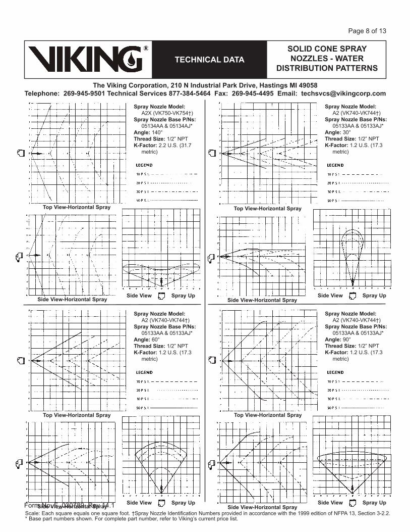
Page 8 of 13
Side View Spray Up
Top View-Horizontal Spray
Top View-Horizontal Spray
Side View Spray Up
Top View-Horizontal Spray
Spray Nozzle Model: A2X (VK750-VK754†)
Spray Nozzle Base P/Ns: 05134AA & 05134AJ*
Angle: 140°Thread Size: 1/2” NPTK-Factor: 2.2 U.S. (31.7
metric)
Top View-Horizontal Spray
Side View-Horizontal Spray
Spray Nozzle Model: A2 (VK740-VK744†)
Spray Nozzle Base P/Ns: 05133AA & 05133AJ*
Angle: 30°Thread Size: 1/2” NPTK-Factor: 1.2 U.S. (17.3
metric)
Side View-Horizontal SpraySide View Spray Up
Spray Nozzle Model: A2 (VK740-VK744†)
Spray Nozzle Base P/Ns: 05133AA & 05133AJ*
Angle: 60°Thread Size: 1/2” NPTK-Factor: 1.2 U.S. (17.3
metric)
Side View-Horizontal Spray
Spray Nozzle Model: A2 (VK740-VK744†)
Spray Nozzle Base P/Ns: 05133AA & 05133AJ*
Angle: 90°Thread Size: 1/2” NPTK-Factor: 1.2 U.S. (17.3
metric)
Side View-Horizontal SpraySide View Spray Up
Scale: Each square equals one square foot. †Spray Nozzle Identification Numbers provided in accordance with the 1999 edition of NFPA 13, Section 3-2.2.* Base part numbers shown. For complete part number, refer to Viking’s current price list.
SOLID CONE SPRAY NOZZLES - WATER
DISTRIBUTION PATTERNSTECHNICAL DATA
The Viking Corporation, 210 N Industrial Park Drive, Hastings MI 49058Telephone: 269-945-9501 Technical Services 877-384-5464 Fax: 269-945-4495 Email: [email protected]
Form No. F_030789 Rev 14.1
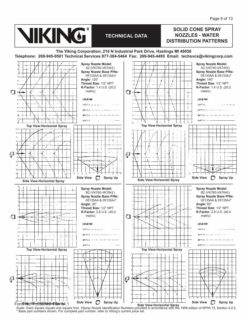
Page 9 of 13
Spray Nozzle Model: A2 (VK740-VK744†)
Spray Nozzle Base P/Ns: 05133AA & 05133AJ*
Angle: 120°Thread Size: 1/2” NPTK-Factor: 1.4 U.S. (20.2
metric)
Top View-Horizontal Spray
Side View-Horizontal SpraySide View Spray Up
Spray Nozzle Model: A2 (VK740-VK744†)
Spray Nozzle Base P/Ns: 05133AA & 05133AJ*
Angle: 140°Thread Size: 1/2” NPTK-Factor: 1.4 U.S. (20.2
metric)
Top View-Horizontal Spray
Side View-Horizontal SpraySide View Spray Up
Spray Nozzle Model: B2 (VK760-VK764†)
Spray Nozzle Base P/Ns: 05135AA & 05135AJ*
Angle: 30°Thread Size: 1/2” NPTK-Factor: 2.8 U.S. (40.4
metric)
Top View-Horizontal Spray
Side View-Horizontal Spray Side View Spray Up
Spray Nozzle Model: B2 (VK760-VK764†)
Spray Nozzle Base P/Ns: 05135AA & 05135AJ*
Angle: 60°Thread Size: 1/2” NPTK-Factor: 2.8 U.S. (40.4
metric)
Top View-Horizontal Spray
Side View-Horizontal SpraySide View Spray Up
Scale: Each square equals one square foot. †Spray Nozzle Identification Numbers provided in accordance with the 1999 edition of NFPA 13, Section 3-2.2.* Base part numbers shown. For complete part number, refer to Viking’s current price list.
SOLID CONE SPRAY NOZZLES - WATER
DISTRIBUTION PATTERNSTECHNICAL DATA
The Viking Corporation, 210 N Industrial Park Drive, Hastings MI 49058Telephone: 269-945-9501 Technical Services 877-384-5464 Fax: 269-945-4495 Email: [email protected]
Form No. F_030789 Rev 14.1
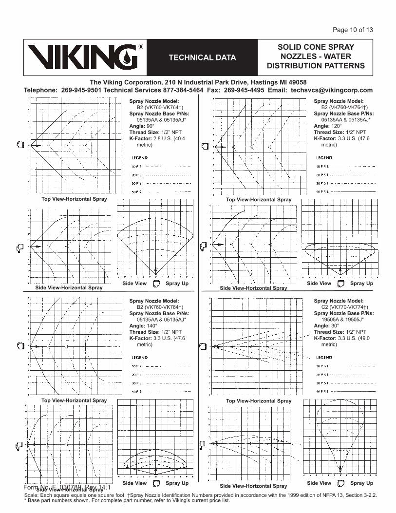
Page 10 of 13
Spray Nozzle Model: B2 (VK760-VK764†)
Spray Nozzle Base P/Ns: 05135AA & 05135AJ*
Angle: 90°Thread Size: 1/2” NPTK-Factor: 2.8 U.S. (40.4
metric)
Top View-Horizontal Spray
Side View-Horizontal SpraySide View Spray Up
Spray Nozzle Model: B2 (VK760-VK764†)
Spray Nozzle Base P/Ns: 05135AA & 05135AJ*
Angle: 120°Thread Size: 1/2” NPTK-Factor: 3.3 U.S. (47.6
metric)
Top View-Horizontal Spray
Side View-Horizontal SpraySide View Spray Up
Spray Nozzle Model: B2 (VK760-VK764†)
Spray Nozzle Base P/Ns: 05135AA & 05135AJ*
Angle: 140°Thread Size: 1/2” NPTK-Factor: 3.3 U.S. (47.6
metric)
Top View-Horizontal Spray
Side View-Horizontal SpraySide View Spray Up
Spray Nozzle Model: C2 (VK770-VK774†)
Spray Nozzle Base P/Ns: 19505A & 19505J*
Angle: 30°Thread Size: 1/2” NPTK-Factor: 3.3 U.S. (49.0
metric)
Top View-Horizontal Spray
Side View-Horizontal Spray Side View Spray Up
Scale: Each square equals one square foot. †Spray Nozzle Identification Numbers provided in accordance with the 1999 edition of NFPA 13, Section 3-2.2.* Base part numbers shown. For complete part number, refer to Viking’s current price list.
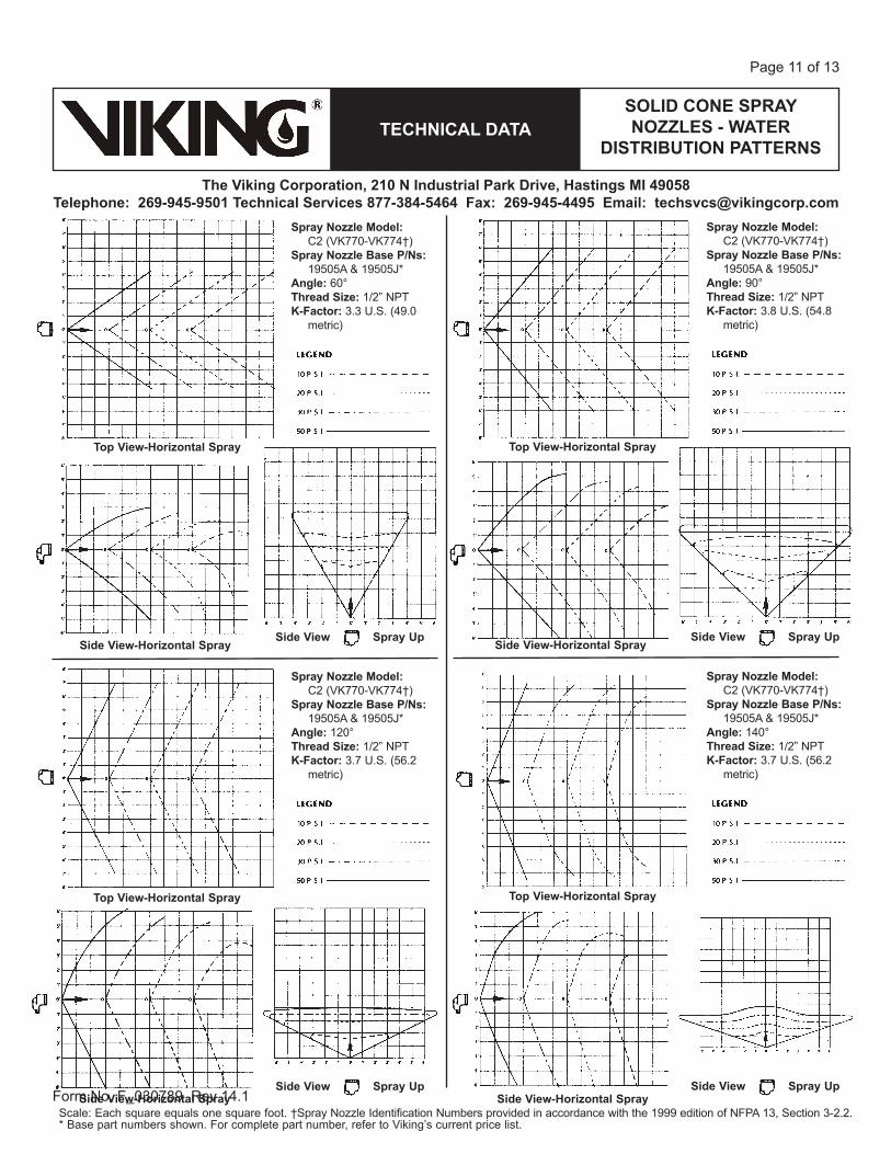
SOLID CONE SPRAY NOZZLES - WATER
DISTRIBUTION PATTERNSTECHNICAL DATA
The Viking Corporation, 210 N Industrial Park Drive, Hastings MI 49058Telephone: 269-945-9501 Technical Services 877-384-5464 Fax: 269-945-4495 Email: [email protected]
Form No. F_030789 Rev 14.1
Page 11 of 13
Spray Nozzle Model: C2 (VK770-VK774†)
Spray Nozzle Base P/Ns: 19505A & 19505J*
Angle: 60°Thread Size: 1/2” NPTK-Factor: 3.3 U.S. (49.0
metric)
Top View-Horizontal Spray
Side View-Horizontal SpraySide View Spray Up
Spray Nozzle Model: C2 (VK770-VK774†)
Spray Nozzle Base P/Ns: 19505A & 19505J*
Angle: 90°Thread Size: 1/2” NPTK-Factor: 3.8 U.S. (54.8
metric)
Top View-Horizontal Spray
Side View-Horizontal SpraySide View Spray Up
Spray Nozzle Model: C2 (VK770-VK774†)
Spray Nozzle Base P/Ns: 19505A & 19505J*
Angle: 120°Thread Size: 1/2” NPTK-Factor: 3.7 U.S. (56.2
metric)
Top View-Horizontal Spray
Side View-Horizontal SpraySide View Spray Up
Spray Nozzle Model: C2 (VK770-VK774†)
Spray Nozzle Base P/Ns: 19505A & 19505J*
Angle: 140°Thread Size: 1/2” NPTK-Factor: 3.7 U.S. (56.2
metric)
Top View-Horizontal Spray
Side View-Horizontal SpraySide View Spray Up
Scale: Each square equals one square foot. †Spray Nozzle Identification Numbers provided in accordance with the 1999 edition of NFPA 13, Section 3-2.2.* Base part numbers shown. For complete part number, refer to Viking’s current price list.
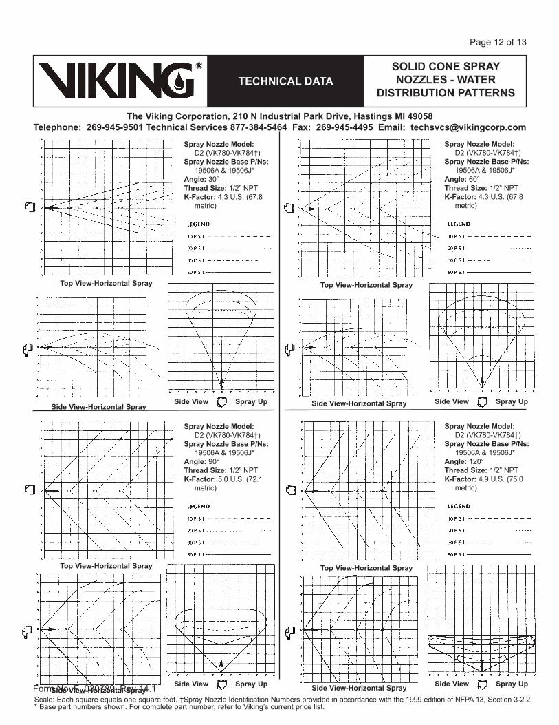
SOLID CONE SPRAY NOZZLES - WATER
DISTRIBUTION PATTERNSTECHNICAL DATA
The Viking Corporation, 210 N Industrial Park Drive, Hastings MI 49058Telephone: 269-945-9501 Technical Services 877-384-5464 Fax: 269-945-4495 Email: [email protected]
Form No. F_030789 Rev 14.1
Page 12 of 13
Spray Nozzle Model: D2 (VK780-VK784†)
Spray Nozzle Base P/Ns: 19506A & 19506J*
Angle: 30°Thread Size: 1/2” NPTK-Factor: 4.3 U.S. (67.8
metric)
Top View-Horizontal Spray
Side View-Horizontal SpraySide View Spray Up
Spray Nozzle Model: D2 (VK780-VK784†)
Spray Nozzle Base P/Ns: 19506A & 19506J*
Angle: 60°Thread Size: 1/2” NPTK-Factor: 4.3 U.S. (67.8
metric)
Top View-Horizontal Spray
Side View-Horizontal Spray Side View Spray Up
Spray Nozzle Model: D2 (VK780-VK784†)
Spray Nozzle Base P/Ns: 19506A & 19506J*
Angle: 90°Thread Size: 1/2” NPTK-Factor: 5.0 U.S. (72.1
metric)
Top View-Horizontal Spray
Side View-Horizontal SpraySide View Spray Up
Spray Nozzle Model: D2 (VK780-VK784†)
Spray Nozzle Base P/Ns: 19506A & 19506J*
Angle: 120°Thread Size: 1/2” NPTK-Factor: 4.9 U.S. (75.0
metric)
Top View-Horizontal Spray
Side View-Horizontal Spray Side View Spray Up
Scale: Each square equals one square foot. †Spray Nozzle Identification Numbers provided in accordance with the 1999 edition of NFPA 13, Section 3-2.2.* Base part numbers shown. For complete part number, refer to Viking’s current price list.
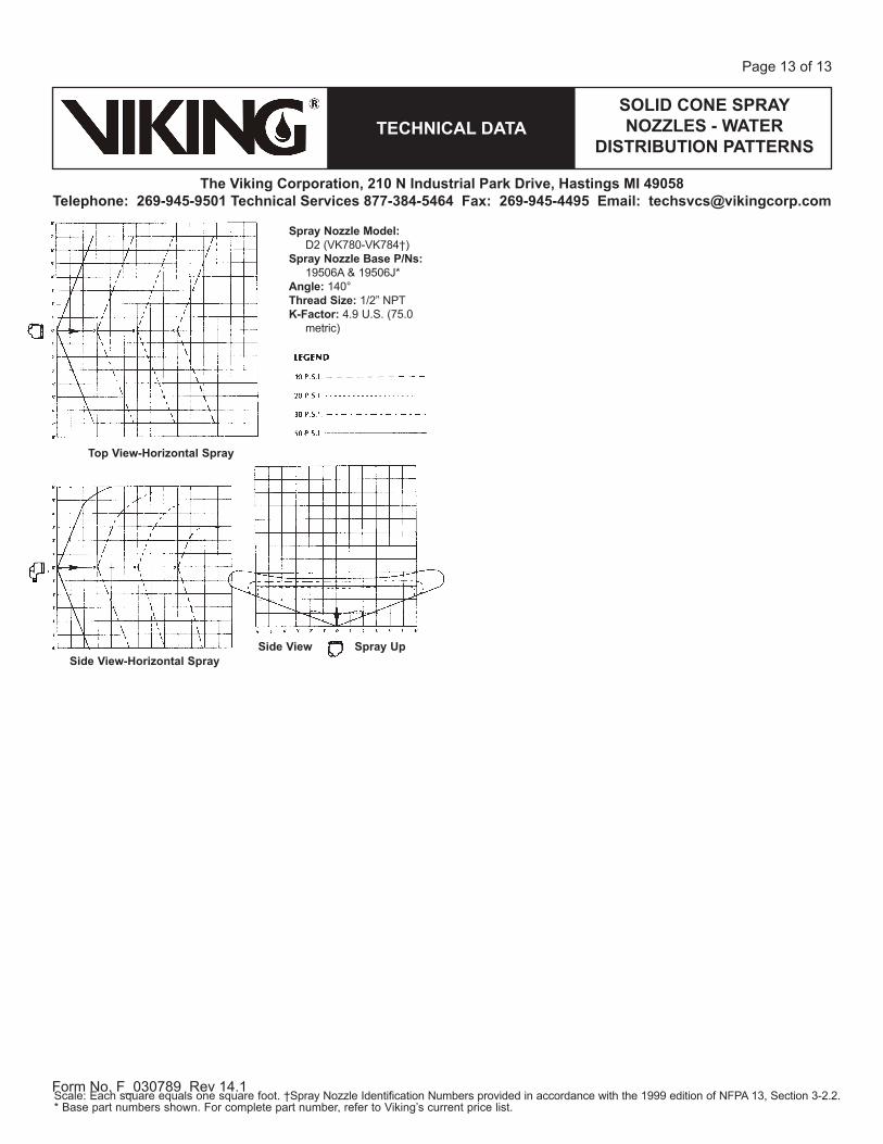
SOLID CONE SPRAY NOZZLES - WATER
DISTRIBUTION PATTERNSTECHNICAL DATA
The Viking Corporation, 210 N Industrial Park Drive, Hastings MI 49058Telephone: 269-945-9501 Technical Services 877-384-5464 Fax: 269-945-4495 Email: [email protected]
Form No. F_030789 Rev 14.1
Page 13 of 13
Spray Nozzle Model: D2 (VK780-VK784†)
Spray Nozzle Base P/Ns: 19506A & 19506J*
Angle: 140°Thread Size: 1/2” NPTK-Factor: 4.9 U.S. (75.0
metric)
Top View-Horizontal Spray
Side View-Horizontal SpraySide View Spray Up
Scale: Each square equals one square foot. †Spray Nozzle Identification Numbers provided in accordance with the 1999 edition of NFPA 13, Section 3-2.2.* Base part numbers shown. For complete part number, refer to Viking’s current price list.