Embed Size (px)
Citation preview
CHAPTER 10
PRECISION GRINDING MACHINES
CHAPTER LEARNING OBJECTIVES
Upon completing this chapter, you should be able to do the following:
Describe speeds, feeds, and coolants used while grinding.
Describe and explain the use of surface grinders.
Describe and explain the use of cylindrical grinders.
Describe and explain the use of tool and cutter grinders.
Modern grinding machines are versatile and areused to perform work of extreme accuracy. They areused primarily to finish surfaces that have beenmachined in other machine tool operations. Surfacegrinders, cylindrical grinders, and tool and cuttergrinders can perform practically all of the grindingoperations required in Navy repair work.
To perform these operations, you must know theconstruction and principles of operation of commonlyused grinding machines. You gain proficiency ingrinding through practical experience. Therefore, youshould take every opportunity to watch or performgrinding operations from setup to completion.
There are several classes of each type of grinder.The SURFACE grinder may have either a rotary or areciprocating table and either a horizontal or a verticalspindle. CYLINDRICAL grinders may be classified asplain, centerless, or internal grinders; the TOOL ANDCUTTER grinder is basically a cylindrical grinder.Those generally found in Navy machine shops are thereciprocating table grinder, the horizontal spindle(planer type) surface grinder, the plain cylindricalgrinder, and the tool and cutter grinder. Shops also mayhave a universal grinder, which is similar to a tool andcutter grinder except that it is designed for heavier workand usually has a power feed system and a coolantsystem.
Before operating a grinding machine, you mustunderstand the underlying principles of grinding andthe purpose and operation of the various controls andparts of the machine. You also must know how to set
up the work in the machine. The setup procedures willvary with the different models and types of machines.Study the manufacturer’s technical manual to learnspecific procedures for a particular model of machine.
As with any shop equipment you must observe allposted safety precautions. Review your equipmentoperators manual for safety precautions and anychapters of Navy Occupational Safety and Health(NAVOSH) Program Manual for Forces Afloat,OPNAV Instruction 5100.19B, that apply to theequipment.
GRAIN DEPTH OF CUT
On most ships, stowage space is limited. Con-sequently, the inventory of grinding wheels must bekept to a minimum. It would be impractical andunnecessary to keep on hand a wheel for every grindingjob. With a knowledge of the theory of grain depth ofcut you can vary the cutting action of the various wheelsand with a small inventory can perform practically anygrinding operation that may be necessary.
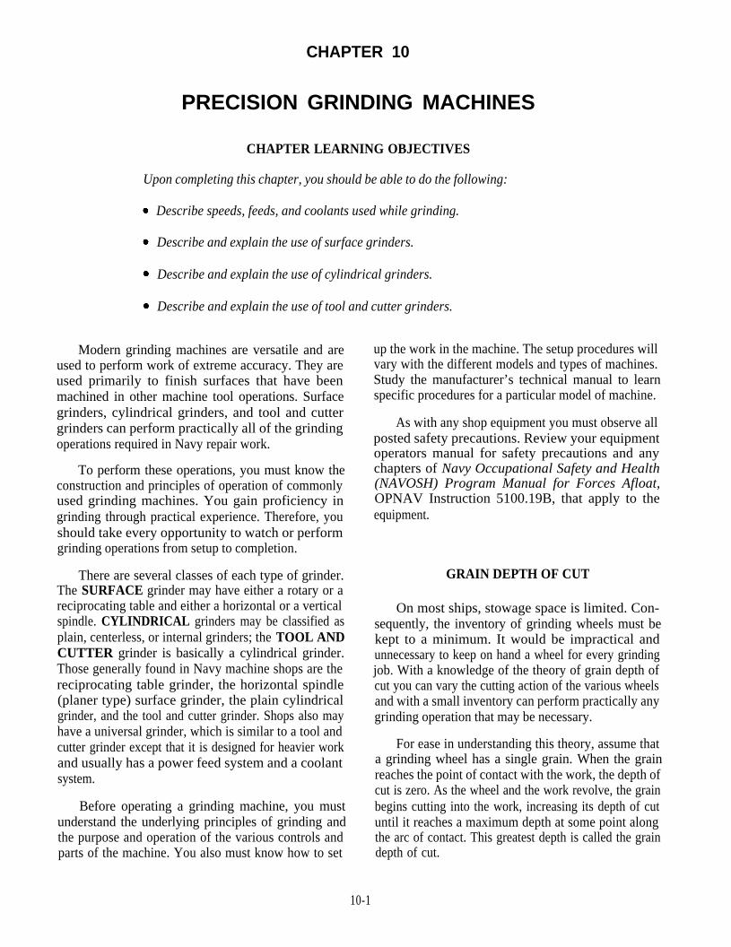
For ease in understanding this theory, assume thata grinding wheel has a single grain. When the grainreaches the point of contact with the work, the depth ofcut is zero. As the wheel and the work revolve, the grainbegins cutting into the work, increasing its depth of cutuntil it reaches a maximum depth at some point alongthe arc of contact. This greatest depth is called the graindepth of cut.
10-1
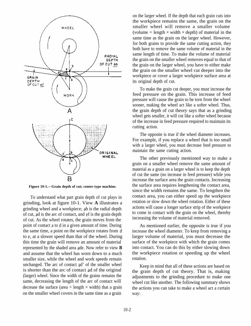
Figure 10-1.—Grain depth of cut; center-type machine.
To understand what part grain depth of cut plays ingrinding, look at figure 10-1. View A illustrates agrinding wheel and a workpiece; ab is the radial depthof cut, ad is the arc of contact, and ef is the grain depthof cut. As the wheel rotates, the grain moves from thepoint of contact a to d in a given amount of time. Duringthe same time, a point on the workpiece rotates from dto e, at a slower speed than that of the wheel. Duringthis time the grain will remove an amount of materialrepresented by the shaded area ade. Now refer to view Band assume that the wheel has worn down to a muchsmaller size, while the wheel and work speeds remainunchanged. The arc of contact ad’ of the smaller wheelis shorter than the arc of contact ad of the original(larger) wheel. Since the width of the grains remains thesame, decreasing the length of the arc of contact willdecrease the surface (area = length × width) that a grainon the smaller wheel covers in the same time as a grain
on the larger wheel. If the depth that each grain cuts intothe workpiece remains the same, the grain on thesmaller wheel will remove a smaller volume(volume = length × width × depth) of material in thesame time as the grain on the larger wheel. However,for both grains to provide the same cutting action, theyboth have to remove the same volume of material in thesame length of time. To make the volume of materialthe grain on the smaller wheel removes equal to that ofthe grain on the larger wheel, you have to either makethe grain on the smaller wheel cut deeper into theworkpiece or cover a larger workpiece surface area atits original depth of cut.
To make the grain cut deeper, you must increase thefeed pressure on the grain. This increase of feedpressure will cause the grain to be torn from the wheelsooner, making the wheel act like a softer wheel. Thus,the grain depth of cut theory says that as a grindingwheel gets smaller, it will cut like a softer wheel becauseof the increase in feed pressure required to maintain itscutting action.
The opposite is true if the wheel diameter increases.For example, if you replace a wheel that is too smallwith a larger wheel, you must decrease feed pressure tomaintain the same cutting action.
The other previously mentioned way to make agrain on a smaller wheel remove the same amount ofmaterial as a grain on a larger wheel is to keep the depthof cut the same (no increase in feed pressure) while youincrease the surface area the grain contacts. Increasingthe surface area requires lengthening the contact area,since the width remains the same. To lengthen thecontact area, you can either speed up the workpiecerotation or slow down the wheel rotation. Either of theseactions will cause a longer surface strip of the workpieceto come in contact with the grain on the wheel, therebyincreasing the volume of material removed.
As mentioned earlier, the opposite is true if youincrease the wheel diameter. To keep from removing alarger volume of material, you must decrease thesurface of the workpiece with which the grain comesinto contact. You can do this by either slowing downthe workpiece rotation or speeding up the wheelrotation.
Keep in mind that all of these actions are based onthe grain depth of cut theory. That is, makingadjustments to the grinding procedure to make onewheel cut like another. The following summary showsthe actions you can take to make a wheel act a certainway:
10-2
MAKE THE WHEEL ACT SOFTER (INCREASETHE GRAIN DEPTH OF CUT)
Increase the work speed.
Decrease the wheel speed.
Reduce the diameter of the wheel and increasefeed pressure.
MAKE THE WHEEL ACT HARDER (DE-CREASE THE GRAIN DEPTH OF CUT)
Decrease the work speed.
Increase the wheel speed.
Figure 10-2.—Surface grinding a flat workpiece.
Increase the diameter of the wheel and decreasefeed pressure.
SPEEDS, FEEDS, AND COOLANTS
As with other machine tools, the selection of theproper speed, feed, and depth of cut is an importantfactor in grinding. Also, coolants may be necessary forsome operations. The definitions of the terms speed,feed, and depth of cut, as applied to grinding, arebasically the same as those in other machiningoperations.
WHEEL SPEED, unless otherwise defined, meansthe surface speed of the grinding wheel in fpm.TRAVERSE (longitudinal or cross) is the rate that thework is moved across the working face of the grindingwheel. FEED is the depth of cut the wheel takes in eachpass across the work. We’ll explain each of these in thenext paragraphs
WHEEL SPEED
Grinding wheel speeds commonly used in precisiongrinding vary from 5,500 to 9,500 fpm. You can changewheel speed by changing the spindle speed or by usinga larger or smaller wheel. To find the wheel speed infpm, multiply the spindle speed (rpm) by the wheelcircumference (inches) and divide the product by 12.
The maximum speed listed on a grinding wheel isnot necessarily the speed at which it will cut best. Themanufacturer decides the maximum speed based on thestrength of the wheel. That speed provides a margin ofsafety and the wheel usually will cut better at a lowerspeed.
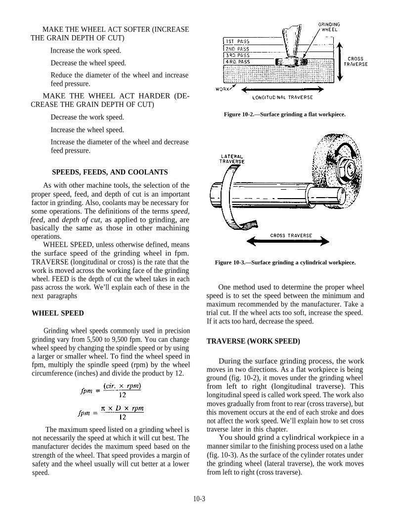
Figure 10-3.—Surface grinding a cylindrical workpiece.
One method used to determine the proper wheelspeed is to set the speed between the minimum andmaximum recommended by the manufacturer. Take atrial cut. If the wheel acts too soft, increase the speed.If it acts too hard, decrease the speed.
TRAVERSE (WORK SPEED)
During the surface grinding process, the workmoves in two directions. As a flat workpiece is beingground (fig. 10-2), it moves under the grinding wheelfrom left to right (longitudinal traverse). Thislongitudinal speed is called work speed. The work alsomoves gradually from front to rear (cross traverse), butthis movement occurs at the end of each stroke and doesnot affect the work speed. We’ll explain how to set crosstraverse later in this chapter.
You should grind a cylindrical workpiece in amanner similar to the finishing process used on a lathe(fig. 10-3). As the surface of the cylinder rotates underthe grinding wheel (lateral traverse), the work movesfrom left to right (cross traverse).
10-3

To select the proper work speed, take a cut with thework speed set at 50 fpm. If the wheel acts too soft,decrease the work speed. If the wheel acts too hard,increase the work speed.
Wheel speed and work speed are closely related.Usually, you can adjust one or both to get the mostsuitable combination.
DEPTH OF CUT
The depth of cut depends on such factors as thematerial from which the work is made, heat treatment,wheel and work speed, and condition of the machine.Roughing cuts should be as heavy as the machine cantake; finishing cuts are usually 0.0005 inch or less. Forrough grinding, you might use a 0.003-inch depth of cutas a trial. Then, adjust the machine until you get the bestcutting action.
COOLANTS
The cutting fluids used in grinding operations arethe same as hose used in other machine tool operations.Synthetic coolants are the best, but you also may use amixture of soluble oil and water. As in most machiningoperations, the coolant helps to maintain a uniformtemperature between the tool and the work to preventextreme localized heating. Excessive heat will damagethe edges of cutters, cause warpage, and may causeinaccurate measurements.
In other machine tool operations, the chips will fallaside and present no great problem; this is not true ingrinding work. If you have no way to remove chips, theycan become embedded in the face of the wheel. Thisembedding, or loading, will cause unsatisfactorygrinding and you will need to dress the wheelfrequently. A sufficient volume of cutting fluid willhelp prevent loading. The fluid also helps to reducefriction between the wheel and the work and to producea good finish. When you select a cutting fluid for agrinding operation, it should have the followingcharacteristics:
Have a high cooling capacity to reduce cuttingtemperature
Prevent chips from sticking to the work
Be suitable for a variety of machine operationson different materials, reducing the number of cuttingfluids needed in the shop
Have long life and not emit obnoxious odors orvapors harmful to personnel
Figure 10-4.—Overlapping disk balancing ways (roller type).
Not cause rust or corrosion
Have a low viscosity to permit gravity separationof impurities and chips as it is circulated in the coolingsystem
Not oxidize or form gummy deposits that willclog the circulating system
Be transparent, allowing a clear view of the work
Be safe, particularly in regard to fire and accidenthazards
Not cause skin irritation
The principles discussed above are basic toprecision grinding machines. Keep them in mind as youstudy about the machines in the remainder of thischapter.
WHEEL BALANCING
You may need to balance wheels larger than 14inches, but usually not smaller ones. A wheel that isslightly out of balance may cause chatter marks in theworkpiece finish. One that is drastically out of balancemay damage the grinder or fly apart and injure theoperator.
You should balance grinding wheels on either theoverlapping disk balancing ways (roller type) (fig.10-4) or on parallel ways (knife edge) (fig. 10-5). Setthese stands as level as possible, mount the wheel on abalancing arbor, and place it on the rollers or ways. Theheavy side will rotate to the lowest position. Adjust
10-4

Figure 10-5.—Parallel ways (knife edge).
Figure 10-6.—Balance weights.
weights in the flanges (fig. 10-6) to get the correctbalance.
SURFACE GRINDER
Most of the features shown in figure 10-7 arecommon to all planer-type surface grinders. The basiccomponents of this machine are a base, a cross traversetable, a sliding worktable, and a wheelhead. Variouscontrols and handwheels control the movement of themachine during the grinding operation.
The base is a heavy casting that houses thewheelhead motor, the hydraulic power feed unit, and thecoolant system. Use the ways on top of the base tomount the cross traverse table. Use the vertical ways onthe back of the base to mount the wheelhead unit.
The hydraulic power unit includes a motor, a pump,and piping. These provide hydraulic pressure to thepower feed mechanisms on the cross traverse and
Figure 10-7.—Surface grinder (planer type).
sliding tables. This smooth, direct power is veryadvantageous in grinding. The piping from this unit isusually connected to power cylinders under the traversetable. When the machine is operating automatically,control valves divert pressurized hydraulic fluid to theproper cylinder, causing the table to move in the desireddirection. Suitable bypass and control valves in thehydraulic system let you stop the traverse table in anyposition and regulate the speed of movement of the tablewithin limits. These valves provide a constant pressurein the hydraulic system, allowing you to stop the feedwithout securing the system.
CROSS TRAVERSE TABLE
The cross traverse table is mounted on ways that areparallel to the spindle of the wheelhead unit. This allowsthe entire width of the workpiece to be traversed underthe grinding wheel.
A piston in a power cylinder is fastened to the crosstraverse table to provide power feed. A handwheelattached to a feed screw provides manual feed. Thethickness (width) of the grinding wheel determines theamount of cross traverse feed per stroke of thereciprocating sliding table. During roughing cuts, thework should traverse slightly less than the thickness ofthe wheel each time it passes under the wheel. For finishcuts, decrease the rate until you obtain the desired finish.When you engage the power feed mechanism, the crosstraverse table feeds only at each end of the stroke of the
10-5

Figure 10-8.—Magnetic chuck used for holding a tool grinding fixture.
sliding table (discussed in the next paragraphs). Thegrinding wheel clears the ends of the workpiece beforecross-feed is made; this decreases side thrust on thegrinding wheel and prevents a poor surface finish on theends of the workpiece.
Grinding machines in shipboard shops usually have12 inches or less of cross traverse. It isn’t necessary totraverse the full limit for each job. To limit the crosstraverse to the width of the work being ground, use theadjustable cross traverse stop dogs that actuate thepower cross traverse control valves.
SLIDING TABLE
The sliding table is mounted on ways on the top ofthe cross traverse table. Recall that the sliding tablemoves from left to right, carrying the workpiece underthe grinding wheel.
The top of the sliding table has T-slots machined init so you can clamp work or workholding devices likemagnetic chucks or vises onto the table. You cantraverse the sliding table manually or by power.
The power feed of the table is similar to that of thecross traverse table. During manual traverse, a pinionturned by a handwheel engages a rack attached to thebottom of the sliding table.
During manual operation of the sliding table, tablestop dogs limit the length of stroke. When power feed
is used, table reverse dogs reverse the direction ofmovement of the table at each end of the stroke. Thereverse dogs actuate the control valve to shift thehydraulic feed pressure from one end of the powercylinder to the other.
You can usually adjust the speed (fpm) of the slidingtable within a wide range to give the most suitablespeed.
WHEELHEAD
The wheelhead carries the motor-driven grindingwheel spindle. You can adjust the wheelhead verticallyto feed the grinding wheel into the work by turning alead screw type of mechanism similar to that used onthe cross traverse table. A graduated collar on thehandwhcel lets you keep track of the depth of cut.
The wheelhead movement is not usually power fedbecause the depth of cut is quite small and you needlarge movement only to set up the machine. Theadjusting mechanism is quite sensitive; you can adjustthe depth of cut in amounts as small as 0.0001 inch.
WORKHOLDING DEVICES
In most surface grinding operations, you will useone of two workholding devices, either a magnetic
10-6

chuck or a universal vise. We will discuss each of themin the next paragraphs.
Magnetic Chucks
Since most surface grinding is done on flatworkpieces, most surface grinders have magneticchucks. These chucks are simple to use. You can mountthe work directly on the chuck or on angle plates,parallels, or other devices mounted on the chuck Youcannot hold nonmagnetic materials in a chuck unlessyou use special setups.
The top of a magnetic chuck (see fig. 10-8) is aseries of magnetic poles separated by nonmagneticmaterials. The magnetism of the chuck may be inducedby permanent magnets or by electricity. In apermanent-type magnetic chuck, the chuck controllever positions a series of small magnets inside thechuck to hold the work In an electromagnetic chuck,electric current induces magnetism in the chuck; thecontrol lever is an electric switch. For either chuck,work will not remain in place unless it contacts at leasttwo poles of the chuck.
Work held in a magnetic chuck may becomemagnetized during the grinding operation. This is notusually desirable and the work should be demagnetized.Most modern magnetic chucks are equipped withdemagnetizers.
A magnetic chuck will become worn and scratchedafter repeated use and will not produce the accurateresults normally required of a grinder. You can removesmall burrs by hand stoning with a fine grade oilstone.But, you must regrind the chuck to remove deepscratches and low spots caused by wear. If you removethe chuck from the grinder, be sure to regrind the chucktable when you replace the chuck to make sure the tableis parallel with the grinder table. To grind the table, usea soft grade wheel with a grit size of about 46. Feed thechuck slowly with a depth of cut that does not exceed0.002 inch. Use enough coolant to help reduce heat andflush away the grinding chips.
Universal Vise
You will usually use the universal vise (fig. 10-9)when you need to grind complex angles on a workpiece.You can mount the vise directly on the worktable of thegrinder or on the magnetic chuck.
You can use the universal vise to set up work, suchas lathe tools, so you can position the surface to beground at any angle. The swivels rotate through 360°.You can rotate the base swivel (A, fig. 10-9) in ahorizontal plane; the intermediate swivel (B, fig. 10-9)
28.251Figure 10-9.—Universal vise (mounted on a tool and cutter
grinder). A. Base swivel. B. Intermediate swivel. C. Viseswivel.
28.256Figure 10-10.—Grinding a spacer on a surface grinder.
in a vertical plane; and the vise swivel (C, fig. 10-9) ineither a vertical or a horizontal plane, depending on theposition of the intermediate swivel.
SURFACE GRINDER OPERATION
We will use a hardened steel spacer similar to theone shown in figure 10-10 as an example of work you
10-7

can do on a surface grinder. Use the followingprocedures:
1. Place the workpiece on the magnetic chuck.Move the chuck lever to the position that energizes themagnetic field.
2. Select and mount an appropriate grindingwheel. This job requires a straight-type wheel with adesignation similar to A60F12V.
3. Set the table stop dogs so the sliding table willmove the work clear of the wheel at each end of thestroke. If you use power traverse, set the table reversedogs.
4. Set the longitudinal traverse speed of theworktable. To rough grind hardened steel, use a speedof about 25 fpm; to finish the piece, use 40 fpm.
5. Set the cross traverse mechanism so the tablemoves under the wheel a distance slightly less than thewidth of the wheel after each pass. (Refer to themanufacturer’s technical manual for specificprocedures for steps 4 and 5.)
6. Start the spindle motor, let the machine run fora few minutes, and then dress the wheel.
7. Feed the moving wheel down until it justtouches the work surface; then use the manual crosstraverse handwheel to move the work clear of the wheel.Set the graduated feed collar on zero to keep track ofhow much you feed the wheel into the work.
8. Feed the wheel down about 0.002 inch andengage the longitudinal power traverse. Use the crosstraverse handwheel to bring the grinding wheel intocontact with the edge of the workpiece.
9. Engage the power cross traverse and let thewheel grind across the surface of the workpiece.Carefully note the cutting action to decide if you needto adjust the wheel speed or the work speed.
10. Stop the longitudinal and cross traverses andcheck the workpiece.
Figure 10-9 shows a universal vise being used on atool and cutter grinder to grind a lathe tool bit. For thisjob, set the base swivel (A) to the required side cuttingedge angle, the intermediate swivel (B) to the sideclearance angle, and the vise swivel (C) so the vise jawsare parallel to the table. Then, use a cup-type wheel togrind the side of the tool. Reset the universal vise to cutthe end and top of the tool after the side is ground.
You can use the universal vise on a surface grinderfor very accurate grinding of lathe cutting tools such as
threading tools. For example, to grind an Acmethreading tool, set the vise swivel at 14 1/2° fromparallel to the table. Set the intermediate swivel to theclearance angle. Set the base swivel so the tool blank(held in the vise jaws) is parallel to the spindle of thegrinder. Remember to leave the tool blank extending farenough out of the end of the vise jaws to prevent thegrinding wheel from hitting the vise. After grinding oneside of the tool bit, turn it one-half turn in the vise andset the intermediate swivel to an equal but oppositeangle to the angle set for the first side. This setting willresult in a clearance equal to the clearance of the firstside.
Another method for grinding single-point tools isto hold the tool in a special fixture, as shown in figure10-8. The fixture surfaces are cut at the angles necessaryto hold the tool so the angles of the tool bit are formedproperly.
When you use either method to grind tool bits,check the bit occasionally with an appropriate gaugeuntil you have the correct dimensions. To save time,rough grind the bit to approximate size on a benchgrinder before you set it in the jig.
CYLINDRICAL GRINDER
The cylindrical grinder is used to grind work suchas round shafts. Although many of the constructionfeatures of the cylindrical grinder are similar to those ofthe surface grinder, there is a considerable difference inthe functions of the components. Cylindrical grindershave no cross traverse table. An additional piece ofequipment (the workhead) is mounted on the slidingtable, and the wheelhead spindle is parallel to the slidingtable. See figure 10-11.
As in the surface grinder, the base of this machinecontains a hydraulic power unit and a coolant system.Longitudinal ways support the sliding table. Horizontalways (at right angles to the longitudinal ways) permitthe wheelhead to move toward or away from theworkpiece. You will use this horizontal movement tofeed the grinding wheel into the work for a depth of cut.
SLIDING TABLE
The sliding table of the cylindrical grinder ismounted directly on the longitudinal ways. This tablemoves back and forth to traverse the worklongitudinally along the width of the grinding wheel.
An adjustable taper table, located on top of thesliding table is used to grind long (small angle) tapers
10-8
28.252
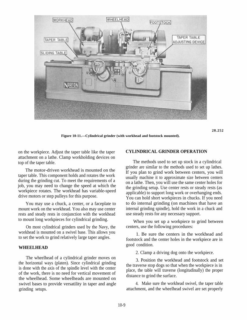
Figure 10-11.—Cylindrical grinder (with workhead and footstock mounted).
on the workpiece. Adjust the taper table like the taperattachment on a lathe. Clamp workholding devices ontop of the taper table.
The motor-driven workhead is mounted on thetaper table. This component holds and rotates the workduring the grinding cut. To meet the requirements of ajob, you may need to change the speed at which theworkpiece rotates. The workhead has variable-speeddrive motors or step pulleys for this purpose.
You may use a chuck, a center, or a faceplate tomount work on the workhead. You also may use centerrests and steady rests in conjunction with the workheadto mount long workpieces for cylindrical grinding.
On most cylindrical grinders used by the Navy, theworkhead is mounted on a swivel base. This allows youto set the work to grind relatively large taper angles.
WHEELHEAD
The wheelhead of a cylindrical grinder moves onthe horizontal ways (platen). Since cylindrical grindingis done with the axis of the spindle level with the centerof the work, there is no need for vertical movement ofthe wheelhead. Some wheelheads are mounted onswivel bases to provide versatility in taper and anglegrinding setups.
CYLINDRICAL GRINDER OPERATION
The methods used to set up stock in a cylindricalgrinder are similar to the methods used to set up lathes.If you plan to grind work between centers, you willusually machine it to approximate size between centerson a lathe. Then, you will use the same center holes forthe grinding setup. Use center rests or steady rests (asapplicable) to support long work or overhanging ends.You can hold short workpieces in chucks. If you needto do internal grinding (on machines that have aninternal grinding spindle), hold the work in a chuck anduse steady rests for any necessary support.
When you set up a workpiece to grind betweencenters, use the following procedures:
1. Be sure the centers in the workhead andfootstock and the center holes in the workpiece are ingood condition.
2. Clamp a driving dog onto the workpiece.
3. Position the workhead and footstock and setthe traverse stop dogs so that when the workpiece is inplace, the table will traverse (longitudinally) the properdistance to grind the surface.
4. Make sure the workhead swivel, the taper tableattachment, and the wheelhead swivel are set properly
10-9
28.253
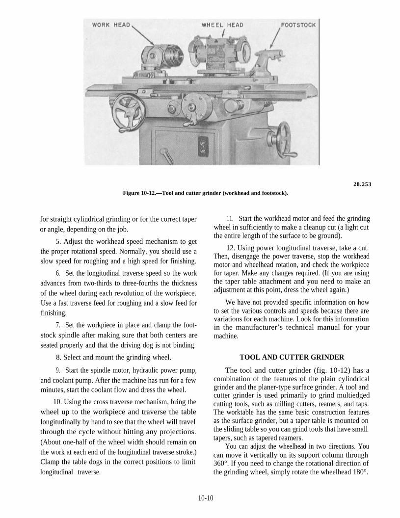
Figure 10-12.—Tool and cutter grinder (workhead and footstock).
for straight cylindrical grinding or for the correct taperor angle, depending on the job.
5. Adjust the workhead speed mechanism to getthe proper rotational speed. Normally, you should use aslow speed for roughing and a high speed for finishing.
6. Set the longitudinal traverse speed so the workadvances from two-thirds to three-fourths the thicknessof the wheel during each revolution of the workpiece.Use a fast traverse feed for roughing and a slow feed forfinishing.
7. Set the workpiece in place and clamp the foot-stock spindle after making sure that both centers areseated properly and that the driving dog is not binding.
8. Select and mount the grinding wheel.
9. Start the spindle motor, hydraulic power pump,and coolant pump. After the machine has run for a fewminutes, start the coolant flow and dress the wheel.
10. Using the cross traverse mechanism, bring thewheel up to the workpiece and traverse the tablelongitudinally by hand to see that the wheel will travelthrough the cycle without hitting any projections.(About one-half of the wheel width should remain onthe work at each end of the longitudinal traverse stroke.)Clamp the table dogs in the correct positions to limitlongitudinal traverse.
11. Start the workhead motor and feed the grindingwheel in sufficiently to make a cleanup cut (a light cutthe entire length of the surface to be ground).
12. Using power longitudinal traverse, take a cut.Then, disengage the power traverse, stop the workheadmotor and wheelhead rotation, and check the workpiecefor taper. Make any changes required. (If you are usingthe taper table attachment and you need to make anadjustment at this point, dress the wheel again.)
We have not provided specific information on howto set the various controls and speeds because there arevariations for each machine. Look for this informationin the manufacturer’s technical manual for yourmachine.
TOOL AND CUTTER GRINDER
The tool and cutter grinder (fig. 10-12) has acombination of the features of the plain cylindricalgrinder and the planer-type surface grinder. A tool andcutter grinder is used primarily to grind multiedgedcutting tools, such as milling cutters, reamers, and taps.The worktable has the same basic construction featuresas the surface grinder, but a taper table is mounted onthe sliding table so you can grind tools that have smalltapers, such as tapered reamers.
You can adjust the wheelhead in two directions. Youcan move it vertically on its support column through360°. If you need to change the rotational direction ofthe grinding wheel, simply rotate the wheelhead 180°.
10-10

28.253AFigure 10-13.—Tool grinding setups on a tool and cutter grinder.
A. Straight wheel grinding a milling cutter. B. Cup wheelgrinding a reamer.
Also, the spindle is double ended, allowing you tomount two wheels on the wheelhead.
The basic workholding devices used on the tool andcutter grinder are the workhead and the footstock (fig.10-12). When there is no workhead, you can use aleft-hand footstock similar to the right-hand footstockshown mounted on the table in figure 10-12. Also, youwill have a variety of tooth rests to support and guidethe teeth of a cutter being sharpened.
Most tool and cutter grinders have controlhandwheels at both the back and the front of themachine. These dual controls permit you to stand in themost convenient position to view the work while youoperate the machine. You can usually disengage thesliding table handwheel to push the table back and forthby hand. Graduated collars on the handwheels offer a
Figure 10-14.—Direction of wheel rotation. A. Toward the cuttingedge. B. Away from the cutting edge.
quick visible guide to show you the amount ofmovement of the various feed components.
CUTTER SHARPENING
The working efficiency of a cutter is largely deter-mined by the keenness of its cutting edge. Therefore,you should sharpen a cutter at the first sign of dullness;this practice is both economical and a sign of goodworkmanship. A dull cutter not only leaves a poorlyfinished surface, but also may be damaged beyondrepair if you continue to use it in that condition. Here isa good rule to help you decide when to sharpen a cutter;sharpen it when the wear land on the cutting edge isbetween 0.010 and 0.035 inch.
Cutters to be sharpened may be divided into twogroups: (1) those that are sharpened on the relief and(2) those that are sharpened on the face. The first groupincludes cutters such as plain milling, side milling,stagger tooth, angle, and end nulls. The second groupincludes the various form cutters such as involute gearcutters and taps. The manufacturer provides the reliefon the second type of cutter by grinding the faces of theteeth to sharpen them.
Figure 10-13 shows two methods used to grindcylindrical cutting tools on a tool and cutter grinder.View A shows a setup to grind a staggered tooth cutterusing a straight wheel. View B shows a setup to grind areamer using a cup type wheel. You can use either typeof wheel; the cup-type produces a straight clearanceangle; the straight wheel produces a hollow groundclearance angle.
When you use the straight wheel, set the spindleparallel to the table. When you use a flaring cup wheel,turn the spindle at an angle of 89° to the table. Thisprovides the necessary clearance for the trailing edge ofthe grinding wheel as it is traversed along the cutter.
When you grind a cutter, you should have thegrinding wheel rotating as shown in view B of figure10-14. This method tends to keep the tooth of the cutter
10-11
Figure 10-15.—Typical tooth rest blades.
firmly against the tooth rest, ensuring a correct cuttingedge. If this method causes too much burring on thecutting edge, you may reverse the direction of wheelrotation as shown in view A. If you use the lattermethod, be sure the tooth being ground rests firmly onthe tooth rest during the cut.
Dressing and Truing
You will usually need a soft grade wheel to sharpena high-speed steel cutter or reamer. A soft grade wheelbreaks down easily and is less likely to burn the cutter.True and dress the wheel before you start the sharpeningoperation and then redress as necessary, depending onthe amount of wheel wear. As you grind each cuttertooth, the grinding wheel diameter decreases because ofwear. As a result, you will remove less metal and theteeth will gradually increase in size.
To compensate for wheel wear and to be sure all theteeth are the same size, rotate the cutter 180° and grindall the teeth again. Be careful not to grind the cutterundersize.
To ensure a good cutting edge on the cutter, theremust be a good finish on the clearance angle; therefore,you will occasionally need to dress the grinding wheel.Use the wheel truing attachment for this operation andfor the initial truing and dressing operation on thewheel.
Tooth Rest Blades and Holders
Tooth rest blades are not carried in stock, so youmust make them in the shop. Once you understand therequirements for the blades, you can fabricate variousshapes to suit the types of cutters you will sharpen.Normally, these blades should be made of spring steel.
Use a plain (straight) tooth rest blade (view A, fig.10-15) to sharpen side milling cutters, end mills,straight-fluted reamers, or any straight-fluted cutter.Use a rounded tooth rest blade (view B, fig. 10-15) for
Figure 10-16.—L-shaped tooth rest blade.
helix cutters, shell end mills, and small end mills. Theoffset tooth rest blade (view C, fig. 10-15) is a universalblade and you can use it for most applications. Figure10-16 shows an L-shaped tooth rest blade used tosharpen metal slitting saws and straight tooth plainmilling cutters with closely spaced teeth. You can makeother shapes of tooth rest blades to fit the specific typeof cutter or the cutter grinder you are using.
Holders for the tooth rest blades may be either plainor universal. Figure 10-17, view A, shows a tooth restblade in a plain holder and view B shows a tooth restblade in a universal-type holder. The universal tooth restholder has a micrometer adjustment at its bottom to helpyou make precise up and down movements in the finalpositioning of the blade.
Setting the Clearance Angle
It is essential that the back of the cutting edge of anycutter have correct clearance. If it has too littleclearance, the teeth will drag, causing friction and slowcutting. Too much clearance produces chatter and dullsthe teeth rapidly. The cutting edge must have strength,and the correct clearance will provide this strength.Figure 10-18 shows a typical cutter tooth and the anglesproduced by grinding.
The primary clearance angle is the angle you grindwhen you sharpen a cutter. The number of degrees inthe primary clearance angle vary according to thediameter of the cutter and the material being cut. A largediameter cutter requires less clearance than a smallcutter. Cutters used to cut hard materials such as alloyand tool steels require less clearance than cutters usedto cut softer materials such as brass and aluminum.
The primary clearance angles range from 4° for alarge cutter to 13° for a smaller cutter. Some manu-facturers of tool and cutter grinders have charts that canhelp you determine the correct clearance angle. Thewidth of the primary land (the surface created when you
10-12

Figure 10-17.—A. Tooth rest blade in a plain holder. B. Tooth rest blade in a universal holder.
grind the primary clearance angle) varies according tothe size of the cutter. Primary land widths range from0.0005 to 0.015 inch for a small cutter to 0.030 to 0.062inch for a large cutter. You should grind the lands verycarefully. A land that is too narrow will allow the cuttingedge to chip or wear rapidly. A land that is too wide willcause the trailing side (heel) of the land to rub the work.
When the width of the primary land becomesexcessive due to repeated grindings, you must grind thesecondary clearance angle to reduce it. The secondaryclearance angle is normally 3° to 5° greater than the pri-mary clearance angle.
You get the desired clearance angle by thepositioning of the grinding wheel, the cutter, and thetooth rest. The general procedure is to position thecenter of the wheel, the center of the work, and the tooth
Figure 10-18.—Cutter clearance angles.
rest all in the same plane and then raise or lower thewheelhead the proper distance to give the desiredclearance angle.
When you use the straight wheel, use a centeringgauge (fig. 10-19) or a height gauge to bring the centerof the wheel and the center of the work into the sameplane. Then, fasten the tooth rest to the machine tableand adjust the tooth rest to the same height as the center
Figure 10-19.—Centering gauge.
10-13
of the work. Raise or lower the wheelhead a pre-determined amount to give the correct clearance angle.To determine the amount to raise or lower the wheel-head, multiply the clearance angle (in degrees) by thediameter of the wheel (inches) and then multiply thisproduct by the constant 0.0087.
When you use a cup wheel, mount the tooth rest onthe wheelhead. Position the center of the cutter in thesame plane as the tooth rest. Then, raise or lower thewheelhead the proper amount to give the desiredclearance. To determine the amount to raise or lower thewheelhead, multiply the clearance angle (in degrees) bythe diameter of the cutter (in inches) and then multiplythis product by the constant 0.0087.
Some tool and cutter grinders have a tilting wheel-head or a clearance setting device. Where you use atilting wheelhead, simply tilt the wheelhead to thedesired clearance angle. If you use a clearance settingdevice, follow the steps listed here.
1. Clamp a dog to the mandrel on which the cutteris mounted.
2. Insert the pin on the side of the dog into the holein the clearance setting plate that is mounted on thefootstock.
3. Loosen the setscrew in the clearance settingplate and rotate the cutter to the desired setting(graduations found on the clearance setting plate).
4. Tighten the setscrew.
5. Remove the dog.
When you grind the teeth of end mills, side millingcutters, or stagger tooth cutters, use the graduated dialson the workhead to set the clearance angle.
CUTTER SHARPENING SETUPS
Tool and cutter grinders vary in design and in thetype of accessory equipment; however, most tool andcutter grinders operate in the same way. By using onlythe standard workhead, footstocks, and tooth rest bladeholders, you can sharpen practically any cutter. In fact,you can sharpen most cutters by using essentially thesame method. Study the following sections, use a littleingenuity and forethought, and you will be able tosharpen any cutter that may be sent to your shop.
The following sections cover the sharpening ofvarious types of cutters in various depths of detail. Wehave provided more detail in the explanation of how tosharpen a plain milling cutter with helical teeth becausethis method is basically used to sharpen many othercutters.
Plain Milling Cutters (Helical Teeth)
Follow the steps listed here to sharpen plain millingcutters with helical teeth:
1. Remove all accessory equipment from themachine table.
2. Clean the table and the bottoms of thefootstocks.
3. Mount the footstocks on the table. Allow justenough space between them to accommodate themandrel with a slight amount of tension on thespring-loaded center.
4. Swivel the wheelhead to 89°. (This allows theend of the cutter to clear the opposite cutting face whenyou use a cup-type wheel.)
5. Mount the wheel and the wheel guard.
6. Use a dressing stick to thin the cutting face ofthe wheel to not more than 1/8 inch. Use a diamondtruing device to true the wheel.
7. Use the centering gauge to bring the wheelheadaxis into the same horizontal plane as the axis of thefootstock centers.
8. Mount the cutter on a mandrel. (A knurledsleeve on the end of the mandrel will help the mandrelmaintain an even, effective grip while you grind thecutter.)
9. Mount the mandrel between the footstockcenters, preferably in a position so that the grindingwheel cuts onto the cutting edge of the teeth.
10. Mount the plain tooth rest holder (with arounded tooth rest blade) on the wheelhead.
11. Place the centering gauge on top of thewheelhead and the tip of the gauge directly in front ofthe cutting face of the wheel, and then adjust the toothrest blade to gauge height. (This brings the blade intothe same horizontal plane as the footstock centers.)
12. Traverse the saddle toward the wheelhead untilone tooth rests on the tooth rest blade; then lock the tableinto position.
13. Let a cutter tooth rest on the tooth rest, and thenlower the wheelhead until the desired clearance isshown on the clearance setting plate. If you have noclearance setting device, calculate the distance to lowerthe wheelhead using the method described earlier in thischapter.
10-14
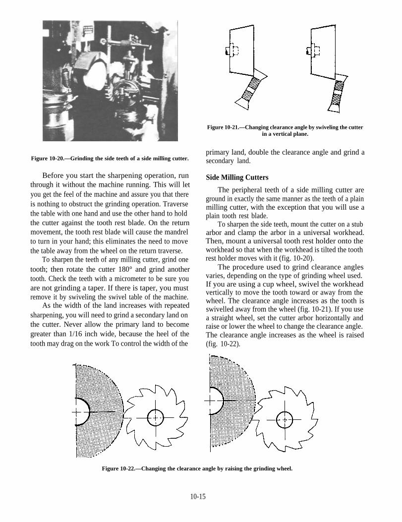
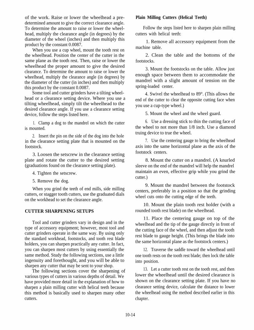
Figure 10-20.—Grinding the side teeth of a side milling cutter.
Before you start the sharpening operation, runthrough it without the machine running. This will letyou get the feel of the machine and assure you that thereis nothing to obstruct the grinding operation. Traversethe table with one hand and use the other hand to holdthe cutter against the tooth rest blade. On the returnmovement, the tooth rest blade will cause the mandrelto turn in your hand; this eliminates the need to movethe table away from the wheel on the return traverse.
To sharpen the teeth of any milling cutter, grind onetooth; then rotate the cutter 180° and grind anothertooth. Check the teeth with a micrometer to be sure youare not grinding a taper. If there is taper, you mustremove it by swiveling the swivel table of the machine.
As the width of the land increases with repeatedsharpening, you will need to grind a secondary land onthe cutter. Never allow the primary land to becomegreater than 1/16 inch wide, because the heel of thetooth may drag on the work To control the width of the
Figure 10-21.—Changing clearance angle by swiveling the cutterin a vertical plane.
primary land, double the clearance angle and grind asecondary land.
Side Milling Cutters
The peripheral teeth of a side milling cutter areground in exactly the same manner as the teeth of a plainmilling cutter, with the exception that you will use aplain tooth rest blade.
To sharpen the side teeth, mount the cutter on a stubarbor and clamp the arbor in a universal workhead.Then, mount a universal tooth rest holder onto theworkhead so that when the workhead is tilted the toothrest holder moves with it (fig. 10-20).
The procedure used to grind clearance anglesvaries, depending on the type of grinding wheel used.If you are using a cup wheel, swivel the workheadvertically to move the tooth toward or away from thewheel. The clearance angle increases as the tooth isswivelled away from the wheel (fig. 10-21). If you usea straight wheel, set the cutter arbor horizontally andraise or lower the wheel to change the clearance angle.The clearance angle increases as the wheel is raised(fig. 10-22).
Figure 10-22.—Changing the clearance angle by raising the grinding wheel.
10-15
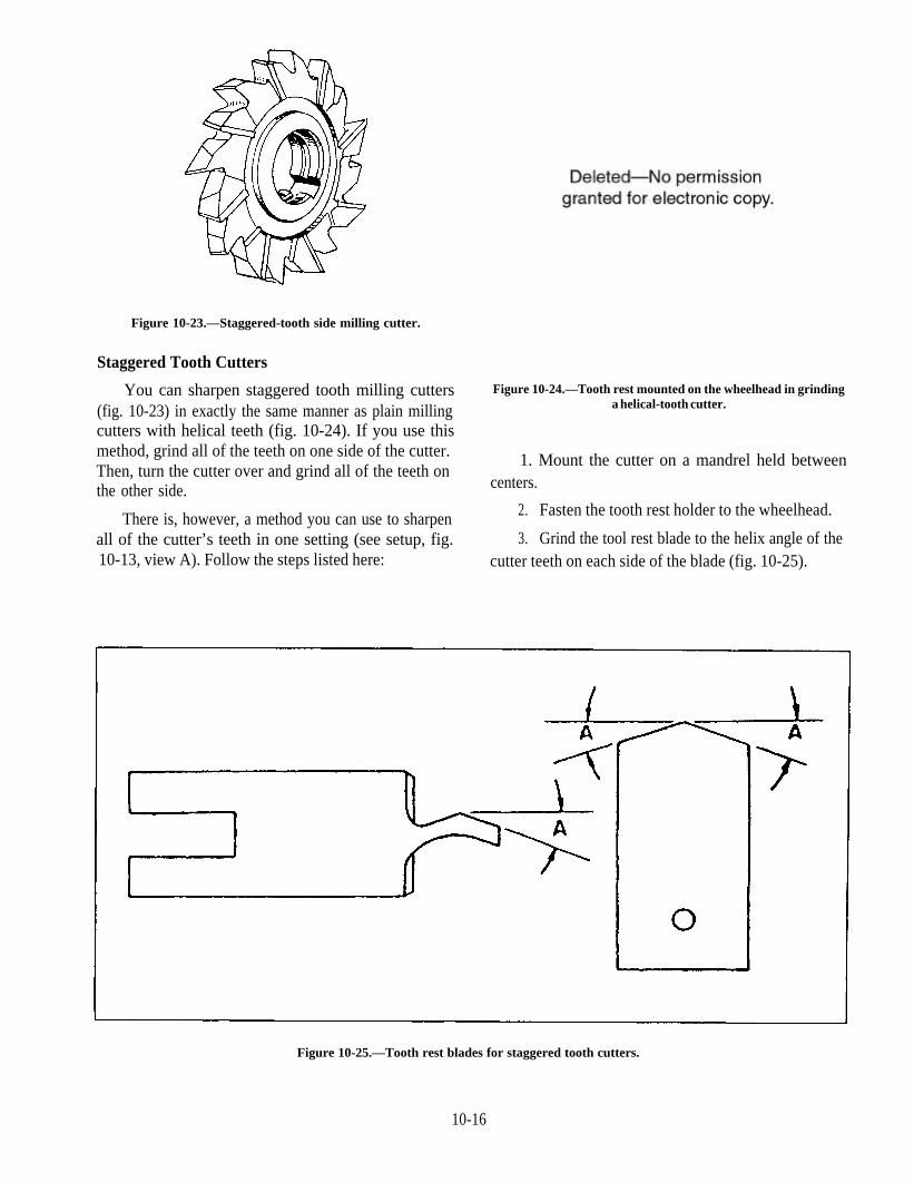
Figure 10-23.—Staggered-tooth side milling cutter.
Staggered Tooth Cutters
You can sharpen staggered tooth milling cutters(fig. 10-23) in exactly the same manner as plain millingcutters with helical teeth (fig. 10-24). If you use thismethod, grind all of the teeth on one side of the cutter.Then, turn the cutter over and grind all of the teeth onthe other side.
There is, however, a method you can use to sharpenall of the cutter’s teeth in one setting (see setup, fig.10-13, view A). Follow the steps listed here:
Figure 10-24.—Tooth rest mounted on the wheelhead in grindinga helical-tooth cutter.
1. Mount the cutter on a mandrel held betweencenters.
2. Fasten the tooth rest holder to the wheelhead.
3. Grind the tool rest blade to the helix angle of thecutter teeth on each side of the blade (fig. 10-25).
Figure 10-25.—Tooth rest blades for staggered tooth cutters.
10-16

Figure 10-26.—Resting the face of a tooth on its correspondingside of the tooth rest blade.
4. Position the high point of the tooth rest blade inthe center of the cutting face of the wheel.
5. Align the wheelhead shaft center line, thefootstock centers, and the high point of the tooth restblade in the same horizontal plane.
6. Raise or lower the wheelhead to give the desiredclearance angle.
7. Rest the face of a tooth on its corresponding sideof the tooth rest blade (fig. 10-26).
8. Move the cutting edge of the tooth across theface of the wheel. On the return cut, rest the next toothon the opposite angle of the tooth rest. Continuealternating teeth on each pass until you have sharpenedall the teeth.
Angular Cutters
To sharpen an angular cutter, mount the cutter on astub arbor and mount the arbor in a universal workhead.Then, swivel the workhead on its base to the angle ofthe cutter. If the cutter has helical teeth, mount the toothrest on the wheelhead. But, if the cutter has straightteeth, mount the tooth rest on the table or on theworkhead. To set the clearance angle for both types ofteeth, tilt the workhead the required number of degreestoward or away from the grinding wheel. Then, use acentering gauge to align the cutting edge of one toothparallel with the cutting face of the wheel. Take a lightcut to check your settings, and make fine adjustmentsuntil you get the desired clearance angle.
End Mills
You may salvage a damaged end mill by cutting offthe damaged portion with a cylindrical grindingattachment, as shown in figure 10-27. Use a coolant if
Figure 10-27.—Cutting off the damaged end of a helical end mill.
10-17

Figure 10-28.—Grinding the peripheral teeth of an end mill.
Figure 10-29.—Grinding the end teeth of a shell end mill.
possible to avoid removing the temper at the end of the the same procedure that you would use to sharpen acutter. Be sure to relieve the center of the end in the same plain milling cutter except for the method of mountingway as on the original cutter. the cutter. Mount the end mill in a universal workhead
Generally, it will not be necessary to sharpen the (fig. 10-28) instead of between centers. You mustperipheral teeth. However, if you must grind them, use remember that whenever you grind the peripheral teeth
10-18
of an end mill, you change the size (diameter) of thecutter. Therefore, you must show that the cutter size hasbeen changed. Either mark the new size on the cutter orgrind off the old size and leave the cutter unmarked.
Use the following steps to sharpen the end teeth:
1. Mount the end mill in a universal workhead.
2. Swivel the wheelhead to 89°.
3. Use a centering gauge to bring the cutting edgeof a tooth into the same horizontal plane as thewheelhead spindle axis. Place the gauge on top of thewheelhead and raise or lower the wheelhead enough toplace the blade of the gauge on the tooth’s cutting edge.This also will align the cutting edge with the centerlineof the wheel.
4. Lock the workhead spindle in place to preventthe cutter from moving.
5. Clamp the tooth rest blade onto the workhead sothat its supporting edge rests against the underside ofthe tooth to be ground.
6. Swivel the workhead downward to the desiredclearance angle and clamp it in position. At this point,make sure the tooth next to the one being ground willclear the wheel. If it does not, raise or lower thewheelhead until the tooth does clear the wheel.
7. Unclamp the workhead spindle and begingrinding the mill.
8. After you have ground all of the primary lands,tilt the workhead to the secondary clearance angle andgrind all the secondary lands.
On end mills with large diameter wheels, it is oftena good idea to back off the faces of the teeth toward thecenter of the cutter, similar to the teeth of a face mill.An angle of about 3° is enough, allowing a land of 3/16to 5/16 inch long.
You must use as much care when you grind thecomers of the teeth as when you grind the faces of theperipheral teeth. If not, the cutting edges will dullrapidly, and they will produce a poor finish. The comersof the teeth are usually chamfered 45° by swiveling theworkhead or table and are left 1/6 to 1/8 inch wide.
To sharpen the end teeth of a shell end mill (fig.10-29), mount the cutter on an arbor set in a taper shankmill bushing. Then, insert the bushing into the tapershank mill bushing sleeve held in the universalworkhead. To get the desired clearance angle, swivelthe workhead in the vertical plane and swivel it slightlyin the horizontal plane to grind the teeth low in the
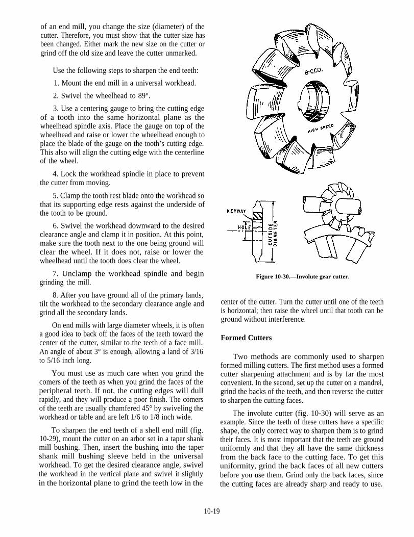
Figure 10-30.—Involute gear cutter.
center of the cutter. Turn the cutter until one of the teethis horizontal; then raise the wheel until that tooth can beground without interference.
Formed Cutters
Two methods are commonly used to sharpenformed milling cutters. The first method uses a formedcutter sharpening attachment and is by far the mostconvenient. In the second, set up the cutter on a mandrel,grind the backs of the teeth, and then reverse the cutterto sharpen the cutting faces.
The involute cutter (fig. 10-30) will serve as anexample. Since the teeth of these cutters have a specificshape, the only correct way to sharpen them is to grindtheir faces. It is most important that the teeth are grounduniformly and that they all have the same thicknessfrom the back face to the cutting face. To get thisuniformity, grind the back faces of all new cuttersbefore you use them. Grind only the back faces, sincethe cutting faces are already sharp and ready to use.
10-19
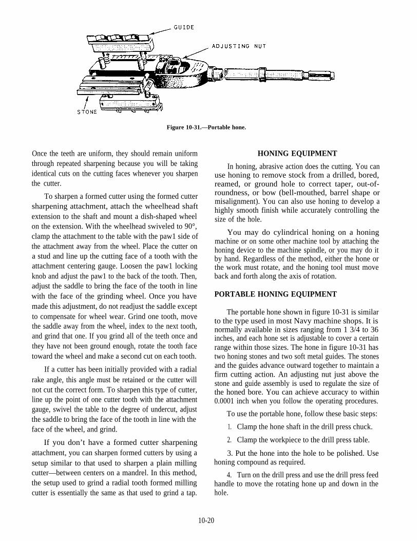
Figure 10-31.—Portable hone.
Once the teeth are uniform, they should remain uniformthrough repeated sharpening because you will be takingidentical cuts on the cutting faces whenever you sharpenthe cutter.
To sharpen a formed cutter using the formed cuttersharpening attachment, attach the wheelhead shaftextension to the shaft and mount a dish-shaped wheelon the extension. With the wheelhead swiveled to 90°,clamp the attachment to the table with the paw1 side ofthe attachment away from the wheel. Place the cutter ona stud and line up the cutting face of a tooth with theattachment centering gauge. Loosen the paw1 lockingknob and adjust the paw1 to the back of the tooth. Then,adjust the saddle to bring the face of the tooth in linewith the face of the grinding wheel. Once you havemade this adjustment, do not readjust the saddle exceptto compensate for wheel wear. Grind one tooth, movethe saddle away from the wheel, index to the next tooth,and grind that one. If you grind all of the teeth once andthey have not been ground enough, rotate the tooth facetoward the wheel and make a second cut on each tooth.
If a cutter has been initially provided with a radialrake angle, this angle must be retained or the cutter willnot cut the correct form. To sharpen this type of cutter,line up the point of one cutter tooth with the attachmentgauge, swivel the table to the degree of undercut, adjustthe saddle to bring the face of the tooth in line with theface of the wheel, and grind.
If you don’t have a formed cutter sharpeningattachment, you can sharpen formed cutters by using asetup similar to that used to sharpen a plain millingcutter—between centers on a mandrel. In this method,the setup used to grind a radial tooth formed millingcutter is essentially the same as that used to grind a tap.
HONING EQUIPMENT
In honing, abrasive action does the cutting. You canuse honing to remove stock from a drilled, bored,reamed, or ground hole to correct taper, out-of-roundness, or bow (bell-mouthed, barrel shape ormisalignment). You can also use honing to develop ahighly smooth finish while accurately controlling thesize of the hole.
You may do cylindrical honing on a honingmachine or on some other machine tool by attaching thehoning device to the machine spindle, or you may do itby hand. Regardless of the method, either the hone orthe work must rotate, and the honing tool must moveback and forth along the axis of rotation.
PORTABLE HONING EQUIPMENT
The portable hone shown in figure 10-31 is similarto the type used in most Navy machine shops. It isnormally available in sizes ranging from 1 3/4 to 36inches, and each hone set is adjustable to cover a certainrange within those sizes. The hone in figure 10-31 hastwo honing stones and two soft metal guides. The stonesand the guides advance outward together to maintain afirm cutting action. An adjusting nut just above thestone and guide assembly is used to regulate the size ofthe honed bore. You can achieve accuracy to within0.0001 inch when you follow the operating procedures.
To use the portable hone, follow these basic steps:
1. Clamp the hone shaft in the drill press chuck.
2. Clamp the workpiece to the drill press table.
3. Put the hone into the hole to be polished. Usehoning compound as required.
4. Turn on the drill press and use the drill press feedhandle to move the rotating hone up and down in thehole.
10-20

When you use a lathe (vertical or horizontal) tohone, you can mount the work in a chuck or on afaceplate and rotate it. In this arrangement, you will holdthe honing tool in the tailstock with a chuck and use thetailstock spindle to move it back and forth in theworkpiece bore.
When you use a milling machine or a horizontalboring mill, mount the workpiece on the table and thehoning tool in the spindle. Move the machine table topass the hone back and forth in the workpiece bore.
You also can use a hand-held power drill to rotatethe hone in the workpiece. Move the rotating hone inand out of the hole by hand.
Each of these methods requires that the hone beallowed to self-align with the workpiece bore. To helpthis process, place one or two universals between thehone shaft and the device or spindle that will hold ordrive the hone. Hone manufacturers can usually furnishthese universals and shaft extensions.
When you hone large bores, use a device thatattaches to the hone and lends support to the stones andguides to ensure a rigid setup.
STATIONARY HONING MACHINE
Most large machine shops have a stationary honingmachine such as the one shown in figure 10-32. Thesemachines are usually self-contained hones with abuilt-in honing oil pump and reservoir, a workholdingdevice, and a spindle to rotate and stroke the honingstones. They usually have standard controls to adjust therpm, the rate of stroke, and the pressure feeding thestones to the desired size. Most models have a zerosetting dial indicator that lets you know when thedesired bore size is reached. Follow your machinemanufacturer’s operating manual.
STONE SELECTION
The honing stone is made somewhat like a grindingwheel, with grit, a bond, and air voids. The grit is thecutting edge of the tool. It must be tough enough towithstand the pressure needed to make it penetrate thesurface, but not so tough that it cannot fracture andsharpen itself. The bond must be strong enough to holdthe grit, but not so strong that it rubs on the bore andinterferes with the cutting action of the grit. Air voidsin the structure of the stone help the coolant or honingoil clear chips and dissipate heat.
Honing stones have either aluminum oxide grit forferrous metals or silicon carbide grit for nonferrous
Figure 10-32.—Stationary honing machine.
metals and glass. Grit sizes range from 150 to 400. Ifyou need to remove a large amount of metal, use acoarse grit stone such as a 150-grit to bring the base towithin 0.0002 to 0.001 inch of the finish size. Then, usea finer grit stone to get a smooth finish. The honemanufacturer will recommend stones needed forspecific jobs.
HONING HINTS
Honing does not change the axial location of a hole.The center line of the honing tool aligns itself with thecenter line of the bore. Either the tool or the part floatsto ensure that the tool and the base align. Floating allowsthe tool to exert equal pressure on all sides of the bore.
As the honing tool is stroked through the bore, thepressure of the grit is greatest at the tight spots. There-fore, the hone takes out all taper and out-of-roundnessbefore it removes any stock from the larger section ofthe bore. It also takes out any bow. Since the honingstones are rigid throughout their length, they cannotfollow a bow—they bridge the low spots and cut deeperon the high spots, tending to straighten out a bow.
10-21

After you have honed out the inaccuracies, youmust abrade every section of the bore equally. To besure this happens, maintain both the rotating andreciprocating motions so that every part of the bore iscovered before any grit repeats its path of travel.
round, and straight bore. After heat-treating the work-piece, finish hone to correct any minor distortion and toproduce the desired finish.
Honing produces a crosshatch finish. The depth of
If a bore will require honing to correct taper orout-of-roundness, leave about twice as much stock forhoning as there is error in the bore. It is sometimespractical and economical to perform two honingoperations: (1) rough honing to remove stock and (2)finish honing to develop the desired finish. We saidearlier that you should leave from 0.0002 to 0.001 inchfor finish honing.
If a machined bore must be heat-treated, rough honeit before heat treating to produce an accurately sized,
cut depends on the abrasive, speed, pressure, andcoolant or honing oil used. To produce a finer finish,you can do one or all of the following:
1. Use a finer grit stone.
2. Increase the rotating speed.
3. Decrease the stroking speed.
4. Decrease the feed pressure
5. Increase the coolant flow.
10-22