Embed Size (px)
Citation preview
Precision Fiber Laser Cutting of Thin Metals;
Fundamentals and Capability
Geoff Shannon
Laser Technology Manager
AGENDA
• Introduction
• Benefits of laser cutting• Elements of a laser cutting system• Key Process Parameters• Materials • Geometry & Applications• System examples
2
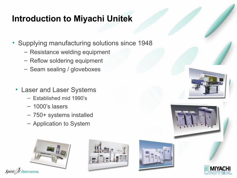
Introduction to Miyachi Unitek
• Supplying manufacturing solutions since 1948– Resistance welding equipment– Reflow soldering equipment– Seam sealing / gloveboxes
• Laser and Laser Systems– Established mid 1990’s
– 1000’s lasers– 750+ systems installed
– Application to System
4
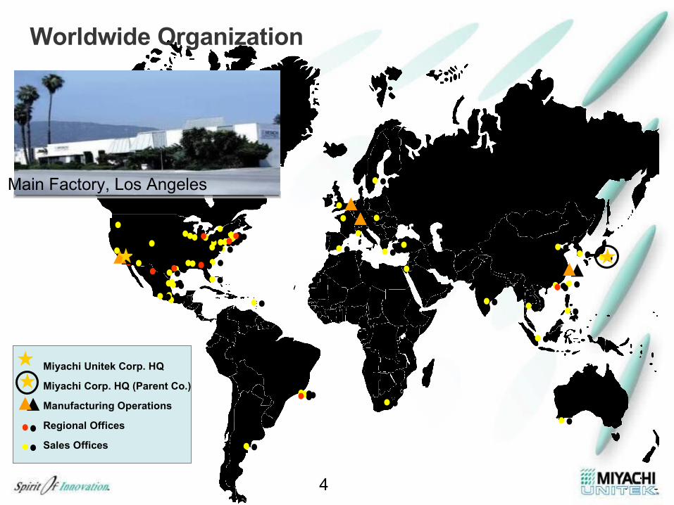
Worldwide Organization
Miyachi Unitek Corp. HQ
Miyachi Corp. HQ (Parent Co.)
Manufacturing Operations
Regional Offices
Sales Offices
Main Factory, Los Angeles
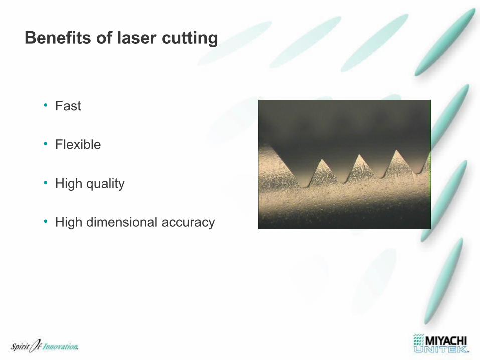
Benefits of laser cutting
• Fast
• Flexible
• High quality
• High dimensional accuracy
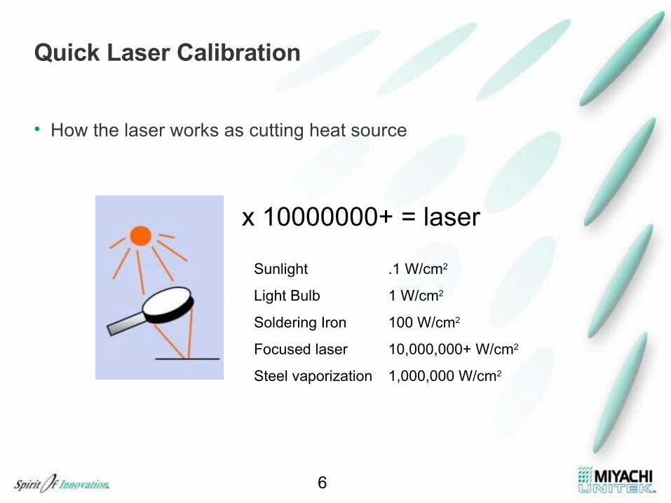
Quick Laser Calibration
• How the laser works as cutting heat source
6
x 10000000+ = laser
Sunlight .1 W/cm2
Light Bulb 1 W/cm2
Soldering Iron 100 W/cm2
Focused laser 10,000,000+ W/cm2
Steel vaporization 1,000,000 W/cm2
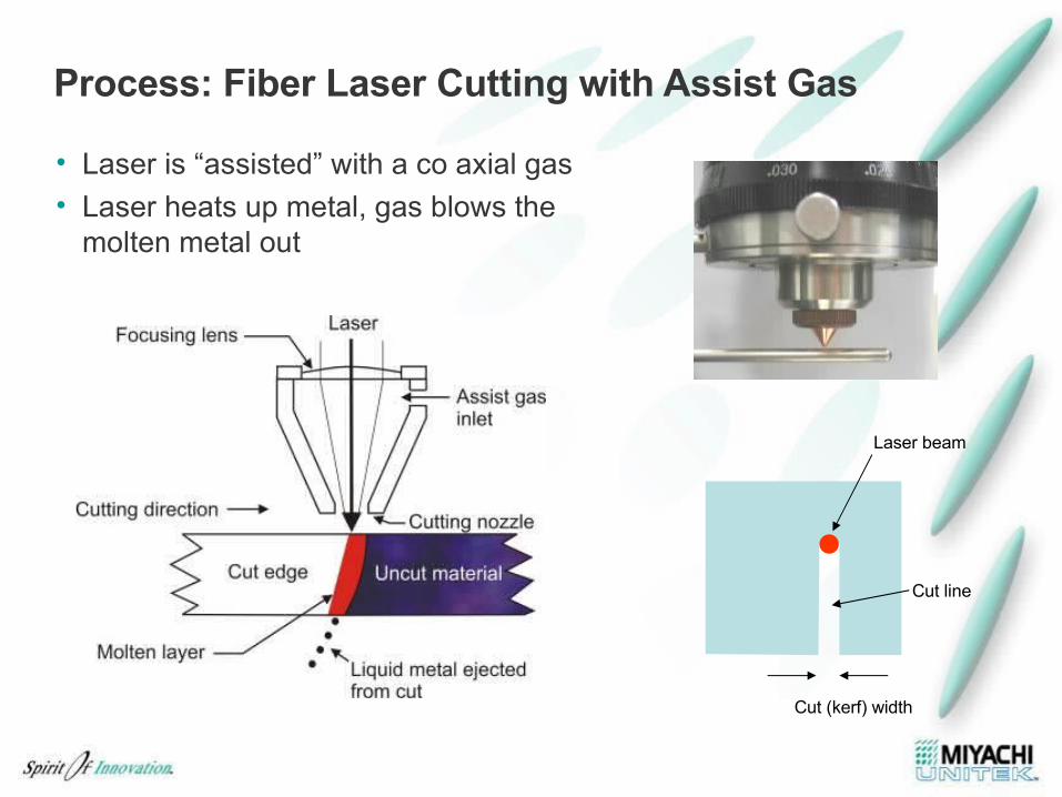
Process: Fiber Laser Cutting with Assist Gas
• Laser is “assisted” with a co axial gas• Laser heats up metal, gas blows the
molten metal out
Laser beam
Cut line
Cut (kerf) width
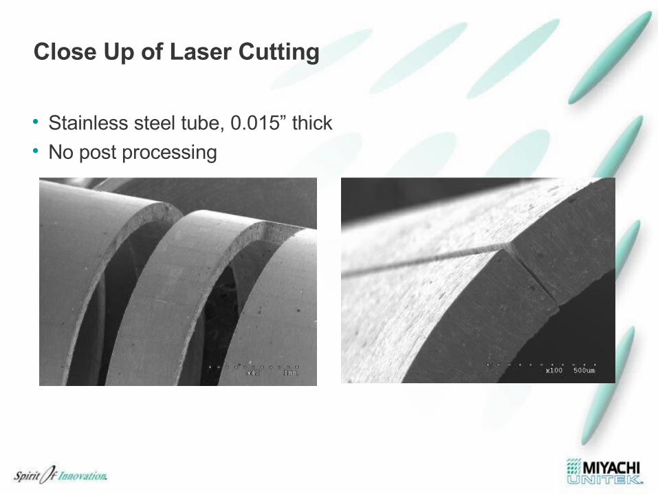
Close Up of Laser Cutting
• Stainless steel tube, 0.015” thick• No post processing
9
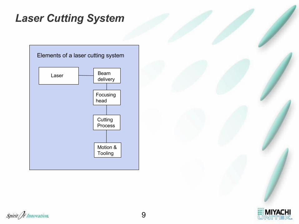
Laser Cutting System
Laser
Elements of a laser cutting system
Beam delivery
Focusing head
CuttingProcess
Motion &Tooling
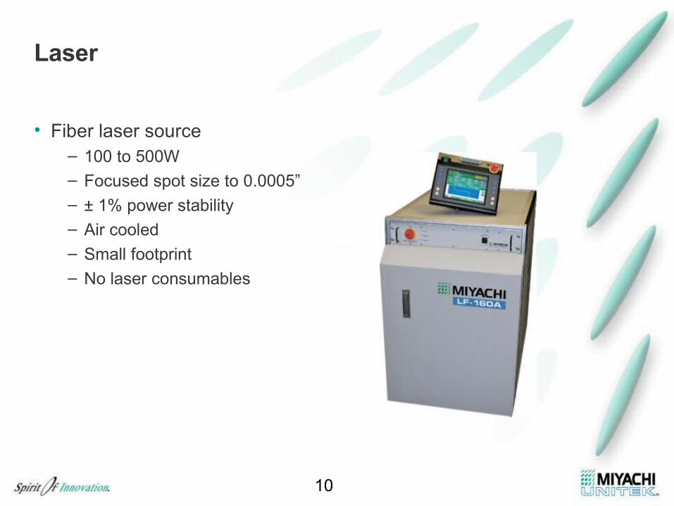
Laser
• Fiber laser source– 100 to 500W– Focused spot size to 0.0005”– ± 1% power stability– Air cooled
– Small footprint
– No laser consumables
10
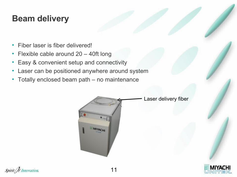
Beam delivery
• Fiber laser is fiber delivered!
• Flexible cable around 20 – 40ft long • Easy & convenient setup and connectivity • Laser can be positioned anywhere around system
• Totally enclosed beam path – no maintenance
11
Laser delivery fiber

Focusing Head
• Determines laser focus spot size
• Directs laser and assist gas through gas nozzle
• Camera option to view process
12
Laser
Camera
Dichroicmirror
Focus lens
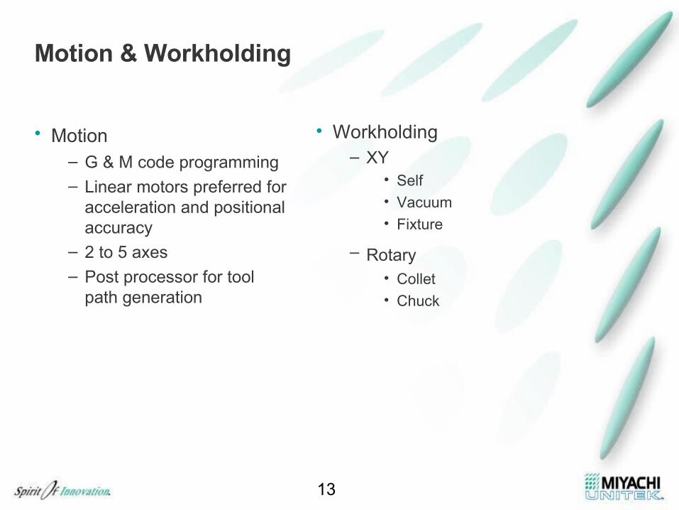
Motion & Workholding
• Motion – G & M code programming– Linear motors preferred for
acceleration and positional accuracy
– 2 to 5 axes
– Post processor for tool path generation
• Workholding– XY
• Self• Vacuum• Fixture
– Rotary • Collet • Chuck
13
Key Process Parameters
• Laser parameters– Power, pulse width, frequency
• Optical parameters– Focus spot size, depth of focus
• Gas assist– Gas type, pressure, nozzle type
• Speed– Maximize!
14
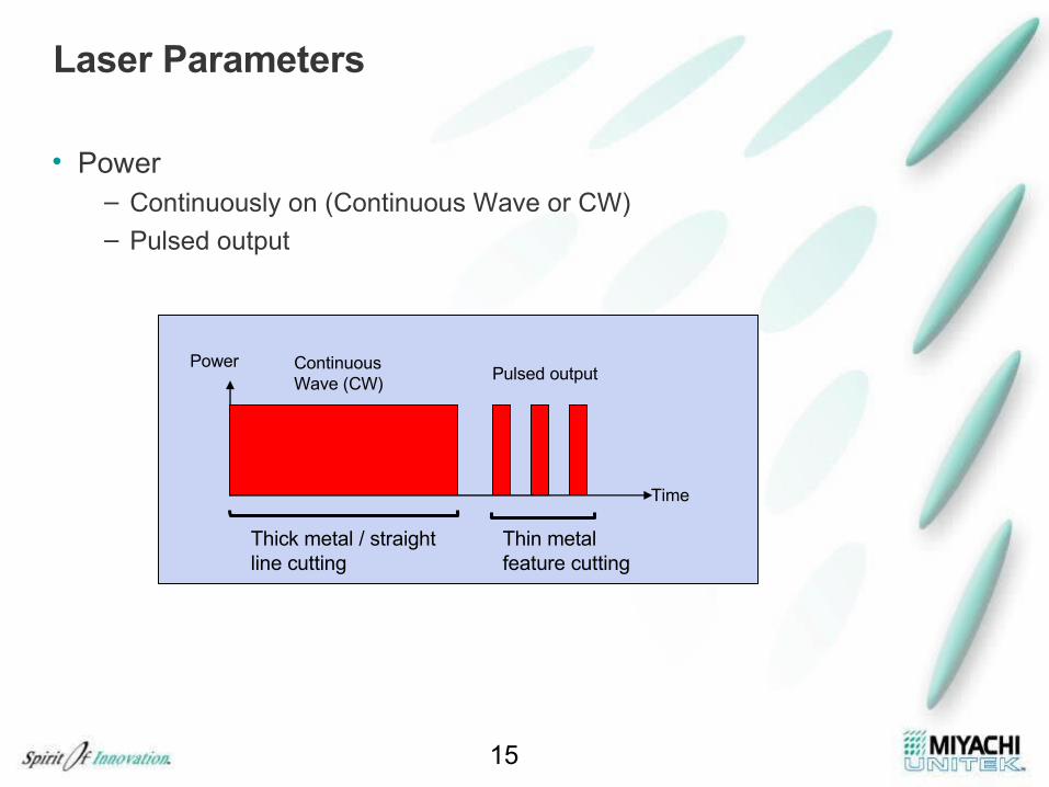
Laser Parameters
• Power– Continuously on (Continuous Wave or CW)– Pulsed output
15
Power
Time
Pulsed outputContinuous Wave (CW)
Thick metal / straightline cutting
Thin metal feature cutting
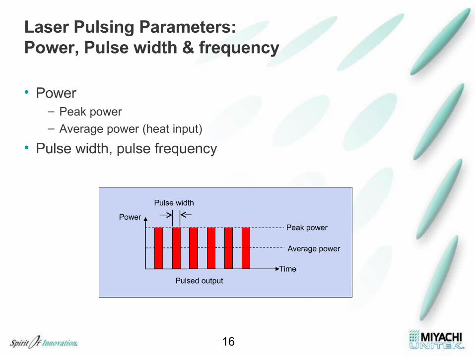
Laser Pulsing Parameters: Power, Pulse width & frequency
• Power– Peak power– Average power (heat input)
• Pulse width, pulse frequency
16
Power
Time
Pulsed output
Peak power
Average power
Pulse width
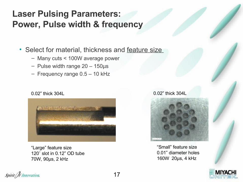
Laser Pulsing Parameters: Power, Pulse width & frequency
• Select for material, thickness and feature size – Many cuts < 100W average power– Pulse width range 20 – 150µs– Frequency range 0.5 – 10 kHz
17
“Large” feature size120˚ slot in 0.12” OD tube 70W, 90µs, 2 kHz
“Small” feature size0.01” diameter holes 160W 20µs, 4 kHz
0.02” thick 304L 0.02” thick 304L
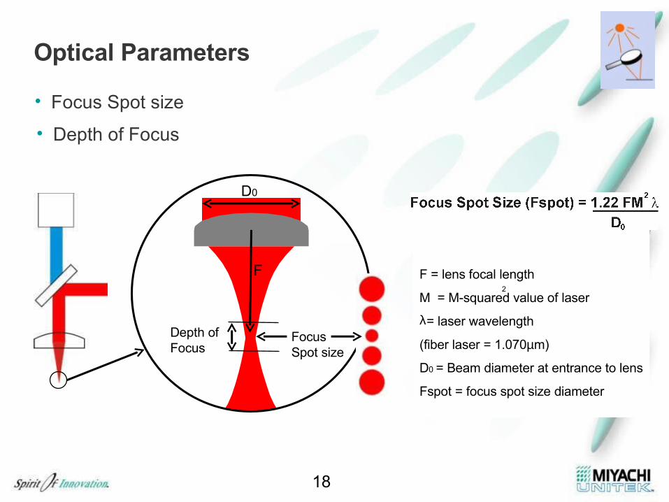
Optical Parameters
• Focus Spot size
18
FocusSpot size
Depth of Focus
D0
F F = lens focal length
M = M-squared value of laser
λ= laser wavelength
(fiber laser = 1.070µm)
D0 = Beam diameter at entrance to lens
Fspot = focus spot size diameter
2
• Depth of Focus
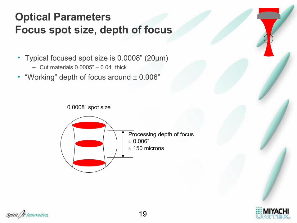
Optical ParametersFocus spot size, depth of focus
• Typical focused spot size is 0.0008” (20µm)– Cut materials 0.0005” – 0.04” thick
• “Working” depth of focus around ± 0.006”
19
Processing depth of focus± 0.006”± 150 microns
0.0008” spot size
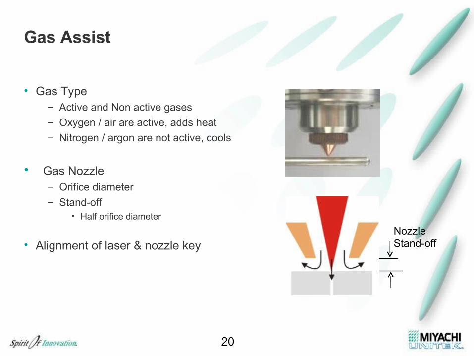
Gas Assist
• Gas Type– Active and Non active gases– Oxygen / air are active, adds heat– Nitrogen / argon are not active, cools
• Gas Nozzle– Orifice diameter– Stand-off
• Half orifice diameter
• Alignment of laser & nozzle key
20
NozzleStand-off
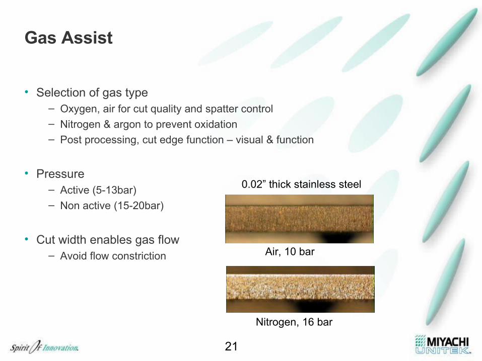
Gas Assist
• Selection of gas type – Oxygen, air for cut quality and spatter control– Nitrogen & argon to prevent oxidation– Post processing, cut edge function – visual & function
• Pressure– Active (5-13bar)– Non active (15-20bar)
• Cut width enables gas flow– Avoid flow constriction
21
0.02” thick stainless steel
Air, 10 bar
Nitrogen, 16 bar
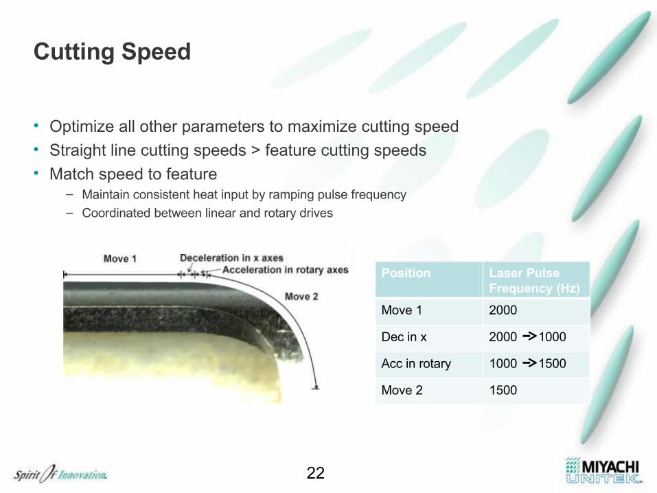
Cutting Speed
• Optimize all other parameters to maximize cutting speed
• Straight line cutting speeds > feature cutting speeds• Match speed to feature
– Maintain consistent heat input by ramping pulse frequency – Coordinated between linear and rotary drives
22
Position Laser Pulse Frequency (Hz)
Move 1 2000
Dec in x 2000 1000
Acc in rotary 1000 1500
Move 2 1500
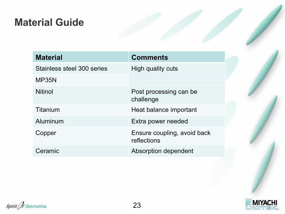
Material Guide
23
Material Comments
Stainless steel 300 series High quality cuts
MP35N
Nitinol Post processing can be challenge
Titanium Heat balance important
Aluminum Extra power needed
Copper Ensure coupling, avoid back reflections
Ceramic Absorption dependent
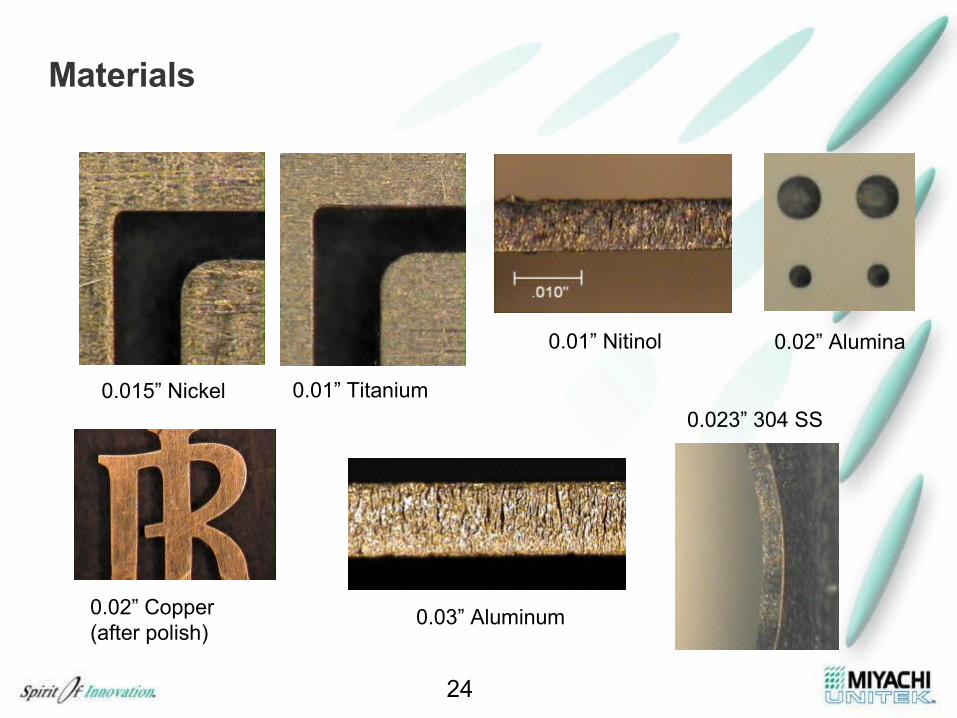
Materials
24
0.015” Nickel 0.01” Titanium
0.01” Nitinol 0.02” Alumina
0.023” 304 SS
0.02” Copper(after polish)
0.03” Aluminum
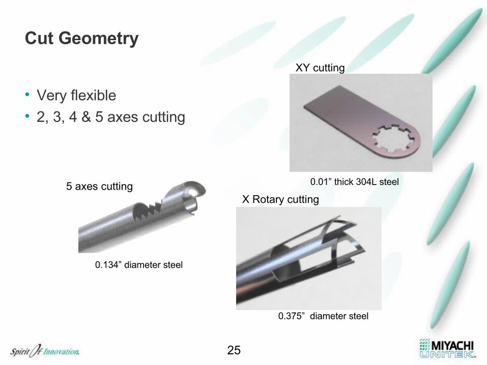
Cut Geometry
• Very flexible
• 2, 3, 4 & 5 axes cutting
25
0.01” thick 304L steel
0.375” diameter steel
0.134” diameter steel
XY cutting
X Rotary cutting5 axes cutting
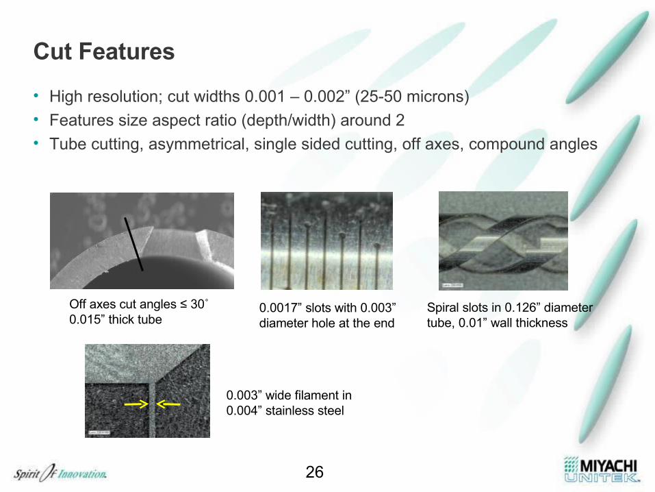
Cut Features
• High resolution; cut widths 0.001 – 0.002” (25-50 microns)
• Features size aspect ratio (depth/width) around 2• Tube cutting, asymmetrical, single sided cutting, off axes, compound angles
26
Off axes cut angles ≤ 30˚0.015” thick tube
0.0017” slots with 0.003” diameter hole at the end
Spiral slots in 0.126” diametertube, 0.01” wall thickness
0.003” wide filament in0.004” stainless steel
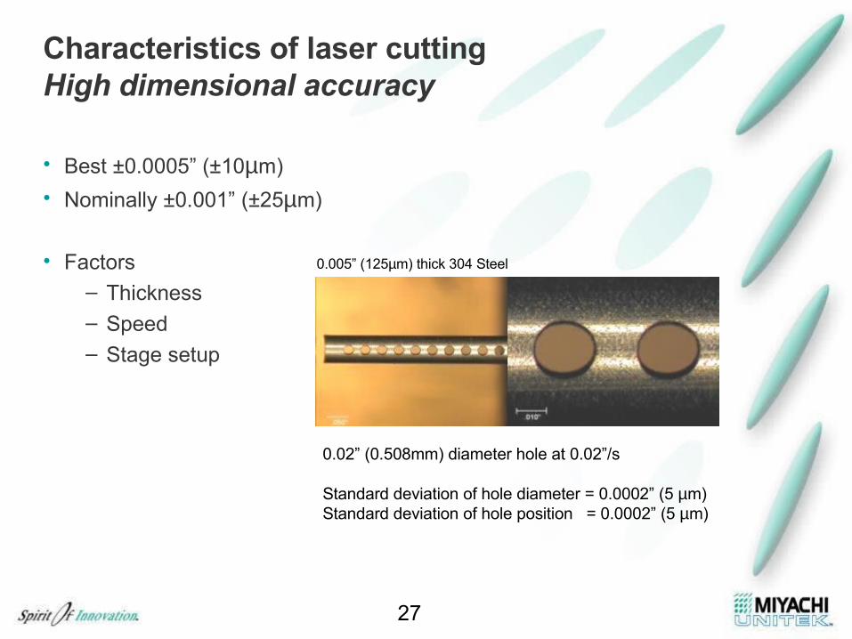
Characteristics of laser cutting High dimensional accuracy
• Best ±0.0005” (±10µm)
• Nominally ±0.001” (±25µm)
• Factors– Thickness
– Speed
– Stage setup
27
0.005” (125µm) thick 304 Steel
0.02” (0.508mm) diameter hole at 0.02”/s
Standard deviation of hole diameter = 0.0002” (5 µm)Standard deviation of hole position = 0.0002” (5 µm)
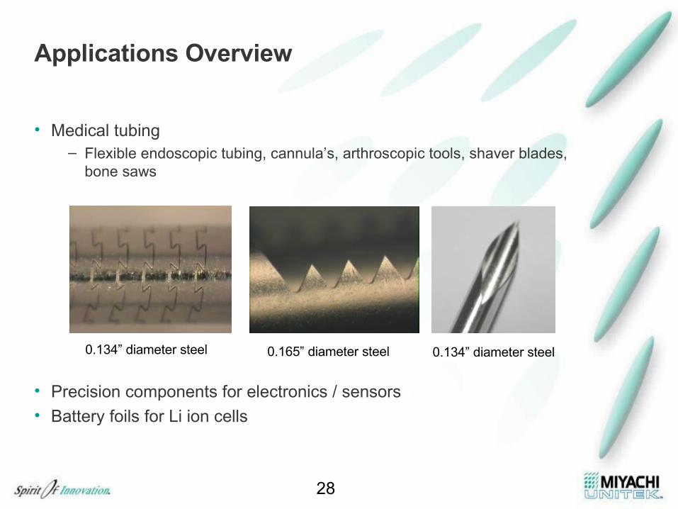
Applications Overview
• Medical tubing– Flexible endoscopic tubing, cannula’s, arthroscopic tools, shaver blades,
bone saws
• Precision components for electronics / sensors
• Battery foils for Li ion cells
28
0.134” diameter steel 0.165” diameter steel 0.134” diameter steel
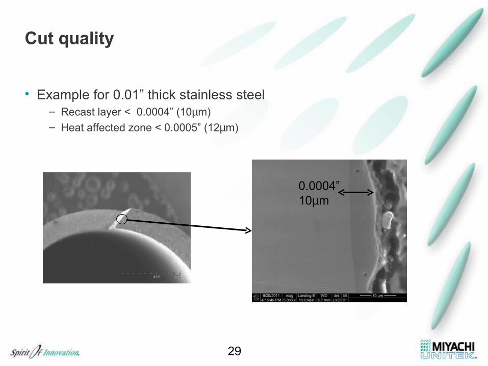
Cut quality
• Example for 0.01” thick stainless steel– Recast layer < 0.0004” (10µm)– Heat affected zone < 0.0005” (12µm)
29
0.0004”10µm
Cutting System Platforms
• 2,3 axes XY cutting
• 2,3,4 axes tube cutting
• 5 Axes cutting
30
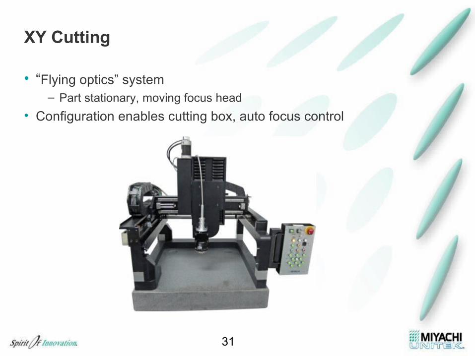
XY Cutting
• “Flying optics” system – Part stationary, moving focus head
• Configuration enables cutting box, auto focus control
31
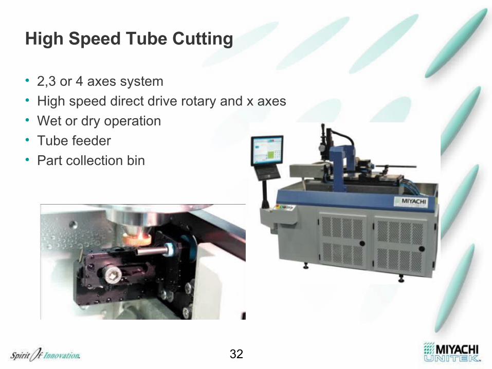
High Speed Tube Cutting
32
• 2,3 or 4 axes system• High speed direct drive rotary and x axes• Wet or dry operation• Tube feeder• Part collection bin
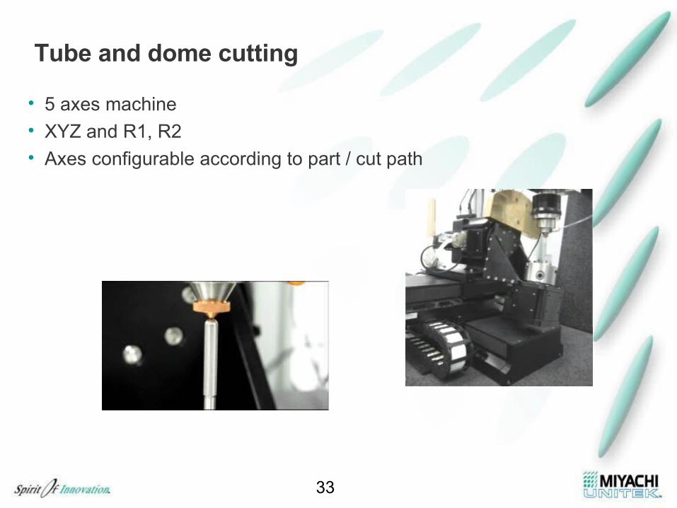
Tube and dome cutting
33
• 5 axes machine• XYZ and R1, R2• Axes configurable according to part / cut path
Summary
• The fiber laser is a competitive tool for high speed precision cutting
• Excellent cut quality in many metals• Unique cutting capability• Fully integrated cutting systems in 2,3,4 & 5 axes
34