Embed Size (px)
Citation preview
2015 WJTA-IMCA Conference and Expo November 2-4 ズ New Orleans, Louisiana
Paper
ABRASIVE WATERJET MACHINING EFFECTS ON KERF QUALITY
IN THIN FIBER METAL LAMINATE
M. Ramulu, R. Pahuja, M. Hashish*, V. Isvilonanda, University of Washington,
Seattle, Washington, U.S.A.
*Flow International Corporation, Kent, Washington, U.S.A.
ABSTRACT
High temperature Fiber Metal Laminate – Titanium/Graphite (Ti/Gr) is an advanced material system, developed to meet the high temperature requirements in aerospace applications. High specific strength and stiffness of composite core along with its protection from aggressive environment by tough titanium alloy sheets, qualify FMLs for a promising alternative material where metallic and composites overcome each other’s limitations. However, industrial employability of this three phase system is often limited by the machining challenges posed by the difference in material removal mechanisms of Titanium alloy, PIXA thermoplastic polyimide resin and graphite fibers. An experimental investigation was conducted to evaluate the machinability of 1 mm thick Ti/Gr laminate sheets through Abrasive Waterjet (AWJ) machining process in terms of kerf characteristics and material removal rate. The parametric influence of AWJ operating variables on machining performance was studied by systematically measuring operating variables (traverse speed and Abrasive flow rate) using fully crossed Design of experiment (DOE) scheme, and statistically analyzing using ANOVA (Analysis of variance) technique. Empirical models were developed to quantify these effects and predict the influence of process parameters on material removal rate, kerf taper, entry damage width and overcut in straight cutting of Ti/Gr sheets.
Organized and Sponsored by WJTA®-IMCA ®
1. INTRODUC TION Hybrid composite laminates, also known as Fiber Metal Laminates (FML) is a group of engineered materials consisting of polymer matrix composites (PMC) plies interspersed with metal foils. The capability to withstand aggressive environment, high temperature; to resist oxidation and moisture ingress while maintaining structural integrity are few reasons why FMLs are known as new age engineered materials. This hybrid material system was first developed by Delft Research Group as ARALL ® (Aramid Fiber Aluminum Laminate) followed by GLARE® (Glass Fiber Aluminum Reinforced Epoxy). However development of Titanium Graphite laminate (TiGr) by The Boeing Research Group along with NASA Langley Research Center has outperformed both the previously developed material systems in terms of fatigue strength, tensile strength and Inter-Laminar Shear Strength (ILSS). Bourlegat et al. [1] reported 95% improvement of tensile strength and 37% improvement in ILSS of TiGr when compared to GLARE®. TiGr is composed of alternate layers of graphite reinforced thermoplastic composite (PIXA-M) and titanium sheets. It is widely characterized as a futuristic material and finding employability in aerospace applications to address the future needs where aircrafts could high skin temperatures (177 °C) at supersonic speeds >3 mach. The directional properties of carbon composite (better fatigue characteristics, high stiffness-to-weight, and strength-to-weight ratio) with added benefits of Titanium alloy sheets (high tensile and flexural strength, high stiffness) coupled with properties rendered by hybrid nature of the system such as protection of composite core from heat and moisture, better distribution of point load and enhanced compression after impact (CAI) strength [2-5] by titanium sheets. Although, TiGr laminates are generally molded/autoclaved to a near net shape, secondary machining is often required. Machining of composites alone poses a great challenge, which becomes even worse in a three phase material system – hybrid composites, where the non-homogeneity and anisotropy of composites together with the difference in the removal mechanism for all the three different phases aggravate machining problem. Machining of composite laminates using conventional processes is often limited by excessive tool wear and thermal distortion, fiber pull out, matrix cratering, delamination, fraying, machining dust and burr formation from metal foils [6-14]. Several investigators have reported that up to 60% of the rejected composite parts come from secondary machining defects [10-14], foregrounding the need and importance of more precise and non-traditional methods in composite machining. Several non-traditional methods have been studied for the machining of composites. Ultrasonic machining is widely employed for brittle matrix composites (ceramic composites). Electrical discharge machining (EDM) has been employed to machine electrically conductive composite materials. However, objectionable surface integrity, high delamination due to arching and low MRR account for its inaptness in machining fiber metal laminates. Laser cutting is well suited for contour trimming of carbon fiber reinforced plastics because of point-sized geometry and multidirectional cutting ability. However, uneven kerf width and decrease in static strength of components due to thermal cracking and large HAZ restricts its use. Abrasive Waterjet machining is a widely used unconventional alternative because of properties such as no thermal damage to the workpiece, high cutting speed, wide working range and environmental friendly. Several FEM, analytical and experimental models have been developed to predict the effect of process parameters on the performance of machining ceramics and composites. However, the AWJ machining of laminates is seldom studied due to the complexity of the cutting process. Paul et al.
[15] studied the material removal process and quantified the effect of different parameters on GLARE®. In this study, the machinability of TiGr is investigated and determined in terms of Material Removal Rate (MRR), kerf characteristics – overcut, damage width and taper as performance parameters of straight profile thin TiGr sheets. AWJ process variables are evaluated and optimized for high machinability. ANOVA is applied to statistically quantify the response of these variables and develop regression models to establish a nexus between these variables and machining response. 2. EXPERIMENT 2.1 Experimental Setup and Conditions TiGr specimens were obtained from The Boeing Company in the form of ににぱ 抜 にぱ 抜 な mm, each composed of 8 plies with layers of graphite reinforced polymer matrix composite (PIXA-M) and 117 µm thick titanium alloy foils (Ti-15V-3Cr-3Sn-3Al) stacked together using autoclave consolidation process. The ply stacking sequence is Ti,90°,Ti,0°,0°,Ti,90°,Ti as depicted in Figure 1(c). Reinforced fibers in the composite were IM-7 intermediate modulus carbon fibers and the matrix used was LARC-IAX polymer. The mechanical properties of Titanium, fiber, and matrix material are depicted in Table 1. A Flow Water Jet Pro model WJP1313 (CNC controlled) AWJ machine equipped with vacuum assist was used. Table 2. provides the description of experimental conditions and constant parameters used in this study. 2.2 Design and Methodology The experiment was designed according to Full Factorial Scheme of Design of Experiments (DOE). The design matrix is depicted in Table 4. Three levels of traverse speed and abrasive flow rate were selected, as mentioned in Table 3, on the basis of previous investigations [4, 10, 16]. Nine straight cuts of approximately 22 mm long were machined at constant jet pressure setting (275.8 MPa) with 8 mm spacing between each cut, as depicted in Figure 1(b). Analysis of Variance (ANOVA) was performed to study the effect of individual process parameters and their interaction on machining responses. The cutting process is depicted in Figure 1 (a) and the responses studied in the process are defined as follows.
Overcut is defined as the variation of predefined and actual dimension of cut for both entry and exit side and was calculated according to Equation (1). Overcut dimension is important in order to assign dimensional compensation to the NC program and achieve a tighter geometric tolerances. 頚懸結堅潔憲建 噺 岫激頂通痛 伐 穴痛墜墜鎮岻 にエ (1)
Kerf Taper is defined as the difference between entry and exit kerf width averaged over thickness over the workpiece. Kerf width was measured by optical microscopy. 計結堅血 劇欠喧結堅 噺 岫穴勅津痛追槻 伐 穴勅掴沈痛岻 に建エ (2)
Damage width is the width of discolored region on Titanium alloy face sheet around the cut, observed under optical microscope. 経欠兼欠訣結 拳件穴建月 噺 岫経 伐 穴岻 にエ 噺 岫継券建堅検 頚懸結堅潔憲建 伐 継捲件建 頚懸結堅潔憲建岻 建エ (3)
D is the dimension of discolored region across the cut feature and d is the dimension of feature machined. The reason for reporting only entry damage width is the poor visibility of exit damage under optical microscopy due to its negligible size. Analysis of Variance (ANOVA) was performed using Design-Expert v7.1.5 software with 95% confidence level in order to analyze and determine the effect of traverse speed and AFR on the machining response. 3. RESULTS AND DISCUSSION 3.1 Kerf Surface Observations As shown in Figure 2, rounded edge along the entry side of the jet was identified as the Initial damage region, followed by Smooth cutting and Rough cutting region as previously observed by Ramulu et al. [10, 14, 17]. Higher visible damage and distortion was observed in the middle composite plies. No delamination was observed in the chosen domain of parameters. SEM inspection was carried on to observe the mechanism of material removal for titanium, graphite fiber and thermoplastic matrix as different phases. Specimen machined with lowest traverse speed (60 mm/min) and highest abrasive flow rate (9.78 g/s) showed wear tracks and signs of shear deformation on titanium ply (Figure 3a) concluding that Titanium was cut by ductile shearing, abrasive plowing, and scratching action, as observed by Seo et al. [18]. Further within PIXA-M composite, LARC-IAX matrix material and IM-7carbon fiber also subjected to different material removal mechanisms. The matrix material was removed by shearing and plastic deformation while fibers were cut by micro chipping, brittle fracture, and bending failure. The bending and chipping can be easily observed in Figure 3(b), depicting PIXA-M ply machined at 720 mm/min traverse speed and 3.35 g/s AFR. Thickness of the specimen was small enough that a smooth cutting region was extended throughout the depth. In some location, an abrasive particle plowed through the material, fractured, and embedded to the bottom of the track was detected and as shown in Figure 3(c). The surface characteristics for cut surfaces were investigated. It was observed that using high traverse speed and low AFR resulted in more topologically irregular surface. However, entry damage on the top titanium ply was smaller. Cleaner and smoother cut surface was obtained at low traverse speed and high AFR. At this condition, shallower grooves and smaller titanium burrs were observed. Within the range of experimental conditions, all plies remained intact and no delamination was observed. Average surface roughness for the best and worst surface condition is
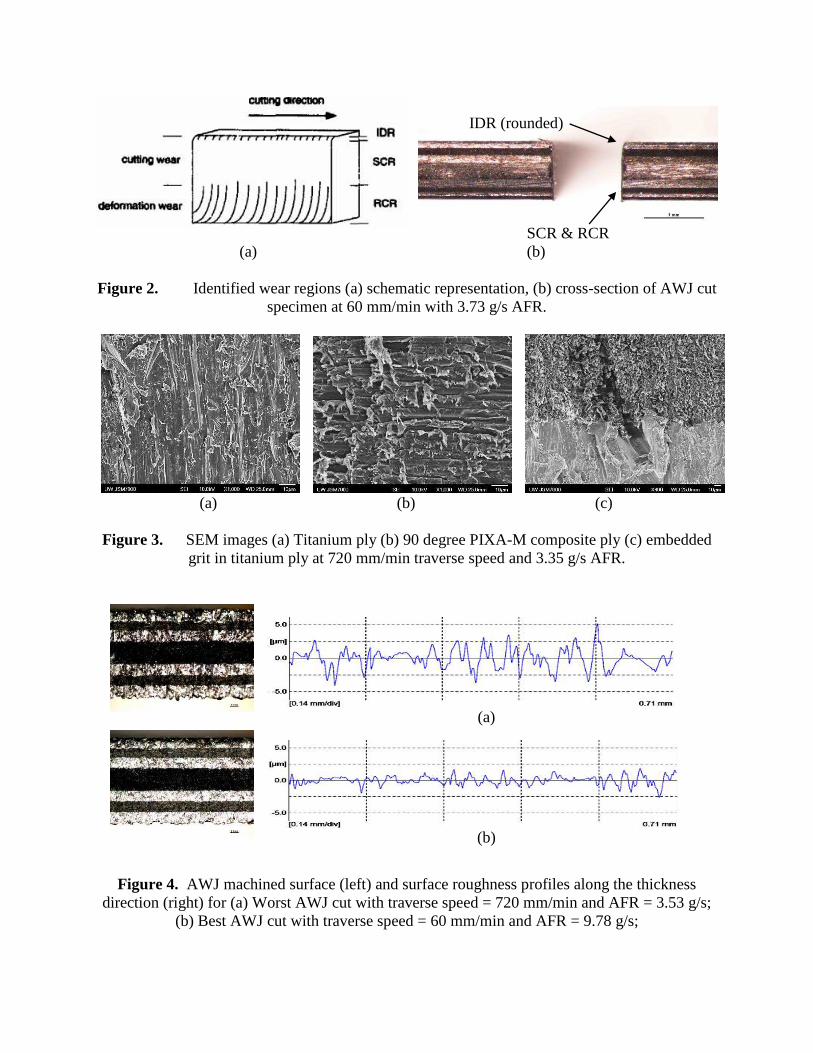
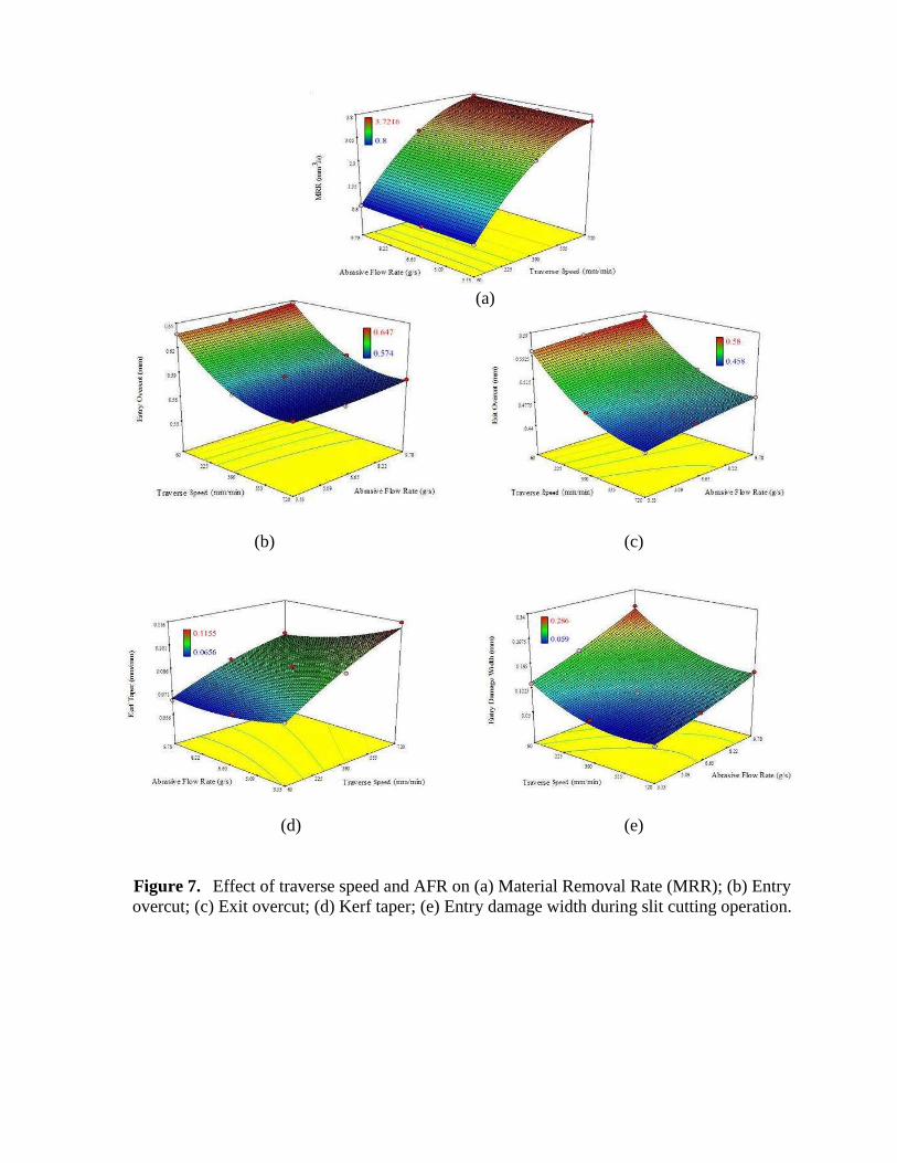
0.636 and 0.899 たm respectively. Surface profiles for both conditions are shown in Figure 4. The effect of cutting geometry on surface roughness was also investigated by comparing the straight cut surface roughness with trepanned surface roughness. The surface roughness for trepanned surfaces was observed between 0.662 and 0.671 たm. 3.2 Statistical Analysis of Machining Responses The observed machining responses are depicted in Table 4. The effect of process parameters on aforementioned machining responses is statistically analyzed by employing ANOVA (Analysis of variance) and the responses are modelled with regression analysis, governed by equations depicted in Table 5. In order to account for the credibility of analysis, the model was verified by plotting diagnostic curves i.e. normal probability and residual plots. A straight line in normal probability plot verified the distribution of residuals as Gaussian. A Residual vs Run plot was used to check for any consistent trends and thus periodically sustained error(s) in the experimentation. A random scatter of data points verified the absence of any time-related lurking variable(s) which could be traced back and blocked for a sound analysis. Residual versus Predicted value plot verified the model assumption of constant variance across the range of predictions. A constant variance is characterized by a randomly scattered data within the control limits and absence of any pattern. Besides, a leverage versus run was graphed to indicate the influence of each point in the model. If a point depicts a leverage of 1.0, then the point controls the model and model must go through that point. The plots for MRR model analysis are included in this discussion. However, similar observations were made for other model plots. Figure 5(a, b) depicts near normal distribution of residuals and absence of time dependent experimentation errors. Figure 6(a) depicts a constant variance model. A leverage versus run plot, shown in Figure 6(b) indicates the absence of one point dominance in the model. The ANOVA response models are shown in Figure 7 and listed in Table 5. Figure 7(a) indicates that an increasing jet traverse speed and decreasing abrasive mass flow rate contributed to higher MRR which can be explained with the reduced cutting time at the respective parameter settings. MRR was found to change significantly with traverse speed which is supported by its low P-value (7.80E-07) in the model, as depicted in Table 6. The parametric influence on overcut is shown in Figure 7(b, c). Overcut is observed to be more at jet entry side in comparison to exit side. This can be accounted to initial high energy abrasive jet at the entry side of the cut in the cutting wear zone which reduced with the depth of penetration. Model also delineated higher overcut at high AFR and low traverse speed. The kerf width was observed within the range of 1.15-1.3 times nozzle diameter (447-647 µm) at entry side and 0.92-1.16 times nozzle diameter (458-580 µm) at exit side.
Kerf taper was observed to be positive and within the absolute range of 0.065-0.115 mm/mm in the domain of chosen parameter values. Jet traverse speed exhibited a negative effect on the kerf taper, whereas Abrasive flow rate exhibited a positive effect, as depicted in Figure 7(d). ANOVA analysis showed traverse speed (P-value = 2.53E-03) and AFR (P-value = 2.58E-02) to be significantly contributive to the kerf taper response. Similar to overcut response, entry damage was observed within 59-286 µm, and showed positive trend when AFR was increased and traverse speed was reduced.
A low traverse speed increases jet exposure time and resulted in lesser amount of high energy abrasive particles impacting the work piece. This induced smoother kerf wall, smaller kerf taper, larger kerf width, and larger initial damage width. Effect of increasing AFR was similar to slowing down the traverse speed as increasing AFR would mean larger amount of abrasive particles exposed to the work piece per unit time performing the cutting operation. However, a balance between these two process variables was found critical. 4. SUMMARY AND CONCLUSION The straight cutting of Titanium Graphite fiber metal laminate sheet with Abrasive Water jet cutting was studied in this work. The effect of AWJ process parameters- jet traverse speed and abrasive flow rate on the cutting characteristics and process performance was investigated based on a fully crossed design of experiment scheme. ANOVA was employed for parametric optimization and predictive response models were established and verified based on the regression based statistical analysis for a chosen range of process variables. Machinability of TiGr was evaluated in terms of cutting time, material removal rate (MRR), overcut, taper and damage as machining responses. Traverse speed was found as a dominant factor in controlling these responses. The effect of slowing traverse speed was found similar to increasing AFR. Both result in larger amount of high energy abrasive particles impact the work piece per unit time. High MRR, small overcut, and damage could be obtained by using high traverse speed. However, high AFR should be used in order to get smooth surface finish and reduce kerf taper. The scope of the study is limited to thin sheets and the inspection of the effect of only two, but significant parameters – AFR and traverse speed. However, the variability in cutting performance may be achieved with the alteration of other feasible process variables viz. standoff distance, pressure, and nozzle geometry. The models cannot be projected to machining thicker laminate material where the effects of fiber layup and cutting profile are expected to be more pronouncedly influencing the jet energy distribution and its dissipation throughout the penetration depth, accounting for more sensitive control of the process parameters. 5. REFERENCES
1. Le Bourlegat, L. R., Damato, C. A., da Silva, D. F., Botelho, E. C., & Pardini, L. C. (2010).
Processing and mechanical characterization of titanium-graphite hybrid laminates. Journal of Reinforced Plastics and Composites, 29 (22), 3392–3400. Doi: 10.1177/0731684410377541.
2. Burianek DA, Giannakopoulos AE and Spearing SM. Modeling of facesheet crack growth in titanium–graphite hybrid laminates, Part I. Eng Fract Mech 2003; 70:775–798.
3. Burianek, D.A., Fatigue Damage in Titanium Graphite Hybrid Laminates, Master of Science Thesis, Department of Aeronautics and Astronautics, Massachusetts Institute of Technology, 1998
4. Ramulu, M., Stickler, P.B., and McDevitt, N.S., Influence of Processing Methods on the Tensile and Flexure Properties of High Temperature Composites, Composite Science and Technology, Vol. 64, 2004, pp. 1763-1772
5. Edward, L., Johnson, W.S., and Lowthere, S.E., An Evaluation of Two Fabrication Methods for Hybrid Titanium Composite Laminates, Composite Materials: Testing and Design, Vol. 13, 1997, pp. 202-214
6. Kim, D., and Ramulu, M., Cutting and Drilling Characteristics of Hybrid Titanium Composite Laminate, Transactions of NAMRI/SME, Vol. 33, 2005, pp. 445-452
7. Hashish, M.”AWJ Trimming of 787 Composite Stingers,” 2010 SAMPE Proceedings, Seattle, WA. www.sampe.orb 2010
8. Hashish., M., “AWJ Trimming and Drilling of Composite for Aircraft Structures, “Proceedings of the 9th Pacific Rim International Conference on Water Jetting Technology, November 20-23, 2009, Koriyama, Japan
9. Hashish, M., "Machining of Advanced Composites with Abrasive-Waterjets", Manufacturing Reviews, Vol. 2, No. 2, 1989, pp. 142-150
10. Arola, D., and Ramulu, M., A study of Kerf Characteristics in Abrasive Waterjet Machining of Graphite/Epoxy Composite, Journal of Engineering Materials and Technology, Vol. 118, April 1996, pp. 256-265
11. Connor, I., M. Hashish and M. Ramulu, “Abrasive Waterjet Machining of Aerospace structural Sheet and Thin Plate Materials”, Proceedings of 2003 WJTA Conference
12. Ramulu, M., Jenkins, M.G., and Guo, Z., Abrasive Water Jet Machining Mechanisms in Continuous-Fiber Ceramic Composites, Journal of Composites Technology & Research, JCTRER, Vol. 23, No. 2, April 2001, pp. 82-91
13. Hashish, M., (1995) “Waterjet Machining of Advanced Composites,” Materials and Manufacturing Processes, Marcel Decker, NY, Vol. 10, No 6, pp 1129-1152.
14. Hamatani, G. and Ramulu, M., Machinability of High Temperature Composites by Abrasive Waterjet, Journal of Engineering Materials and Technology, Vol. 112, Oct. 1990, pp. 381-386
15. Paul, S., Hoogstrate, A.M., Van Praag, R., 2002. Abrasive water jet machining of glass fibre metal laminates. J. Eng. Manuf. Part B 216, 1459–1469.
16. Edward, L., Johnson, W.S., and Lowthere, S.E., An Evaluation of Two Fabrication Methods for Hybrid Titanium Composite Laminates, Composite Materials: Testing and Design, Vol. 13, 1997, pp. 202-214.
17. Seo, Y.W., Ramulu, M., and Hashish M., Cost Analysis of Abrasive Waterjet Cutting: Thin Sheet Materials, Proceedings of SAMPE, Fall Conference 2005, (37th ISTC).
6. NOMENCLATURE 撃 Traverse speed in (mm/min) 兼岌 Abrasive flow rate (AFR) (g/s) t Time (s) V Volume of material removed (mm3) SOD Standoff distance (mm) MRR Material removal rate (mm3/s) W達探担 Width of cut (mm) d担誰誰狸 Tool diameter (mm) 穴勅津痛追槻 Jet entry diameter (mm) 穴勅掴沈痛 Jet exit diameter (mm) 系待-系泰 Empirical constants
7. TABLES
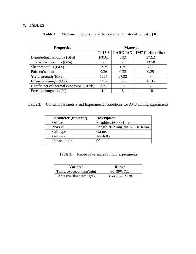
Table 1. Mechanical properties of the constituent materials of TiGr [16]
Properties Material Ti -15-3 LARC-IAX IM7 Carbon fiber
Longitudinal modulus (GPa) 100.61 3.33 272.2 Transverse modulus (GPa) - - 13.58 Shear modulus (GPa) 33.75 1.25 200 Poisson’s ratio 0.36 0.33 0.25 Yield strength (MPa) 1307 67.92 - Ultimate strength (MPa) 1459 105 36612 Coefficient of thermal expansion (10-6/k) 8.21 10 - Percent elongation (%) 4.1 6 1.8
Table 2. Constant parameters and Experimental conditions for AWJ cutting experiments
Parameter (constant) Description Orifice Sapphire, Ø 0.381 mm Nozzle Length 76.2 mm, dia. Ø 1.016 mm Grit type Garnet Grit size Mesh 80 Impact angle 90°
Table 3. Range of variables cutting experiments
Variable Range Traverse speed (mm/min) 60, 390, 720 Abrasive flow rate (g/s) 3.53, 6.23, 9.78
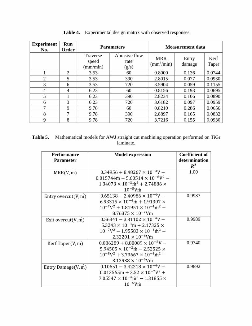
Table 4. Experimental design matrix with observed responses Experiment
No. Run
Order Parameters Measurement data
Traverse
speed (mm/min)
Abrasive flow rate (g/s)
MRR (mm3/min)
Entry damage
Kerf Taper
1 2 3.53 60 0.8000 0.136 0.0744 2 5 3.53 390 2.8015 0.077 0.0930 3 6 3.53 720 3.5904 0.059 0.1155 4 4 6.23 60 0.8156 0.193 0.0695 5 1 6.23 390 2.8234 0.106 0.0890 6 3 6.23 720 3.6182 0.097 0.0959 7 9 9.78 60 0.8210 0.286 0.0656 8 7 9.78 390 2.8897 0.165 0.0832 9 8 9.78 720 3.7216 0.155 0.0930
Table 5. Mathematical models for AWJ straight cut machining operation performed on TiGr laminate.
Performance Parameter
Model expression Coefficient of determination 三匝 MRR岫V┸ m岻岌 ど┻ぬねひのは 髪 ぱ┻ねぱにはば 抜 など貸戴V 伐ど┻どなのばねねm岌 伐 の┻はどのなね 抜 など貸滞V態 伐な┻ぬねどばぬ 抜 など貸戴m岌 態 髪 に┻ばねぱぱは 抜など貸泰Vm岌
1.00
Entry overcut岫V┸ m岻岌 ど┻はのなぬぱ 伐 に┻ねどひぱは 抜 など貸替V 伐は┻ひぬぬなの 抜 など貸替m岌 髪 な┻ひなぬどば 抜など貸胎V態 髪 な┻ぱなひのな 抜 など貸替m岌 態 伐ぱ┻ばはぬばの 抜 など貸胎Vm岌 0.9987
Exit overcut岫V┸ m岻岌 ど┻のはぬねな 伐 ぬ┻ぬななどに 抜 など貸替V 髪の┻ぬにねぬ 抜 など貸戴m岌 髪 に┻なばぬにの 抜など貸胎V態 伐 な┻ひののぱぬ 抜 など貸替m岌 態 髪に┻ぬににどな 抜 など貸滞Vm岌 0.9989
Kerf Taper岫V┸ m岻岌 ど┻どぱはにぱひ 髪 ぱ┻ぱどどぱひ 抜 など貸泰V 伐の┻ひねのどの 抜 など貸戴m岌 伐 に┻のにのにの 抜など貸腿V態 髪 ぬ┻ばぬははば 抜 など貸替m岌 態 伐ぬ┻なにひぬぱ 抜 など貸滞Vm岌 0.9740
Entry Damage岫V┸ m岻岌 ど┻などはのな 伐 ぬ┻ねにになぱ 抜 など貸替V 髪ど┻どなぬのはのm岌 髪 ぬ┻のに 抜 など貸胎V態 髪ば┻どののねば 抜 など貸替m岌 態 伐 な┻ぬなぱのの 抜など貸泰Vm岌 0.9892
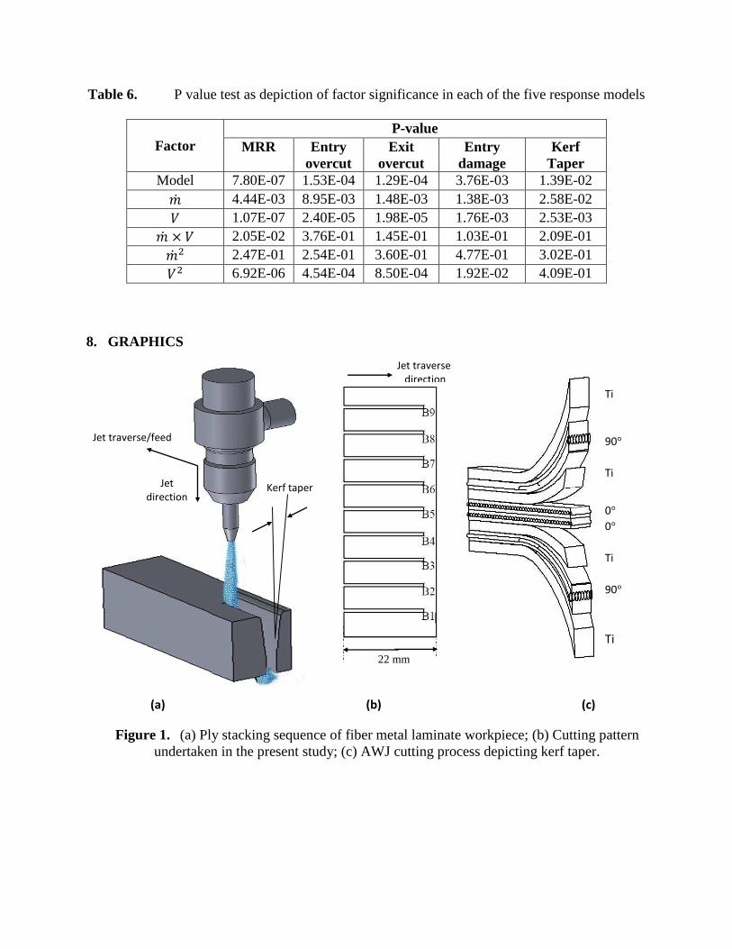
Table 6. P value test as depiction of factor significance in each of the five response models
Factor P-value
MRR Entry overcut
Exit overcut
Entry damage
Kerf Taper
Model 7.80E-07 1.53E-04 1.29E-04 3.76E-03 1.39E-02 兼岌 4.44E-03 8.95E-03 1.48E-03 1.38E-03 2.58E-02 撃 1.07E-07 2.40E-05 1.98E-05 1.76E-03 2.53E-03 兼岌 抜 撃 2.05E-02 3.76E-01 1.45E-01 1.03E-01 2.09E-01 兼岌 態 2.47E-01 2.54E-01 3.60E-01 4.77E-01 3.02E-01 撃態 6.92E-06 4.54E-04 8.50E-04 1.92E-02 4.09E-01 8. GRAPHICS
Figure 1. (a) Ply stacking sequence of fiber metal laminate workpiece; (b) Cutting pattern undertaken in the present study; (c) AWJ cutting process depicting kerf taper.
Kerf taper
Jet traverse/feed
Jet
direction
Ti
90°
Ti
0°
0°
Ti
90°
Ti
Jet traverse
direction
(a) (b) (c)
22 mm
IDR (rounded)
SCR & RCR (a) (b)
Figure 2. Identified wear regions (a) schematic representation, (b) cross-section of AWJ cut
specimen at 60 mm/min with 3.73 g/s AFR.
(a) (b) (c) Figure 3. SEM images (a) Titanium ply (b) 90 degree PIXA-M composite ply (c) embedded
grit in titanium ply at 720 mm/min traverse speed and 3.35 g/s AFR.
(a)
(b)
Figure 4. AWJ machined surface (left) and surface roughness profiles along the thickness
direction (right) for (a) Worst AWJ cut with traverse speed = 720 mm/min and AFR = 3.53 g/s; (b) Best AWJ cut with traverse speed = 60 mm/min and AFR = 9.78 g/s;
Figure 5. (a) Normal plot of residuals; (b) Residuals versus Run plot.
Figure 6. (a) Residual versus predicted; (b) Leverage versus Run plot.
Color points bMRR:
3.7216
0.8
Residuals
No
rm
al
% P
ro
ba
bil
ity
Normal Plot of Residuals
-0.015 -0.01 -0.005 0 0.005 0.01 0.015
1
5
10
20
30
50
70
80
90
95
99
Run Number
Re
sid
ua
ls
Residuals vs. Run
-0.015
-0.01
-0.005
0
0.005
0.01
0.015
1 2 3 4 5 6 7 8 9
Run Number
Le
ve
ra
ge
Leverage vs. Run
0.00
0.20
0.40
0.60
0.80
1.00
1 2 3 4 5 6 7 8 9
Color points bMRR:
3.7216
0.8
Predicted
Re
sid
ua
ls
Residuals vs. Predicted
-0.015
-0.01
-0.005
0
0.005
0.01
0.015
0 1 2 3 4
(a) (b)
(a) (b)
(a)
(b) (c)
(d) (e)
Figure 7. Effect of traverse speed and AFR on (a) Material Removal Rate (MRR); (b) Entry overcut; (c) Exit overcut; (d) Kerf taper; (e) Entry damage width during slit cutting operation.


![[PPT]Abrasive Waterjet Machining - Southern Illinois …scho/index_files/Abrasive Waterjet.ppt · Web viewTitle Abrasive Waterjet Machining Author Academic Computing Last modified](https://img.pdfslide.us/doc/110x75/5aa4961d7f8b9ac8748c252d/pptabrasive-waterjet-machining-southern-illinois-schoindexfilesabrasive.jpg)