Embed Size (px)
Citation preview

1
Precision Attitude and Translation Control Design and Optimization
John Mester
Hansen Experimental Physics Laboratory, Stanford University, Stanford, California, U.S.A.
Abstract
Future fundamental physics and astrophysics missions will require spacecraft attitude and translation controlof unprecedented precision. Design and on-orbit optimization of the Gravity Probe B attitude andtranslation control system necessitated the development of unique spacecraft simulation facilities that cannow be leveraged to model high accuracy attitude control, drag free control, and payload-spacecraftinteraction dynamics to enable new mission concepts. In this paper we describe ongoing and proposedefforts to apply state of the art simulation techniques to two specific missions, LISA Pathfinder and STEP.
Keywords: drag-free, relativity, simulation, spacecraft control, hardware-in-the-loopPACS: 95.55.Aq, 95.55.Aw
INTRODUCTION
This paper details the application of the Stanford University Precision Attitude and TranslationControl Design and Optimization program to two missions, LISA Pathfinder and STEP. For thecase of LISA Pathfinder we have initiated a collaboration with the LISA Pathfinder missionteam and have proposed a three-year program to develop precision attitude and translationcontrol simulators and to develop and test in-space optimization commands. For the case ofSTEP, the Precision Attitude and Translation Control Design and Optimization program is usedto create high fidelity models of the STEP drag free control system for use in the ongoingdevelopment of the STEP comprehensive error model.
Future space missions will require spacecraft attitude and translation control of unprecedentedprecision. Missions requiring Drag Free Control, such as ST7/LISA Pathfinder, LISA. STEP,and BBO, rely on inertial sensors of such high sensitivity that their full performance can only berealized after launch. LISA, and Interferometric Synthetic Aperture Radar missions requiremultiple spacecraft formation flying providing new challenges for attitude and translationcontrol design. Control of the Altair Lunar Lander must account for possible liquid fuel sloshand center of mass motion during vehicle maneuvers.
These challenges levee two prerequisites for mission implementation, 1) development of highfidelity attitude and translation control simulations and 2) development of procedures for in-space optimization of satellite control and on-board instruments. What sets these challengesapart from conventional spacecraft is the complex interaction dynamics of vehicle control withon-board systems - be they motion of inertial reference sensors or liquid propellants.
The Hansen Laboratory Precision Attitude and Translation (PAT) Control Program leverages

John Mester [email protected]
Stanford University’s unique experience in having successfully flown the world’s only three-axis drag free satellites, Discos/Triad launched 1972 and Gravity Probe B launched 2004. GP-Bemployed high precision attitude and roll control - active control of six degrees of freedom.
The PAT Control Program focuses on high accuracy attitude control, drag free control, andpayload-spacecraft interaction dynamics. On-going efforts include the implementation ofadvanced spacecraft environment and dynamics models, development of spacecraft and payloadsensor and actuator models, error modeling, parameter identification, state estimation, controlalgorithm design, and command template formation to establishing realistic expectations andplan post-launch tuning and optimization.
Specific implementation goals:
1 Development of fully integrated sensor-controller-actuator simulations, operating acrossthe payload/spacecraft interface
2 Exploitation of existing modular architecture to enable efficient exchange of softwaremodels for hardware units (either in the form of prototype or final flight electronicssystems) for hardware-in-the-loop verification
3 Employment of a high fidelity spacecraft bus and flight CPU to enable flight softwarevalidation and verification with the science payload.
4 Integrated Mission Operations consoles for command generation and verification andoperations training.
Current collaborations include ZARM, University of Bremen, Germany, and ICRANet, PescaraItaly to develop drag-free simulators for GAIA and STEP. We are also working together withMLDesigner Technologies and Telelogic Inc. to enhance mission level simulation capabilitiesand to incorporate requirements tracking.
LISA Pathfinder
We propose a three-year program to develop precision attitude and translation control simulatorsand to develop and test in-space optimization commands with an emphasis on LISA Pathfinderand LISA missions. LISA Pathfinder PI and LISA International Science Team member, Prof.Stefano Vitale, will serve as Project Advisor. Prof. Vitale will provide interface to LISAPathfinder/LISA technical data, including control design and requirements definition, on a no-exchange-of-funds basis.
The proposed work leverages Stanford University’s unique experience in having successfullyflown the world’s only three-axis drag free satellites, Discos/Triad, launched in 1972 andGravity Probe B, launched in 2004. GP-B, under MSFC leadership, also employed highprecision attitude and roll control - active control of six degrees of freedom. Proposal PI,Professor Dan DeBra, served as Principal Investigator for DISCOS and Co-PI for GP-B.

John Mester [email protected]
Objectives
The proposed program will leverage an integrated payload and spacecraft simulation systemdeveloped for the Gravity Probe B Relativity Mission by expanding its capabilities for needs ofLISA and LISA Pathfinder missions. Specific implementation goals include:
In this proposal we are looking to build a LISA Pathfinder simulation in our new missionsimulation facility. The goals set out below can be achieved without the need for any newcapital equipment:
• Create a LISA Pathfinder spacecraft dynamic model in an MLDesigner (MDL) softwareframework
• Create LISA mission dynamic model in MLD• Model LISA/LISA Pathfinder data stream per design• Verify LISA Pathfinder simulation model using mission requirements and specifications.• Explore control loop coupling• Add “non-ideal” models (i.e. proof mass charge, micrometeorite strikes, etc.)• Compare proof mass suspended vs proof mass unsuspended performance
• Develop and test in-space tuning protocols and command structure and testimplementation with simulator
• Evaluate ultimate LISA/LISA Pathfinder drag-free performance with simulator• Compare with ESA simulation results• Test ESA developed in-space tuning protocols.
Technical Background
The range of implementation goals for this proposal is based on flight experience with drag freecontrolled satellites. To date, two three-axis drag free controlled satellites have flownsuccessfully. The first, TRIAD I, managed by the Johns Hopkins University Applied PhysicsLaboratory, was launched September 2, 1972. Three-axis translation control (drag free control)was achieved using the DISCOS (Disturbance Compensation System) built by StanfordUniversity under the direction of Prof. Daniel DeBra. The DISCOS system enabled thespacecraft to “follow” an internal, shielded, inertial sensor to compensate for the disturbancesfrom aerodynamic drag, magnetic torques, gravity gradient torques, and radiation pressure. Thesecond three-axis translation controlled satellite, Gravity Probe B, was launched April 20, 2004and has successfully completed its science data phase. In addition to three-axis translationcontrol, GP-B is simultaneously under precision attitude control so all six spacecraft degrees offreedom are controlled. For both missions a macroscopic sphere is used as the inertial sensor(PtAu alloy for DISCOS, quartz for GP-B). A detailed analysis of GP-B flight data has shownthat the dynamics of the inertial sensor couple to the spacecraft dynamics in a complexway[1,2,3]. This has the effect of increasing the number of degrees of freedom under control:that is, one must simultaneously control the spacecraft degrees of freedom plus the relevantsensor degrees of freedom. For Gravity Probe B this means the ATC (attitude and translationcontrol system) must control nine degrees of freedom, the full six spacecraft and the threetranslational DOF for the sensor. Lessons learned from these missions, presented below,indicate that high fidelity simulations are an essential tool for successful controller operation andtuning.

John Mester [email protected]
Lessons Learned from Drag Free Controlled MissionThe Gravity Probe B satellite actively monitors and controls 9 interacting degrees of freedomduring normal operation:
A. 3 in orientation of the space vehicle to keep the tracking telescope pointed at theguide star and maintain a constant roll rate and fixed roll phase with respect to theorbital plane
B. 3 in translation of the space vehicle to keep the vehicle in a drag-free orbit about thegeometric center of the one of the science gyro’s housing cavities
C. 3 in translation of the gyroscope rotor with respect to the housing cavity
The other 9 degrees of translation freedom of the remaining 3 gyroscopes are slaved to the first9 described above and do not significantly interact with the dynamics of the vehicle as a whole.Note that the rotational degrees of freedom of the gyroscopes are not controlled by design.
One gyro serves as the drag-free sensor (accelerometer) for the satellite. The three controlefforts required to keep the gyroscope rotor centered in its housing are fed to the space vehicle.The space vehicle, in turn, applies compensating forces via its thruster set to null the forces feltby the gyroscope rotor. See Figure 1. These six degrees of freedom significantly interact. Thegyroscope position control loop bandwidth (Gyroscope Suspension System or GSS) is madesmall to minimize disturbance torques on the rotor, and is on the order of 2 Hz. The spacevehicle ATC system bandwidth is of the same order and is limited by thruster authority andATC processing. These two control loops interact significantly during operation.
ATCP+I Controller
Resonance Modes
+ +
2
1
Ms
+
Position Bridge
Vehicle dynamics
GSS Controller
2
1
ms
Gyroscope dynamics
+
+
Gravity Gradient feed forward
GSS Ctrl Effort
K1K2
Gyro Position
SV Position
+
-
-
GSS System
ATC System
Space Vehicle Dynamics
Ext Distur -bances
+
Ext Disturbances
SV Ctrl Effort
R
�
r
�
u
�
U
�
() rR ?
�
�
() rR ?
�
�
R
�
r
�
Additional coupling between the translational DOF comes from orientation changes. The centerof mass of the vehicle is not at the center of the drag free sensor’s housing, thus any change inorientation tends to be about the center of mass of the vehicle. The drag-free action nulls theseorientation induced forces and thus moves the effective center of mass of the vehicle to thecenter of the drag free sensor’s housing. Again, the orientation control loop bandwidth is thesame as the translation control bandwidth and thus this control loop, as well, interactssignificantly with the gyro suspension control loop.
Figure 1: Interacting degrees of freedom

John Mester [email protected]
This brief overview shows, in outline form, that the 9 degrees of freedom are strongly coupledin normal operation and thus cannot be easily separated into simpler and isolated controlsubsystems.
Gravity Probe B on-orbit drag-free performanceThe Gravity Probe B satellite provides the science satellite community with the state of the artdemonstration of drag-free technology to date[2,3]. The GP-B drag-free system reduced thegravity gradient and environmental forces acting on the spacecraft by a factor of 10,000 bysimultaneously controlling 9 degrees of freedom (6 of the spacecraft and 3 of the gyroscopesuspension system).
Figure 2 – Drag-free performance showing vehicle and gyroscope accelerations.
The ATC system was programmed to implement two different forms of drag-free control, thePrime and suspended or accelerometer mode. In the Prime mode the gyroscope suspensionsystem (GSS) releases control of the rotor position allowing it to float freely in the housing. Therotor position is sent to the ATC where it was included in the closed loop control of thespacecraft. The spacecraft now flies an orbit such that the rotor position does not exceed 4micrometers off-center otherwise the gyroscope suspension system reacquires control and opensthe drag-free loop. As the proof mass rotor is ideally shielded from all external forces, byfollowing it the spacecraft maintains a perfectly gravitational orbit. This was the intended modeof operation and was in fact demonstrated on orbit.

John Mester [email protected]
The suspended drag-free mode has the GSS maintain control of the rotor position and sends thecontrol efforts needed to keep the gyroscope centered to the ATC. The ATC then adjusts itscontrol of the spacecraft such that the GSS control efforts are minimized.
The two modes of drag-free control demonstrated on orbit are shown in Figure 3 –In the end itwas the suspended mode of drag-free operation that was chosen for both performance and riskmitigation reasons.
Figure 3 – Comparison of suspended drag-free, unsuspended drag-free and drag-freeoff
Although ATC setup and tuning was more complex than anticipated by the completion of theInitial Operations Checkout phase the missions stringent drag free and attitude controlrequirements were met. The fundamental conclusion of the Gravity Probe B lessons learnedstudy is that high fidelity simulation capability played an essential roll in the successfuloperation and tuning of the GP-B attitude and translation control system.

John Mester [email protected]
Future missionsFuture missions pose even greater ATC challenges for the following reasons.
1 The drag free control requirements are more stringent. Drag free residual accelerations inmeasurement bandwidth: GP-B 5x10-12 g
STEP 1x10-14 gST7 1x10-15 gLISA 1x10-16 g
2 Complexity of inertial sensor. DISCOS and GP-B used a sphere requiring a suspensionthat controlled just the three translational DOF. STEP, ST7 and LISA have inertialsensors of belted cylindrical or cubical shape that require six DOF sensor control. Inaddition STEP, ST7 and LISA also use 2 masses per inertial sensor package thusrequiring 12 DOF of sensor control in addition to the spacecraft DOF.
3 Formation flying requirements. The LISA mission consists of 3 independent drag freeand attitude controlled spacecraft flying in formation with additional requirements ontheir relative distance.
4 Operations Limits. As stated previously the on orbit setup and tuning of the GP-B ATCsystem occurred during an IOC phase lasting 4 months. Such a long set-up phase maynot be advised for missions of shorter duration than GP-B, e.g the entire STEP mission isproposed to last 6 months. Further the low earth orbit of GP-B enables frequentcommunication through the TDRSS network and ground stations. Ten thousandcommands were sent during the setup phase. ST7 will be launched into the L1 Lagrangepoint while LISA will be in orbit around the sun trailing the earth by 20 deg. Ascompared with GP-B, this will lead to significantly reduced communicationsopportunities; high fidelity hardware-in-the-loop simulation will be an essential elementfor success.
Given the increased complexity and more limited communications opportunities future missionsrequiring attitude and translation control demand a robust simulation capability.
On-Going Work
Our Stanford University attitude and translation control group has an ongoing program onmission simulation for the STEP (Satellite Test of the Equivalence Principle) mission. Asignificant part of this effort has been spent on designing the mission simulation for STEPincorporating these lessons learned from their experience in getting GP-B control system tomeet requirements. The project has been divided into two efforts, one to validate the dynamicsof a drag-free simulation using GP-B flight data and the other to build the mission simulation forSTEP around a powerful software package. The validation of the drag-free simulator is beingcarried out under a collaborative effort between (ZARM), Zentrum Angewandte Raumfahrt-technologie und Mikrogravitation, University of Bremen, Germany, Stanford and others. Thisproject is supported by a Marie Curie grant from the European Union and is managed by ZARMunder the name of First Look[4]. The objective of the First Look team is to design and build ageneric drag-free simulator that can support future drag-free missions in the area of systemidentification. The Stanford University collaboration enables the use of flight data to validatetheir generic drag-free simulator. Stanford will also be active in the project beyond this

John Mester [email protected]
validation phase. Once the generic simulator has been validated a STEP drag-free controllerwill be built inside the generic simulation. This work is made possible by the financial supportof ICRANet, the International Center for Relativistic Astrophysics Network.
The STEP mission simulation incorporates facilities inherited from GP-B, the integrated testfacility and parts of the mission operations center, and adds to these a new mission simulationfacility. The core software chosen to build the mission simulation is ML Designer. This softwaretool can best be described as providing the functional modeling capability of Matlab and addingto that the ability to model system architectures and build executable simulations.
Proposed Work
In this proposal we are looking to build a LISA Pathfinder simulation in our new missionsimulation facility. The goals set out can be achieved without the need for any new capitalequipment.
Year 1:• Complete GP-B simulator validation and port relevant components to ML Designer.• Complete generic spacecraft ATC simulation in MLD software, vet against GP-B flight
data• Create LISA Pathfinder spacecraft dynamic model in MLD• Create LISA mission dynamic model in MLD
Year 2:• Model LISA/LISA Pathfinder data stream per design• Verify LISA Pathfinder simulation model using mission requirements and specifications.• Explore control loop coupling• Add “non-ideal” models (i.e. proof mass charge, micrometeorite strikes, etc.)• Compare proof mass suspended vs proof mass unsuspended performance
Year 3:• Develop and test in-space tuning protocols and command structure and test
implementation with simulator• Evaluate ultimate LISA/LISA Pathfinder drag-free performance with simulator• Compare with ESA simulation results• Test ESA developed in-space tuning protocols

John Mester [email protected]
Technical Approach
We propose to build the LISA Pathfinder drag-free satellite into our mission simulation facilityand support pre and post launch investigations into the performance of its drag-free system. Theexperience gained during the Gravity Probe B mission will be incorporated into this simulationin the form of designing test cases that reproduce challenges faced during its mission as well asengineering best practices identified. We will examine control loop interactions, operationalefficiencies, data acquisition strategies and performance optimization of Pathfinder’s drag-freesystem. This will enable the most efficient technology exchange in that the experience gained inexecuting the only 6 degree of freedom drag-free satellite to date will be expressed directly inthe context of the LISA Pathfinder mission’s objectives. As the Pathfinder mission is technologydemonstration for LISA, the exchange can naturally be extended to the LISA mission engineers.
The Stanford simulation facility has been enhanced since the completion of GP-B and during athree year collaboration with ZARM, University of Bremen, Germany. The enhancement enablethe construction of a new simulator at Stanford that allows users to build executablearchitectural models capable of investigating complex system interactions. Both efforts aremature and ready to be applied to the Pathfinder mission.
The work with ZARM has been to build a generic drag-free satellite simulation to supportsystem identification both prior to launch, in the development phases of a mission, and postlaunch to efficiently identify and tune the drag-free control loops in situ. It has been supportedby a grant from the European Union and will continue for another year. The continuedcollaboration will augment our Pathfinder effort since the ZARM organization was a centralparticipant in the design of Pathfinder’s drag-free controller. Currently, this generic drag-freesimulator is finishing up a year long project whereby Stanford’s Gravity Probe B drag-freesimulator has been integrated with the generic simulator and has been used to validate thissimulator’s performance against GP-B flight data. Once this validation is complete we intend toport this technology into Stanford’s mission simulation facility.
The diagram below (figure 4) describes the simulation architecture of Stanford’s missionsimulation facility. Its shows how we are able to build the simulation consisting of models thesatellite with decreasing levels of abstraction. A full implementation of the architecture wouldinclude hardware function verification however our approach will necessarily be exclusivelysoftware in nature as we see no mechanism for obtaining the representative hardware forhardware in the loop implementation. This could be added in the future should the Pathfinderteam deem it value added.

John Mester [email protected]
Verification & Impl. Details
Common Executable System SpecificationMission Level
(Environment, Use Cases) ?
System Level ?
LISA Pathfinder Spacecraft Model
Operational Requirements
Sensor and Actuator Models
Implementation Level(C, VHDL)?
Formalization & Design Validation
Synthesis
SimulativePerformance
Analysis
ConstraintBased
Verification
Figure 4.Simulation implementation description.
We describe here the approach according to figure 4.
Operational Requirements
The operational requirements form the basis for the simulation design. This is a description ofthe LISA Pathfinder mission at the highest level of abstraction. It will describe the orbit,operational constraints, mission modes, communication protocols among other features. Thisinformation constrains the overall design of the simulation
Mission Level
At the mission level are functional models that provide the spacecraft simulated interaction withits environment. Examples of this are solar pressure, a gravitational model, impulsiveaccelerations due to impacts and other external sources of disturbance. It requires that a finiteelement model of the spacecraft be available to include dynamics interaction between thePathfinder spacecraft and its environment. It can also include models to investigate anomalousconditions such as component failures or out of specification vehicle configurations.
System Level
The spacecraft and subsystems are modeled at the system level. It is at the system level that thedynamics of the Pathfinder spacecraft, functionally modeled by its sensors and actuators, areverified. Each of the subsystems are modeled individually and verified against their respectivespecifications. They are then attached to the spacecraft model where the coupling, both to thespacecraft and each other, are modeled. The incorporation of the GP-B flight experience will beincorporated almost exclusively in this block.The simulator’s capability to simultaneously simulate using multiple domains will allow us tomodel the spacecrafts communications bus along with the electronics. This will enable thesimulation to be used for investigations in to data acquisition and telemetry formats. Once the
John Mester [email protected]
dynamic interactions of the Spacecraft and payload have been verified and the data flowincluded in the models we will be able to explore control loop interactions and operationalconsiderations.
Implementation Level
Once each of the simulation models are in place and the the system has been verified thesimulation can be executed. At this point it is ready be used for engineering studies.
Facility Description
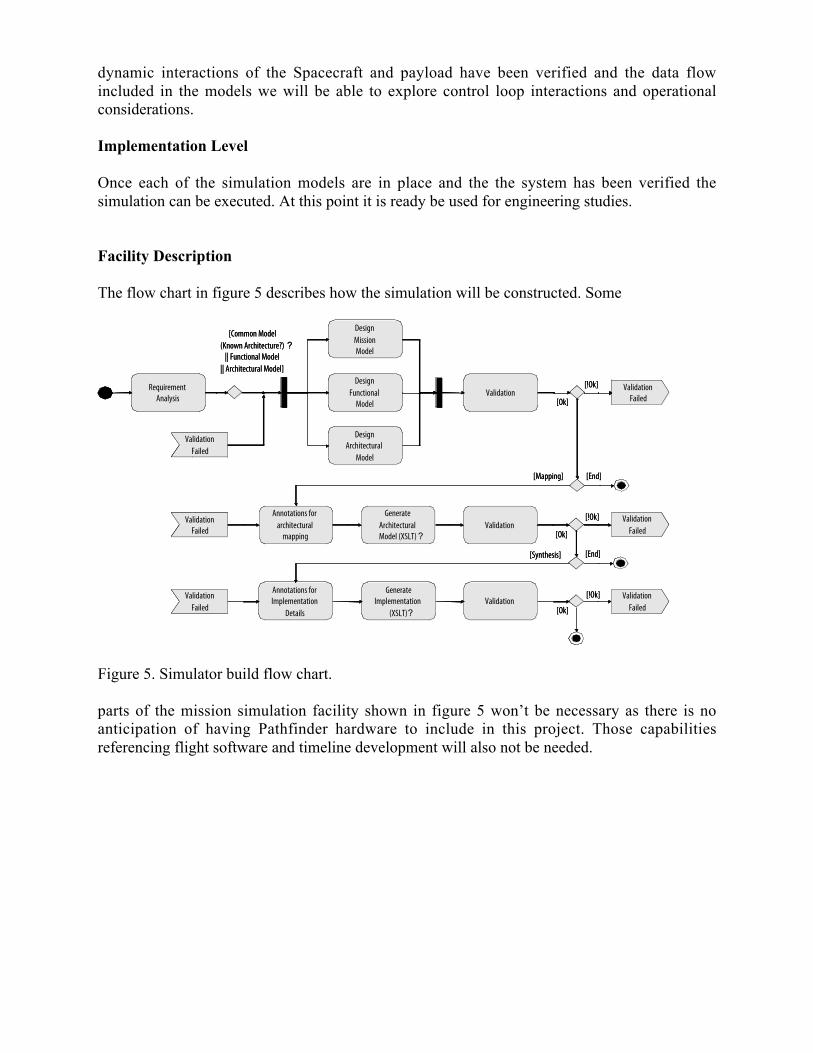
The flow chart in figure 5 describes how the simulation will be constructed. Some
RequirementAnalysis
DesignMissionModel
DesignFunctional
ModelValidation
DesignArchitectural
Model
[Common Model(Known Architecture?) ?
|| Functional Model|| Architectural Model]
Annotations forarchitectural
mapping
GenerateArchitecturalModel (XSLT)?
Validation
GenerateImplementation
(XSLT)?
Annotations forImplementation
DetailsValidation
ValidationFailed
[End][Mapping]
[End][Synthesis]
[Ok]
[!Ok]
[Ok]
[!Ok]
[Ok]
[!Ok]
ValidationFailed
ValidationFailed
ValidationFailed
ValidationFailed
ValidationFailed
ValidationFailed
ValidationFailed
ValidationFailed
Figure 5. Simulator build flow chart.
parts of the mission simulation facility shown in figure 5 won’t be necessary as there is noanticipation of having Pathfinder hardware to include in this project. Those capabilitiesreferencing flight software and timeline development will also not be needed.

John Mester [email protected]
Figure 6. Block diagram of Stanford mission level simulation facility.
Spacecraft simulation design and verification methodology
1. Start with core spacecraft model: point mass in orbit.– Simulation core– Contains space environment models and 6 DOF ATC core.
2. Build the basic space vehicle in software– Add basic models of sensors, actuators, instruments to sim core – give the vehicle
extent.– Perform trade and performance studies.
3. Space Vehicle Design Refinement– Control definitions of interfaces, partitions, and functions.– Increase fidelity of models in parallel with hardware if made available– Execute operations plans
4. Pre-launch preparations– SW V&V, HW performance and acceptance testing– Mission Operations testing
5. Post-launch support– “Truth model” of the space vehicle – update sim to as-observed performance.– Rapid performance evaluation and anomaly resolution.– Data analysis support for Pathfinder and LISA teams.
Details of the Approach:
The work we propose here is to continue to develop and formalize this approach to spacecraftdesign and verification. This methodology is valuable to the development of all space missions,

John Mester [email protected]
however, we plan to focus the effort around the LISA Pathfinder mission as it is the next drag-free mission to launch.
This particular focus conveys a number of advantages to this research effort:
• The drag-free satellite is naturally a complex system with interacting dynamics that havebeen successfully deployed (i.e. DISCOS and GP-B) that can serve as the canonicalmodel of a complex, interacting system.
• Gravity Probe B has available 12 months of on-orbit performance data operating in thedrag-free configuration and the vehicle itself will be available for additional on-orbitstudies – as well as ground based studies with flight equivalent hardware. This sort ofoperational data is very valuable to compare models with a real vehicle’s performance.
• This research effort will be coordinated with other spaceflight missions using drag-freetechnology under investigation here at Stanford University
These features taken together give this research project particular relevance by makingsubstantive contributions to the next drag-free mission while formalizing and extending ourmission development approach.
This research effort will do the following:
1) Create a Kinematic Software Simulator for the Pathfinder Mission
Develop mission level software simulations of the Pathfinder single-spacecraft including;
• Space vehicle kinematic models (18 degrees of freedom)• Space vehicle sensors and actuators (thrusters, control gyroscopes, star trackers)• Proof mass dynamic models and suspension/readout systems models.• Space environmental effects (solar wind, atmospheric drag, magnetic fields, etc)• Prototypical data flow and data acquisition to support the analysis before and after the
launch
The products of this phase are:
• Functional software-based baseline spacecraft models• A formalized and vetted framework by which all the dynamic elements of the vehicle
interact and through which external disturbances can be added or modified. Thisframework solves the coordination and communication issues between multiplecomputer tools and computer platforms that comprise the overall simulation system.
2) Operations planning and prototyping.
Use the mission simulation to develop and optimize prototypical operations plans and to deploy,test, calibrate, and configure the drag-free system. These prototypes will use realisticsimulations of the communication and data-processing constrains of Pathfinder’s missionoperations control center.

John Mester [email protected]
The products of this phase: An enhanced integration framework that includes the realisticconstraints of a mission ops center and space/earth communication links. This will bedemonstrated with prototypical command sequences from the reference missions under study.
3) Data
In summary, the results of this research effort are to establish a software model of the LISAPathfinder of the design of a complex satellite with multiple interacting dynamic systems. Theend-to-end communications models This approach additionally lowers on-orbit schedule riskpermitting the development and iteration of the operational plans and command loads on thehigh-fidelity vehicle model prior to deployment.

John Mester [email protected]
STEP
STEP, the Satellite Test of the Equivalence Principle, is a fundamental physics experiment inspace originally conceived in 1971 and studied in detail since 1990 jointly and separately byESA and NASA. STEP’s purpose is to test the apparent equivalence of gravitational and inertialmass with greatly increased precision. Also referred to as the Principle of Universality of FreeFall, the Equivalence Principle is the assertion that in a uniform gravitational field free of otherforces two bodies of different composition will fall with the same acceleration. Although theprinciple has been confirmed in ground-based experiments and lunar laser ranging observationsto within several parts in 1013 [5,6,7] there are strong theoretical grounds for seeking violationsat lower levels [8] STEP will advance the testing of equivalence by more than five orders ofmagnitude to approximately one part in 1018. A non-null result would effectively constitute thediscovery of a new fundamental force in nature. A null result would greatly strengthen the basisof Einstein's theory, and place new and challenging limits on alternative theories.
The STEP payload contains four sets of differential accelerometers based on superconductingtechnology mounted in a superfluid helium dewar operating at a temperature of 1.8K. Thesatellite orbits at ~500 km with inclination of 97.3º; i.e. a sun synchronous orbit. The roll of theSpace craft can be varied between –3 to 3 times the orbit rate. This brings the EquivalencePrinciple signal frequency, ωEP = ω 0rbit – ω roll, away from the orbit frequency where manydisturbances occur. Boil-off of the helium cryogen powers proportional thrusters which areused to actuate a drag free control system to minimize disturbances. Cryogenic operations alsoallow the use of SQUIDs which provide an extremely sensitive means of detection ofdifferential and common mode acceleration.
Drag Free Control
STEP requires high performance dragfree control to reduce external disturbances. Active dragcompensation shall reduce satellite acceleration by seven orders of magnitude and will controlsatellite attitude to minimize gravity gradient forces at the other accelerometers.
STEP will use a virtual proof mass defined be the common mode signal of a test mass pair.Optimized algorithms for Drag Free and Attitude control and related temperature control havebeen developed from Triad and GPB experience and a series of studies conducted by the STEPcollaboration [9,10,11] The DFC will control acceleration levels at the proof massaccelerometer to better than 2 x 10 –14 m/sec2
at signal frequency, and will control satelliteattitude to minimize gravity gradient forces at the other accelerometers. STEP has no pointingrequirement to an external reference in the usual sense. Rather, the satellite attitude will becontrolled to minimize disturbances from gravity gradients. Similarly, there will be no orbitcorrection since the DFC naturally follows the desired orbit. Dewar temperature will beregulated below 2.1 K by the DFC algorithm, keeping systematic variations at signal frequencyat minimal levels.
Sensor Inputs
The DFC system will use the differential accelerometer common mode SQUID signal andelectrostatic system measurements, with minor inputs from a star tracker, sun sensor andmagnetometer. These inputs drive an extended Kalman filter that estimates the remainingobservable variables using the inputs and measured satellite and orbit properties. The DFC

John Mester [email protected]
control law operates on the resulting state vector to generate commands for the actuators, whichinclude thrusters, magnetic torquers, and a heater to control the Dewar boil-off. The actuatorscancel disturbances, keeping the accelerometers near zero output and the temperature nearnominal.
Proportional Thrusters
Sixteen proportional helium thrusters will be mounted on struts from the Dewar in clusters offour in a fully redundant, optimized configuration. The struts for the thrusters reduce plumeimpingement, are thermally isolating, and in addition provide a larger moment arm for attitudecontrol. Helium gas from the Dewar vents into a gas manifold which distributes it to thethrusters. The thrusters will both produce thrust and vent excess helium boiloff for temperaturecontrol. The maximum thrust produced by each thruster will be 1x10 –3 N, sufficient to meetSTEP drag free control requirements.
Dynamics, Environment And Control Simulator
Simulation is essential for development and verification of the control system for STEP. GB-Phas already proved that fixed base simulation is a valuable operations analysis tool. With STEPit will be a necessary developmental tool. A generic environment and multibody dynamicssimulator has been developed for application to drag free missions. Using GP-B as a test case,the simulator is compared to real flight data for model validation [4].
A preliminary model for STEP including satellite and test mass dynamics and atmospheric dragas major disturbance source has been assembled. In the simulation, the STEP satellite moves onan equatorial orbit with an eccentricity of ≤ 0.01.
The generic simulator is capable of calculating the dynamics of the satellite and all eight testmasses including environmental disturbances. The STEP control model built for attitude andtranslation control design yields drag free control residual accelerations for given inputparameters. These results are linked into the STEP comprehensive error model.
STEP Error Model
Although the use of cryogenic and space technologies provides many advantages over groundbased equivalence principle experiments, an advance of over five orders of magnitude demandsdetailed understanding of measurement sensitivity, noise, and disturbances. To maintainconsistency and uniformity of treatment of the various error sources, we have implemented ourcurrent understanding of the experiment in a single computer program with a unified parameterdatabase and set of assumptions. In the following we describe the development of this errormodel and the use of the model to set experiment requirements and to evaluate design trade-offs.
Error Model Development
The starting point for the STEP Error Model program is a detailed set of analytic models ofspecific disturbances to the STEP test masses in the general categories of thermal noise, gaspressure forces, electrical forces, magnetic forces, gravitational forces, radiation pressure, andvibration. Also included are analytic models of disturbances to the measurement system,
John Mester [email protected]
including measurement noise, changes to the superconductors, and thermal and mechanicalstability. When possible these models are based on actual measurements of systems that will beused for STEP or are derived from established electrical and mechanical properties of materialsto be used in the fabrication of the STEP instrument taking account of the particular baselineinstrument design. For example, the STEP accelerometer detection system will use SQUID’sthat were developed and flight qualified for the Gravity Probe B Relativity Mission. We usemeasurements of the noise spectral density of the GP-B SQUIDs, in the frequency rangerelevant to STEP, to model expected SQUID noise.
The next level of analysis, typically done in a higher-level language such as Mathematica, usesresults from these analytic models to produce detailed analytic solutions for the response of theaccelerometers, drag-free system, or noise sources. These analytic solutions are pasted into thefinal error analysis program.
The Error Model Program calculates the spectral response of the entire system. This approach ismore efficient in determining the desired results (i.e. the noise spectral density at signalfrequency) than simulating the time development, and is no more subject to the usual errors inassumptions and interpretation than a full simulation would be. The Error Model Program isimplemented in a spreadsheet with each cell corresponding to a unique input variable, such as adimension of a test mass, or an output calculated from prior inputs, such as the position andhence acceleration sensitivity of a SQUID sensor (from currents and inductance values). Thespreadsheet structure makes interactions and dependencies explicit and traceable, so that theanalysis is to that extent self-documenting.
Specific disturbances considered include electric potentials in the housing surrounding the massincluding patch effect, the radiometer effect, losses from eddy current damping, gravitationalcoupling from helium tide, drag free residual vibration coupled to the differential mode, SQUIDnoise, penetration depth changes in superconductors, and momentum transfer from penetratingparticle radiation.
Error Model Results
The ultimate output of the Error Model Program is an estimate of the performance of theexperiment. Error Model program results are given in Table 1 for a particular set of inputparameters, a few of which are listed at the bottom of the table such as the position sensor gap(the nominal spacing between test mass and SQUID sensor coils), the space craft roll rate, andorbit altitude. The common mode period and differential mode period are outputs that theprogram calculates for the given set of input parameters including gap spacing, mass ratios ofthe test mass pair, and sensor coil inductance. The program determines the proper sensor coilcurrent to achieve common mode balance i.e. a large common mode rejection ratio. For eachdisturbance a systematic component at signal frequency is calculated and the output is given asan effective differential acceleration. Error sources which are known to be incoherent, e.g.thermal noise, are converted to an expectation value at the signal frequency by RMS averaging.Coherent errors (e.g. temperature driven effects, helium tide) are calculated at signal frequency.These errors are treated two ways. Since it is not possible in most cases to determine the phasedifference between independent error sources, the errors are summed as if they all had the samephase. This gives a worst case estimate for the total error. For a statistical estimate, the errorsare summed in an RMS sense. Our requirements are chosen using the worst case sum.

John Mester [email protected]
Table 1 Error Model Output
DFC Reference accelerometer Systematic component at signal frequencyDisturbance m/sec^2 Comment
SQUID noise 1.80E-18 acceleration equivalent to intrinsic noiseSQUID temp. drift 7.46E-19 regulation of SQUID carriersThermal expansion 8.69E-22 gradient along DAC structureDifferential Thermal expansion 3.35E-23 Radial gradient in DAC structureNyquist Noise 1.19E-18 RMS acceleration equivalent-no electronic coolingGas Streaming 1.94E-19 decaying Gas flow, outgassingRadiometer Effect 2.51E-21 gradient along DAC structureThermal radiation on mass 4.58E-25 Radiation pressure, gradientVar. Discharge uv light 1.45E-19 unstable source, opposite angles on massesEarth field leakage to SQUID 1.84E-19 estimate for signal frequency componentEarth Field force 7.74E-22 estimate for signal frequency componentPenetration depth change 5.30E-23 longitudinal gradientElectric Charge 3.06E-20 Assumptions about rate Electric Potential 3.83E-19 variations in measurement voltageSense voltage offset 8.05E-20 bias offsetDrag free residual in diff. Mode 2.21E-22 estimated from squid noiseViscous coupling 6.87E-26 gas drag + dampingCosmic ray momentum 4.64E-21 mostly directed downwardProton radiation momentum 2.54E-19 unidirectional, downward
dynamic CM offset 2.59E-19 vibration about setpoint, converted static CM offset limit 1.38E-22 A/D saturation by 2nd harmonic ggTrapped flux drift acceleration 1.03E-22 actual force from Internal field stabilityTrapped flux changes in squid 5.54E-20 apparent motion from internal field stabilityS/C gradient + CM offset 3.39E-37 gravity gradient coupling to DFC residual of S/Crotation stability 1.02E-23 centrifugal force variation + offset from axisEccentricity subharmonic. 5.96E-21 real part at signal frequencyHelium Tide 7.00E-20 worst case
position sensor gap, mm 1.00 550000 Orbit heightcommon mode period 2057 STABILITY MARGIN WARNING 0.0086 Sensor current, Adifferential mode period 1385 8.9E-13 CM distance, mS/C rotation per orbit -2.70E+00
Summed error 5.34E-18 RMS error 2.37E-18 m/sec^2

John Mester [email protected]
In the result shown in Table 1 a few disturbance sources dominate. SQUID noise is thedifferential acceleration equivalent to the sensor noise of the SQUID. The program calculatesthis for the particular signal frequency using the measured white noise and 1/f knee of theSQUID combined with the differential acceleration sensitivity. The acceleration sensitivity iscalculated from inductance values and their derivatives which depend on sensor coil geometry,test mass dimensions and gap spacings, and spring constants from inductance values and thesetup currents. Another leading disturbance is given in the Electric Potential row. This is due toa disturbance force caused by variation in the bias voltage on electrodes used in the capacitiveposition sensor and charge control system. The radiometer effect is the differential accelerationdisturbance produced by residual gas molecules being emitted and adsorbed from surfaces ofdifferent temperature and therefore this is calculated using the residual pressure and temperaturegradient requirements. The dynamic center of mass offset is the disturbance at the EquivalencePrinciple measurement frequency due to a earth gravity gradient coupling to the dynamic centerof mass displacement of the test mass pairs. A static center of mass offset coupled to the earthgravity gradient gives rise to a differential acceleration at twice the Equivalence Principlemeasurement frequency and can therefore be distinguished (so long as it is within the dynamicrange of the sensor). However, if the center of mass offset varies due to coupling to the spacecraft drag free residual, then a portion of the disturbance can appear at the signal frequency. Thefinal disturbance considered is that due to the gravitational coupling of test masses to a nonstatic distribution of helium in the payload dewar. At present this is considered as a place holdersince the disturbance acceleration is the value directly calculated from an experimentrequirement on the helium tide. The use of an aerogel helium confinement system under studyshould mitigate any tide effects, but at present no model of helium motion within the aerogeldewar system is included in the Error Model.
Error Model Application
Use of the Error Model to set requirements is straightforward for cases in which requirementvalues are used as input parameters. For example, if one varies orbit altitude keeping all otherinputs constant the Error Model results indicate that the overall experiment goal will be met(total error < 8x10–18 m/s2) for orbits between 400km and 650km. For orbits above 650kmdisturbances due to increased test mass charging due to proton radiation begin to dominate. Atorbits below 400km the dynamic center of mass offset disturbance dominates. This is due to theincreased drag at lower altitudes giving rise to larger drag free residuals.A second category of use of the Error Model is the evaluation of design trade-offs. Forexample, the gap spacing between the sensor coil and test mass impacts the inductance,inductance gradients and the acceleration sensitivity. One could try to optimize the spacingusing a model of SQUID-sensor coil detection system. However, the gap spacing between thesensor coil and test mass also affects the capacitance and capacitance gradients which areimportant parameters in determining the electrostatic disturbances. Hence, only acomprehensive model allows optimization over all relevant dimensions of parameter space.The Error Model can also prove useful in STEP data analysis by providing explicit estimates ofdisturbances and disturbance frequencies. Consider an analysis of STEP data by fitting to amodel Measurement Equation such as:
Z(t) = V1cosωot cosωrt +V2cosωot sinωrt +V3sinωot cosωrt + V4sinωot sinωrt
+ d1cosωot + d2sinωot + d3cos2ωot + d4sin2ωot + … + β + ηSQUID

John Mester [email protected]
where ωo and ωr are the orbit and roll frequencies respectively, t is time, β is measurementbias, and ηSQUID is the intrinsic SQUID noise.
The V1-4 are the amplitudes of the Equivalence Principle terms since the EP signal occurs atωo – ωr. The di are amplitudes of specific disturbances included. Comparison of measureddisturbance components with Model predictions can give greater confidence in the data validityor conversely indicate the presence of unknown systematic effects. The EP amplitudes can bedetermined with better confidence the more one knows about the individual disturbance termsand the relationships between them.
A comprehensive understanding of disturbances is of particular importance in null experiments.High fidelity drag free and attitude control simulation is essential for high accuracy models oferror sources that couple to spacecraft control residuals.
This work was made possible by the financial support of ICRANet.

John Mester [email protected]
References
1. Bencze, W.J., DeBra, D.B., Herman, L., et al. “On-Orbit Performance Of The GravityProbe B Drag-Free Translation Control System” Proc. 29th Guidance and ControlConference. American Astronautical Society, Breckenridge, Colorado, 2006.
2. J. Li, W.J. Bencze, D.B. DeBra, G. Hanuschak, T. Holmes, G.M. Keiser, J. Mester, P.Shestople and H. Small ; “On-Orbit Performance Of Gravity Probe B Drag-FreeTranslation Control And Orbit Determination” Advances in Space Research, Volume 40,Issue 1, 2007, Pages 1-10
3. G r a v i t y P r o b e B F i n a l r e p o r t ;http://einstein.stanford.edu/content/final_report/GPB_FinalPFAR-091907-scrn.pdf,pp.441-460
4. I. Pelivan, S. Smoot, D. Hipkins and Stephan Theil “Generic Drag Free ControlSimulaiton: Lessons Leaned from Gravity Probe B,” AAS 08-011, 31st Annual AASGuidance and Control Conference, Breckenridge, Colorado, Febuary 2008
5. E.G. Adelberger, Modern Tests of the Universality of Free Fall, Journal of Classical andQuantum Gravity, 11, A9 (1994).
6. Y. Su, B.R. Heckel, E.G. Adelberger, J.H. Gundlach, M. Harris, G.H.Smith and H.E.Swanson, New Tests of the Universality of Free Fall Physical Review D. 50, 3614(1994).
7. J. G. Williams, X.X. Newhallm and J.O. Dickey, Relativity Parameters DeterminedFrom Lunar Laser Ranging, Physical Review D. 53, 6730 (1996).
8. T. Damour and A.M. Polyakov, String Theory and Gravity, General Relativity andGravitation, 26 1171 (1994).
9. HaiPing Jin. Translation and Attitude Control for the QUICKSTEP Satellite. PhDthesis, Department of Aeronautics and Astronautics of Stanford University, August1996.
10. Stephan Theil. Satellite and Test Mass Dynamics Modeling and Observation forDragfree Satellite Control of the STEP Mission. PhD thesis, University of Bremen,December 2002.
11. M. Wiegand, S. Scheithauer, S. Theil, and J. Mester. The Drag-Free Control System ofthe STEP Satellite. In 2nd Pan-Pacific Basin Workshop on Microgravity Sciences,Pasadena, USA, May 2001.


![Libraries] Function of Attitude Similarity and Attitude](https://img.pdfslide.us/doc/110x75/62e4a200fe037104c8733690/libraries-function-of-attitude-similarity-and-attitude-.jpg)