Embed Size (px)
Citation preview
PRECAST TUNNEL & SHAFT SOLUTIONS
v.3.1
FPMCCANN.CO.UK
LydNEy
MAgHERAFELT
CAdEby
dRAKELOw
gRANTHAM
LITTLEPORT
ALNwICK
wESTON UNdERwOOdELLISTOwN
byLEy
TELFORd
LISNASKEA
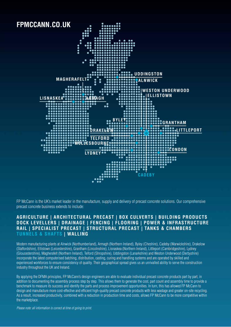
FP McCann is the UK’s market leader in the manufacture, supply and delivery of precast concrete solutions. Our comprehensive precast concrete business extends to include:
AgRICULTURE | ARCHITECTURAL PRECAST | bOx CULvERTS | bUILdINg PROdUCTS dOCK LEvELLERS | dRAINAgE | FENCINg | FLOORINg | POwER & INFRASTRUCTURE RAIL | SPECIALIST PRECAST | STRUCTURAL PRECAST | TANKS & CHAMbERS TUNNELS & SHAFTS | wALLINg
Modern manufacturing plants at Alnwick (Northumberland), Armagh (Northern Ireland), Byley (Cheshire), Cadeby (Warwickshire), Drakelow (Staffordshire), Ellistown (Leicestershire), Grantham (Lincolnshire), Lisnaskea (Northern Ireland), Littleport (Cambridgeshire), Lydney (Gloucestershire), Magherafelt (Northern Ireland), Telford (Shropshire), Uddingston (Lanarkshire) and Weston Underwood (Derbyshire) incorporate the latest computerised batching, distribution, casting, curing and handling systems and are operated by skilled and experienced workforces to ensure consistency of quality. Their geographical spread gives us an unrivalled ability to serve the construction industry throughout the UK and Ireland.
By applying the DFMA principles, FP McCann’s design engineers are able to evaluate individual precast concrete products part by part, in addition to documenting the assembly process step by step. This allows them to generate the cost, part count and assembly time to provide a benchmark to measure its success and identify the parts and process improvement opportunities. In turn, this has allowed FP McCann to design and manufacture more cost-effective and efficient high-quality precast concrete products with less wastage and greater on-site recycling. As a result, increased productivity, combined with a reduction in production time and costs, allows FP McCann to be more competitive within the marketplace.
Please note: all information is correct at time of going to print.
wELLESbOURNELONdON
UddINgSTON
ARMAgH

smoothbore tunnel and shaft linings 4
tunnel segments 6
tunnelock 8
cover and landing slabs 9
caisson units 11
jacking pipes 13
questions and answers on jacking pipes 13
steel collar joint 14
jacking pipes 15
jacking pipe installation 17
standard interjack installation 18
jacking loads 19
The FP McCann range of tunnel and shaft products have been developed to meet the requirements of the latest industry standards, which include the British Tunnelling Society Specification and the Civil Engineering Specification for the Water Industry. Designed to facilitate the ease of construction and speed of installation, FP McCann’s tunnelling and shaft systems offer strength, stability and overall performance in all types of ground conditions. Tunnel and shaft products are manufactured in accordance with FP McCann’s Quality Management System, BSI accredited to ISO 9001.
Products manufactured include:
• Smoothbore Tunnel and Shaft Linings
• Cover and Landing Slabs
• Caisson Units
• Jacking Pipes

4 | fpmccann.co.uk/tunnels-shafts 01455 290780
SMOOTHbORETUNNEL ANd SHAFT LININgS
FP McCann has developed a comprehensive range of smoothbore shaft and tunnel linings. Each size is specifically designed to meet the tunnelling industry’s exacting and varied needs, recognising the key criteria as being strength, stability and the capability of performing in all types of ground conditions.
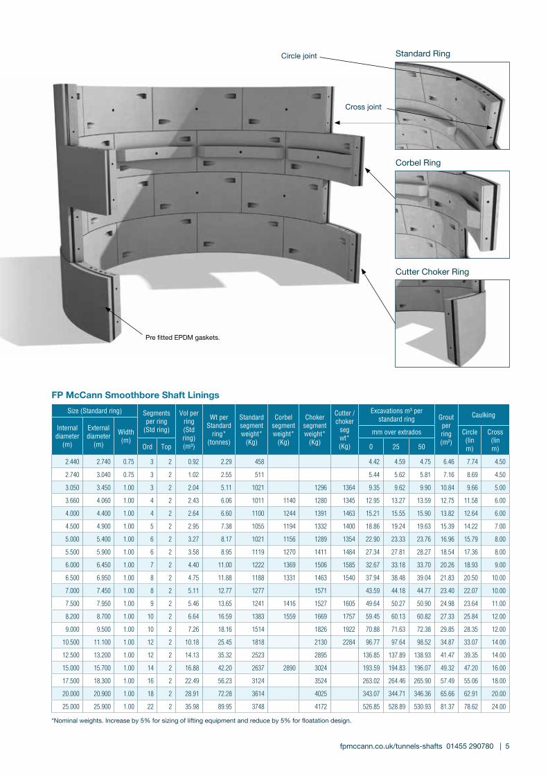
dESIgN FE AT URESAll rings, with the exception of the cutter choker, comprise of ordinary segments and two top segments. The top segments have one tapered cross joint so that they can be installed with an EPDM gasket. The cutter choker comprises all ordinary segments.
SE A LINgFP McCann is the only precast concrete manufacturer to supply pre-fitted, tailor-made EPDM rubber gaskets on the full range of smoothbore shaft and tunnel linings, except for the 2.44 and 2.74 sizes. The gaskets provide an immediate water-tight seal on construction and are fully compliant with the requirements of the British Tunnelling Society specification. Speed of build, safety and increase on-site productivity are key benefits.
CONNEC T IONCross joint connections are made using a spear bolt passing through a pocket in one segment and a plastic socket in the adjacent segment. Circle joint connections are made using a T bolt passing through a hole in one segment and into a T box in the adjacent segment. Bolts are designed to fully compress the gasket. All connections are sherardised. (Other finishes to fittings, including galvanised, are available on request). FP McCann manufactures front bolted and back bolted linings on all diameters. For diameter 10.5m and above, universal linings are available to allow for changes in construction method. (Build manual available upon request).
RINg T y PESSegmental ring types provided by FP McCann:Segmental rings in stock are front or back bolted.
1. Standard rings2. Corbel rings3. Recessed rings (standard, choker or cutter choker) 4. Choker rings 5. Combined cutter choker rings
MI x A Nd REINFORCEMEN TEach segment is wet cast to achieve a smooth internal finish. The concrete mix provides a Design Chemical Class 4 (DC4) with a minimum 28 day characteristic strength of 55 N/mm2. Alternative mixes are available. The segments are reinforced with either a reinforcing cage or structural synthetic and steel fibres to suit both design and customer requirements.
bUILd ME T HOdSThe segmental rings are suitable for underpinning, caisson and chimney construction methods.
QUA LI T y FP McCann conducts all operations using an Integrated Management System accredited to ISO 9001.
K E y FE AT URES A Nd bENEF I T S• Smooth internal faces• Simple locking process• Speedy installation• Immediate watertight seal• Cost reducing• Added safety features• Technical advice and support
fpmccann.co.uk/tunnels-shafts 01455 290780 | 5
*Nominal weights. Increase by 5% for sizing of lifting equipment and reduce by 5% for floatation design.
FP McCann Smoothbore Shaft LiningsSize (Standard ring) Segments
per ring(Std ring)
Vol perring(Std ring)(m³)
Wt per Standard
ring*(tonnes)
Standardsegmentweight*
(Kg)
Corbelsegmentweight*
(Kg)
Chokersegmentweight*
(Kg)
Cutter /choker
seg wt*(Kg)
Excavations m³ perstandard ring Grout
perring(m²)
Caulking
Internaldiameter
(m)
Externaldiameter
(m)
Width(m)
mm over extrados Circle(lin m)
Cross(lin m)Ord Top 0 25 50
2.440 2.740 0.75 3 2 0.92 2.29 458 4.42 4.59 4.75 6.46 7.74 4.50
2.740 3.040 0.75 3 2 1.02 2.55 511 5.44 5.62 5.81 7.16 8.69 4.50
3.050 3.450 1.00 3 2 2.04 5.11 1021 1296 1364 9.35 9.62 9.90 10.84 9.66 5.00
3.660 4.060 1.00 4 2 2.43 6.06 1011 1140 1280 1345 12.95 13.27 13.59 12.75 11.58 6.00
4.000 4.400 1.00 4 2 2.64 6.60 1100 1244 1391 1463 15.21 15.55 15.90 13.82 12.64 6.00
4.500 4.900 1.00 5 2 2.95 7.38 1055 1194 1332 1400 18.86 19.24 19.63 15.39 14.22 7.00
5.000 5.400 1.00 6 2 3.27 8.17 1021 1156 1289 1354 22.90 23.33 23.76 16.96 15.79 8.00
5.500 5.900 1.00 6 2 3.58 8.95 1119 1270 1411 1484 27.34 27.81 28.27 18.54 17.36 8.00
6.000 6.450 1.00 7 2 4.40 11.00 1222 1369 1506 1585 32.67 33.18 33.70 20.26 18.93 9.00
6.500 6.950 1.00 8 2 4.75 11.88 1188 1331 1463 1540 37.94 38.48 39.04 21.83 20.50 10.00
7.000 7.450 1.00 8 2 5.11 12.77 1277 1571 43.59 44.18 44.77 23.40 22.07 10.00
7.500 7.950 1.00 9 2 5.46 13.65 1241 1416 1527 1605 49.64 50.27 50.90 24.98 23.64 11.00
8.200 8.700 1.00 10 2 6.64 16.59 1383 1559 1669 1757 59.45 60.13 60.82 27.33 25.84 12.00
9.000 9.500 1.00 10 2 7.26 18.16 1514 1826 1922 70.88 71.63 72.38 29.85 28.35 12.00
10.500 11.100 1.00 12 2 10.18 25.45 1818 2130 2284 96.77 97.64 98.52 34.87 33.07 14.00
12.500 13.200 1.00 12 2 14.13 35.32 2523 2895 136.85 137.89 138.93 41.47 39.35 14.00
15.000 15.700 1.00 14 2 16.88 42.20 2637 2890 3024 193.59 194.83 196.07 49.32 47.20 16.00
17.500 18.300 1.00 16 2 22.49 56.23 3124 3524 263.02 264.46 265.90 57.49 55.06 18.00
20.000 20.900 1.00 18 2 28.91 72.28 3614 4025 343.07 344.71 346.36 65.66 62.91 20.00
25.000 25.900 1.00 22 2 35.98 89.95 3748 4172 526.85 528.89 530.93 81.37 78.62 24.00
Standard Ring
Corbel Ring
Cutter Choker Ring
Circle joint
Cross joint
Pre fitted EPDM gaskets.
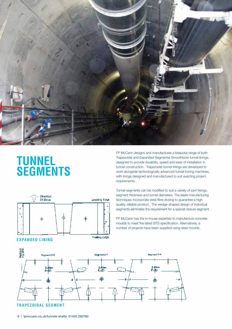
FP McCann designs and manufactures a bespoke range of both Trapezoidal and Expanded Segmental Smoothbore tunnel linings, designed to provide durability, speed and ease of installation in tunnel construction. Trapezoidal tunnel linings are developed to work alongside technologically advanced tunnel boring machines, with linings designed and manufactured to suit exacting project requirements.
Tunnel segments can be modified to suit a variety of joint fixings, segment thickness and tunnel diameters. The latest manufacturing techniques incorporate steel fibre dosing to guarantee a high quality, reliable product. The wedge-shaped design of individual segments eliminates the requirement for a special closure segment.
FP McCann has the in-house expertise to manufacture concrete moulds to meet the latest BTS specification. Alternatively, a number of projects have been supplied using steel moulds.
T R A PE zOIdA L SEgMEN T
E x PA NdEd L ININg
TUNNELSEgMENTS
6 | fpmccann.co.uk/tunnels-shafts 01455 290780
fpmccann.co.uk/tunnels-shafts 01455 290780 | 7
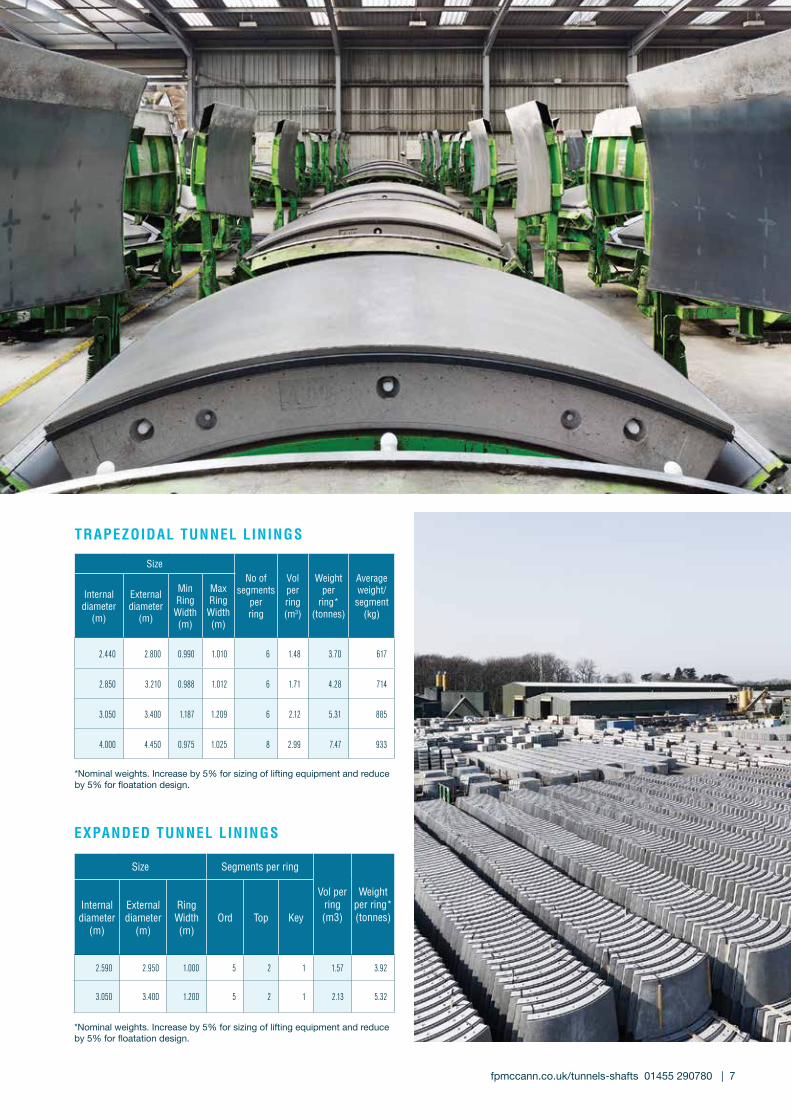
TRAPEzOIdAL TUNNEL LININgS
*Nominal weights. Increase by 5% for sizing of lifting equipment and reduce by 5% for floatation design.
*Nominal weights. Increase by 5% for sizing of lifting equipment and reduce by 5% for floatation design.
ExPANdEd TUNNEL LININgS
SizeNo of
segmentsper ring
Vol per ring (m3)
Weight per
ring*(tonnes)
Average weight/segment
(kg)
Internal diameter
(m)
External diameter
(m)
Min RingWidth(m)
Max Ring Width(m)
2.440 2.800 0.990 1.010 6 1.48 3.70 617
2.850 3.210 0.988 1.012 6 1.71 4.28 714
3.050 3.400 1.187 1.209 6 2.12 5.31 885
4.000 4.450 0.975 1.025 8 2.99 7.47 933
Size Segments per ring
Vol per ring (m3)
Weight per ring*(tonnes)
Internal diameter
(m)
External diameter
(m)
Ring Width (m)
Ord Top Key
2.590 2.950 1.000 5 2 1 1.57 3.92
3.050 3.400 1.200 5 2 1 2.13 5.32

8 | fpmccann.co.uk/tunnels-shafts 01455 290780
High strength dowel giving self alignment and good shear connection
Threaded screw connection which allows a push fit
Movable plasticanchors allow segmentto be located whenimperfectly aligned
Shield ram thrust
dESIgN
The Tunnelock circle joint connection has been developed over many years to provide the ideal connection between tunnel rings. Manufactured from a high strength durable plastic, it combines the advantages of a bolted connection with the speed, economy and alignment characteristics of a dowel. The system has been developed in conjunction with major tunnelling contractors and is suitable for use in traditional open face shields or with the latest full face tunnel boring machines. The dowels allow a very fast ring erection sequence and are designed to reduce lipping between segments. The secure interlocking system is tolerant of a dirty environment and allows for the initial misalignment of segments to compensate for tapered joints and gaskets, thus it is suitable for use with all types of tunnel rings and, in particular, with the trapezoidal segment rings. It has been used in some of the worst soft ground tunnelling conditions in the U.K. Technical data is available upon request.
Combining the advantages of a solid dowel and a secure threaded connection, this self-locking plastic connector provides a superb circle joint fixing for tunnel linings. Suitable for use with packings, hydrophilic seals and EPDM compression gaskets, it is fast and easy to build and has no pockets/recesses to fill.
MAjOR AdvANTAgES
• Highly durable connection with no corrodible parts
• Fast ring construction
• Minimum building clearance (50mm standard, 75mm heavy duty) allows the use with most types of tunnelling machine and ram length
• The rigid dowel action of the coupler re-aligns the segment and minimises the stepping of joints
• No extra reinforcement required
• Suitable for trapezoidal segment rings
• Simple and easy to use
• Does not induce bursting forces in the concrete
• No circle joint pockets to fill
• Suitable for use with all types of sealing system, including EPDM compression gaskets and hydrophilic seals
• Self-locking
• Self-aligning
TUNNELOCKPlastic tunnel lining connection

fpmccann.co.uk/specialist 01353 861416 | 9
COv ER A Nd L A NdINg SL A bSReinforced cover and landing slabs are an integral part of FP McCann’s tunnels and shafts product range, manufactured at the company’s specialist precast concrete facility. Both cover and landing slabs are cast to design specifications and made to order for just-in-time delivery. On site, the slabs can be quickly installed and provide an integral secure shaft cover or internal landing.
SIzESCover and landing slabs are generally circular to match the FP McCann range of smoothbore shaft segments and other segmental linings. They are available in 1, 2, 3 and 4+ sections. The standard range is highlighted opposite. A bespoke design facility is available for non-standard shapes and sizes.
One piece Cover Slabs
Shaft internaldiameter (mm)
Shaft externaldiameter (mm)
Slab thickness (mm)
Total slab weight (T)
2100 2350 250 2.82
2400 2680 275 4.03
2700 3000 275 5.05
3000 3360 300 6.92
Two piece Cover Slabs
Shaft internaldiameter (mm)
Shaft externaldiameter (mm)
Slab thickness (mm)
Total slab weight (T)
3000 3360 300 6.92
3660 4060 300/325 9.84/11.27
4000 4400 350 13.84
4500 4900 375 18.39
5000 5400 400 23.82
Three piece Cover Slabs
Shaft internaldiameter (mm)
Shaft externaldiameter (mm)
Slab thickness (mm)
Total slab weight (T)
5000 5400 400 23.82
5500 5900 425 30.21
Four + piece Cover Slabs
Shaft internaldiameter (mm)
Shaft externaldiameter (mm)
Slab thickness (mm)
Total slab weight (T)
5500 5900 425 30.21
6000 6450 450 38.23
6500 6950 475 46.85
7500 7950 525 67.76
8000 8500 550 81.15
9000 9500 600 110.58
10500 11100 675 169.83
12500 13200 775 275.75

10 | fpmccann.co.uk/tunnels-shafts 01455 290780
MI x A Nd REINFORCEMEN TSlab sections are wet cast in fabricated steel moulds and are steel cage reinforced. The concrete mix design is to a standard characteristic strength of 55N/mm2 at 28 days. Alternative mixes are available.
dESIgN FE AT URESDesign and detailing may be undertaken by FP McCann or to our customers’ design specification. Reinforced cover slabs are generally designed to withstand loads in accordance with the recommendations of relevant British Standards (e.g. BS EN 1990 and BD37/01, usually adopting 30HB loading or Eurocodes with appropriate load models, in conjunction with relevant overburden). Landing slabs are designed for an imposed loading of 5kN/m2.
L IF T INg A Nd H A NdLINgDepending on lifting requirements on site, FP McCann is able to supply fitted lifting loops or cast-in sockets and spherical head lifting anchors.
QUA LI T y STA NdA RdSShaft cover slabs and landing slabs are manufactured in accordance with FP McCann’s quality management system, BSI accredited to ISO 9001.
K E y FE AT URES A Nd bENEF I T S• No formwork or ready mixed concrete required• Simple jointing system• Speedy installation• Bespoke design and casting service• Technical advice and support
COvER &LANdINg SLAbS
Cover Slabs with RC Beams
Shaft internaldiameter (mm)
Shaft externaldiameter (mm)
Slab thickness (mm)
Number ofRC beams
8000 8500 250 2
9000 9500 250 2
10500 11100 275 2
12500 13200 350 to 250 2, 3 or 4
15000 15700 400 to 300 2, 3 or 4
Cover Slabs with RC Beam or Pre-stressed Beams
Shaft internaldiameter (mm)
Shaft externaldiameter (mm)
Slab thickness (mm)
Number ofRC beams
20000 20900 Special Special
25000 25900 Special Special
One piece Landing Slabs
Shaft internaldiameter (mm)
Slabdiameter (mm)
Slab thickness (mm)
Total slabweight (T)
2100 2050 175 1.50
2400 2350 175 1.97
2700 2650 200 2.87
3000 2950 200 3.55
Two piece Landing Slabs
Shaft internaldiameter (mm)
Slabdiameter (mm)
Slab thickness (mm)
Total slabweight (T)
3000 2950 200 3.55
3660 3610 225 5.99
4000 3950 250 7.97
4500 4450 275 11.12
5000 4950 300 15.01
5500 5450 325 19.71
6000 5950 350 25.30
Three + piece Landing Slabs
Shaft internaldiameter (mm)
Slabdiameter (mm)
Slab thickness (mm)
Total slabweight (T)
6000 5950 350 25.30
6500 6450 375 31.86
7500 7450 425 48.17
8000 7950 450 58.08
9000 8950 500 81.79

Caissons Shafts
DN
Cutting Shoe Weight (Kg)
Approx. Weight p/metre Caisson
(with cutting shoe) (Kg)**
Approx. Weight p/metre Caisson (without cutting shoe)**
mm 10mm 20mm 10mm 20mm Kg
2100 320 581 2590 2851 2270
2400 378 635 3278 3535 2900
2700 441 794 3931 4284 3490
3000 529 953 5209 5633 4680
3600 641 1148 6361 6868 5720
4000* 725 1298 7585 8158 6860
FP MCCANN CAISSON RANgE FP McCann manufactures a range of reinforcing units suitable for sinking by the caisson method. Caisson shaft units can be supplied with diameters of 2100mm up to 4000mm. Caissons are manufactured within the scope of the ISO9001 accredited Quality Management System and in accordance with BS EN 1917 and BS5911-3, where appropriate^.
However, 3600mm and 4000mm diameters remain operative within the scope of the ISO 9001 accredited Quality Management System.
Open caisson-sinking techniques permit a shaft structure to be progressively sunk, either under its own weight or with the aid of caisson jacks, in a controlled manner from the surface to a predetermined depth. Caisson shafts are constructed using a metal cutter ring and base section with rings being added on top as excavation proceeds. The technique is suited to shaft construction through weak soils, high-plasticity clays, silts, sands and gravel, particularly below the water table.
CAISSON UNITS
* DN4000 supplied as a two piece unit. ** Nominal weights increase by 5% for sizing lifting equipment and reduce by 5% for floatation design.
Base units may be fitted with a light duty (10mm) or a medium duty (20mm) cutting shoe.
CAISSON RINgS - TAbLE OF wEIgHTS (dN 2100-4000)
fpmccann.co.uk/tunnels-shafts 01455 290780 | 11
^ Caisson manholes cannot be CE marked as their diameters are not covered by the scope of the harmonised European Standard BS EN 1917. However, 2100mm - 3000mm manholes are kite-marked against the scope of the complimentary British Standard BS5911-3.
Caissons Shafts DN Available Depths (mm) Barrel DNWall
ThicknessLifting (Cast in Socket)
mm 1000 750 500 mm mm Qty per unit
2100 P P P 2350 125 3 No. RD24 Wavy Tail Inserts
2400 P P P 2680 140 3 No. RD24 Wavy Tail Inserts
2700 P P P 3000 150 3 No. RD30 Wavy Tail Inserts
3000 P P P 3360 180 3 No. RD30 Wavy Tail Inserts
3600 P P P 3970 185 3 No. RD30 Wavy Tail Inserts
4000* P P O 4400 200 6 No. RD36 Wavy Tail Inserts
*DN4000 supplied as a two piece unit.

12 | fpmccann.co.uk/jacking-pipes 01455 290780
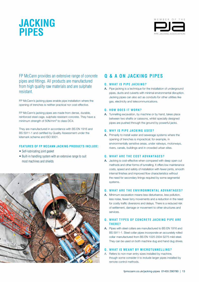
Q & A ON jACKINg PIPES
Q. w H AT IS P IP E j ACK INg ?A. Pipe jacking is a technique for the installation of underground pipes, ducts and culverts with minimal environmental disruption. Jacking pipes can also act as conduits for other utilities like gas, electricity and telecommunications.
Q. HOw dOE S I T wORK?A. Tunnelling excavation, by machine or by hand, takes place between two shafts or caissons, whilst specially designed pipes are pushed through the ground by powerful jacks.
Q. w H y IS P IP E j ACK INg USEd ?A. Primarily to install water and sewerage systems where the opening of trenches is impractical; for example, in environmentally sensitive areas, under railways, motorways, rivers, canals, buildings and in crowded urban sites.
Q. w H AT A RE T HE COS T A dvA N TAgE S ?A. Jacking is cost-effective when compared with deep open cut methods and other forms of tunnelling. It offers low maintenance costs, speed and safety of installation with fewer joints, smooth internal finishes and improved flow characteristics without the need for secondary linings required by some segmental systems.
Q. w H AT A RE T HE EN v IRONMEN TA L A dvA N TAgE S ?A. Minimum excavation means less disturbance, less pollution, less noise, fewer lorry movements and a reduction in the need for costly traffic diversions and delays. There is a reduced risk of settlement, damage or movement to other structures and services.
Q. w H AT T y P E S OF CONCRE T E j ACK INg P IP E A RE T HERE ?A. Pipes with steel collars are manufactured to BS EN 1916 and BS 5911-1. Steel collar pipes incorporate an accurately rolled collar manufactured from BS EN 1025 2004 S275 mild steel. They can be used on both machine dug and hand dug drives.
Q. w H AT IS ME A N T by MICRO T UNNELL INg ?A. Refers to non-man entry sizes installed by machine, though some consider it to include larger pipes installed by remote control methods.
fpmccann.co.uk/jacking-pipes 01455 290780 | 13
jACKINg PIPES
FP McCann provides an extensive range of concrete pipes and fittings. All products are manufactured from high quality raw materials and are sulphate resistant.
FP McCann’s jacking pipes enable pipe installation where the opening of trenches is neither practical nor cost-effective.
FP McCann’s jacking pipes are made from dense, durable, reinforced steel cage, sulphate resistant concrete. They have a minimum strength of 50N/mm2 to class DC4.
They are manufactured in accordance with BS EN 1916 and BS 5911-1 and certified by Quality Assessment under the kitemark scheme and ISO 9001.
FEATURES OF FP MCCANN jACKINg PROdUCTS INCLUdE:
• Self-lubricating joint gasket• Built-in handling system with an extensive range to suit most machines and shields

14 | fpmccann.co.uk/jacking-pipes 01455 290780
STEEL COLLAR jOINT
MDF PackEr
StEEl collar
HyDroPHilic SEal
laMEll gaSkEt E
DA
BC
F
Alternative Length of Pipes (Maximum length 2.5m)Alternative length of pipes in some of the sizes shown above can be manufactured to order.FP McCann is always interested in adding to the above range, and would be pleased to discuss the supply of any sizes not shown.
* Nominal size as given by Table 6 BS 5911-1.# These items are not covered by BS EN 1916 and BS 5911-1 but have been designed and tested using the same criteria. Weights given are the nominal weights increased by 5% to allow for variations in material unit tolerance
jACKINg PIPES
DN* (mm)
Bore Diameter A
(mm)
Wall Thickness B
(mm)
Outside DiameterC (mm)
Length Metres
Weight KgApprox
Spigot LengthD (mm)
Socket LengthE (mm)
Packer Size
Width (mm)
Packer SizeThickness
(mm)
Int.Dia to Packer F (mm)
Proof Load kN/m
Maximun Load KN/m
# 450 450 77 604 1.20 430 115 110 33 12 480 36 # 54
# 600 585 90 764 1.20 640 125 110 46 15 611 48 # 72
# 600 585 90 764 2.00 1050 125 110 46 15 611 48 # 72
900 904 98 1100 2.50 2120 130 125 56 15 934 72 108
1000 980 110 1200 2.50 2580 130 125 66 15 1010 72 120
1200 1200 115 1430 1.20 1590 130 125 68 18 1230 96 144
1200 1200 115 1430 2.50 3250 130 125 68 18 1230 96 144
1400 1350 125 1600 2.50 3950 130 125 78 18 1380 112 168
1500 1500 140 1780 2.50 4910 130 125 93 18 1530 120 180
1800 1830 155 2140 2.47 6490 134 125 110 18 1860 145 216
2000 1950 190 2330 2.35 8150 134 125 145 18 1980 160 240
2000 1950 190 2330 2.50 8600 134 125 145 18 1980 160 240
2000 1980 175 2330 2.50 8040 134 125 130 18 2010 160 240
2000 2076 167 2410 2.47 7900 134 125 122 18 2106 160 240
2400 2425 200 2825 2.50 11190 145 140 150 18 2455 200 300
FP MCCANN jACKINg PIPE RANgE

LE A d P IPESLead pipes are located at the front of the drive. It is standard practice to fit a steel shield over the lead pipe in every hand dug drive, providing protection to miners and facilitating steering. Machine dug drives do not usually require a lead pipe as the contractor can adapt the machine to fit over a standard pipe spigot.
SPECI A L CH A R AC T ERIST ICS• A flat end instead of a spigot - 600mm long by 20mm deep rebate• Joint gaskets are not supplied as standard with lead
gROU T SOCK E T S OR LUbRICAT ION HOLESDesigned to reduce friction during jacking, lubricating or grout sockets can be cast into standard pipes to suit customer requirements. They are normally 1 1/4”BSP steel sockets fitted with plugs. Conical non-return valves are supplied as standard. The ratio of pipes with grout sockets to standard pipes varies, depending on ground conditions. As a guide, it can be one pipe in every three, or one in every five.
TA bLE SHOwINg STA NdA Rd CONFIgUR AT IONS OF gROU T SOCK E T S.
LEAd PIPE
Pipe Diameter mm
3 holes per pipe
1950 - 2400
2 holes per pipe
900-1800
LocationNumber
TyPICAL INTERjACK STATION
Trail Pipe Packer PackerThrust Rings lead Pipe
Jacks
INTERjACK TRAIL PIPE
PACK ERSIt is important that suitable packing material be used between adjacent pipes, to ensure even stress distribution and load transfer. We recommend medium density fibre board (MDF). FP
McCann can supply and fix packers at works, although the con-tractor usually supplies and fixes them on site prior to pipe instal-lation. It is important that packers are fitted in the correct position.
INTERMEdIATE jACKINg STATIONS (INTERjACKS)lnterjacks are frequently installed on drives where the jacking forces required exceed the capability of the pipe or the jacks. Install-ing interjacks relieves pressure on the whole drive length by first pushing the section of pipes in front of the interjack using jacks installed within the interjack itself; the rear section of pipes is then pushed by the main jacks. Each interjack station comprises two pipes, a lead and a trail, with a steel can or shield which is either cast integrally with the lead pipe - a fixed can, or fitted round the pipe separately - a loose can. The interjack trail pipe is common to both fixed and loose can types. The choice of interjack type is usually left to the contractor’s preference.
F I x Ed CA N IN T ER jACKSThese are used with steel collar pipes. FP McCann provides the lead pipe with the can already fitted. It then becomes the contractor’s responsibility to fit suitable steel thrust rings, packers and jacks inside the can.
LOOSE CA N IN T ER jACKSGenerally used with in-wall jointed pipes and have a lead pipe with a short 300mm by 20mm recess in place of the socket. The contractor provides the can as well as the thrust rings, packers and jacks.
IN T ER jACK T R A IL P IPESRecognisable by their long 1400mm by 20mm rebate instead of the normal spigot. Two recesses are located towards the end of the rebate to take special sealing rings provided by FP McCann. Lubrication points are positioned between the recesses.
fpmccann.co.uk/jacking-pipes 01455 290780 | 15
16 | fpmccann.co.uk/ jacking-pipes 01455 290780
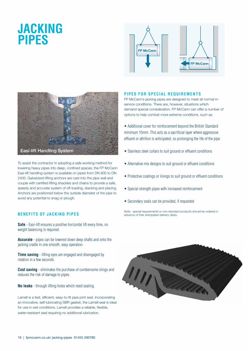
Easi-lift Handling System
To assist the contractor in adopting a safe working method for lowering heavy pipes into deep, con fined spaces, the FP McCann Easi-lift handling system is available on pipes from DN 900 to DN 2400. Galvanized lifting anchors are cast into the pipe wall and couple with certified lifting shackles and chains to provide a safe, speedy and accurate sys tem of off-loading, stacking and placing. Anchors are positioned below the outside diameter of the pipe to avoid any potential to snag or plough.
bENEF I T S OF jACK INg P IPES
Safe - Easi-lift ensures a positive horizontal lift every time, no weight balancing is required.
Accurate - pipes can be lowered down deep shafts and onto the jacking cradle in one smooth, easy operation.
Time saving - lifting eyes are engaged and disengaged by rotation in a few seconds.
Cost saving - eliminates the purchase of cumbersome slings and reduces the risk of damage to pipes.
No leaks - through lifting holes which need sealing.
Lamell is a fast, efficient, easy-to-fit pipe joint seal. Incorporating an innovative, self-lubricating SBR gasket, the Lamell seal is ideal for use in wet condi tions. Lamell provides a reliable, flexible, water-resistant seal requiring no additional lubrication.
FP McCann
FP McCann
PIPES FOR SPECI A L REQUIREMEN T SFP McCann’s jacking pipes are designed to meet all normal in-service conditions. There are, however, situations which demand special consideration. FP McCann can offer a number of options to help combat more extreme conditions, such as:
• Additional cover for reinforcement beyond the British Standard minimum 15mm. This acts as a sacrificial layer where aggressive effluent or attrition is anticipated, so prolong ing the life of the pipe
• Stainless steel collars to suit ground or effluent conditions
• Alternative mix designs to suit ground or effluent conditions
• Protective coatings or linings to suit ground or effluent conditions
• Special strength pipes with increased reinforcement
• Secondary seals can be provided, if requested
Note: special requirements or non-standard products should be ordered in advance of their anticipated delivery dates.
jACKINg PIPES
jACKINg PIPEINSTALLATION
H A NdLINg A Nd jOIN T INg - gENER A LFP McCann’s jacking pipes are robust and should arrive on site in good condition. Care in handling is simply a matter of common sense.
dO TA K E E x T R A CA RE wI T H T HE jOIN T SLifting appliances should be capable of smooth hoisting, lowering and travelling with the heaviest pipe, and must satisfy the required safety regulations.
E ASI -L IF T H A NdLINg SyST EMThis is the simplest, safest and most efficient way of handling FP McCann’s jacking pipes, DN 900 and above. Place the lifting eyes over the cast-in anchors and rotate, ensuring the lugs on each eye are pointing towards the centre of the pipe before commencing the lift.
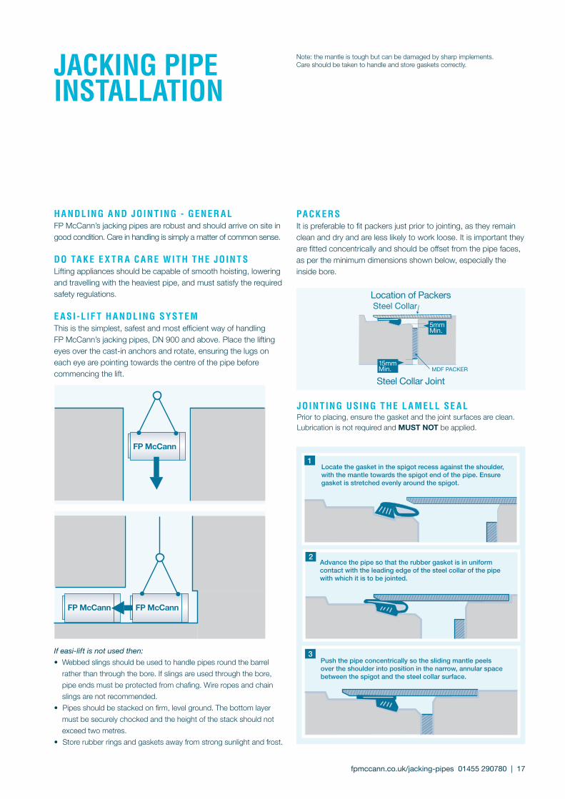
PACK ERSIt is preferable to fit packers just prior to jointing, as they remain clean and dry and are less likely to work loose. It is important they are fitted concentrically and should be offset from the pipe faces, as per the minimum dimensions shown below, especially the inside bore.
jOIN T INg USINg T HE L A MELL SE A LPrior to placing, ensure the gasket and the joint surfaces are clean. Lubrication is not required and MUST NOT be applied.
Note: the mantle is tough but can be damaged by sharp implements. Care should be taken to handle and store gaskets correctly.
If easi-lift is not used then:• Webbed slings should be used to handle pipes round the barrel rather than through the bore. If slings are used through the bore, pipe ends must be protected from chafing. Wire ropes and chain slings are not recommended.• Pipes should be stacked on firm, level ground. The bottom layer must be securely chocked and the height of the stack should not exceed two metres.• Store rubber rings and gaskets away from strong sunlight and frost.
FP McCann
FP McCannFP McCann
Locate the gasket in the spigot recess against the shoulder, with the mantle towards the spigot end of the pipe. Ensure gasket is stretched evenly around the spigot.
Advance the pipe so that the rubber gasket is in uniform contact with the leading edge of the steel collar of the pipe with which it is to be jointed.
Push the pipe concentrically so the sliding mantle peels over the shoulder into position in the narrow, annular space between the spigot and the steel collar surface.
3
2
1
fpmccann.co.uk/jacking-pipes 01455 290780 | 17
18 | fpmccann.co.uk/jacking-pipes 01455 290780
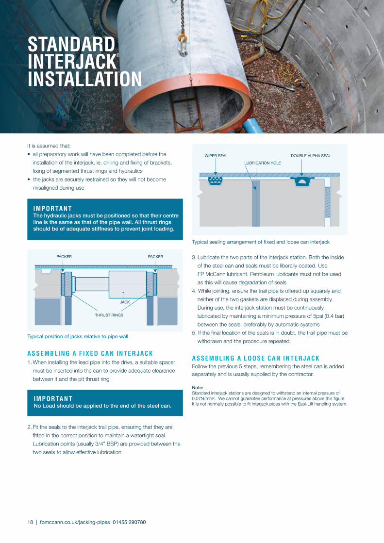
STANdARd INTERjACKINSTALLATION
It is assumed that:• all preparatory work will have been completed before the installation of the interjack, ie. drilling and fixing of brackets, fixing of segmented thrust rings and hydraulics• the jacks are securely restrained so they will not become misaligned during use
ASSEMbLINg A F I x Ed CA N IN T ER jACK1. When installing the lead pipe into the drive, a suitable spacer must be inserted into the can to provide adequate clearance between it and the pit thrust ring
2. Fit the seals to the interjack trail pipe, ensuring that they are fitted in the correct position to maintain a watertight seal. Lubrication points (usually 3/4” BSP) are provided between the two seals to allow effective lubrication
3. Lubricate the two parts of the interjack station. Both the inside of the steel can and seals must be liberally coated. Use FP McCann lubricant. Petroleum lubricants must not be used as this will cause degradation of seals4. While jointing, ensure the trail pipe is offered up squarely and neither of the two gaskets are displaced during assembly. During use, the interjack station must be continuously lubricated by maintaining a minimum pressure of 5psi (0.4 bar) between the seals, preferably by automatic systems5. If the final location of the seals is in doubt, the trail pipe must be withdrawn and the procedure repeated.
ASSEMbLINg A LOOSE CA N IN T ER jACKFollow the previous 5 steps, remembering the steel can is added separately and is usually supplied by the contractor.
Note: Standard interjack stations are designed to withstand an internal pressure of 0.07N/mm2. We cannot guarantee performance at pressures above this figure. It is not normally possible to fit lnterjack pipes with the Easi-Lift handling system.
Typical position of jacks relative to pipe wall
Typical sealing arrangement of fixed and loose can interjack
IMPORTA N TNo Load should be applied to the end of the steel can.
tHruSt riNgS
JACk
PackEr PackEr
IMPORTA N TThe hydraulic jacks must be positioned so that their centre line is the same as that of the pipe wall. All thrust rings should be of adequate stiffness to prevent joint loading.
lubricatioN HolE
WiPEr SEal DoublE alPHa SEal

FP McCann’s jacking pipes are designed to meet the requirements of British Standard 5911 Part 1 and European Standard BS EN 1916. The Maximum Jacking Force (Fjmax*) which can be applied to a pipe is determined by the pipe strength, the configuration of the thrust ring and the tunnel alignment, i.e. the angular deflec-tion between pipes. The maximum load decreases as angular deflections occur during jacking. Should deflection exceed that which can be accommodated by the packer, the maximum load decreases significantly. The figures opposite are for guidance only. For further assistance, contact FP McCann’s technical department.
* It is important to note that the table indicates the loads for which each pipe was designed and does not include any safety factor used by the contractor (Refer to clause 5.3.4 BS EN 1916)
fpmccann.co.uk/jacking-pipes 01455 290780 | 19
jACKINg LOAdS
Angular Deflection
Pipe Nominal
Size mm
Pipe I/D mm
Pipe O/D mm
Packer Depth mm
Packer Thickness
(mm) 0**
Angle Varies
***0.25 0.5 1.0
degrees degrees degrees degrees
450 450 604 33 12 111 56 56 56 35
600 585 764 46 15 200 100 100 86 52
900 904 1100 56 15 365 183 183 117 73
1000 980 1200 66 15 468 234 234 141 86
1200 1200 1430 68 18 581 291 252 156 95
1350 1350 1600 78 18 749 375 298 186 112
1500 1500 1780 93 18 994 497 365 227 134
1800 1830 2140 110 18 1427 714 461 287 166
1950 1950 2330 145 18 2029 1015 612 373 203
1980 1980 2330 130 18 1832 916 556 343 192
2100 2076 2410 122 18 1790 895 534 332 188
2400 2425 2825 150 18 2573 1287 687 419 225
** The load must be perpendicular to the joint face (no deflection and all jacking forces perfectly square) *** There is anqular deflection but there is no joint gap i.e. any deflection being taken up within the packer
H AUL AgE LOA d QUA N T I T IES Table showing quantities per 24.5 tonne load
M A x IMUM dESIgN LOA dS - ( TONNES)
In-wall joint 2.5m long Steel Collar joint 2.5m long
Approx. number of Approx. number of Approx. number of
Nominal Dia. mm pipes metres Nominal
Dia. mm pipes metres Nominal Dia. mm pipes metres
900 8 20.0 900 11 27.5 1950 3 7.50
1050 6 15.0 1000 9 22.5 2100 3 7.50
1200 5 12.5 1200 7 17.5 2400 2 5.00
1500 4 10.0 1350 6 15.0 Microtunnelling pipes 2m long
1800 3 7.50 1500 5 12.5 600 24 48.0
2000 2 5.00 1650 4 10.0 675 21 42.0
2400 2 5.00 1800 3 7.50 Microtunnelling pipes 1.2m long
1.2m long 1.2m long 450 60 72.0
900 17 20.4 1200 15 18.0 600 40 48.0
FPMCCANN.CO.UK
AgRICULTURELydney 01594 847500 Magherafelt 028 7954 9026
ARCHITECTURAL PRECASTLondon 020 3905 7640
bUILdINg PROdUCTSLisnaskea 028 6772 1286
bOx CULvERTSWeston Underwood 01335 361269
dRAINAgE Ellistown 01530 240000 Magherafelt 028 7954 9026
dOCK LEvELLERS Weston Underwood 01335 361269
FENCINgCadeby 01455 290780
FLOORINg Weston Underwood 01335 361269Uddingston 01698 803300
POwER ANd INFRASTRUCTURE Cadeby 01455 290780
RAIL Cadeby 01455 290780
SPECIALIST PRECAST Littleport 01353 861416
STRUCTURAL PRECASTByley 01606 843500
TANKS ANd CHAMbERSWellesbourne 01789 336960
TUNNELS ANd SHAFTS Cadeby 01455 290780
wALLINg Lydney 01594 847500
CAdEbyBrascote Lane Nuneaton Cadeby WarwickshireCV13 0BBT 01455 290780 [email protected]