Embed Size (px)
Citation preview
Pre-touch Sensing for Sequential Manipulation
Boling Yang1 Patrick Lancaster2 Joshua R. Smith3
Abstract— The primary focus of this work is to examinehow robots can achieve more robust sequential manipulationthrough the use of pre-touch sensors. The utility of close-rangeproximity sensing is evaluated through a robotic system thatuses a new optical time-of-flight pre-touch sensor to completea highly precise and sequential task - solving the Rubik’s cube.The techniques used in this task are then extended to a moregeneral framework in which ICP is used to match pre-touchdata to a reference model, demonstrating that even simple pre-touch scans can be used to recover the pose of common objectsthat require sequential manipulation.
I. INTRODUCTION
As robots continue to transition from operating in con-trolled, carefully designed environments towards human-centric, unstructured ones, they will have to make moresophisticated use of sensing to cope with the inherentuncertainty in our real world. In particular, robust robotmanipulation is difficult to achieve because of the uncertaintyinvolved in manipulating an object [1]. For tasks that requiresequential manipulations, the robot’s belief about the poseof the object at any point in time can be corrupted bya poor characterization of the initial pose, or through theaccumulation of error caused by controller noise, previousimperfect manipulations, and perceptual errors. Dependingon the precision required, such errors can cause the robot tofail at the task of interest.
In this work, we show that accumulating manipulationerrors can be controlled by proximity sensors mounted tothe robot’s end-effectors, what we call ’pre-touch’ sensors.First, we demonstrate that pre-touch sensing allows a robotto much more effectively complete a particular sequentialmanipulation task, i.e solving a Rubik’s cube. In order todemonstrate that pre-touch sensing can be applied to otherobjects that may require sequential manipulation, we showthat employing even a simple pre-touch scanning strategyallows the robot to infer the pose of a number of commonobjects.
We chose to first tackle the task of solving the Rubik’scube because the challenges that general purpose robots facewhen attempting to achieve sequential manipulation are wellrepresented by this task. Solving a Rubik’s cube can require
This work was supported in part by the National Science Foundationunder grant IIS-1427419
1 Boling Yang is with the Department of Electrical Engineering, Univer-sity of Washington, Seattle, WA 98195, USA [email protected]
2 Patrick Lancaster is with the Department of Computer Scienceand Engineering, University of Washington, Seattle, WA 98195, [email protected]
3 Joshua R. Smith is with the Department of Computer Science andEngineering and the Department of Electrical Engineering, University ofWashington, Seattle, WA 98195, USA [email protected]
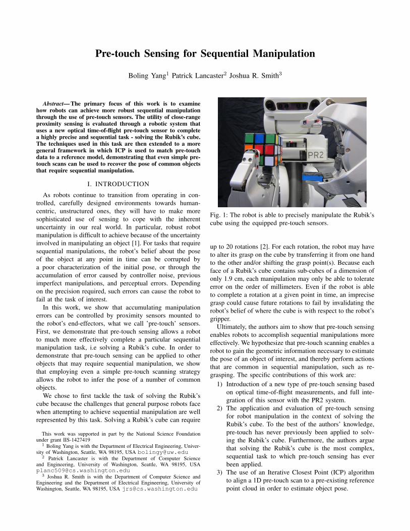
Fig. 1: The robot is able to precisely manipulate the Rubik’scube using the equipped pre-touch sensors.
up to 20 rotations [2]. For each rotation, the robot may haveto alter its grasp on the cube by transferring it from one handto the other and/or shifting the grasp point(s). Because eachface of a Rubik’s cube contains sub-cubes of a dimension ofonly 1.9 cm, each manipulation may only be able to tolerateerror on the order of millimeters. Even if the robot is ableto complete a rotation at a given point in time, an imprecisegrasp could cause future rotations to fail by invalidating therobot’s belief of where the cube is with respect to the robot’sgripper.
Ultimately, the authors aim to show that pre-touch sensingenables robots to accomplish sequential manipulations moreeffectively. We hypothesize that pre-touch scanning enables arobot to gain the geometric information necessary to estimatethe pose of an object of interest, and thereby perform actionsthat are common in sequential manipulation, such as re-grasping. The specific contributions of this work are:
1) Introduction of a new type of pre-touch sensing basedon optical time-of-flight measurements, and full inte-gration of this sensor with the PR2 system.
2) The application and evaluation of pre-touch sensingfor robot manipulation in the context of solving theRubik’s cube. To the best of the authors’ knowledge,pre-touch has never previously been applied to solv-ing the Rubik’s cube. Furthermore, the authors arguethat solving the Rubik’s cube is the most complex,sequential task to which pre-touch sensing has everbeen applied.
3) The use of an Iterative Closest Point (ICP) algorithmto align a 1D pre-touch scan to a pre-existing referencepoint cloud in order to estimate object pose.
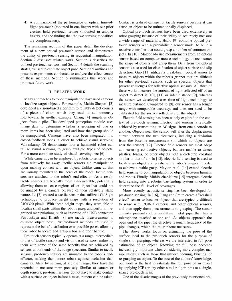
4) A comparison of the performance of optical time-of-flight pre-touch (mounted in one finger) with our priorelectric field pre-touch sensor (mounted in anotherfinger), and the finding that the two sensing modalitiesare complementary.
The remaining sections of this paper detail the develop-ment of a new optical pre-touch sensor, and demonstratethe utility of pre-touch sensing in sequential manipulation.Section 2 discusses related work. Section 3 describes theutilized pre-touch sensors, and Section 4 details the scanningstrategies used to estimate object pose. Section 5 outlines andpresents experiments conducted to analyze the effectivenessof these methods. Section 6 summarizes this work andproposes future work.
II. RELATED WORK
Many approaches to robot manipulation have used camerasto localize target objects. For example, Maitin-Shepard [3]developed a vision-based algorithm to reliably detect cornersof a piece of cloth, which they used to autonomouslyfold towels. In another example, Chang [4] singulates ob-jects from a pile. The developed perception module usesimage data to determine whether a grouping of one ormore items has been singulated and how that group shouldbe manipulated. Cameras have also been integrated intoclosed-feedback loops in order to achieve visual servoing.Vahrenkamp [5] demonstrate how a humanoid robot canutilize visual servoing to grasp multiple types of objects.For a more complete study of visual servoing, see [6].
While cameras can be employed by robots to sense objectsfrom relatively far away, tactile sensors aid manipulationupon making contact with an object. Unlike cameras thatare usually mounted to the head of the robot, tactile sen-sors are attached to the robot’s end-effector. As a result,tactile sensors are typically more maneuverable, potentiallyallowing them to sense regions of an object that could notbe imaged by a camera because of their relatively staticnature. Li [7] created a tactile sensor that utilized GelSighttechnology to produce height maps with a resolution of240x320 pixels. With these height maps, they were able tolocalize small parts within the robot’s grasp and perform fine-grained manipulations, such as insertion of a USB connector.Petrovskaya and Khatib [8] use tactile measurements toestimate object pose. Particle-based methods are used torepresent the belief distribution over possible poses, allowingtheir robot to locate and grasp a box and door handle.
Pre-touch sensors typically operate at a range intermediateto that of tactile sensors and vision-based sensors, endowingthem with some of the same benefits that are achieved bysensors at both ends of the range spectrum. Similar to tactilesensors, pre-touch sensors are mounted to the robot’s end-effector, making them more robust against occlusion thancameras. Also, by sensing at a closer range, they have thepotential to measure more precisely. Similar to camera ordepth sensors, pre-touch sensors do not have to make contactwith a surface or object before a measurement can be taken.
Contact is a disadvantage for tactile sensors because it cancause an object to be unintentionally displaced.
Optical pre-touch sensors have been used extensively inrobot grasping because of their ability to accurately measurea wide range of materials. Hsaio [9] combine optical pre-touch sensors with a probabilistic sensor model to build areactive controller that could grasp a number of common ob-jects. In [10], Maldonado use measurements from an opticalsensor based on computer mouse technology to reconstructthe shape of objects and grasp them. Data from the opticalsensor is also used for classification of object surface and slipdetection. Guo [11] utilizes a break-beam optical sensor tomeasure objects within the robot’s gripper that are difficultfor other pre-touch sensors, such as specular objects thatpresent challenges for reflective optical sensors. All three ofthese works measure the amount of light reflected off of anobject to detect it [10], [11] or infer distance [9], whereasthe sensor we developed uses time-of-flight technology tomeasure distance. Compared to [9], our sensor has a longerrange with comparable accuracy, and does not need to becalibrated for the surface reflectivity of the object.
Electric field sensing has been widely explored in the con-text of pre-touch sensing. Electric field sensing is typicallyachieved by transmitting an AC signal from one electrode toanother. Objects near the sensor will alter the displacementcurrent between the two electrodes, inducing a deviationfrom the baseline measurement (in which no objects arenear the sensor) [12]. Electric field sensors are most adeptat measuring conductive objects, but are unable to detectplastics, foams, or other objects with a dielectric constantsimilar to that of air. In [13], electric field sensing is used tolocalize an object and preshape the robot’s fingers in orderto achieve a stable grasp. Mayton et al. [14] extend electricfield sensing to co-manipulation of objects between humansand robots. Finally, Muhlbacher-Karre [15] integrate electricfield sensing into a robotic bar-tending system in order todetermine the fill level of beverages.
More recently, acoustic sensing has been developed forpre-touch sensing. In [16], Jiang and Smith create a ”seashelleffect” sensor to localize objects that are typically difficultto sense with RGB-D cameras and other optical sensors,and then apply those measurements to grasping. The sensorconsists primarily of a miniature metal pipe that has amicrophone attached to one end. As objects approach theopen end of the pipe, the effective resonant frequency of thepipe changes, which the microphone measures.
The above works focus on estimating the pose of thesurface local to the pre-touch sensors for the purpose ofsingle-shot grasping, whereas we are interested in full poseestimation of an object. Knowing the full pose becomesincreasingly important when considering more complex ma-nipulations, such as those that involve opening, twisting, orre-grasping an object. To the best of the authors’ knowledge,our work is the first to estimate the full pose of an objectby applying ICP (or any other similar algorithm) to a single,sparse pre-touch scan.
One of the disadvantages of the previously mentioned pre-

10 20 30 40 50 60 70 80 90100
True Target Distance (mm)
0
10
20
30
40
50
60
70
80
90
100
110
Me
asu
red
Ta
rge
t D
ista
nce
(m
m)
White Target
10 20 30 40 50 60 70 80 90100
True Target Distance (mm)
0
10
20
30
40
50
60
70
80
90
100
110
Me
asu
red
Ta
rge
t D
ista
nce
(m
m)
Grey Target
10 20 30 40 50 60 70 80 90100
True Target Distance (mm)
0
10
20
30
40
50
60
70
80
90
100
110
Me
asu
red
Ta
rge
t D
ista
nce
(m
m)
Black Target
Fig. 2: Boxplots of sensor measurements over the specified range for white, grey, and black target objects. Each box consistsof 30 measurements.
Fig. 3: Left: The printed circuit boards that compose thesensor. Middle: The 3D printed sensor casing. The hole inthe middle of the case is for a sensing module soldered tothe bottom of the main PCB. Right: The assembled sensorwith arrows denoting the directions of five out of six sensormodules’ infrared beams.
touch sensors is that they only make sparse measurements,requiring the robot to move its end-effector in order todensely measure a region of interest prior to manipulation.Thus, a number of works have developed a compromisebetween head-mounted cameras and pre-touch sensing bymounting cameras on the robot’s wrist [17] [18]. However,although less actuation may be required to measure a region,the relative size of the cameras limit the robot’s mobility. Inaddition, it may not be necessary to densely measure a regionin order to achieve the given task, as demonstrated by theexperiments in Section 5.
Solving the Rubik’s cube has been previously suggestedas a benchmark for robot manipulation [19], [20]. Beyondthis suggestion, [20] and [21] develop robot systems forsolving the Rubik’s cube. In [20], the robot’s grippers aresomewhat specialized; their trough shape is used to graspthe cube at the corners and thereby reduce the uncertaintyin the cube’s state. The system in [21] was based on aPR2 robot without task specific modification of the grippers.They demonstrated that their system can successfully solve abasic Rubik’s cube puzzle that required six rotations, whichmatches the performance of our baseline system that does notuse pre-touch sensing for manipulation. However, there is nofurther information to indicate that this system is capable of
robustly solving Rubik’s cubes that require a larger numberof rotations.
III. SENSOR HARDWARE
This work explores the use of two different pre-touchsensors in aiding sequential manipulation. One is an electricfield sensor that was adapted from the work of [14]. Theother is a new optical time-of-flight sensor, which the fol-lowing paragraphs of this section will describe. Both sensors’casings were designed to match the form factor of the PR2’sfingertip. On each of the robot’s parallel jaw grippers, anoptical sensor was attached to the left fingertip, while anelectric field sensor was mounted to the right fingertip. Onlythe optical sensor was used when attempting to solve theRubik’s cube because the electric field sensor is not able tosense the plastic Rubik’s cube effectively.
The optical pre-touch sensor measures the distance to asurface using the VL6180x optical time-of-flight sensor [22]module created by ST MicroElectronics. It is capable ofmeasuring the distance to an object with millimeter accuracyat a range of 1cm to 10cm. Furthermore, some objects(particularly those with light colors) can be detected outto a range of 25.5cm. Fig. 2 demonstrates the sensor’sperformance over various colored targets.
The sensor supports up to six VL6180x sensing modules,where one can be placed at the tip of the finger, two on eachside, and one in the pad of the finger. The location of eachsensing module is labeled in Fig. 3, and will be referenced assuch when referring to a specific sensor module throughoutthe rest of this work. The sensor’s design consists of a mainboard (29x16.5mm) and a secondary board (8.25x5.75mm).The main board hosts an ATMega168PA microcontroller thatcommunicates with each of the VL6180x sensing modulesover I2C. The sensor module on the pad of the fingertipsensor is directly soldered to the main board. Every othermodule is connected to the main board through 1mm pitchheaders that interface between the main board and secondaryboards.
The robot is able to collect data from each of the sixsensing modules at a rate of 30hz. Measurements are passedfrom the sensor’s microcontroller to the robot through an SPI

interface built into the gripper and then published to a ROStopic. Two metal screw inserts are pressed into the sensor’scasing so that it can be fastened to the robot’s fingertip.
The components required to build one of these opticalsensors cost less than $100. The circuit schematics, PCBfiles, sensor casing CAD files, and firmware are publiclyavailable at https://bitbucket.org/planc509/optical-distance.
IV. METHODS
Throughout this work, the robot uses simple scanningstrategies to estimate the pose of various objects. The sim-plicity of these scans suggests that they are applicable to awide range of objects. The following subsections will detailthe scanning strategies used, and Section 5 will present theireffectiveness. In the remainder of this text, unless explicitlysaid otherwise, any coordinate references are with respectto the coordinate frame of whichever gripper is currentlyholding the object. That is, the y-axis extends along thedirection that the gripper opens and closes, the x-axis extendsout along the direction that the robot’s fingertips point, andthe z-axis is orthogonal to both the x and y-axes using aright-handed coordinate system.
A. Optical Pre-touch Scanning for Rubik’s Cube
In this work, pre-touch sensing is used to estimate the poseof the cube not only to marginalize positional error in thenext grasp, but also to correct any error that does occur fromone manipulation to the next. As the robot solves the Rubik’scube, it will need to transfer it from one hand to the other, aswell as change how it is grasping it. Before each re-grasp,the robot uses pre-touch scanning to refine its estimate ofthe pose of the cube with respect to the coordinate frame ofthe gripper that is currently holding it. The robot assumesthat the cube is oriented such that its upper and lower facesare approximately parallel to the ground. This assumption isnot always true, but works well in practice. Furthermore, therobot already has a good approximation of the center of thecube’s position in the y direction and its rotation around they-axis because the cube is held between the robot’s fingers.However, due to errors in previous re-grasps, the cube couldhave shifted unexpectedly along the x and/or z directions.There are many pre-touch scanning strategies that could beused to estimate the position along these two directions, butour method used the following strategy in order to minimizethe amount of actuation required:
1) The gripper that is not holding the cube is opened ifit is not already open.
2) The optical pre-touch sensor on that gripper’s fingertipis then oriented such that the beam of sensing module3 is normal to one of the faces of the cube that isnormal to the xz-plane, such as in Fig. 1. This gripperis positioned such that the beam is not yet broken bythe cube.
3) The gripper begins to close, causing the sensor to movein the y-direction. As the gripper closes, any significantchange in the sensed distance indicates the position of
the edge of the cube, allowing the robot to infer thecube’s position along one of the uncertain axes.
4) Once the gripper has finished closing, the robot usesthe sensor’s distance measurements at the current po-sition to estimate the position of the cube along theremaining uncertain axis.
This pre-touch scanning strategy was integrated into abaseline system that uses a computer vision module torecognize the colors of the cube faces, an iterative deepeningA* search [2] [21] to determine the necessary cube rotations,and a finite-state machine based motion planner to executethe trajectories necessary to solve the cube.
B. Pre-touch Scanning for Common Objects
Pre-touch scanning can also be applied to objects withmore complex geometry. We aim to demonstrate that asimple 1D scan of an arbitrary object can contain enoughdistinctive features to estimate its pose when matched to areference model. This estimate could be useful when initiallypicking up an object, or before performing a re-grasp.
Again, there are many different possible scanning strate-gies. One could try random trajectories until the robot isconfident that it has correctly inferred the pose, or trajectoriesbased on heuristics or learning models could be executed.We will explore the generation of such trajectories in futurework. For this work, a single trajectory was chosen bythe experimenter for each object that was likely to capturedistinctive features. Each of the chosen trajectories consistedof the scanning gripper moving in a straight line with afixed orientation. While executing each trajectory, the robotsampled the object at discrete points along it, where theinterval between the sampling points was determined by thesize of the object such that approximately 50 samples werecollected. The process of obtaining a sample was slightlydifferent depending on which pre-touch sensor was beingutilized.
When using the electric field pre-touch sensor to scan theobject, the robot oriented the front of its fingertip orthogonalto the trajectory and towards the object. The object affectsthe sensor’s measurements by shunting displacement currentaway from the electrode located at the front of the fingertipsensor. At each sample point, the robot moves its gripper to-wards or away from the object, causing the amount of currentshunted away, and therefore the change from the baselinemeasurement (i.e. the measurement when the object is farway from the sensor), to change. The robot obtains a distancemeasurement by servoing its gripper in this fashion until thechange from the baseline measurement is sufficiently closeto a pre-determined threshold. This threshold, which wasrecorded before beginning the scan and is different for eachobject, indicates when the fingertip is 1.5cm away from theobject. This technique makes the assumption that the volumeof the object local to the fingertip is uniform throughout thetrajectory. Although this assumption is usually violated, inpractice a satisfactory point cloud can often still be obtainedwith this method, as will be shown in Section 5.

When the robot uses the optical pre-touch sensor to scan,it again orients the front of its fingertip orthogonal to thetrajectory and towards the object. At each sample point alongthe trajectory, the robot uses the sensor module at the tip ofits finger to measure the distance to the object. Unlike theelectric field sensor, the only actuation required is movementalong the trajectory because the distance to the object at eachsample point is directly reported by the optical sensor.
V. EXPERIMENTS
The following two experiments were undertaken to mea-sure the ability of pre-touch sensing to aid robots in sequen-tial manipulation. In both experiments, 1D pre-touch scansare used to estimate object pose by comparing the collecteddata to a reference model. By re-estimating the object’s pose,the robot can negate previous manipulation errors and moreaccurately perform subsequent manipulations.
A. Rubik’s Cube Manipulation Evaluation
In order to determine the effectiveness of pre-touch scan-ning in the context of Rubik’s cube solving, a system (asbriefly described at the end of Section 4a) for manipulatingthe cube was created in which pre-touch sensing could beenabled or disabled. When pre-touch is disabled, the systemserves as a baseline for what is achievable without pre-touchsensing. Instead of scanning the cube after each re-grasp,the baseline system just assumes that the robot re-graspedthe cube in the exact desired location.
1) Setup: We generated 10 random cube configurationsthat required between 20 to 23 rotations for the systemto solve, and had both the baseline and pre-touch enabledversions of the system attempt them. In addition to reportingthe success/failure rate, the robot’s estimate of the cube’sposition throughout each trial is examined for both methods.Prior to each re-grasp, the robot’s estimate of the cubeposition was recorded. All pose estimates were transformedinto the frame of the gripper currently grasping the cube.In order to get ground truth measurements of the cube’sposition, an AR tag was attached to each face of the cube. Wethen used a Kinect mounted to the robot’s head and camerasexternal to the robot to detect and estimate the position of thecube when appropriate. An AR tag was also added to eachof the robot’s grippers at a fixed distance away from thatgripper’s coordinate frame. This allowed us to compute thepre-touch enabled pose estimate (and corresponding ground-truth) of the cube without using the robot’s coordinatetransforms. Although our robot was re-calibrated prior tobeginning this work, there was still significant error in thecoordinate transforms (as there would be for any calibrationof a high degree of freedom robot). Despite the use of ARtag detection as a ’ground truth’ estimate of the pose of thecube, we are not implying that this method is better than pre-touch sensing for pose estimation. This method will have itsown errors depending on how well the tag is detected, andhas the disadvantage of requiring one or more tags to beplaced on any object whose pose is to be estimated.
TABLE I: End-to-end Rubik’s Cube Solving
MethodResult Success Fail Avg. Rotations Completed
Baseline 0 10 9.6Pre-touch 8 2 20.1
2) End-to-end Results: The experiment demonstratedthat the robot’s ability to solve the Rubik’s cube wassignificantly enhanced by pre-touch sensing, as shown inTable I. Using the pre-touch enabled method, the robotsuccessfully solved 8 out of 10 cube configurations. As forthe two failure trials, the robot finished 14 and 19 rotationsout of 21 and 20 total required rotations before failingto complete a rotation. On the other hand, the baselinemethod did not successfully solve any of the puzzles. Themaximum number of successful rotations for any of the 10trials was 17, the minimum was 3, and the average was9.6. All of the unsuccessful rotations occurred when therobot failed to re-grasp the cube; either as it tried to transferthe cube from one gripper to the other, or as it attemptedto grasp the cube in order to rotate a face. These resultsdemonstrate that although re-grasping motions are verysensitive to positional error, pre-touch sensing allows therobot to effectively compensate for them.
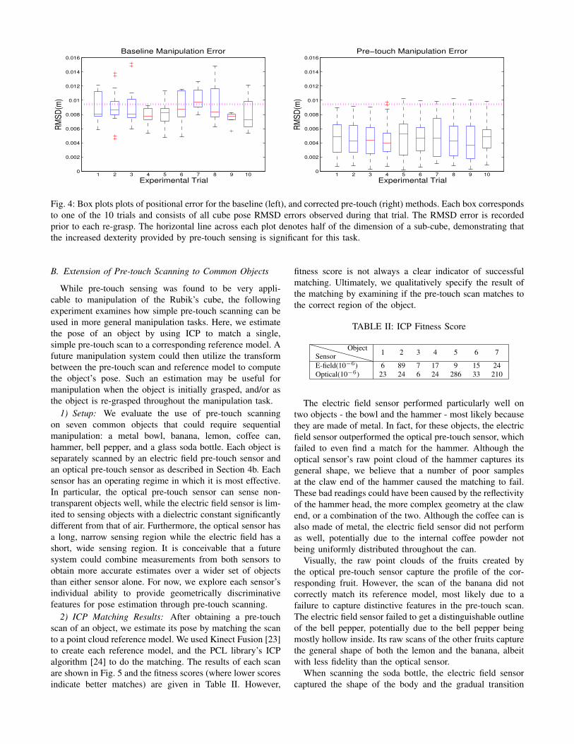
3) Intermediate Pose Estimation: Comparing the robot’spositional estimate of the Rubik’s cube for both methodsto the ground truth values also yields interesting results. Therobot re-estimated the pose of the cube prior to each re-grasp.For each pose estimate, the error was calculated as the root-mean-square deviation (RMSD) between the x and z axesof the estimate and the recorded ground-truth. The RMSDthroughout each trial for both methods are summarized asbox plots in Fig. 4.
The observed errors demonstrate that pre-touch sensingallowed the robot to significantly reduce the amount of errorin the robot’s estimate of the pose of the Rubik’s cube.The robot has a finger width that is approximately equalto the size of a sub-cube of the Rubik’s cube. Given thatthe desired grasp point is exactly in-between two sub-cubes,the margin of acceptable error is approximately half thewidth of a sub-cube. More error than this could cause therobot to unintentionally constrain one of the faces, causinga future manipulation to fail. Alternatively, error above thisthreshold could cause the robot to fail to even grasp the cube.The left plot of Fig. 4 demonstrates that for most trials, alarge portion of the baseline method’s pose estimates had anRMSD significantly larger than half of the size of a sub-cube.In contrast, the right plot shows that the RMSD of pre-touchaided estimates very rarely went above this threshold. In fact,for the pre-touch enabled method, most pose estimates hadan RMSD of less than 0.8cm. Thus, through the use of pre-touch scanning, the robot has been able to limit the errorin its estimate of the cube’s pose and thereby solve it morerobustly.
0
0.002
0.004
0.006
0.008
0.01
0.012
0.014
0.016
1 2 3 4 5 6 7 8 9 10
Experimental Trial
Baseline Manipulation ErrorR
MS
D(m
)
0
0.002
0.004
0.006
0.008
0.01
0.012
0.014
0.016
1 2 3 4 5 6 7 8 9 10
Experimental Trial
Pre−touch Manipulation Error
RM
SD
(m)
Fig. 4: Box plots plots of positional error for the baseline (left), and corrected pre-touch (right) methods. Each box correspondsto one of the 10 trials and consists of all cube pose RMSD errors observed during that trial. The RMSD error is recordedprior to each re-grasp. The horizontal line across each plot denotes half of the dimension of a sub-cube, demonstrating thatthe increased dexterity provided by pre-touch sensing is significant for this task.
B. Extension of Pre-touch Scanning to Common Objects
While pre-touch sensing was found to be very appli-cable to manipulation of the Rubik’s cube, the followingexperiment examines how simple pre-touch scanning can beused in more general manipulation tasks. Here, we estimatethe pose of an object by using ICP to match a single,simple pre-touch scan to a corresponding reference model. Afuture manipulation system could then utilize the transformbetween the pre-touch scan and reference model to computethe object’s pose. Such an estimation may be useful formanipulation when the object is initially grasped, and/or asthe object is re-grasped throughout the manipulation task.
1) Setup: We evaluate the use of pre-touch scanningon seven common objects that could require sequentialmanipulation: a metal bowl, banana, lemon, coffee can,hammer, bell pepper, and a glass soda bottle. Each object isseparately scanned by an electric field pre-touch sensor andan optical pre-touch sensor as described in Section 4b. Eachsensor has an operating regime in which it is most effective.In particular, the optical pre-touch sensor can sense non-transparent objects well, while the electric field sensor is lim-ited to sensing objects with a dielectric constant significantlydifferent from that of air. Furthermore, the optical sensor hasa long, narrow sensing region while the electric field has ashort, wide sensing region. It is conceivable that a futuresystem could combine measurements from both sensors toobtain more accurate estimates over a wider set of objectsthan either sensor alone. For now, we explore each sensor’sindividual ability to provide geometrically discriminativefeatures for pose estimation through pre-touch scanning.
2) ICP Matching Results: After obtaining a pre-touchscan of an object, we estimate its pose by matching the scanto a point cloud reference model. We used Kinect Fusion [23]to create each reference model, and the PCL library’s ICPalgorithm [24] to do the matching. The results of each scanare shown in Fig. 5 and the fitness scores (where lower scoresindicate better matches) are given in Table II. However,
fitness score is not always a clear indicator of successfulmatching. Ultimately, we qualitatively specify the result ofthe matching by examining if the pre-touch scan matches tothe correct region of the object.
TABLE II: ICP Fitness Score
SensorObject 1 2 3 4 5 6 7
E-field(10−6) 6 89 7 17 9 15 24Optical(10−6) 23 24 6 24 286 33 210
The electric field sensor performed particularly well ontwo objects - the bowl and the hammer - most likely becausethey are made of metal. In fact, for these objects, the electricfield sensor outperformed the optical pre-touch sensor, whichfailed to even find a match for the hammer. Although theoptical sensor’s raw point cloud of the hammer captures itsgeneral shape, we believe that a number of poor samplesat the claw end of the hammer caused the matching to fail.These bad readings could have been caused by the reflectivityof the hammer head, the more complex geometry at the clawend, or a combination of the two. Although the coffee can isalso made of metal, the electric field sensor did not performas well, potentially due to the internal coffee powder notbeing uniformly distributed throughout the can.
Visually, the raw point clouds of the fruits created bythe optical pre-touch sensor capture the profile of the cor-responding fruit. However, the scan of the banana did notcorrectly match its reference model, most likely due to afailure to capture distinctive features in the pre-touch scan.The electric field sensor failed to get a distinguishable outlineof the bell pepper, potentially due to the bell pepper beingmostly hollow inside. Its raw scans of the other fruits capturethe general shape of both the lemon and the banana, albeitwith less fidelity than the optical sensor.
When scanning the soda bottle, the electric field sensorcaptured the shape of the body and the gradual transition

Fig. 5: The results of applying pre-touch scanning and ICP to seven common objects. The first column shows each of theseven objects and the region that was scanned in green. The second column shows the raw point cloud obtained by theelectric field sensor for each object, and the third column shows how the ICP algorithm matched the raw point cloud to thereference model. The raw point cloud is colored green if the ICP algorithm found a correct partial or full match, and red ifit failed. The fourth and fifth columns display the analogous results for the optical pre-touch scans.

from the body to the neck well. The matching gives avery rough estimate of the pose of the bottle. Note thatthe reference model was obtained by wrapping the bottlein opaque tape because transparent objects are difficult forthe Kinect to sense. Accordingly, the optical pre-touch sensordid very poorly when scanning the uncovered bottle.
This experiment has demonstrated that for many objects,a single, simple scan is sufficient to get a good estimate ofthe pose of the object. Furthermore, only the electric fieldscan of the bell pepper and the optical scan of the bottlecompletely failed to retrieve any geometric information. Thisis encouraging because when one sensor completely failed,the other was able to capture at least some geometric infor-mation. Furthermore, it is possible that a method specificallydesigned to match these types of 1D scans to referencemodels would produce even better results than off-the-shelfICP. It is therefore feasible that a system employing multiplescans with both of the sensors could have a robust ability torecover the pose of a wide range of objects.
VI. CONCLUSION
This work presented methods for using pre-touch scanningto help robots perform sequential manipulation. We firstdeveloped a new optical time-of-flight pre-touch sensor thatis composed of inexpensive components. We then showedthat this pre-touch sensor allows the robot to precisely re-estimate the pose of the Rubik’s cube, endowing the robotwith the dexterity necessary to robustly solve the cube.Finally, through the use of ICP, we extended pre-touchscanning to pose estimation of seven common objects andshowed that even a single, simple scan can capture enoughgeometric information to perform the estimation well.
Now that we have demonstrated the utility of pre-touchscanning in achieving sequential manipulation, there areseveral directions in which we would like continue our work.One area is to explore how the robot can determine whereto scan and how to generate a trajectory that has a highprobability of capturing useful geometric information. Inconjunction with this direction, we are also interested inhow robots can use electric field sensors to create electricfield images. Furthermore, we will aim to develop metricsfor the quality of an executed scan. Such metrics will beimportant if the robot is trying to manipulate objects thathave the potential to not be well detected by one or more ofits sensors. Finally, we would like to examine how multiplemodalities of pre-touch scanning can most effectively befused together for the purpose of robot manipulation.
REFERENCES
[1] C. C. Kemp, A. Edsinger, and E. Torres-Jara, “Challenges for robotmanipulation in human environments,” IEEE Robotics and AutomationMagazine, vol. 14, no. 1, p. 20, 2007.
[2] T. Rokicki, H. Kociemba, M. Davidson, and J. Dethridge, “Thediameter of the rubik’s cube group is twenty,” SIAM Review, vol. 56,no. 4, pp. 645–670, 2014.
[3] J. Maitin-Shepard, M. Cusumano-Towner, J. Lei, and P. Abbeel, “Clothgrasp point detection based on multiple-view geometric cues withapplication to robotic towel folding,” in Robotics and Automation(ICRA), 2010 IEEE International Conference on. IEEE, 2010, pp.2308–2315.
[4] L.-Y. Chang, J. R. Smith, and D. Fox, “Interactive singulation ofobjects from a pile,” in Robotics and Automation (ICRA), 2012 IEEEInternational Conference on. IEEE, 2012, pp. 3875–3882.
[5] N. Vahrenkamp, S. Wieland, P. Azad, D. Gonzalez, T. Asfour, andR. Dillmann, “Visual servoing for humanoid grasping and manipula-tion tasks,” in Humanoid Robots, 2008. Humanoids 2008. 8th IEEE-RAS International Conference on. IEEE, 2008, pp. 406–412.
[6] D. Kragic, H. I. Christensen et al., “Survey on visual servoing for ma-nipulation,” Computational Vision and Active Perception Laboratory,Fiskartorpsv, vol. 15, 2002.
[7] R. Li, R. Platt, W. Yuan, A. ten Pas, N. Roscup, M. A. Srinivasan,and E. Adelson, “Localization and manipulation of small parts usinggelsight tactile sensing,” in Intelligent Robots and Systems (IROS2014), 2014 IEEE/RSJ International Conference on. IEEE, 2014,pp. 3988–3993.
[8] A. Petrovskaya and O. Khatib, “Global localization of objects viatouch,” Robotics, IEEE Transactions on, vol. 27, no. 3, pp. 569–585,2011.
[9] K. Hsiao, P. Nangeroni, M. Huber, A. Saxena, and A. Y. Ng, “Reactivegrasping using optical proximity sensors,” in Robotics and Automation,2009. ICRA’09. IEEE International Conference on. IEEE, 2009, pp.2098–2105.
[10] A. Maldonado, H. Alvarez, and M. Beetz, “Improving robot manipu-lation through fingertip perception,” in Intelligent Robots and Systems(IROS), 2012 IEEE/RSJ International Conference on. IEEE, 2012,pp. 2947–2954.
[11] D. Guo, P. Lancaster, L.-T. Jiang, F. Sun, and J. R. Smith, “Trans-missive optical pretouch sensing for robotic grasping,” in IntelligentRobots and Systems (IROS), 2015 IEEE/RSJ International Conferenceon. IEEE, 2015, pp. 5891–5897.
[12] J. R. Smith, E. Garcia, R. Wistort, and G. Krishnamoorthy, “Electricfield imaging pretouch for robotic graspers,” in Intelligent Robots andSystems, 2007. IROS 2007. IEEE/RSJ International Conference on.IEEE, 2007, pp. 676–683.
[13] R. Wistort and J. R. Smith, “Electric field servoing for roboticmanipulation,” in Intelligent Robots and Systems, 2008. IROS 2008.IEEE/RSJ International Conference on. IEEE, 2008, pp. 494–499.
[14] B. Mayton, L. LeGrand, and J. R. Smith, “An electric field pretouchsystem for grasping and co-manipulation,” in Robotics and Automation(ICRA), 2010 IEEE International Conference on. IEEE, 2010, pp.831–838.
[15] S. Muhlbacher-Karrer, A. Gaschler, and H. Zangl, “Responsive finger-scapacitive sensing during object manipulation,” in Intelligent Robotsand Systems (IROS), 2015 IEEE/RSJ International Conference on.IEEE, 2015, pp. 4394–4401.
[16] L.-T. Jiang and J. R. Smith, “Seashell effect pretouch sensing forrobotic grasping,” in Robotics and Automation (ICRA), 2012 IEEEInternational Conference on. IEEE, 2012, pp. 2851–2858.
[17] A. Leeper, K. Hsiao, E. Chu, and J. K. Salisbury, “Using near-field stereo vision for robotic grasping in cluttered environments,” inExperimental Robotics. Springer, 2014, pp. 253–267.
[18] G. Kahn, P. Sujan, S. Patil, S. Bopardikar, J. Ryde, K. Goldberg, andP. Abbeel, “Active exploration using trajectory optimization for roboticgrasping in the presence of occlusions,” in Robotics and Automation(ICRA), 2015 IEEE International Conference on. IEEE, 2015, pp.4783–4790.
[19] B. Calli, A. Walsman, A. Singh, S. Srinivasa, P. Abbeel, and A. M.Dollar, “Benchmarking in manipulation research: Using the yale-cmu-berkeley object and model set,” Robotics & Automation Magazine,IEEE, vol. 22, no. 3, pp. 36–52, 2015.
[20] C. Zieliski, T. Winiarski, W. Szynkiewicz, M. Staniak, W. Czajewski,and T. Kornuta, “Mrroc++ based controller of a dual arm robot systemmanipulating a rubiks cube,” Citeseer, Tech. Rep., 2007.
[21] L. Riano. (2011) pr2 rubiks solver. [Online]. Available: https://github.com/uu-isrc-robotics/pr2 rubiks solver
[22] Proximity and ambient light sensing (ALS) module, ST Microelectron-ics, 8 2014, rev. 6.
[23] R. A. Newcombe, S. Izadi, O. Hilliges, D. Molyneaux, D. Kim,A. J. Davison, P. Kohi, J. Shotton, S. Hodges, and A. Fitzgibbon,“Kinectfusion: Real-time dense surface mapping and tracking,” inMixed and augmented reality (ISMAR), 2011 10th IEEE internationalsymposium on. IEEE, 2011, pp. 127–136.
[24] D. Holz, A. E. Ichim, F. Tombari, R. B. Rusu, and S. Behnke,“Registration with the point cloud library: A modular framework foraligning in 3-d,” IEEE Robotics & Automation Magazine, vol. 22,no. 4, pp. 110–124, 2015.