Embed Size (px)
Citation preview

Apple PowerBook G4 17”PRAM Battery
Installation Manual
Your computer is a static-sensitive device. It is susceptible to invisible damage if not protected during installation.
We recommend proper grounding by using a grounding strap. Make sure to work in a clean and static-free area, and avoid wearing clothing that retains static charges.
Although these instructions should provide enough detail for almost anyone to install replacement components, if you are not comfortable opening your Mac, or do not have the required tools to avoid damage to your computer, you can always contact Other World Computing to install it for you.
Got tools? If you don’t have the tools necessary to complete this installation, Newer Technology has a fantastic toolkit with everything you need included to perform this installation, and most common com-puter hardware installations.
It’s available at:http://eshop.macsales.com/item/Newer%20Technology/TOOLKIT11/

PRAM battery replacement - PowerBook G4 17”
Tools Needed• #0 Philips Screwdriver• Torx T8 Screwdriver• Nylon pry tool
DisassemblyStep 1Shut Down your PowerBook G4 completely. Unplug the power cord and remove the battery.
Step 2Turn your PowerBook over and remove it’s battery.
Step 3Remove the 3 Phillips screws securing the metal cover over the RAM modules and also the 3 Phillips screws at the front inside edge of the battery bay. Be sure to keep them sorted apart - the screws inside the edge of the battery bay are very short, only 1.3mm long. The screws that hold the memory cover on are longer at 2.2mm.

Step 4Remove the 5 Phillips screws from the back edge of the PowerBook G4. There are 2 sizes of screws here - the interior 3 are 12.35mm long, and the outside 2 are longer at 14.85mm long.
Step 5Remove the 2 Torx T-8 screws circled above. The one in the middle of the logic board is shorter than the other, the left one in this picture is 6.8mm, the short one is 3.8mm.
Step 6 & 7Remove the 4 Phillips screws on each side of the PowerBook G4, 8 screws total (they are identical length).
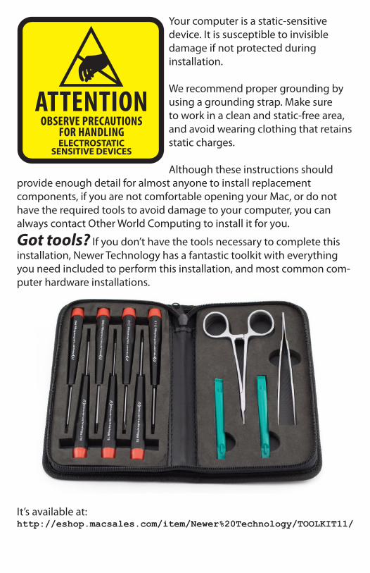
Step 8*Be very careful with this connector, it is extremely fragile*
Remove the memory module closest to the battery bay and you will expose the ribbon cable that connects the top cover to the logic board. The connector plugs into a socket that is compression fit with a small brown plastic wedge. You need to gently unlock the wedge by lifting it towards the ribbon, it does not completely come off of the white body of the connector, it’s got small clips that retain it on the connector itself.
Using your fingernails or a plastic pry tool, just push half of the brown connector up about 1/16” from the white body of the connector, and re-peat on the opposite side. Do this a couple of times, and you will unlock the ribbon cable.
Once the ribbon cable is free, lift it out of the body of the connector, place the brown clamp back into the connector to make sure it does not fall out, and lift the ribbon cable straight up to aid in removal of the rib-bon in a future step.
Step 9Turn the PowerBook G4 back over onto it’s feet and open it up as far as it will go. Starting at the back of the top cover, above the speakers, gently lift upwards on the top cover, it should lift off without much resistance.
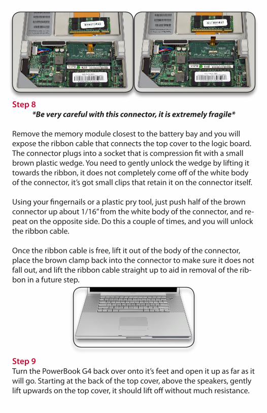
Step 10You now have exposed the optical drive, which also has to be removed to gain access to the PRAM battery.
Step 11You now have exposed the optical drive, which also has to be removed to gain access to the PRAM battery. Start by removing the 4 Torx T8 screws that fasten it into the chassis. The bottom right screw is shorter than the other 3 - they are 6.8mm and 3.8mm long respectively.

Step 12At the top of the optical drive you will see the ribbon cable that con-nects the logic board to the backup battery. You need to remove this cable to be able to take the optical drive out of the computer. The rib-bon cable is the same process as the connector you removed to take the top cover off of the computer. Remove the ribbon from the logic board connector and then do the same thing with the opposite side of that cable, you may not be able to fully unclip the connector as it’s a bit un-der the optical drive - if you have difficulty, leave it till you are removing the drive then the connector will be free to move upwards further.
Step 13Finally, you need to disconnect the ribbon cable that attaches the opti-cal drive to the logic board. Very gently rock the cable back and forth on the logic board, while lifting with your fingernails on the left and right side, wiggling the cable off of the logic board.

Step 14In this photo you see the battery backup cable removed. If you had dif-ficulty with the connector at the edge of the optical drive, lift up on the drive and remove it now.
Step 15On the right side of the optical bay you see the black covered battery backup module. There are 2 Torx T-8 screws securing it to the chassis - remove them, and the module will come out of the chassis. Slide the black plastic shield off of the module, and you will expose the backup battery. Simply unplug it from the module, and replace with your new battery. Reverse these steps to reassemble your PowerBook G4.
NWTMANPB17PRAM