Embed Size (px)
DESCRIPTION
dv
Citation preview
7/21/2019 PracticalApproach to dc
http://slidepdf.com/reader/full/practicalapproach-to-dc 1/12
A Practical Approach to Line Current
Differential Testing
Karl Zimmerman and David Costello
Schweitzer Engineering Laboratories, Inc.
© 2013 IEEE. Personal use of this material is permitted. Permission from IEEE must be obtained
for all other uses, in any current or future media, including reprinting/republishing this material
for advertising or promotional purposes, creating new collective works, for resale or
redistribution to servers or lists, or reuse of any copyrighted component of this work in other
works.
This paper was presented at the 66th Annual Conference for Protective Relay Engineers.
For the complete history of this paper, refer to the next page.

7/21/2019 PracticalApproach to dc
http://slidepdf.com/reader/full/practicalapproach-to-dc 2/12
Presented at the
67th Annual Georgia Tech Protective Relaying Conference
Atlanta, Georgia
May 8–10, 2013
Originally presented at the
66th Annual Conference for Protective Relay Engineers, April 2013

7/21/2019 PracticalApproach to dc
http://slidepdf.com/reader/full/practicalapproach-to-dc 3/12
1
A Practical Approach to Line Current
Differential Testing
Karl Zimmerman and David Costello, Schweitzer Engineering Laboratories, Inc.
Abstract— Line current differential (87L) protection of
transmission lines is preferred because of its speed, sensitivity,
security, and selectivity. 87L scheme performance is dependent
on reliable communications, because measured currents from all
terminals must be communicated and time-aligned.
Several misoperations due to channel problems and noise led
to the implementation of disturbance detectors and watchdog
counters to increase scheme security in newer relay designs.
While these features increase security, they can complicate
testing and led to the implementation of “test mode,” the ability
to simplify 87L testing while bypassing some of the relay security
logic.
Practical testing recommendations are presented in this
paper. Several common 87L testing scenarios are discussed,including single-relay tests using loopback communications,
single-relay tests of the operating and restrain characteristics of
the relay using test mode, multiple-relay tests of the
characteristics and channel using test mode, and multiple-relay
tests of the characteristics and channel without test mode where
real-world conditions are simulated.
I. I NTRODUCTION
Line current differential (87L) protection is applied on long
and short lines and on various voltage levels. Because the
relays are located independently at each terminal of a line,
87L schemes depend on reliable communications to exchange
and align the currents. Modern 87L schemes account foractual power system conditions more than their predecessors
by implementing security improvements such as local and
remote disturbance detection, watchdog counters, advanced
time alignment and fallback methods, line charging current
compensation, and external fault detection.
Some of these advancements affect 87L scheme testing by
making it necessary for engineers and technicians to apply
system conditions that more closely replicate power system
conditions or, in some cases, to use a “test mode” for testing
certain functions.
This paper presents some practical recommendations for
testing 87L schemes. Several single-ended and multi-ended
scenarios are discussed, including multi-ended 87L schemetesting where real-world conditions are simulated.
II. R EVIEW OF MODERN 87L PROTECTION
Digital 87L systems are popular for a number of reasons.
As with any differential scheme, 87L systems offer sensitivity,
security, and selectivity. These systems provide fast and
simultaneous fault clearing for faults located anywhere along a
protected transmission line. Fig. 1 shows a one-line diagram
of a typical two-terminal 87L scheme.
Fig. 1. Two-Terminal Digital 87L Application.
87L systems are applicable to both long and short lines and
are a good solution for complicated applications, such as
series-compensated lines, multiple-terminal lines, and lines
with zero-sequence mutual coupling. They perform well for
evolving faults, intercircuit and cross-country faults, internal
faults with outfeed, current reversals, and power swings.
Typical challenges for these systems include line charging
current, in-line and tapped transformers, and current
transformer (CT) saturation during external faults [1]. Also,
these systems require a reliable, high-capacity, low-latency
communications channel and must reliably time-align currents
sampled at remote terminals in spite of channel noise, delays,
and asymmetry [2].
Traditional current differential schemes use a percentage
restraint characteristic. Operate, or difference, current is
calculated as the magnitude of the sum of the terminal current
phasors. Restraint current is a measure of the terminal current
magnitudes and, depending on design, could be the sum of the
terminal current magnitudes, the average of the terminal
current magnitudes, and so on. The differential relaytraditionally operates when the operate current exceeds a
7/21/2019 PracticalApproach to dc
http://slidepdf.com/reader/full/practicalapproach-to-dc 4/12
2
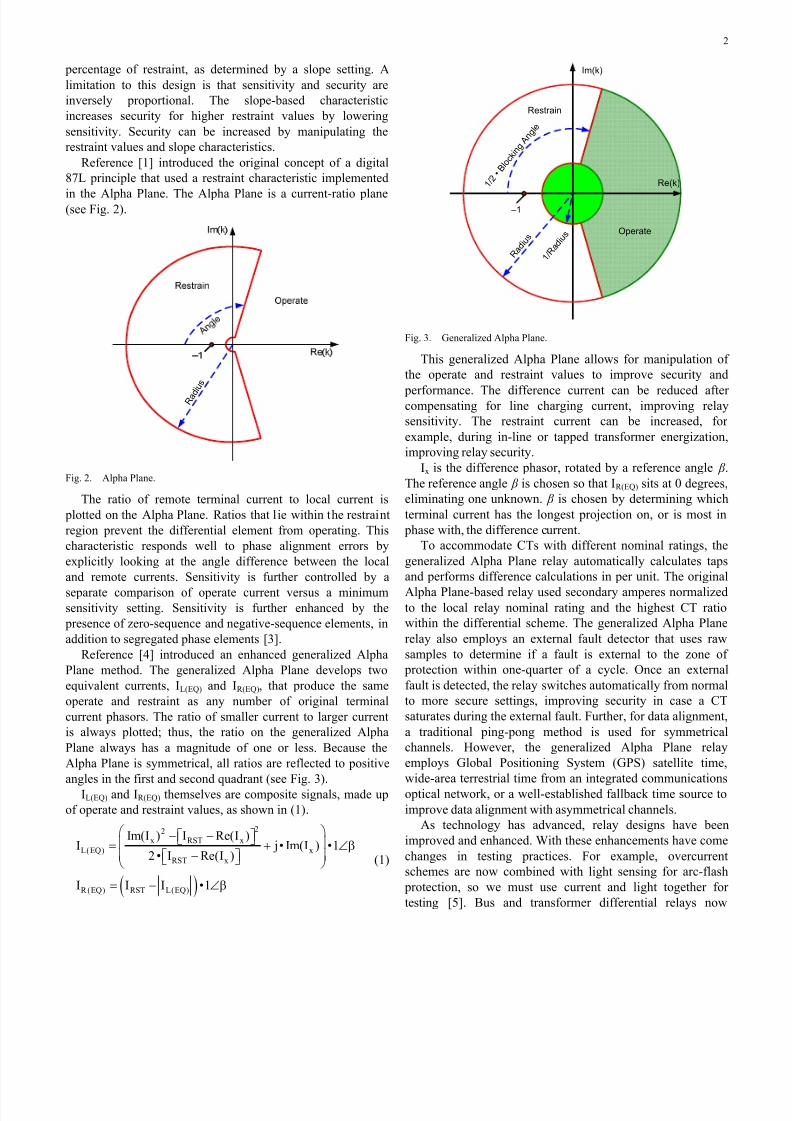
percentage of restraint, as determined by a slope setting. A
limitation to this design is that sensitivity and security are
inversely proportional. The slope-based characteristic
increases security for higher restraint values by lowering
sensitivity. Security can be increased by manipulating the
restraint values and slope characteristics.
Reference [1] introduced the original concept of a digital
87L principle that used a restraint characteristic implemented
in the Alpha Plane. The Alpha Plane is a current-ratio plane(see Fig. 2).
R a d i u
s
Fig. 2. Alpha Plane.
The ratio of remote terminal current to local current is
plotted on the Alpha Plane. Ratios that lie within the restraint
region prevent the differential element from operating. This
characteristic responds well to phase alignment errors by
explicitly looking at the angle difference between the local
and remote currents. Sensitivity is further controlled by a
separate comparison of operate current versus a minimumsensitivity setting. Sensitivity is further enhanced by the
presence of zero-sequence and negative-sequence elements, in
addition to segregated phase elements [3].
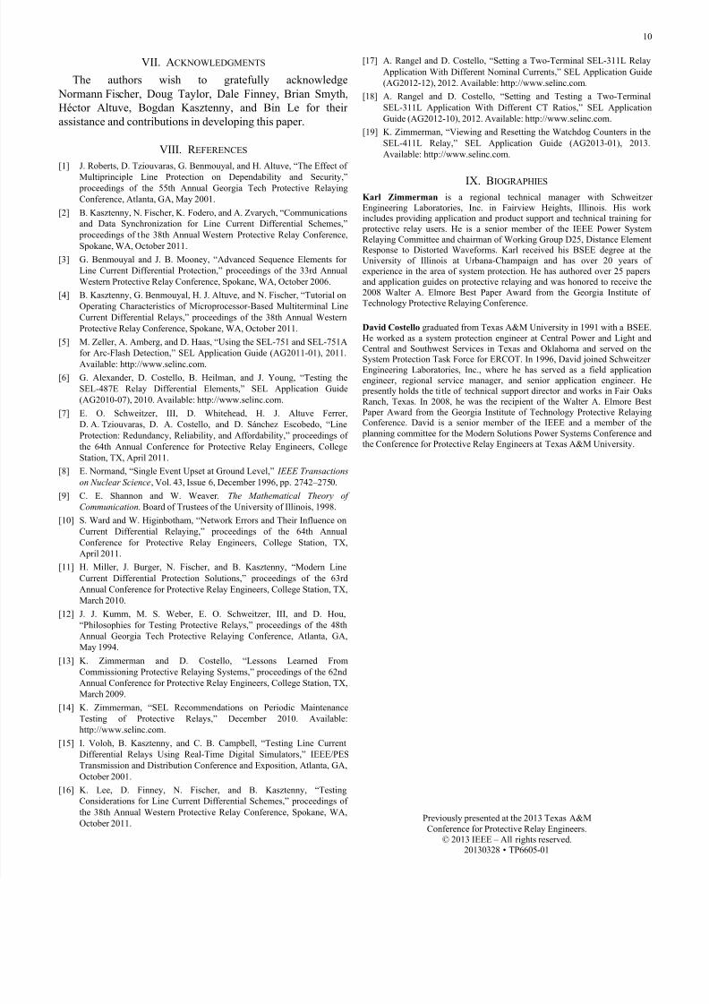
Reference [4] introduced an enhanced generalized Alpha
Plane method. The generalized Alpha Plane develops two
equivalent currents, IL(EQ) and IR(EQ), that produce the same
operate and restraint as any number of original terminal
current phasors. The ratio of smaller current to larger current
is always plotted; thus, the ratio on the generalized Alpha
Plane always has a magnitude of one or less. Because the
Alpha Plane is symmetrical, all ratios are reflected to positive
angles in the first and second quadrant (see Fig. 3).
IL(EQ) and IR(EQ) themselves are composite signals, made up
of operate and restraint values, as shown in (1).
( )
22x RST x
L(EQ) x
RST x
R(EQ) RST L(EQ)
Im(I ) I Re(I )I j• Im(I ) •1
2• I Re(I )
I I I •1
⎛ ⎞− −⎡ ⎤⎣ ⎦⎜ ⎟= + ∠β⎜ ⎟−⎡ ⎤⎣ ⎦⎝ ⎠
= − ∠β
(1)
Im(k)
Re(k)
Restrain
Operate
1 / 2
• B l o
c k i n
g A n g l e
–1
R a d i u
s
1 / R
a d i u
s
Fig. 3. Generalized Alpha Plane.
This generalized Alpha Plane allows for manipulation of
the operate and restraint values to improve security and
performance. The difference current can be reduced aftercompensating for line charging current, improving relay
sensitivity. The restraint current can be increased, for
example, during in-line or tapped transformer energization,
improving relay security.
Ix is the difference phasor, rotated by a reference angle β .
The reference angle β is chosen so that IR(EQ) sits at 0 degrees,
eliminating one unknown. β is chosen by determining which
terminal current has the longest projection on, or is most in
phase with, the difference current.
To accommodate CTs with different nominal ratings, the
generalized Alpha Plane relay automatically calculates taps
and performs difference calculations in per unit. The original
Alpha Plane-based relay used secondary amperes normalizedto the local relay nominal rating and the highest CT ratio
within the differential scheme. The generalized Alpha Plane
relay also employs an external fault detector that uses raw
samples to determine if a fault is external to the zone of
protection within one-quarter of a cycle. Once an external
fault is detected, the relay switches automatically from normal
to more secure settings, improving security in case a CT
saturates during the external fault. Further, for data alignment,
a traditional ping-pong method is used for symmetrical
channels. However, the generalized Alpha Plane relay
employs Global Positioning System (GPS) satellite time,
wide-area terrestrial time from an integrated communications
optical network, or a well-established fallback time source to
improve data alignment with asymmetrical channels.
As technology has advanced, relay designs have been
improved and enhanced. With these enhancements have come
changes in testing practices. For example, overcurrent
schemes are now combined with light sensing for arc-flash
protection, so we must use current and light together for
testing [5]. Bus and transformer differential relays now

7/21/2019 PracticalApproach to dc
http://slidepdf.com/reader/full/practicalapproach-to-dc 5/12
3
automatically switch to a higher percentage slope setting for
better security during external faults, so we must apply
dynamic state simulations to precisely test the higher slope
setting [6]. Similarly, technology advancements have been
introduced in 87L elements.
Some of these advancements have led to improvements in
the security of the 87L performance and with it, changes in the
approach to testing. As we see in the following section, 87L
elements have proven to be more secure, on the average, thanmost protection schemes. Still, we evaluate several system
events to root cause to show why we wish to further improve
87L security.
III. 87L PERFORMANCE WITH CASE STUDIES
The rate of total observed undesired operations in
numerical relays is extremely low, 0.0333 percent per year (a
failure rate of 333 • 10 –6
). By comparison, relay application
and setting errors (human factors) are 0.1 percent per year (a
failure rate of 1,000 • 10 –6) [7]. The rate of total observed
undesired operations in 87L schemes is even lower,
0.016 percent per year (a failure rate of 160 • 10 –6
). If
disturbance detection (described later in this paper) had been
applied in all cases, this number would drop even lower, to
0.009 percent per year (a failure rate of 90 • 10 –6).
Some of these undesired operations were due to single
event upsets (SEUs) [8], sometimes called soft memory errors,
in relays. Diagnostics have greatly improved and reduced
these errors in the last several years. The rate of observed 87L
undesired operations due to channel problems is less than
0.002 percent per year (a failure rate of 20 • 10 –6). Had
disturbance detection been applied in all cases, this number
would drop even lower, to less than 0.0005 percent per year (a
failure rate of 5 • 10 –6).
All this is to say that protective relays are very secure. Still,every undesired operation is cause for concern and drives
efforts to identify, measure, and improve. In the following
discussion, we analyze three actual events that produced an
undesired 87L operation.
A. Case Study 1: 87L Misoperation Caused by an SEU
Fig. 4 shows an event where there was no apparent fault. In
this case, 87L asserted and produced an undesired trip, and the
root cause was attributed to an SEU, also called a soft memory
error. An SEU is a temporary unintended change of state in a
single memory location. Soft memory failures are transient,
infrequent events occurring at a rate of about one per million
memory-device operating hours. Such errors are caused byhigh-energy particles striking a memory storage capacitance
and disturbing the charge stored at a particular location. These
high-energy particles can come from high-energy cosmic rays
or from the emission of alpha particles from impurities in
some microcircuit packaging materials. Improvements in
internal diagnostics and memory storage design have been
implemented to reduce the occurrence of these events.
Enhanced firmware now detects the soft memory error event,
automatically resets the relay, pulses the alarm contact, and
logs an entry in the sequence-of-events record. In rare cases,
SEUs can cause a change of state in an element that produces
a trip, like that shown in Fig. 4.
Fig. 4. 87L Asserts for an SEU.
B. Case Study 2: 87L Misoperation Due to a Channel
Problem With Disturbance Detector Disabled
In the system event shown in Fig. 5, the channel
experiences a degradation of the output of one of the optical
fiber transmitters used in the 87L scheme. We can observe the
ROKX bit chattering (it should be solidly asserted).
Eventually, bad data (erroneous remote current IBX) make it
through error checking to cause an undesired 87L operation.
In this case, disturbance detection was disabled. If it had
been enabled, the 87L element would have been prevented
from tripping instantaneously, and the undesired operation
would have been avoided. Early 87L relays had a setting to
enable (or disable) disturbance detection at the local terminal. Newer relays use disturbance detection at all terminals by
design.
Fig. 5. 87L Produces Undesired Trip During Communications Failure With
Disturbance Detection Not Enabled.

7/21/2019 PracticalApproach to dc
http://slidepdf.com/reader/full/practicalapproach-to-dc 6/12
4
C. Case Study 3: 87L Misoperates With Disturbance Detector
Enabled
In Fig. 6, an apparent communications error produces a trip
condition. In this case, even with disturbance detection logic
enabled, the trip was not prevented.
Fig. 6. Apparent Communications Error Produces 87L Misoperation WithDisturbance Detection Logic Enabled.
Monitoring the performance of the 87L scheme over time
using advanced channel diagnostics and alarms is a method to
secure the relay for such events, as discussed in the following
section. In original designs, channel monitoring and poor
channel performance could be ignored or missed by users.
Watchdog counters now disable the 87L element for repeated
close calls.
IV. SECURITY IMPROVEMENTS
A. Data Integrity Check
Noise in the communications channel can corrupt data. The
term noise refers to such issues as interference coupled to the
channel media or electronics, failing components used in the
network, poor quality of fiber terminations and associated
losses, and marginal power budget for fiber transceivers. In
multiplexed networks, frame slips can corrupt the data.
Noise is not necessarily a sporadic event. A failing
component in the communications channel can create a
persistent noise that is constantly threatening the integrity of
the transmitted 87L data. Undetected errors can lead to 87L
misoperation. Detected errors cause a temporary loss of
dependability because the relay needs to flush the bad data or
to resynchronize.
Solutions include using a data integrity check, such as a
Bose, Ray-Chaudhuri, Hocquenghem (BCH) code check. Thesecurity is based on the bit check resolution and packet size.
For example, a 32-bit BCH code used on a 255-bit packet size
secures the data so that the probability of undetected error is
less than 1.2 • 10 –10
[9] [10].
B. Disturbance Detection Supervision
Even with powerful data integrity checks, additional
security is needed because 87L schemes exchange so much
data. For example, by sending packets every 4 milliseconds, a
relay transmits and receives 7.884 billion packets per year.
Even with a very small probability of an undetected error
(1.2 • 10 –10), a standing noise in the communications channel
could possibly produce corrupted data and potentially an
undesired 87L operation [11].
As seen in Section III, Subsection B, applying disturbance
detection improves security. Typically, a disturbance detector
(DD) looks for a change in measured current compared to the
current one cycle ago (or within a similar window). Schemes
can use the local data, or both the local and remote data, tosupervise instantaneous tripping of an 87L element. Typically,
the raw (unsupervised) 87L is allowed to trip without DD
supervision after a short time delay (for example, two cycles).
Fig. 7 shows disturbance detection logic using both local and
remote (87DDL and 87DDR) data to supervise 87L trips as
well as a received direct transfer trip (87DTT).
Fig. 7. 87L Disturbance Detection Logic.
Disturbance detection logic impacts testing in three ways.
First, if DD uses local and remote data, a single-ended test isinadequate. The local 87L would always experience a time
delay. Second, slowly ramping a current from a prefault to a
fault value is inadequate. A step change in current (or voltage,
if used) is realistic and required; otherwise, DDs will not
assert. The relay would again trip with a time delay. Third,
raw 87L operations without accompanying DD may
eventually disable the 87L element due to channel monitoring
and improved security. This will be discussed in more detail
shortly.
As we can see, to properly test an 87L element with
disturbance detection, the test quantities must closely replicate
an actual fault.
C. Watchdog Counters
It may happen that the raw 87L element picks up due to
noise but does not operate because it is initially stopped by the
lack of disturbance (no sensitive DDs assert at the same time
as the 87L operation). Afterwards, the 87L resets itself when
the channel problem disappears.
For this reason, it is important to log such events as close
calls and incorporate logic that responds to unexpected and
persistent events that impact the 87L function. This logic,
called a watchdog counter, maintains the security of the 87L

7/21/2019 PracticalApproach to dc
http://slidepdf.com/reader/full/practicalapproach-to-dc 7/12
5
function by first alerting the user about significant channel
issues through alarms to force rectification of the channel
problems. Second, watchdog counters may inhibit the 87L
function after a significant number of persistent events or
close calls so that misoperations are prevented.
Watchdog counters impact testing. If users insist on testing
relay schemes with in-service settings and no special test
mode(s), then the testing method must emulate actual power
system conditions. If testing is not realistic, the watchdogcounters log unexpected 87L events and eventually inhibit the
87L element during testing.
Consider an analogy to loss-of-potential (LOP) logic in
distance (21) or directional (67) element schemes. In the case
of a failed voltage transformer (VT), VT wiring problem, or
blown VT fuse, users can decide through relay settings
whether to inhibit 21 or 67 elements, or both. Alternatively,
the user may decide to simply leave the elements to operate
based on unreliable voltages. In either case, the user may
choose to alarm and call immediate attention to the problem.
Similarly, the user must decide to enable or to disable 87L
watchdog counter supervision to determine how the 87L
element behaves if a communications channel is deemed tohave had too many close calls.
D. Generalized Alpha Plane Increases Security for Advanced
Requirements
The generalized Alpha Plane is transparent for common
two-terminal applications, while allowing the same principle
to be applied to three-terminal (or x-terminal) lines by
reducing the system to a two-terminal equivalent, as described
in Section II. Keep in mind, a two-terminal transmission line
with dual breakers at each terminal is a four-terminal
differential problem.
Moreover, if applied on lines with charging current, the
total charging current can be removed, bringing the balancedcurrent closer to the ideal blocking point (1 per unit at
180 degrees). For applications with in-line transformers or any
other case where higher restraint is required, harmonics can be
added to the restraint, thus moving the Alpha Plane point
closer to the ideal blocking point. By using external fault
detection, the differential can be placed in a high-security
mode—essentially increasing the Alpha Plane restraint region.
Moreover, these principles can be applied on segregated
phase, negative-sequence, and zero-sequence quantities alike.
E. Advanced Time Alignment
In addition to traditional channel-based data alignment
using a ping-pong method, modern relays can use externaltime sources, if desired. These time sources are useful when
applying 87L over a network that may experience
asymmetrical channel delays.
When high-accuracy GPS clocks are used, data can be
synchronized without compensating for clock offset. This
reduces concerns of channel asymmetry and channel
switching because the time source is independent of the
channel.
Finally, if a time source is lost or degrades, schemes must
have graceful fallback modes, so 87L integrity is maintained
during any loss or degradation of the time source.
V. 87L TESTING CONSIDERATIONS
A. Purpose of Testing
This section deals with considerations for testing the 87L
element. Many papers on comprehensive test practices have
been published. The content of this section is not intended to
provide a complete discussion on testing. Rather, it deals with
some specific issues related to, and methods of, testing 87L
elements. Testers must comply with North American Electric
Reliability Corporation (NERC) standards and manufacturer
recommendations and use other good practices. These good
practices include developing test plans and checklists, creating
complete documentation, moving testing to the lab when
possible, performing peer review, and improving training.
There are different categories of testing—type or
acceptance testing, commissioning testing, and maintenance
testing [12]. Type or acceptance testing is performed on a new
relay make or model to qualify it for use on a given system.One important aspect of type or acceptance testing is to
validate performance, such as speed, security, and sensitivity.
Another aspect is to verify adherence to specifications, such as
dielectric strength, output contact current interruption, shock,
and vibration. Lastly, this type of testing serves to provide
familiarity, proficiency, and training.
Commissioning testing encompasses a wide range of goals.
Commissioning tests verify, among other things, the correct
installation and operation of the following:
• Polarity, ratio, phasing, and grounding of ac signals.
• Metering.
• DC power supply.
• Input and output wiring.
• All communications (protection channels, supervisory
control and data acquisition [SCADA], remote
engineering access, security).
• Relay settings and logic.
• Application and documentation.
In short, the goal of commissioning tests is to verify that
the protection system is ready to go into service. Further,
proper commissioning certifies with 100 percent confidence
that the protection system trips for in-section faults within a
prescribed time and that it does not trip for out-of-section
faults or nonfault conditions [13].
Maintenance testing is performed to supplement automatedself-tests, which extensively monitor the relay health. It is
recommended that relay users perform the following actions:
• Monitor self-test alarm contacts via SCADA systems
and annunciators in real time, and investigate any
alarms immediately.
• Compare metering and input statuses between
independent devices with automated systems.

7/21/2019 PracticalApproach to dc
http://slidepdf.com/reader/full/practicalapproach-to-dc 8/12
6
• Investigate event and fault records to determine root
cause and validate protection system performance,
including output contact closure.
• Perform minimal periodic testing to supplement
automated self-testing and the practices above by
validating inputs, outputs, and metering.
In short, maintenance testing is performed to ensure that
the protection system is still healthy and available [14].
B. Considerations When Testing 87L Schemes
Many challenges must be addressed when testing an 87L
scheme. 87L protection is inherently a distributed protection
scheme with relays located at different line terminals, in most
cases separated by considerable distance. While current
differential schemes are ubiquitous, line 87L schemes are
more complex because of the communications and data
alignment requirements. We must consider how channel
characteristics, multiplexers, and external clocks impact the
data exchange between the relays. For example, channel noise
can produce delayed operation, and asymmetrical delays can
produce standing differential current.
The testing requirements for an 87L scheme can becomplicated. Supervising logic, including disturbance and
external fault detection, channel status, and enabling control
logic, secures in-service relays but can obstruct testing.
Unfamiliarity with supervising logic can create contradictory
or confusing results and lead the tester to waste time trying to
determine root cause. One of the purposes of testing a
microprocessor-based relay is to confirm that it has been
configured correctly; therefore, the application of temporary
settings changes should not be required for testing. Crews are
required at multiple line terminals using GPS-synchronized
test sets to perform complete system end-to-end testing [15]
[16].
Finally, we must consider the risks of testing lines that are
in service, including human errors during testing that could
potentially lead to undesired trips. 87L trip outputs must be
isolated locally and remotely. However, it may be desirable to
allow remote distance and directional overcurrent elements to
remain in service. Microprocessor-based relays have
configurable front-panel control switches that can be used for
functions such as enabling or disabling the 87L element
altogether (87L enabled), putting the entire relay into test
mode (relay test mode), or putting the 87L element into test
mode (87L test mode). Independent control switches or test
switches can be used for these purposes, too.
C. 87L Enabled or Disabled
87L Enable pushbuttons or switches simply turn the 87L
element on and off, locally and at all remote terminals. We use
such an isolation mechanism to allow distance and directional
overcurrent elements within a multifunction relay to be tested
without worry of operating a local or remote 87L element. As
with any differential scheme, the 87L element should be
turned off locally and at all remote terminals anytime current
circuits are disturbed.
D. Relay Test Mode
The first objective of a Relay Test Mode pushbutton or
switch is to allow all the protection functions to be thoroughly
tested but to avoid closing actual trip output contacts. The
same functionality has traditionally been supplied by external
test and isolation switches. Relay test mode does not interfere
with any relay element operation; the relay merely blocks the
normal output contacts used for breaker tripping, closing, and
pilot scheme keying. In addition to isolating normal trippingcontacts, relay test mode may be used to enable specific
output contacts for test purposes.
The other significant function of this pushbutton or switch
is to supervise the communications command to enter 87L test
mode. In other words, to further specify 87L element testing
and enter 87L test mode, the relay must first be in relay test
mode, with normal tripping contacts isolated from doing
harm.
E. 87L Test Mode
When a relay is in 87L test mode, a signal should be
transmitted over 87L channels to all remote relays to block the
87L element in those devices while the test mode is active. Note that other protection functions, such as the distance
elements, are free to operate in both the local relay and at the
remote terminals. Fig. 8 shows a screen capture of the 87L test
mode.
=>>TEST 87L
Entering 87L Test Mode.
Select Test: Characteristic or Loopback (C,L) ? L
Loopback Test Channel: (1,2) ? 1
Are you sure (Y/N)? Y
The 87L element inhibited, address checking overwritten,
Testing is enabled
Type “COM 87L” to check the loopback status
Warning!
Ctrl X does not exit test mode
Type “TEST 87L OFF” to exit
Loopback Duration: (1-60 minutes) ? 5
Fig. 8. Entering 87L Test Mode.
During maintenance testing, for example, a technician can
put the local relay into relay test mode via a front-panel
pushbutton and put the 87L protection scheme into 87L test
mode. The normal tripping output contacts will be isolated.
Further, this disables 87L tripping at the local and remoteterminals and allows element testing in the local relay using
the specific testing output contacts. Remote relay backup
elements, such as distance and directional overcurrent
elements, remain functional.
F. 87L Test Mode 1: Loopback Test
A single relay and single test set can be used, either in the
lab or in the field, to test an 87L element to a minimal degree.
No working channel to the remote line terminal is available in

7/21/2019 PracticalApproach to dc
http://slidepdf.com/reader/full/practicalapproach-to-dc 9/12
7
this scenario. Therefore, the relay is tested with a loopback
test, where the single relay transmit output is looped back to
its own receive input (see Fig. 9). When a loopback test is
active, the local relay ignores channel transmit and receive
addresses to allow the 87L element to respond to the data it
transmits. A loopback duration is added to prevent the relay
from being stuck in loopback mode indefinitely. Alternately, a
communications command can be used to disable loopback
testing when complete.
Fig. 9. Loopback Test.
Because any current injected into the local relay is
measured as local and remote current, it is not possible to test
restraint characteristics with a loopback test. There is no way
to vary the angle of local and remote currents with respect to
one another. The Alpha Plane in the differential metering is
inactive during loopback tests. However, simple pickup
sensitivity tests of the differential element can be performed;
any current injected is viewed as operate or difference current.While loopback tests are not so good at checking the
characteristics of the differential element in detail, they are
handy for determining where a communications channel or
network problem exists. Use all channel monitoring and
statistics to determine root cause.
In loopback mode, we physically apply an external
loopback connection or condition. We can perform the
loopback test at several points, such as at the relay terminals,
at a local patch panel, at a local or remote multiplexer, and so
on. The placement of the loopback at various locations allows
testers to troubleshoot and isolate communications problems
systematically.
G. 87L Test Mode 2: Single-Relay Characteristic Test
Another innovative testing scheme involves a single relay
with no need for a working channel or loopback connection.
Test currents are injected at one terminal with one test set. 87L
test mode is used to specify and allow a single-relay
characteristic test.
Locally injected currents represent local and remote
currents via an analog substitution used only during testing.
Internally, the locally injected remote current is placed into an
alignment table in the correct order for proper operation.
Because local and remote currents are measured and phase
magnitudes and angles can be independently controlled, the
restraint characteristic of the 87L element can be fully tested
[17] [18].
Differential and Alpha Plane restraint ratio (k ) results are
observed in metering commands for the element under test
(see Fig. 10). Note that the angle of k is always displayed in
positive degrees for simplicity.
The idea for the single-terminal test comes from the fact
that each of the phase elements does not require information
from other phases in order to operate; the phases are
segregated. Therefore, a particular phase (A, for example) can
be chosen as the local test phase, and an unused phase (B, in
this case of the 87LA element) can be used to simulate the
current coming from the remote terminal (see Fig. 11).
=>>MET DIF
1.634
IA
0.00
1.634
MAG (pu)
ANG (DEG)
THROUGH (pu)
Local Terminal
0.000
IB
37.44
0.000
0.000
IC
37.44
0.000
0.545
I1
0.00
1.634
3I2
0.00
0.000
1.634
3I0
0.00
0.000
6.535
IA
79.97
6.534
MAG (pu)
ANG (DEG)
THROUGH (pu)
Remote Terminal 1
0.000
IB
37.44
0.000
0.000
IC
37.44
0.000
2.178
I1
79.97
6.535
3I2
79.97
0.000
6.535
3I0
79.97
0.000
7.007
IA
66.70
MAG (pu)
ANG (DEG)
Differential
0.000
IB
37.44
0.000
IC
37.44
7.007
3I2
66.70
7.007
3I0
66.70
0.250
87LA
79.94
k
alpha (DEG)
Alpha Plane
1.000
87LB
180.00
1.000
87LC
180.00
0.000
87LQ
0.00
0.000
87LG
0.00
Date: 05/11/2012 Time: 10:42:35.698
Serial Number: 1111240304
Relay 1
Station R
87L Communication: Master
87L Function: Available
Stub Bus: Disabled
Fig. 10. Operate and Restraint Quantities—Single-Relay Test.
Fig. 11. Single-Relay Characteristic Test.
This methodology enables tests to be conducted using the
87L element logic in its entirety and allows testers to gain
familiarity with the relay and prove scheme operation before a
working end-to-end channel is in place. A simple analog
substitution table defines which terminal currents to use for
specific differential element tests (see Table I).
TABLE ISINGLE-R ELAY A NALOG SUBSTITUTION
87L QuantityFault Element
A B C Q G
Local IA IA IA IA
Local IB IB
Local IC IC
Remote IA IB IB IB
Remote IB IC
Remote IC IA

7/21/2019 PracticalApproach to dc
http://slidepdf.com/reader/full/practicalapproach-to-dc 10/12
8
When performing a characteristic test, specify the phase
(A, B, or C) or sequence element (3I0, 3I2) under test and
either normal or secure mode. Specifying the phase or
sequence element eliminates confusion that can occur when
multiple elements pick up and operate for the same test or
fault condition. When in secure mode, the Alpha Plane
restraint region becomes larger and the protection becomes
more secure to protect against misoperation with extreme CT
saturation during an external fault. No channel is required for a single-relay characteristic test.
This testing method is therefore useful in the lab for settings
and scheme testing, without need for a channel or even a
second relay. If a channel is in place and working, remote
terminals ignore locally injected test quantities based on a
signal that is permanently keyed over the channel to all remote
relays, which blocks the normal 87L element in those devices.
Other protection functions, such as the distance elements, are
free to operate at the remote terminals. Single-relay
characteristic tests can also be performed at multiple terminals
simultaneously.
H. 87L Test Mode 3: Multiple-Relay Characteristic TestA third test mode involves multiple relays, one at each
terminal of the line, and a working channel. This test can also
be done in the lab, but still, a working channel is required. 87L
test mode in the relay is used to specify and allow a multiple-
relay characteristic test.
Currents can be injected at one terminal with one test set or
at multiple terminals at the same time (see Fig. 12). If testing
is performed in the lab, a single test set can be used to
simultaneously inject currents into multiple relays. By
definition, the test signals provided to each relay from the
common test source are synchronized; the current phase
angles are absolutely referenced to one another.
Fig. 12. Multiple-Relay Characteristic Test With One Test Set.
If the test is done in the field, satellite synchronization of
the test sets must be used so that the current phase angles in
different test sets are absolutely referenced to one another (see
Fig. 13).Disturbance detection and watchdog logic dramatically
improve the security of the 87L function. Disturbance
detection requires that local and remote currents change before
differential elements and transfer trip signals are acted on.
Watchdog logic inhibits 87L tripping after a number of
persistent close calls. Close calls are momentary pickups of
the raw differential element without accompanying
disturbance detection and can indicate significant channel or
hardware problems.
The watchdog logic has two levels. The first stage is
correlated with channel activity in order to provide an
actionable alarm to the user. When the counted illegitimate
87L pickup events are associated with the channel problems,
the channel is suspected as the root cause and should be
inspected. The second stage counts all unexpected 87L pickup
events. Stage 2 inhibits only the 87L function and does not
inhibit other local protection functions of the relay.
Fig. 13. Characteristic Test With Multiple Relays and Test Sets.
While improving system security during real-worldoperation, these features complicate traditional, simple test
methods. Ramping currents during testing can quickly
generate many pickups and dropouts, increment the watchdog
counters, and disable the 87L element. Without a specific 87L
test mode, a communications command would be needed to
reset watchdog counters, but this could become a tedious
process after each test [19]. Fig. 14 shows a traditional test
where one terminal is held constant while another terminal is
modified. This is an unrealistic power system fault simulation
and will increment watchdog counters without 87L test mode.
Fig. 14. Unrealistic Power System Fault Simulations Require 87L Test
Mode.
When performing a multiple-relay characteristic test in 87L
test mode, currents at one terminal can be held constant while
currents at the other terminal(s) are changed. In 87L test
mode, the relay ignores local and remote disturbance detectors
and watchdog logic to allow simpler testing. While ramping
one terminal current while holding another current constant
does not simulate a realistic power system fault, it works well
to test the 87L operate and restraint characteristics.
The advantage to multiterminal testing is that the 87L
protection can be treated as a complete system. It allows
charging current compensation and in-line transformer
functions to be tested as well. Multiterminal testing ensures

7/21/2019 PracticalApproach to dc
http://slidepdf.com/reader/full/practicalapproach-to-dc 11/12
9
that the communications system is running properly and that
the dynamic behavior of the communication is reliable enough
for the protection.
Differential element metering can be observed. The operate
and Alpha Plane restraint results are valid for the element
under test. Fig. 15 shows a C-phase element under test, using
multiterminal characteristic testing.
=>>MET DIF
MAG (pu)
ANG (DEG)
THROUGH (pu)
Local Terminal
0.328
3I2
-119.78
0.327
0.326
3I0
120.21
0.327
MAG (pu)
ANG (DEG)THROUGH (pu)
Remote Terminal 1
0.409
3I2
-120.470.410
0.408
3I0
119.640.408
MAG (pu)
ANG (DEG)
Differential
-108.81
0.737
3I2
-120.16
0.735
3I0
119.89
k
alpha (DEG)
Alpha Plane
0.000
87LQ
0.00
0.000
87LG
0.00
Date: 05/11/2012 Time: 13:59:54.456
Serial Number: 1111240304
Relay 1
Station R
87L Communication: Master
87L Function: Not Available
Stub Bus: Disabled
0.109
I1
0.00
0.137
I1
-0.48
0.327
IC
120.15
0.327
0.409
IC
119.570.408
0.736
IC
119.83
0.000
87LC
0.00
0.000
IB
2.56
0.000
0.000
IB
-118.660.000
0.000
IB
1.000
87LB
180.00
0.001
IA
-88.10
0.000
0.000
IA
-80.870.000
0.001
IA
-86.09
1.000
87LA
180.00
Fig. 15. Operate and Restraint Quantities—Multiple-Relay Test.
The Alpha Plane result defaults to 0 per unit at 0 degrees
when the differential and restraint currents are nearly equal.
The reason for this is that the (IRST – Ix) term in thedenominator of the generalized Alpha Plane k calculation
converges to zero for this condition and the calculation is
therefore unsolvable. This is always the case when we use one
injected current in a multiterminal test.
When the differential current is less than 50 percent of
pickup, the Alpha Plane is forced to 1 per unit at 180 degrees.
This makes the relay more secure by forcing the relay to the
ideal blocking point.
I. Real-World Testing—No Use of 87L Test Mode
The last method of testing the 87L element is by simulating
a realistic power system event and not using 87L test mode at
all. 87L test mode can be disabled if all relays at all terminalsare available, the channel is working and available, and we
have the ability to synchronously inject test signals into all
relays simultaneously. Note that realistic test values must be
injected. In other words, we cannot inject current into only one
terminal to simulate a fault; on a real power system, all closed
and in-service terminals would assert a disturbance detector
during internal and external faults.
Some testers will be philosophically opposed to using any
sort of test mode. They may want to challenge the relay as it
exists in service. This method can be used; however, problems
can arise by using test sets at each end of the line that are not
applying realistic test values (i.e., current is changed at one
terminal only) or using test sets that are not perfectly
synchronized. For example, the authors have witnessed
problems with satellite-synchronized test equipment that does
not turn off state simulations simultaneously. In these cases,
the tester must reset the watchdog counters manually after
each test.
For multiterminal system testing, we apply signals at eachend of the line simultaneously for complete system testing.
Multiterminal testing verifies the overall performance of the
relays and the associated channel equipment.
VI. CONCLUSION
Modern digital relays offer dramatic improvements in
capabilities, sensitivity, speed, and security. Improvements
include enhanced channel monitoring, satellite time-based
time alignment, disturbance detection, the generalized Alpha
Plane, external fault detection, adaptive characteristics,
charging current compensation, in-line and tapped transformer
compensation, watchdog counters, improved relay self-test
diagnostics, and more.
Security failures are rare. Still, every undesired operation is
cause for concern. Three real-world cases are shared in this
paper. In one, an SEU caused a misoperation; improved
diagnostics and memory storage prevent this from reoccurring.
In the second, a communications error produced a
misoperation; disturbance detection would prevent this from
reoccurring. In the third, another communications error
produced a misoperation, in spite of disturbance detection
being enabled; monitoring channel alarms and performance, in
addition to allowing watchdog counters to disable the 87L
element after a number of close calls, improves security.
As 87L protection has advanced, so have testingcapabilities and requirements. Channel statistics and
monitoring help diagnose problems more easily today.
Loopback test mode allows channel problems to be pinpointed
quickly and allows simple relay testing to be done without the
need of a working channel. Full characteristic testing in the
lab is allowed with new test modes, including the ability to
substitute a locally injected current for a remote terminal
current. Traditional, simple tests using ramped currents or
changing currents at only one terminal are still allowed, but
test mode must be used. If this is not done, disturbance
detection and watchdog counters may log 87L element
assertions without accompanying disturbance detection as
close calls and eventually disable the 87L element.If real-world testing is preferred without altering settings or
using special test modes, the tester must simultaneously inject
realistic power system values into all terminals. If this is not
done, disturbance detection and watchdog counters may log
87L element assertions without accompanying disturbance
detection as close calls and eventually disable the 87L
element.
As protective relay algorithms and capabilities adapt and
evolve, so must the engineer, technician, and test practices.
7/21/2019 PracticalApproach to dc
http://slidepdf.com/reader/full/practicalapproach-to-dc 12/12
10
VII. ACKNOWLEDGMENTS
The authors wish to gratefully acknowledge
Normann Fischer, Doug Taylor, Dale Finney, Brian Smyth,
Héctor Altuve, Bogdan Kasztenny, and Bin Le for their
assistance and contributions in developing this paper.
VIII. R EFERENCES
[1] J. Roberts, D. Tziouvaras, G. Benmouyal, and H. Altuve, “The Effect of
Multiprinciple Line Protection on Dependability and Security,” proceedings of the 55th Annual Georgia Tech Protective Relaying
Conference, Atlanta, GA, May 2001.
[2] B. Kasztenny, N. Fischer, K. Fodero, and A. Zvarych, “Communications
and Data Synchronization for Line Current Differential Schemes,”
proceedings of the 38th Annual Western Protective Relay Conference,
Spokane, WA, October 2011.
[3] G. Benmouyal and J. B. Mooney, “Advanced Sequence Elements for
Line Current Differential Protection,” proceedings of the 33rd Annual
Western Protective Relay Conference, Spokane, WA, October 2006.
[4] B. Kasztenny, G. Benmouyal, H. J. Altuve, and N. Fischer, “Tutorial on
Operating Characteristics of Microprocessor-Based Multiterminal Line
Current Differential Relays,” proceedings of the 38th Annual Western
Protective Relay Conference, Spokane, WA, October 2011.
[5] M. Zeller, A. Amberg, and D. Haas, “Using the SEL-751 and SEL-751A
for Arc-Flash Detection,” SEL Application Guide (AG2011-01), 2011.Available: http://www.selinc.com.
[6] G. Alexander, D. Costello, B. Heilman, and J. Young, “Testing the
SEL-487E Relay Differential Elements,” SEL Application Guide
(AG2010-07), 2010. Available: http://www.selinc.com.
[7] E. O. Schweitzer, III, D. Whitehead, H. J. Altuve Ferrer,
D. A. Tziouvaras, D. A. Costello, and D. Sánchez Escobedo, “Line
Protection: Redundancy, Reliability, and Affordability,” proceedings of
the 64th Annual Conference for Protective Relay Engineers, College
Station, TX, April 2011.
[8] E. Normand, “Single Event Upset at Ground Level,” IEEE Transactions
on Nuclear Science, Vol. 43, Issue 6, December 1996, pp. 2742–2750.
[9] C. E. Shannon and W. Weaver, The Mathematical Theory of
Communication. Board of Trustees of the University of Illinois, 1998.
[10] S. Ward and W. Higinbotham, “Network Errors and Their Influence on
Current Differential Relaying,” proceedings of the 64th Annual
Conference for Protective Relay Engineers, College Station, TX,
April 2011.
[11] H. Miller, J. Burger, N. Fischer, and B. Kasztenny, “Modern Line
Current Differential Protection Solutions,” proceedings of the 63rd
Annual Conference for Protective Relay Engineers, College Station, TX,
March 2010.
[12] J. J. Kumm, M. S. Weber, E. O. Schweitzer, III, and D. Hou,
“Philosophies for Testing Protective Relays,” proceedings of the 48th
Annual Georgia Tech Protective Relaying Conference, Atlanta, GA,
May 1994.
[13] K. Zimmerman and D. Costello, “Lessons Learned From
Commissioning Protective Relaying Systems,” proceedings of the 62nd
Annual Conference for Protective Relay Engineers, College Station, TX,
March 2009.
[14] K. Zimmerman, “SEL Recommendations on Periodic Maintenance
Testing of Protective Relays,” December 2010. Available:
http://www.selinc.com.
[15] I. Voloh, B. Kasztenny, and C. B. Campbell, “Testing Line Current
Differential Relays Using Real-Time Digital Simulators,” IEEE/PES
Transmission and Distribution Conference and Exposition, Atlanta, GA,
October 2001.
[16] K. Lee, D. Finney, N. Fischer, and B. Kasztenny, “Testing
Considerations for Line Current Differential Schemes,” proceedings of
the 38th Annual Western Protective Relay Conference, Spokane, WA,
October 2011.
[17] A. Rangel and D. Costello, “Setting a Two-Terminal SEL-311L Relay
Application With Different Nominal Currents,” SEL Application Guide
(AG2012-12), 2012. Available: http://www.selinc.com.
[18] A. Rangel and D. Costello, “Setting and Testing a Two-Terminal
SEL-311L Application With Different CT Ratios,” SEL Application
Guide (AG2012-10), 2012. Available: http://www.selinc.com.
[19] K. Zimmerman, “Viewing and Resetting the Watchdog Counters in the
SEL-411L Relay,” SEL Application Guide (AG2013-01), 2013.
Available: http://www.selinc.com.
IX. BIOGRAPHIES
Karl Zimmerman is a regional technical manager with Schweitzer
Engineering Laboratories, Inc. in Fairview Heights, Illinois. His workincludes providing application and product support and technical training for
protective relay users. He is a senior member of the IEEE Power System
Relaying Committee and chairman of Working Group D25, Distance ElementResponse to Distorted Waveforms. Karl received his BSEE degree at the
University of Illinois at Urbana-Champaign and has over 20 years of
experience in the area of system protection. He has authored over 25 papers
and application guides on protective relaying and was honored to receive the
2008 Walter A. Elmore Best Paper Award from the Georgia Institute of
Technology Protective Relaying Conference.
David Costello graduated from Texas A&M University in 1991 with a BSEE.
He worked as a system protection engineer at Central Power and Light and
Central and Southwest Services in Texas and Oklahoma and served on theSystem Protection Task Force for ERCOT. In 1996, David joined Schweitzer
Engineering Laboratories, Inc., where he has served as a field application
engineer, regional service manager, and senior application engineer. He presently holds the ti tle of technical support director and works in Fair Oaks
Ranch, Texas. In 2008, he was the recipient of the Walter A. Elmore Best
Paper Award from the Georgia Institute of Technology Protective RelayingConference. David is a senior member of the IEEE and a member of the
planning committee for the Modern Solutions Power Systems Conference and
the Conference for Protective Relay Engineers at Texas A&M University.
Previously presented at the 2013 Texas A&M
Conference for Protective Relay Engineers.
© 2013 IEEE – All rights reserved.20130328 • TP6605-01