Embed Size (px)
Citation preview
Practical Ultrasonic Testing - Importance of Weld Profile
Ramakanta Mishra 1, a
1 NDT Level III, Sr. Inspection Specialist, FANR, UAE
Abstract. Angle beam Ultrasonic Testing (UT) is usually specified in design codes and
specifications as a primary flaw detection method in the weld joints and materials. However, the
specific details of the test, which can potentially influence the outcome of the UT examination, are
usually not specified in such specifications or standards. Such details are usually left to the decision
of the UT operator or the NDT supervisor. This article describes a case study in which lack of
foresight and specific procedural details in a UT examination led to non-detection of a major flaw in
a weld that resulted in failure during subsequent mechanical testing.
Keywords: Ultrasonic Testing, Weld Reinforcement, Angle Beam Probe, Lack of Fusion
Introduction
In-spite of recent rapid advances in Non-Destructive Techniques (NDT) in general and
Ultrasonic Testing (UT) in particular, conventional A-scan UT carried out manually still forms the
bulk of UT examination conducted today. Typically, in an industrial environment such as a power
plant or a ship yard, UT is specified in engineering design specifications as part of the required
tests. These specifications usually require generic conformance to stipulated code or standard
requirements - for example ASME B&PV Code Section V. However, the specific details of the UT
examination are left to the discretion of the UT operator or the NDT supervisor.
One of the specific details, often overlooked by design engineers who write the specifications,
and also by the NDT operators and supervisors, is the specific requirement for the weld profile.
Quite often the contractual requirements do not specifically require this extra weld bead preparation
as one of the required activities. This and the fact that the construction contractors are usually
reluctant to dress the weld profile for making it suitable for conducting UT by carrying out
additional grinding complicate the matter. At the end, the UT operator is forced to carry out
scanning of a weld joint whose weld bead profile may not be suitable for providing meaningful
results. The case study below illustrates the problem.
Background
A design specification specified Ultrasonic Testing as one of the tests to be carried out for
qualifying a Welding Procedure Qualification test coupon. Refer to Table 1which provides essential
details. Other required tests were Radiography and Mechanical (bend) Tests.
Weld Specimen Tests and test Results
National Seminar & Exhibition on Non-Destructive Evaluation, NDE 2014, Pune, December 4-6, 2014 (NDE-India 2014)
Vol.20 No.6 (June 2015) - The e-Journal of Nondestructive Testing - ISSN 1435-4934www.ndt.net/?id=17845
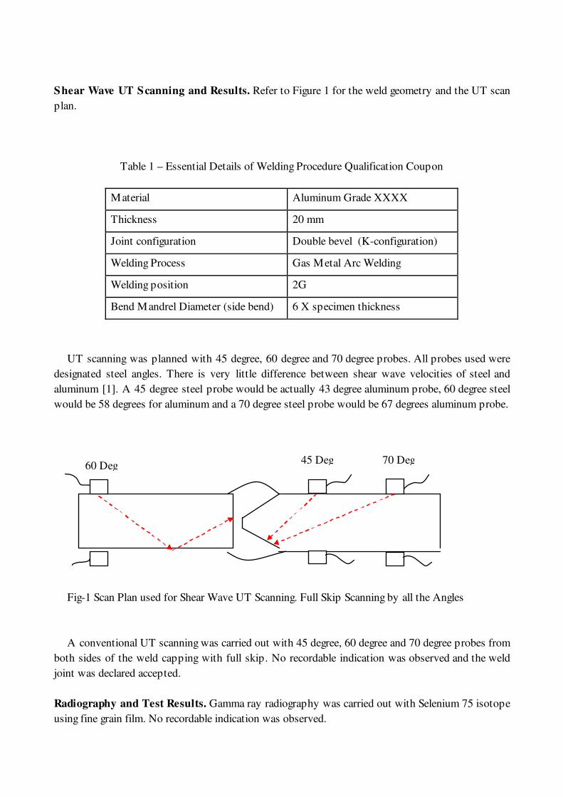
Shear Wave UT Scanning and Results. Refer to Figure 1 for the weld geometry and the UT scan
plan.
Table 1 – Essential Details of Welding Procedure Qualification Coupon
Material Aluminum Grade XXXX
Thickness 20 mm
Joint configuration Double bevel (K-configuration)
Welding Process Gas Metal Arc Welding
Welding position 2G
Bend Mandrel Diameter (side bend) 6 X specimen thickness
UT scanning was planned with 45 degree, 60 degree and 70 degree probes. All probes used were
designated steel angles. There is very little difference between shear wave velocities of steel and
aluminum [1]. A 45 degree steel probe would be actually 43 degree aluminum probe, 60 degree steel
would be 58 degrees for aluminum and a 70 degree steel probe would be 67 degrees aluminum probe.
Fig-1 Scan Plan used for Shear Wave UT Scanning. Full Skip Scanning by all the Angles
A conventional UT scanning was carried out with 45 degree, 60 degree and 70 degree probes from
both sides of the weld capping with full skip. No recordable indication was observed and the weld
joint was declared accepted.
Radiography and Test Results. Gamma ray radiography was carried out with Selenium 75 isotope
using fine grain film. No recordable indication was observed.
60 Deg 45 Deg 70 Deg
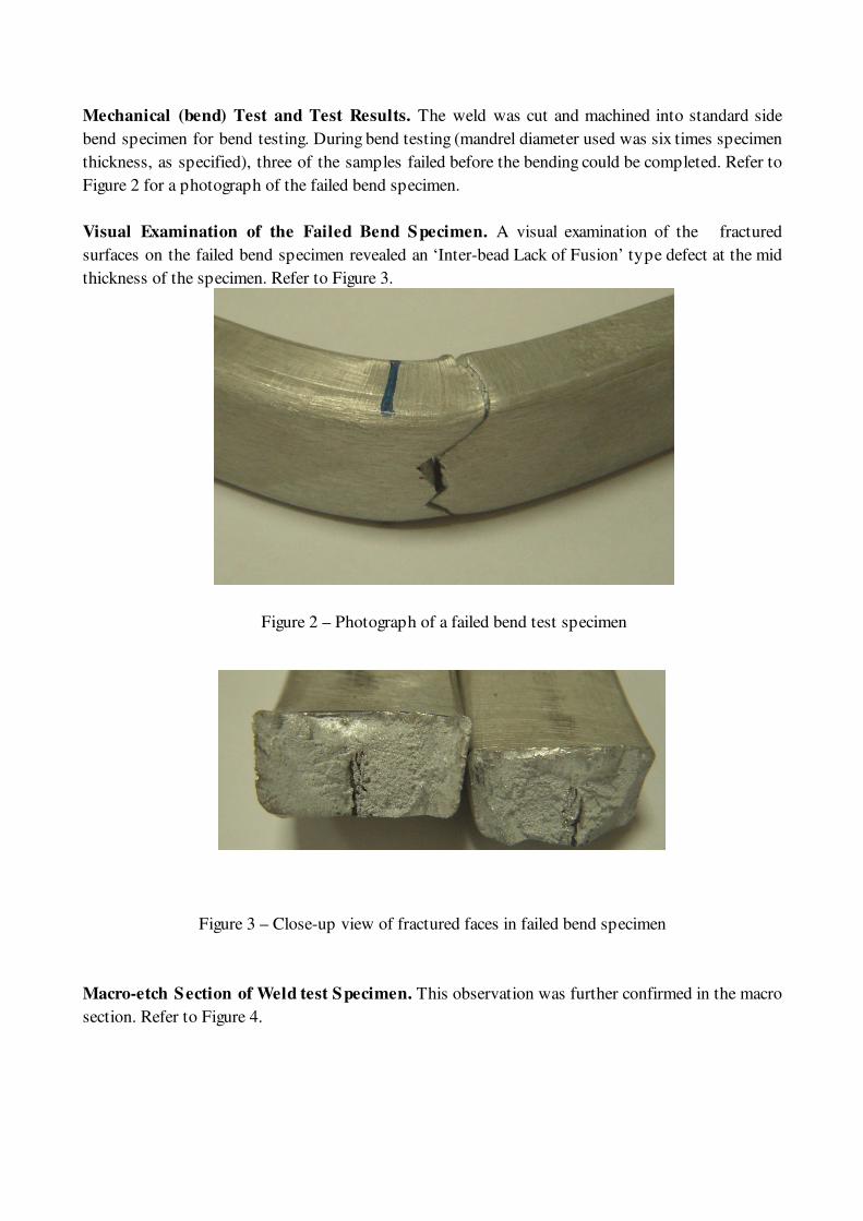
Mechanical (bend) Test and Test Results. The weld was cut and machined into standard side
bend specimen for bend testing. During bend testing (mandrel diameter used was six times specimen
thickness, as specified), three of the samples failed before the bending could be completed. Refer to
Figure 2 for a photograph of the failed bend specimen.
Visual Examination of the Failed Bend Specimen. A visual examination of the fractured
surfaces on the failed bend specimen revealed an ‘Inter-bead Lack of Fusion’ type defect at the mid
thickness of the specimen. Refer to Figure 3.
Figure 2 – Photograph of a failed bend test specimen
Figure 3 – Close-up view of fractured faces in failed bend specimen
Macro-etch Section of Weld test Specimen. This observation was further confirmed in the macro
section. Refer to Figure 4.
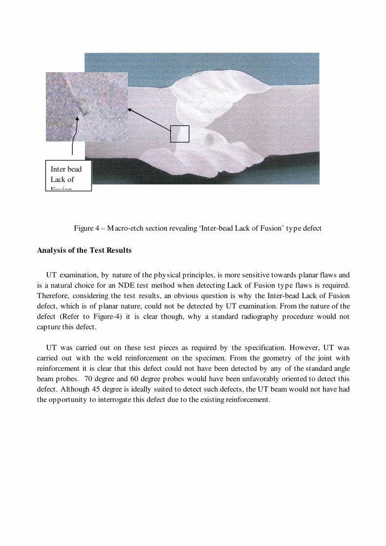
Figure 4 – Macro-etch section revealing ‘Inter-bead Lack of Fusion’ type defect
Analysis of the Test Results
UT examination, by nature of the physical principles, is more sensitive towards planar flaws and
is a natural choice for an NDE test method when detecting Lack of Fusion type flaws is required.
Therefore, considering the test results, an obvious question is why the Inter-bead Lack of Fusion
defect, which is of planar nature, could not be detected by UT examination. From the nature of the
defect (Refer to Figure-4) it is clear though, why a standard radiography procedure would not
capture this defect.
UT was carried out on these test pieces as required by the specification. However, UT was
carried out with the weld reinforcement on the specimen. From the geometry of the joint with
reinforcement it is clear that this defect could not have been detected by any of the standard angle
beam probes. 70 degree and 60 degree probes would have been unfavorably oriented to detect this
defect. Although 45 degree is ideally suited to detect such defects, the UT beam would not have had
the opportunity to interrogate this defect due to the existing reinforcement.
Inter bead
Lack of
Fusion
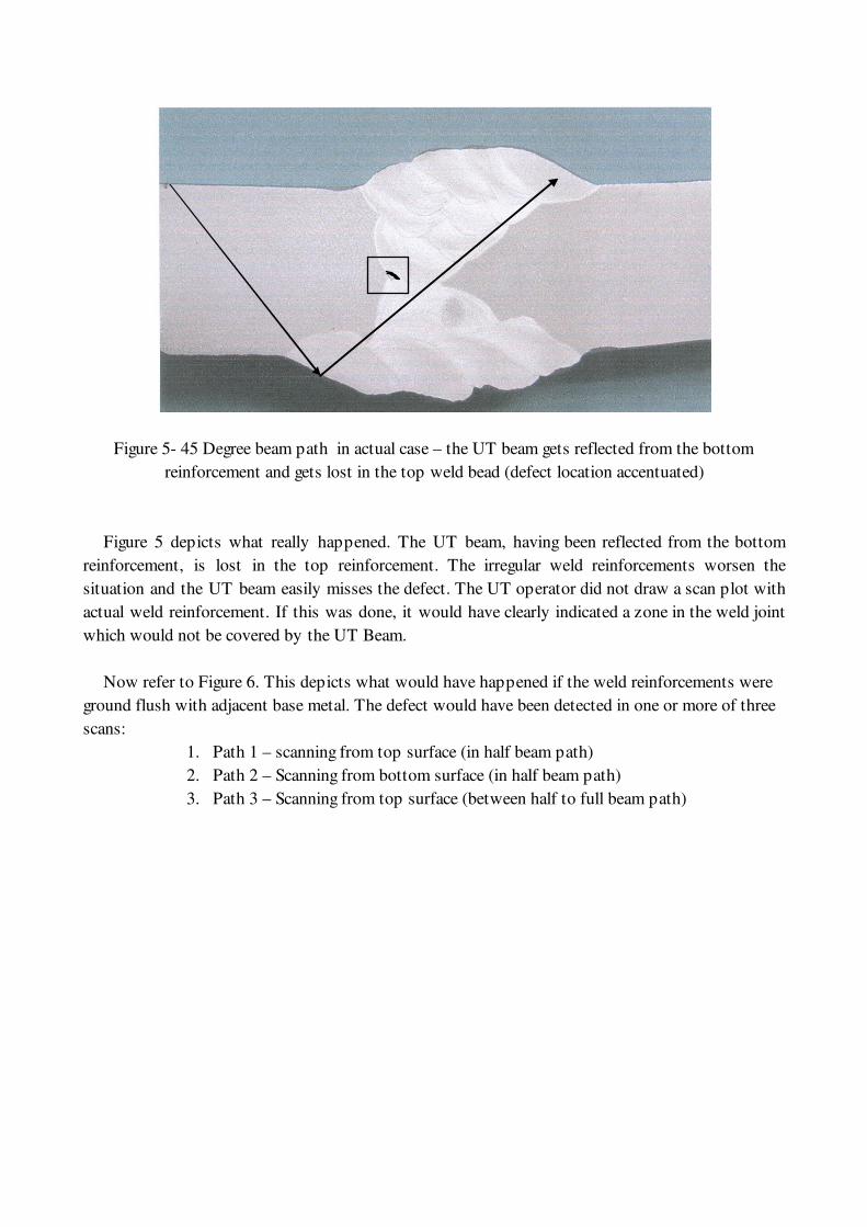
Figure 5- 45 Degree beam path in actual case – the UT beam gets reflected from the bottom
reinforcement and gets lost in the top weld bead (defect location accentuated)
Figure 5 depicts what really happened. The UT beam, having been reflected from the bottom
reinforcement, is lost in the top reinforcement. The irregular weld reinforcements worsen the
situation and the UT beam easily misses the defect. The UT operator did not draw a scan plot with
actual weld reinforcement. If this was done, it would have clearly indicated a zone in the weld joint
which would not be covered by the UT Beam.
Now refer to Figure 6. This depicts what would have happened if the weld reinforcements were
ground flush with adjacent base metal. The defect would have been detected in one or more of three
scans:
1. Path 1 – scanning from top surface (in half beam path)
2. Path 2 – Scanning from bottom surface (in half beam path)
3. Path 3 – Scanning from top surface (between half to full beam path)
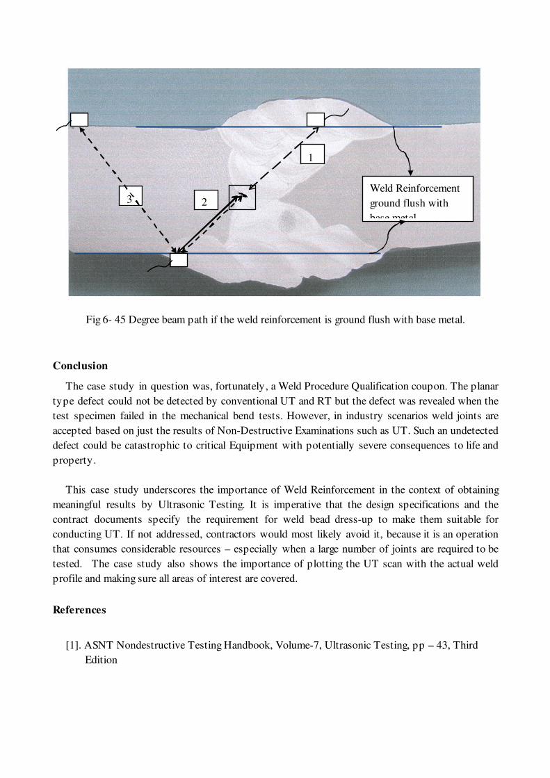
Fig 6- 45 Degree beam path if the weld reinforcement is ground flush with base metal.
Conclusion
The case study in question was, fortunately, a Weld Procedure Qualification coupon. The planar
type defect could not be detected by conventional UT and RT but the defect was revealed when the
test specimen failed in the mechanical bend tests. However, in industry scenarios weld joints are
accepted based on just the results of Non-Destructive Examinations such as UT. Such an undetected
defect could be catastrophic to critical Equipment with potentially severe consequences to life and
property.
This case study underscores the importance of Weld Reinforcement in the context of obtaining
meaningful results by Ultrasonic Testing. It is imperative that the design specifications and the
contract documents specify the requirement for weld bead dress-up to make them suitable for
conducting UT. If not addressed, contractors would most likely avoid it, because it is an operation
that consumes considerable resources – especially when a large number of joints are required to be
tested. The case study also shows the importance of plotting the UT scan with the actual weld
profile and making sure all areas of interest are covered.
References
[1]. ASNT Nondestructive Testing Handbook, Volume-7, Ultrasonic Testing, pp – 43, Third
Edition
1
2 3 Weld Reinforcement
ground flush with
base metal