Embed Size (px)
Citation preview

www.eaton.eu
Panel Building Accessories Panel Building Accessories
Catalogue 2015Catalogue 2015
PIFTPIFT
Plug In Fused TerminalPlug In Fused Terminal
Fuse DisconnectorsFuse Disconnectors
TerminalsTerminals
Filters and FansFilters and Fans
Electrical Cabinet HeatingElectrical Cabinet Heating
ThermostatsThermostats

We deliver:• Electrical solutions that use less energy, improve power reliability
and make the places we live and work safer and more comfortable
• Hydraulic and electrical solutions that enable machines to deliver more productivity without wasting power
• Aerospace solutions that make aircraft lighter, safer and less costly to operate, and help airports operate more efficiently
• Vehicle drivetrain and powertrain solutions that deliver more power to cars, trucks and buses, while reducing fuel consumption and emissions
Discover today’s Eaton.
Powering business worldwide
As a global power management company, we help customers worldwide manage the power needed for buildings, aircraft, trucks, cars, machinery and businesses.
Eaton’s innovative technologies help customers manage electrical, hydraulic and mechanical power more reliably, efficiently, safely and sustainably.
We provide integrated solutions that help make energy, in all its forms, more practical and accessible.
With 2014 sales of $22.6 billion, Eaton has approximately 100,000 employees around the world and sells products in more than 175 countries.
Eaton.com
Energizing a worldthat demands more.

1 EATON CORPORATION CA008008EN
Fuse Switch Disconnectors XNH…
• For fuse links NH000 to NH3
• Rated operating current of 160, 250, 400 and 630A
• Sizes 00, 1, 2 and 3
• Degree of protection IP2XC
• Frame widths of 106, 184, 210 and 250 mm
• For mounting plate, DIN rail and busbar system of 60 mm
• System size 195 and 300 mm
• Can be locked with a pad lock
• Current-theft protection
• Flex-System for cable connection at the top/bottom
• Improved operator safety
• Flat connection for cable lug, box terminal, clamp-type terminal,
prism terminal and double prism terminal
• Switch cover with safety parking position
• Fuse monitoring light with LED on the device
• Electronic fuse monitoring
• SmartWire-DT® option
Fuse Switch Disconnectors XNH...
vt61615
vt64215
vt64015
vt61715

2 EATON CORPORATION CA008008EN
Fuse Switch Disconnectors XNH…
Fuse Switch Disconnectors XNH…
Size Type of connection Ie (A) Type Article No. Pack designation (pcs.)
• Degree of protection IP2XC in operating mode• According to IEC/EN 60947-3• AC 690 V / DC 440 V• Conditional rated short-circuit current 120kA (500V) and 100kA (690V)• Reaction to fire according to UL 94, self-extinguishing• Current paths of electrolytic copper, silver-plated• For fixing on mounting plates and DIN rails
Basic3-pole for mounting plate
00 Flat connection M8 max. 95 mm² 160 XNH00-A160 183025 1Box terminal 1.5 - 95 mm² 160 XNH00-A160-BT 183026 1
1 Flat connection M10 max. 150 mm² 250 XNH1-A250 183043 1Box terminal 35 - 150 mm² 250 XNH1-A250-BT 183044 1
2 Flat connection M10 max. 240 mm² 400 XNH2-A400 183057 1Box terminal 95 - 300 mm² 400 XNH2-A400-BT 183058 1
3 Flat connection M10 max. 300 mm² 630 XNH3-A630 183071 1Box terminal 95 - 300 mm² 630 XNH3-A630-BT 183072 1
Fuse Control Light3-pole for mounting plate
00 Flat connection M8 max. 95 mm² 160 XNH00-FCL-A160 183027 1Box terminal 1.5 - 95 mm² 160 XNH00-FCL-A160-BT 183028 1
1 Flat connection M10 max. 150 mm² 250 XNH1-FCL-A250 183045 1Box terminal 35 - 150 mm² 250 XNH1-FCL-A250-BT 183046 1
2 Flat connection M10 max. 240 mm² 400 XNH2-FCL-A400 183059 1Box terminal 95 - 300 mm² 400 XNH2-FCL-A400-BT 183060 1
3 Flat connection M10 max. 300 mm² 630 XNH3-FCL-A630 183073 1Box terminal 95 - 300 mm² 630 XNH3-FCL-A630-BT 183074 1
Fuse Control FCE3-pole for mounting plate
00 Flat connection M8 max. 95 mm² 160 XNH00-FCE-A160 183029 1Box terminal 1.5 - 95 mm² 160 XNH00-FCE-A160-BT 183030 1
1 Flat connection M10 max. 150 mm² 250 XNH1-FCE-A250 183047 1Box terminal 35 - 150 mm² 250 XNH1-FCE-A250-BT 183048 1
2 Flat connection M10 max. 240 mm² 400 XNH2-FCE-A400 183061 1Box terminal 95 - 300 mm² 400 XNH2-FCE-A400-BT 183062 1
3 Flat connection M10 max. 300 mm² 630 XNH3-FCE-A630 183075 1Box terminal 95 - 300 mm² 630 XNH3-FCE-A630-BT 183076 1
1-pole for mounting plate
00 Flat connection M8 max. 95 mm² 160 XNH00-1-A160 183031 1Box terminal 1.5 - 95 mm² 160 XNH00-1-A160-BT 183032 1
1 Flat connection M10 max. 150 mm² 250 XNH1-1-A250 183049 1Box terminal 35 - 150 mm² 250 XNH1-1-A250-BT 183050 1
3 Flat connection M10 max. 300 mm² 400/630 XNH32-1-A630 183063 1Box terminal 95 - 300 mm² 400/630 XNH32-1-A630-BT 183064 1
vt61615
wa_vt15515
vt64015

3 EATON CORPORATION CA008008EN
Fuse Switch Disconnectors XNH…
Fuse Switch Disconnectors XNH…
Size Type of connection Ie (A) Type Article No. Pack designation (pcs.)
• Degree of protection IP2XC in operating mode• According to IEC/EN 60947-3• AC 690 V / DC 440 V• Conditional rated short-circuit current 120kA (500V) and 100kA (690V)• Reaction to fire according to UL 94, self-extinguishing• Current paths of electrolytic copper, silver-plated• For fixing on busbars of 60mm (SASY 60i)• Cable connection optionally at the top or bottom
Basic3-pole for SASY 60i
00 Flat connection M8 max. 95 mm² 160 XNH00-S160 183033 1Box terminal 1.5 - 95 mm² 160 XNH00-S160-BT1 183034 1Box terminal 1.5 - 95 mm² 160 XNH00-S160-BT2 183035 1
1 Flat connection M10 max. 150 mm² 250 XNH1-S250 183051 1Box terminal 35 - 150 mm² 250 XNH1-S250-BT 183052 1
2 Flat connection M10 max. 240 mm² 400 XNH2-S400 183065 1Box terminal 95 - 300 mm² 400 XNH2-S400-BT 183066 1
3 Flat connection M10 max. 300 mm² 630 XNH3-S630 183077 1Box terminal 95 - 300 mm² 630 XNH3-S630-BT 183078 1
Fuse Control Light3-pole for SASY 60i
00 Flat connection M8 max. 95 mm² 160 XNH00-FCL-S160 183036 1Box terminal 1.5 - 95 mm² 160 XNH00-FCL-S160-BT1 183037 1Box terminal 1.5 - 95 mm² 160 XNH00-FCL-S160-BT2 183038 1
1 Flat connection M10 max. 150 mm² 250 XNH1-FCL-S250 183053 1Box terminal 35 - 150 mm² 250 XNH1-FCL-S250-BT 183054 1
2 Flat connection M10 max. 240 mm² 400 XNH2-FCL-S400 183067 1Box terminal 95 - 300 mm² 400 XNH2-FCL-S400-BT 183068 1
3 Flat connection M10 max. 300 mm² 630 XNH3-FCL-S630 183079 1Box terminal 95 - 300 mm² 630 XNH3-FCL-S630-BT 183080 1
Fuse Control FCE3-pole for SASY 60i
00 Flat connection M8 max. 95 mm² 160 XNH00-FCE-S160 183039 1Box terminal 1.5 - 95 mm² 160 XNH00-FCE-S160-BT1 183040 1Box terminal 1.5 - 95 mm² 160 XNH00-FCE-S160-BT2 183041 1
1 Flat connection M10 max. 150 mm² 250 XNH1-FCE-S250 183055 1Box terminal 35 - 150 mm² 250 XNH1-FCE-S250-BT 183056 1
2 Flat connection M10 max. 240 mm² 400 XNH2-FCE-S400 183069 1Box terminal 95 - 300 mm² 400 XNH2-FCE-S400-BT 183070 1
3 Flat connection M10 max. 300 mm² 630 XNH3-FCE-S630 183081 1Box terminal 95 - 300 mm² 630 XNH3-FCE-S630-BT 183082 1
1-pole for SASY 60i
00 Flat connection M8 max. 95 mm² 160 XNH00-1-S160 183042 1
vt61915
wa_vt14215
vt64215

4 EATON CORPORATION CA008008EN
Fuse Switch Disconnectors XNH…
Basic module with 2 digital inputs for 00 with FCE XNH00-SWD-KIT 183083 1switch position indication and trip 1 with FCE XNH1-SWD-KIT 183084 1signal. Complete set for direct 2 with FCE XNH2-SWD-KIT 183085 1mounting at the switchgear. 3 with FCE XNH3-SWD-KIT 183086 1Basic module with 2 digital inputs for 00 with FCE XNH00-SWD-KIT-EXT 183087 1switch position indication and trip 1/2/3 with FCE XNH123-SWD-KIT-EXT 183088 1signal. For fixing on the mounting plate.
Description Suitable Type Article No. Packfor size designation (pcs.)
SmartWire-DT®, Basic Module Kit• Kit consisting of SWD module, ready-made cables and additional cover for cable area• Only in connection with Fuse Control FCE
Basic module with 2 digital inputs 00/1/2/3 XNH-SWD-2DX-1 183089 1with FCE
Advanced module with 2 digital and 3 00/1/2/3 XNH-SWD-2DX-3AX-1 183090 1analogue inputs with FCE
Description Suitable Type Article No. Packfor size designation (pcs.)
SmartWire-DT®, Modules
Cable entries can be knocked out as 00 XNH00-XKSA-36 183091 2required. 36, 42 and 66 mm length for 00 XNH00-XKSA-66 183092 2top and bottom. Multiple use per 1 XNH1-XKSA-42 183093 2device is possible. 2 XNH2-XKSA-42 183094 2
3 XNH3-XKSA-42 183095 2
Description Suitable Type Article No. Packfor size designation (pcs.)
Cover for connection area, 3-pole
Can be fixed at the top or bottom of 00 XNH00-XKSV-39-34 183096 2 the device. 32 or 39 and 34 mm distance 00 XNH00-XKSV-32 183097 2to the base plate.
Description Suitable Type Article No. Packfor size designation (pcs)
Extension for cover of connection area, 3-pole for SASY 60i
Cable entries can be knocked out as 00 XNH00-1-XKSA-36 184585 2required. 36, 42 and 66 mm length for 00 XNH00-1-XKSA-66 184586 2top and bottom. Multiple use per 1 XNH1-1-XKSA-42 184587 2device is possible. 3 (2) XNH3-1-XKSA-42 184588 2
Description Suitable Type Article No. Packfor size designation (pcs.)
Cover for connection area, 1-pole

5 EATON CORPORATION CA008008EN
Fuse Switch Disconnectors XNH…
For flat connection or box terminal 00 XNH00-XKSS-39-34 183098 200 XNH00-XKSS-32 183099 2
For BT2 box terminal 00 XNH00-XKSS-BT-39-34 183100 200 XNH00-XKSS-BT-32 183101 2
For flat connection or box terminal 1 XNH1-XKSS-39-34 183102 21 XNH1-XKSS-32 183103 22 XNH2-XKSS-39-34 183104 22 XNH2-XKSS-32 183105 23 XNH3-XKSS-39-34 183106 23 XNH3-XKSS-32 183107 2
Description Suitable Type Article No. Packfor size designation (pcs.)
Reach-over protection, 3-pole for SASY 60i• Can be fixed at the top or bottom of the device• For 32 or 39 and 34mm distance to the base plate
Compensation adapter top/bottom 00 XNH00-XHAA-T/B 183108 2Level 70 => 90mmSide compensation profiles 00 XNH00-XHAA-R/L 183109 2Level 70 => 90mm
vt67015
Description Suitable Type Article No. Packfor size designation (pcs.)
Height compensation adapter 20mm, 3-pole
Top and bottom 00 XNH00-XCS-T/B 183110 2Level 60, 70 mmSide 00 XNH00-XCS-R/L 183111 2Level 32, 60, 70 mmTop and bottom, side 1, 2, 3 XNH123-XCS 183112 2Level 32, 60, 70 mm
Description Suitable Type Article No. Packfor size designation (pcs.)
Cover supports
For manipulation-protected 00, 1, 2, 3 XNH-XSECUR 183113 1 setblocking of the inspection window
Note: 1 set includes current-theft protection for a 3-pole XNH.
Description Suitable Type Article No. Packfor size designation (pcs.)
Current-theft protection
For mounting XNH disconnectors 00 XNH00-XRAIL 183114 1on 2x DIN rails EN 50022
1 XNH1-XRAIL 183115 1
vt68115
Description Suitable Type Article No. Packfor size designation (pcs.)
DIN-rail fastener

6 EATON CORPORATION CA008008EN
Fuse Switch Disconnectors XNH…
For locking with a padlock 00, 1, 2, 3 XNH-XLOCK 182993 1when using a closed XNH disconnector
Note: Padlock with a shackle diameter of 6mm max.
Description Suitable Type Article No. Packfor size designation (pcs.)
Locking device
Tool-requiring lock of internal 00, 1, 2, 3 XNH-XLATCH 182992 1contact protection covers
Description Suitable Type Article No. Packfor size designation (pcs.)
Internal lock for contact-protection
1 change-over contact, AC 250V, 10/3A 00 XNH00-XPOS 182995 1
1, 2, 3 XNH123-XPOS 182996 1
vt67815
Description Suitable Type Article No. Packfor size designation (pcs.)
Switch position indicator
1 change-over contact, AC 250V, 10/3A 00 XNH00-XMFM 182997 3
1, 2, 3 XNH123-XMFM 182998 3
Note: Only in combination with NH fuse links equipped with a striker pin. Not for use in combination with box terminal or double-prism terminals.
vt67915
Description Suitable Type Article No. Packfor size designation (pcs.)
Mechanical fuse monitoring
To mechanically connect 00, 1, 3/(2) XNH-XLINK 182999 12x 1-pole or 3-pole+ 1-poleXNH disconnectors
Description Suitable Type Article No. Packfor size designation (pcs.)
Conncection kit, 2 and 4 poles
wa_vt15815

7 EATON CORPORATION CA008008EN
Fuse Switch Disconnectors XNH…
Clamp-type terminal1.5 - 50 mm², Cu 00 XNH00-XCT 183002 325 - 150 mm², Cu 1 XNH1-XCT 183003 325 - 240 mm², Cu 2 XNH2-XCT 183004 3CU-BAND-11x21x1 3 XNH3-XCT 183005 3
vt68215
Description Suitable Type Article No. Packfor size designation (pcs.)
Connection technology
Prism terminal10 - 70 mm², Cu/Al 00 XNH00-XPRC 183006 370 - 150 mm², Cu/Al 1 XNH1-XPRC 183007 3120 - 240 mm², Cu/Al 2 XNH2-XPRC 183008 3120 - 300 mm², Cu/Al 3 XNH3-XPRC 183009 3
vt67515
Double-prism terminal 2 x 70 - 95 mm², Cu/Al 1 XNH1-X2PRC 183010 32 x 120 - 150 mm², Cu/Al 2 XNH2-X2PRC 183011 32 x 120 - 240 mm², Cu/Al 3 XNH3-X2PRC 183012 3
vt67315
Box terminal 35 - 150 mm², Cu/Al 1 XNH1-BT 183000 395 - 300 mm², Cu/Al 2, 3 XNH23-BT 183001 3
Note: Box terminal and double-prism terminal not for use in combination with mechanical fuse monitoring XNH…-XMFM.
vt68615
Cover for XNH disconnector Basic 00 XNH00-XGRIP 183013 11 XNH1-XGRIP 183014 12 XNH2-XGRIP 183015 13 XNH3-XGRIP 183016 1
Description Suitable Type Article No. Packfor size designation (pcs.)
Spare handle cover, 3-pole
Cover for XNH disconnector with 00 XNH00-XGRIP-FCL 183017 1Fuse Control FCL 1 XNH1-XGRIP-FCL 183018 1
2 XNH2-XGRIP-FCL 183019 13 XNH3-XGRIP-FCL 183020 1
Cover for XNH disconnector with 00 XNH00-XGRIP-FCE 183021 1Fuse Control FCE 1 XNH1-XGRIP-FCE 183022 1
2 XNH2-XGRIP-FCE 183023 13 XNH3-XGRIP-FCE 183024 1
Note: FCL and FCE can only be used with fuse links equipped with live handle straps.
For XNH disconnector Basic, FCL, FCE 1, 2, 3 XNH-XARC 182994 1
Note: 1 set includes extinguishing chambers for a 3-pole XNH disconnector.
Description Suitable Type Article No. Packfor size designation (pcs.)
Spare extinguishing chambers, 3-pole

8 EATON CORPORATION CA008008EN
Fuse Switch Disconnectors XNH…
Technical Data
XNH00…-A160… XNH00…-S160… XNH1…-A250… XNH1…-S250…
Standard IEC/EN 60947-3 IEC/EN 60947-3 IEC/EN 60947-3 IEC/EN 60947-3
NH fuses 1) according to DIN VDE 0636-2 000 / 00 000 / 00 1 1Rated operating voltage Ue V AC 690, DC 440 AC 690, DC 440 AC 690, DC 440 AC 690, DC 440Rated operating current Ie A 160 160 250 250Rated frequency f Hz 40 - 60 40 - 60 40 - 60 40 - 60Rated insulation voltage Ui V AC 800 AC 800 AC 800 AC 800Total power loss at Ith (without fuses) Pv W 9 14 16 22Power loss at 80% (without fuses) Pv W 5,8 9 10,2 14,1Rated impulse withstand voltage Uimp kV 8 8 8 8Utilization category AC-23B (400V/160A) AC-23B (400V/160A) AC-23B (400V/250A) AC-23B (400V/250A) AC-22B (500V/160A) AC-22B (500V/160A) AC-22B (500V/250A) AC-22B (500V/250A) AC-21B (690V/160A) AC-21B (690V/160A) AC-21B (690V/250A) AC-21B (690V/250A) DC-22B (250V/160A) DC-22B (250V/160A) DC values on DC values on DC-21B (440V/160A) DC-21B (440V/160A) request requestConditional rated short-circuit current kA 120 (500V) 120 (500V) 120 (500V) 120 (500V) 100 (690V) 100 (690V) 100 (690V) 100 (690V)Rated short-time withstand current Icw kA 7 7 10 10Max. permitted power loss per fuse link PNH W 12 12 23 23Degree of protection - front (XNH installed) Operating status IP20 Operating status IP20 Operating status IP20 Operating status IP20 Contact prot. IP2XC Contact prot. IP2XC Contact prot. IP2XC Contact prot. IP2XC Handle cover open IP10 Handle cover open IP10 Handle cover open IP10 Handle cover open IP10Ambient temperature T35 °C -25 bis +55 -25 bis +55 -25 bis +55 -25 bis +55Rated operating mode Permanent operation Permanent operation Permanent operation Permanent operationActivation Dependent Dependent Dependent Dependent manual activation manual activation manual activation manual activationPosition Vertical/horizontal Vertical/horizontal Vertical/horizontal Vertical/horizontalAltitude m max. 2000 max. 2000 max. 2000 max. 2000Degree of pollution 3 3 3 3Overvoltage category III III III IIIColour Grey Grey Grey GreyRoHs Yes Yes Yes YesEnergy feeder direction Any Any (FLEX System) Any Any (FLEX System)Lockable Yes, optional Yes, optional Yes, optional Yes, optionalSealable Yes, standard Yes, standard Yes, standard Yes, standardMaterial Polyamide Polyamide Polyamide PolyamideReaction to fire Self-extinguishing Self-extinguishing Self-extinguishing Self-extinguishing acc. to UL94 acc. to UL94 acc. to UL94 nach UL94Halogen-free Yes Yes Yes YesVoltage test Yes, sliding in- Yes, sliding in- Yes, sliding in- Yes, sliding in- spection windows spection windows spection windows spection windowsElectrical service life (operating cycles) 300 300 200 200Mechanical service life (operating cycles) 1400 1400 1400 1400Track resistance CTI 600 CTI 600 CTI 600 CTI 600Temperature resistance up to °C 125 125 125 125Terminal capacities: Flat connection Bolt diameter M8 M8 M10 M10 Cable lug max. width mm 25 25 37 37 Flat rail mm 20x10 20x10 30x10 30x10 Box terminal multi-wire mm² 1.5 - 95 Cu 1.5 - 95 Cu 35 - 150 Cu/Al 35 - 150 Cu/Al Cu-Band 6x9x0.8 6x9x0.8 on request on request Clamp-type terminal multi-wire mm² 1.5 - 50 Cu 1.5 - 50 Cu 25 - 150 Cu 25 - 150 Cu Cu-Band 6x9x0.8 6x9x0.8 6x16x0.8 6x16x0.8 Prism terminal multi-wire mm² 10 - 70 Cu/Al 10 - 70 Cu/Al 10 - 150 Cu/Al 10 - 150 Cu/Al Double-prism terminal multi-wire mm² - - 2x (70 - 95) Cu/Al 2x (70 - 95) Cu/Al
Note: Please leave a minimum distance to grounded live parts: Side = 20 mm, top = 50 mm. Exception DC-21B: Side = 50 mm, top = 100 mm (valid for XNH00…).1) Type-tested with NH fuse links of characteristic gG. Safety control FCE and FCL only in combination with NH fuses equipped with live handle straps.

9 EATON CORPORATION CA008008EN
Fuse Switch Disconnectors XNH…
Technical Data
XNH2…-A400… XNH2…-S400… XNH3…-A630… XNH3…-S630…
Standard IEC/EN 60947-3 IEC/EN 60947-3 IEC/EN 60947-3 IEC/EN 60947-3
NH fuses 1) acc. to DIN VDE 0636-2 2 2 3 / 2 3 / 2Rated operating voltage Ue V AC 690, DC 440 AC 690, DC 440 AC 690, DC 440 AC 690, DC 440Rated operating current Ie A 400 400 630 630Rated frequency f Hz 40 - 60 40 - 60 40 - 60 40 - 60Rated insulation voltage Ui V AC 800 AC 800 AC 800 AC 800Total power loss at Ith (without fuses) Pv W 22 22 on request on requestPower loss at 80% (without fuses) Pv W 14.1 14.1 on request on requestRated impulse withstand voltage Uimp kV 8 8 8 8Utilization category AC-23B (400V/400A) AC-23B (400V/400A) AC-23B (400V/630A) AC-23B (400V/630A) AC-22B (500V/400A) AC-22B (500V/400A) AC-22B (500V/630A) AC-22B (500V/630A) AC-21B (690V/400A) AC-21B (690V/400A) AC-21B (690V/630A) AC-21B (690V/630A) DC values on DC values on DC values on DC values on request request request requestConditional rated short-circuit current kA 120 (500V) 120 (500V) 120 (500V) 120 (500V) 100 (690V) 100 (690V) 100 (690V) 100 (690V)Rated short-time withstand current Icw kA 10 10 10 10Max. permitted power loss per fuse link PNH W 34 34 48 48Degree of protection - front (XNH installed) Operating status IP20 Operating status IP20 Operating status IP20 Operating status IP20 Contact prot. IP2XC Contact prot. IP2XC Contact prot. IP2XC Contact prot. IP2XC Handle cover open IP10 Handle cover open IP10 Handle cover open IP10 Handle cover open IP10Ambient temperature T35 °C -25 to +55 -25 to +55 -25 to +55 -25 to +55Rated operating mode Permanent operation Permanent operation Permanent operation Permanent operationActivation Dependent Dependent Dependent Dependent manual activation manual activation manual activation manual activationPosition Vertical/horizontal Vertical/horizontal Vertical/horizontal Vertical/horizontalAltitude m max. 2000 max. 2000 max. 2000 max. 2000Degree of pollution 3 3 3 3Overvoltage category III III III IIIColour Grey Grey Grey GreyRoHs Yes Yes Yes YesEnergy feeder direction Any Any (FLEX System) Any Any (FLEX System)Lockable Yes, optional Yes, optional Yes, optional Yes, optionalSealable Yes, standard Yes, standard Yes, standard Yes, standardMaterial Polyamide Polyamide Polyamide PolyamideReaction to fire Self-extinguishing Self-extinguishing Self-extinguishing Self-extinguishing acc. to UL94 acc. to UL94 acc. to UL94 acc. to UL94Halogen-free Yes Yes Yes Yes Voltage test Yes, sliding in- Yes, sliding in- Yes, sliding in- Yes, sliding in- spection windows spection windows spection windows spection windowsElectrical service life (operating cycles) 200 200 200 200Mechanical service life (operating cycles) 800 800 800 800Track resistance CTI 600 CTI 600 CTI 600 CTI 600Temperature resistance up to °C 125 125 125 125Terminal capacities: Flat connection Bolt diameter M10 M10 M10 M10 Cable lug max. width mm 48 48 56 56 Flat rail mm 40x10 40x10 50x10 50x10 Box terminal multi-wire mm² 95 - 300 Cu/Al 95 - 300 Cu/Al 95 - 300 Cu/Al 95 - 300 Cu/Al Cu-Band on request on request on request on request Clamp-type terminal multi-wire mm² 25 - 240 Cu 25 - 240 Cu on request on request Cu-Band 10x16x0.8 10x16x0.8 11x21x1 11x21x1 Prism terminal multi-wire mm² 120 - 240 Cu/Al 120 - 240 Cu/Al 120 - 300 Cu/Al 120 - 300 Cu/Al Double-prism terminal multi-wire mm² 2x (120 - 150) Cu/Al 2x (120 - 150) Cu/Al 2x (120 - 240) Cu/Al 2x (120 - 240) Cu/Al
Note: Please leave a minimum distance to grounded live parts: Side = 20 mm, top = 50 mm. 1) Type-tested with NH fuse links of characteristic gG. Safety control FCE and FCL only in combination with NH fuses equipped with live handle straps.
10 EATON CORPORATION CA008008EN
Fuse Switch Disconnectors XNH…
Technical Data
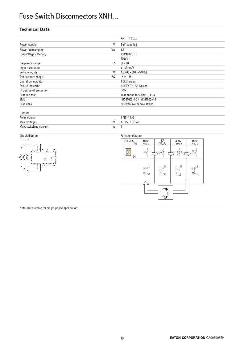
XNH…FCE…
Power supply V Self-supplied
Power consumption VA 1.5Overvoltage category 230/400V : III 500V : IIFrequency range HZ 50 - 60Input resistance >1 kOhm/VVoltage inputs V AC 400 - 500 (+/-10%)Temperature range °C -5 to +55Operation indicator 1 LED greenFailure indicator 3 LEDs (F1, F2, F3) redIP degree of protection IP3XFunction test Test button for relay + LEDsEMC IEC 61000-4-5 / IEC 61000-4-4Fuse links NH with live handle straps
Outputs Relay output 1 NC, 1 NOMax. voltage V AC 250 / DC 24Max. switching current A 1
Circuit diagram Function diagram
Note: Not suitable for single-phase application!

11 EATON CORPORATION CA008008EN
Fuse Switch Disconnectors XNH…
Dimensional drawings
XNH00-A160
Fixing dimensions:
Mas_XNH00-A160
top

12 EATON CORPORATION CA008008EN
Fuse Switch Disconnectors XNH…
Dimensional drawings
XNH00-FCE-A160
Fixing dimensions:
Mas_XNH00-FCE-A160
top

13 EATON CORPORATION CA008008EN
Fuse Switch Disconnectors XNH…
Dimensional drawings
XNH1-A250, XNH2-A400, XNH3-A630
Fixing dimensions in mm:
Mas_XNH1-A250
Type a b c e f g h1 h2 h3 i k l p q r s t1 t2 u
XNH1-A250 184 298 306 117 185 46 70 32 - 25 58 Ø10,5 4 19 138 5 272 - -XNH2-A400 210 298 306 134 205 36 90 32 70 26 66 Ø14 4 19 138 10 268 288 5XNH3-A630 250 298 306 143 205 36 90 32 70 26 82 Ø14 4 19 138 10 268 288 5
Type a c r v w x y
XNH1-A250 184 306 138 150 50 25 11XNH2-A400 210 306 138 166 50 0 11XNH3-A630 250 306 138 195 50 0 13
top

14 EATON CORPORATION CA008008EN
Fuse Switch Disconnectors XNH…
Dimensional drawings
XNH1-FCE-A250, XNH2-FCE-A400, XNH3-FCE-A630
Fixing dimensions in mm:
Mas_XNH1-FCE-A250
Type a b c d e f g h1 h2 h3 i k l p q r s t1 t2 u
XNH1-FCE-A250 184 298 306 148 117 185 46 70 32 - 25 58 Ø10,5 4 19 138 5 272 - -XNH2-FCE-A400 210 298 306 165 134 205 36 90 32 70 26 66 Ø14 4 19 138 10 268 288 5XNH3-FCE-A630 250 298 306 173 143 205 36 90 32 70 26 82 Ø14 4 19 138 10 268 288 5
Type a c r v w x y
XNH1-FCE-A250 184 306 138 150 50 25 11XNH2-FCE-A400 210 306 138 166 50 0 11XNH3-FCE-A630 250 306 138 195 50 0 13
top

15 EATON CORPORATION CA008008EN
Fuse Switch Disconnectors XNH…
Dimensional drawings
XNH00-S160
Outgoing - top (Ao)
Mas_XNH00-S160
Outgoing - bottom (Au)
5 or 10

16 EATON CORPORATION CA008008EN
Fuse Switch Disconnectors XNH…
Dimensional drawings
XNH00-FCE-S160
Mas_XNH00-FCE-S160
5 or 10

17 EATON CORPORATION CA008008EN
Fuse Switch Disconnectors XNH…
Dimensional drawings
XNH1-S250, XNH2-S400, XNH3-S630
Mas_XNH1-S250
Type a b c e f-Au f-Ao h1 h2 h3 i k l m n o p q r s t1 t2 u
XNH1-S250 184 298 306 117 98 87 70 32 - 25,5 58 Ø10,5 60 4-10 25 4 19 102 5 272 - -XNH2-S400 210 298 306 135 109 96 90 32 70 26,5 66 Ø14 60 4-10 25 4 19 102 10 268 288 5XNH3-S630 250 298 306 143 109 96 90 32 70 26,5 82 Ø14 60 4-10 25 4 19 102 10 268 288 5
Outgoing - top (Ao)
Outgoing - bottom (Au)

18 EATON CORPORATION CA008008EN
Fuse Switch Disconnectors XNH…
Dimensional drawings
XNH1-FCE-S250, XNH2-FCE-S400, XNH3-FCE-S630
Mas_XNH1-FCE-S250
Type a b c d e h1 h2 h3 k m n o p q r s t1 t2 u
XNH1-FCE-S250 184 298 306 148 117 70 32 - 58 60 4-10 25 4 19 102 5 272 - -XNH2-FCE-S400 210 298 306 165 135 90 32 70 66 60 4-10 25 4 19 102 10 268 289 5XNH3-FCE-S630 250 298 306 173 143 90 32 70 82 60 4-10 25 4 19 102 10 268 289 5

19 EATON CORPORATION CA008008EN
PIFT Plug in Fuse Terminal
• Secure power
• High availability
• Rapid adaptation to changing conditions during operation
• Low susceptibility
• High safety standards (personal security)
• Permanent monitoring of the operating modes
• High switching capacity in the event of overload and short-circuit
• A scale in Switching and Controls
SG04711
Switch-disconnector-fuse in strip version in accordance with IEC/EN 60947/3

20 EATON CORPORATION CA008008EN
PIFT Plug in Fuse Terminal
Type code
PIFT 1 L 3 1 1 C10 1 B M C A E
PIFT Designation:PIFT = Plug in Fuse Terminal
X Size:0 = DIN NH-Size 001 = DIN NH-Size 12 = DIN NH-Size 23 = DIN NH-Size 3
X Switching capacity:L = Switching capacity Normal AC22H = Switching capacity High AC23
X Number of poles:3 = 3-pole4 = 4-pole
X Number of transformers:0 = 0 transformers1 = 1 transformer3 = 3 transformers4 = 4 transformers
X Transformer class:0 = no transformer1 = class 15 = class 0,5 with registration mark, certified, without calibration certificate5b = class 0,5 with registration mark, certified, with calibration certificate and specification of measuring values
CXX Current transformer (primary):C07 = 75AC10 = 100C15 = 150AC20 = 200AC25 = 250A
C30 = 300AC40 = 400AC50 = 500AC60 = 600A
X Current transformer (secondary):1 = 1A5 = 5A
X Wiring of the transformer:P = Prepared for mounting directly on the measuring device, plug-in terminal and auxiliary switchM = Only on measuring deviceB = On plug-in terminal and measuring deviceC = Only on plug-in terminal
X Measuring device:M = Prepared for a measuring device
X Plug-in terminal for auxiliary current wiring:C = Plug-in terminal is required for: 3-pole current measuring, inst. of an auxiliary switch, electronic fuse monitoring
X Auxiliary switch for switch-position indication:A = Auxiliary switch NC+NO
X Electronic module:E = Electronic fuse monitoring

21 EATON CORPORATION CA008008EN
PIFT Plug in Fuse Terminal
PIFT 3-pole
160 00 AC-22B PIFT0L300 163403 1250 1 AC-22B PIFT1L300 158651 1400 2 AC-22B PIFT2L300 160115 1630 3 AC-22B PIFT3L300 161579 1160 00 AC-23B PIFT0H300 163835 1250 1 AC-23B PIFT1H300 159383 1400 2 AC-23B PIFT2H300 160847 1630 3 AC-23B PIFT3H300 162491 1
SG03411
Max. Size Breaking Type Article No. PackRated operating capacity designation (pcs.)currentIe (A)
• Basic terminal without accessories
Version
160 00 AC-22B PIFT0L300CE 163405 1250 1 AC-22B PIFT1L300CE 158653 1400 2 AC-22B PIFT2L300CE 160117 1630 3 AC-22B PIFT3L300CE 161581 1160 00 AC-23B PIFT0H300CE 163837 1250 1 AC-23B PIFT1H300CE 159385 1400 2 AC-23B PIFT2H300CE 160849 1630 3 AC-23B PIFT3H300CE 162493 1
SG03411
Max. Size Breaking Type Article No. PackRated operating capacity designation (pcs.)currentIe (A)
• Basic terminal• Plug-in terminal for auxiliary current wiring• Electronic fuse monitoring
Version
160 00 AC-22B 1 150 1 PIFT0L311C151MM 163429 1250 1 AC-22B 1 250 1 PIFT1L311C251MM 158702 1400 2 AC-22B 1 400 1 PIFT2L311C401MM 160166 1630 3 AC-22B 1 600 1 PIFT3L311C601MM 161645 1160 00 AC-23B 1 150 1 PIFT0H311C151MM 163861 1250 1 AC-23B 1 250 1 PIFT1H311C251MM 159434 1400 2 AC-23B 1 400 1 PIFT2H311C401MM 160898 1630 3 AC-23B 1 600 1 PIFT3H311C601MM 162557 1
SG03411
Max. Size Breaking Transformer Type Article No. PackRated operating capacity class Primary Secondary designation (pcs.)current Klasse current currentIe (A) (A) (A)
• Basic terminal• 1 current transformer; class 1; secondary current 1A• Transformer wiring on plug-in position of the measuring device
Version

22 EATON CORPORATION CA008008EN
PIFT Plug in Fuse Terminal
160 00 AC-22B 1 150 1 PIFT0L331C151CCA 163477 1250 1 AC-22B 1 250 1 PIFT1L331C251CCA 158790 1400 2 AC-22B 1 400 1 PIFT2L331C401CCA 160254 1630 3 AC-22B 1 600 1 PIFT3L331C601CCA 161757 1160 00 AC-23B 1 150 1 PIFT0H331C151CCA 163909 1250 1 AC-23B 1 250 1 PIFT1H331C251CCA 159522 1400 2 AC-23B 1 400 1 PIFT2H331C401CCA 160986 1630 3 AC-23B 1 600 1 PIFT3H331C601CCA 162669 1
SG03411
Max. Size Breaking Transformer Type Article No. PackRated operating capacity class Primary Secondary designation (pcs.)current Klasse current currentIe (A) (A) (A)
• Basic terminal• 3 transformers; class 1; secondary current 1A• Transformer wiring on plug-in terminal• Plug-in terminal for auxiliary current wiring• Auxiliary switch for switch-position indication NC+NO
Version
160 00 AC-22B 1 150 5 PIFT0L311C155MM 163520 1250 1 AC-22B 1 250 5 PIFT1L311C255MM 158858 1400 2 AC-22B 1 400 5 PIFT2L311C405MM 160322 1630 3 AC-22B 1 600 5 PIFT3L311C605MM 161840 1160 00 AC-23B 1 150 5 PIFT0H311C155MM 163952 1250 1 AC-23B 1 250 5 PIFT1H311C255MM 159590 1400 2 AC-23B 1 400 5 PIFT2H311C405MM 161054 1630 3 AC-23B 1 600 5 PIFT3H311C605MM 162752 1
SG03411
Max. Size Breaking Transformer Type Article No. PackRated operating capacity class Primary Secondary designation (pcs.)current Klasse current currentIe (A) (A) (A)
• Basic terminal• 1 current transformer class 1; secondary current 5A• Transformer wiring on plug-in position of the measuring device
Version
160 00 AC-22B 1 150 1 PIFT0L331C151CCAE 163479 1250 1 AC-22B 1 250 1 PIFT1L331C251CCAE 158792 1400 2 AC-22B 1 400 1 PIFT2L331C401CCAE 160256 1630 3 AC-22B 1 600 1 PIFT3L331C601CCAE 161759 1160 00 AC-23B 1 150 1 PIFT0H331C151CCAE 163911 1250 1 AC-23B 1 250 1 PIFT1H331C251CCAE 159524 1400 2 AC-23B 1 400 1 PIFT2H331C401CCAE 160988 1630 3 AC-23B 1 600 1 PIFT3H331C601CCAE 162671 1
SG03411
Max. Size Breaking Transformer Type Article No. PackRated operating capacity class Primary Secondary designation (pcs.)current Klasse current currentIe (A) (A) (A)
• Basic terminal• 1 current transformer; class 1; secondary current 1A• Transformer wiring on plug-in terminal• Plug-in terminal for auxiliary current wiring• Auxiliary switch for switch-position indication NC+NO• Electronic fuse monitoring
Version
PIFT 3-pole

23 EATON CORPORATION CA008008EN
PIFT Plug in Fuse Terminal
PIFT 4-pole
160 00 AC-22B PIFT0L400 163619 1250 1 AC-22B PIFT1L400 159017 1400 2 AC-22B PIFT2L400 160481 1630 3 AC-22B PIFT3L400 162035 1160 00 AC-23B PIFT0H400 164051 1250 1 AC-23B PIFT1H400 159749 1400 2 AC-23B PIFT2H400 161213 1630 3 AC-23B PIFT3H400 162947 1
SG03711
Max. Size Breaking Type Article No. PackRated operating capacity designation (pcs.)currentIe (A)
• Basic terminal without accessories
Version
160 00 AC-22B 1 150 1 PIFT0L431C151CCA 163693 1250 1 AC-22B 1 250 1 PIFT1L431C251CCA 159156 1400 2 AC-22B 1 400 1 PIFT2L431C401CCA 160620 1630 3 AC-22B 1 600 1 PIFT3L431C601CCA 162213 1160 00 AC-23B 1 150 1 PIFT0H431C151CCA 164125 1250 1 AC-23B 1 250 1 PIFT1H431C251CCA 159888 1400 2 AC-23B 1 400 1 PIFT2H431C401CCA 161352 1630 3 AC-23B 1 600 1 PIFT3H431C601CCA 163125 1
SG03711
Max. Size Breaking Transformer Type Article No. PackRated operating capacity class Primary Secondary designation (pcs.)current Klasse current currentIe (A) (A) (A)
• Basic terminal• 3 transformers; class 1; secondary current 1A• Transformer wiring on plug-in terminal• Plug-in terminal for auxiliary current wiring• Auxiliary switch for switch-position indication NC+NO
Version
160 00 AC-22B 1 150 1 PIFT0L431C151CCAE 163695 1250 1 AC-22B 1 250 1 PIFT1L431C251CCAE 159158 1400 2 AC-22B 1 400 1 PIFT2L431C401CCAE 160622 1630 3 AC-22B 1 600 1 PIFT3L431C601CCAE 162215 1160 00 AC-23B 1 150 1 PIFT0H431C151CCAE 164127 1250 1 AC-23B 1 250 1 PIFT1H431C251CCAE 159890 1400 2 AC-23B 1 400 1 PIFT2H431C401CCAE 161354 1630 3 AC-23B 1 600 1 PIFT3H431C601CCAE 163127 1
SG03711
Max. Size Breaking Transformer Type Article No. PackRated operating capacity class Primary Secondary designation (pcs.)current Klasse current currentIe (A) (A) (A)
• Basic terminal• 1 current transformer; class 1; secondary current 1A• Transformer wiring on plug-in terminal• Plug-in terminal for auxiliary current wiring• Auxiliary switch for switch-position indication NC+NO• Electronic fuse monitoring
Version

24 EATON CORPORATION CA008008EN
PIFT Plug in Fuse Terminal | Accessories
Terminal guide-rails for installation of PIFT in xEnergy Main
Size 00 / Module height 50 mm (set of 2) ASPIFT00SG 166271 1Size 1 / Module height 75 mm (set of 2) ASPIFT1SG 166272 1Size 2-3 / Module height 150 mm (set of 2) ASPIFT23SG 166273 1
SG02811
Description Type Article No. Pack designation (pcs.)
Cable separation for PIFT
Size 00 (set of 3) ASPIFT00CS 166274 1Size 1 (set of 3) ASPIFT1CS 166275 1Size 2-3 (set of 3) ASPIFT23CS 166276 1
SG02611
Description Type Article No. Pack designation (pcs.)
Safety shields for terminal guide-rails
Set of 3 ASPIFTURP 166277 1SG02311
Description Type Article No. Pack designation (pcs.)
Connector strip
Connector strip 16-pole ASPIFTUSC 166278 1(terminal cross-section max. 2.5 mm2)
SG02111
Description Type Article No. Pack designation (pcs.)
Switch-on lock
Size 00 / Module height 50 mm ASPIFT00CL 166279 1Size 2-3 / Module height 150 mm ASPIFT23CL 166280 1
wa_sg03812
Description Type Article No. Pack designation (pcs.)

25 EATON CORPORATION CA008008EN
PIFT Plug in Fuse Terminal | Accessories
Pull-out tool
For pulling out the PIFT ASPIFTUDT 166281 1SG02211
Description Type Article No. Pack designation (pcs.)
Transparent spare-space cover
Size 00 / Module height 50 mm ASPIFT00PC 166282 1Size 1 / Module height 75 mm ASPIFT1PC 166283 1Size 2-3 / Module height 150 mm ASPIFT23PC 166284 1
wa_sg04012
Description Type Article No. Pack designation (pcs.)
PIFT cover with switch-handle
Size 00 / Module height 50 mm ASPIFT00SC 166285 1Size 1 / Module height 75 mm ASPIFT1SC 166286 1Size 2 / Module height 150 mm ASPIFT2SC 166287 1Size 3 / Module height 150 mm ASPIFT3SC 166288 1
SG03111
Description Type Article No. Pack designation (pcs.)
Auxiliary switch NC+NO
1 NO + 1 NC ASPIFTUAX 166289 1SG02011
Description Type Article No. Pack designation (pcs.)

26 EATON CORPORATION CA008008EN
PIFT Plug in Fuse Terminal | Accessories
Analog measuring device for horizontal application
00 N/1A 0-60/120 ASPIFT00CT1AM120 166290 100 N/1A 0-150/300 ASPIFT00CT1AM300 166291 11-3 N/1A 0-60/120 ASPIFTUCT1AM120 166292 11-3 N/1A 0-75/150 ASPIFTUCT1AM150 173118 11-3 N/1A 0-100/200 ASPIFTUCT1AM200 166293 11-3 N/1A 0-150/300 ASPIFTUCT1AM300 173119 11-3 N/1A 0-200/400 ASPIFTUCT1AM400 166294 11-3 N/1A 0-250/500 ASPIFTUCT1AM500 173112 11-3 N/1A 0-300/600 ASPIFTUCT1AM600 166295 11-3 N/1A 0-400/800 ASPIFTUCT1AM800 166296 11-3 N/1A 0-500/1000 ASPIFTUCT1AM1000 173113 11-3 N/1A 0-600/1200 ASPIFTUCT1AM1200 166297 100 N/5A 0-60/120 ASPIFT00CT5AM120 166298 11-3 N/1A 0-75/150 ASPIFTUCT5AM150 173114 100 N/5A 0-150/300 ASPIFT00CT5AM300 166299 11-3 N/5A 0-60/120 ASPIFTUCT5AM120 166300 11-3 N/5A 0-100/200 ASPIFTUCT5AM200 166301 11-3 N/1A 0-150/300 ASPIFTUCT5AM300 173115 11-3 N/5A 0-200/400 ASPIFTUCT5AM400 166302 11-3 N/1A 0-250/500 ASPIFTUCT5AM500 173116 11-3 N/5A 0-300/600 ASPIFTUCT5AM600 166303 11-3 N/5A 0-400/800 ASPIFTUCT5AM800 166304 11-3 N/1A 0-500/1000 ASPIFTUCT5AM1000 173117 11-3 N/5A 0-600/1200 ASPIFTUCT5AM1200 166305 1
SG01711
Size Transformer ratio Scale Type Article No. Pack(A) (A) designation (pcs.)
Transformer class 1
1 75 1 1.5 ASPIFTUCTC0711 166306 11 100 1 2 ASPIFTUCTC1011 166307 11 150 1 2.5 ASPIFTUCTC1511 166308 11 200 1 2.5 ASPIFTUCTC2011 166309 11 250 1 2.5 ASPIFTUCTC2511 166310 11 300 1 3.75 ASPIFTUCTC3011 166311 11 400 1 5 ASPIFTUCTC4011 166312 11 500 1 5 ASPIFTUCTC5011 166313 11 600 1 5 ASPIFTUCTC6011 166314 11 75 5 1.5 ASPIFTUCTC0751 166315 11 100 5 2 ASPIFTUCTC1051 166316 11 150 5 2.5 ASPIFTUCTC1551 166317 11 200 5 3.75 ASPIFTUCTC2051 166318 11 250 5 3.75 ASPIFTUCTC2551 166319 11 300 5 3.75 ASPIFTUCTC3051 166320 11 400 5 5 ASPIFTUCTC4051 166321 11 500 5 5 ASPIFTUCTC5051 166322 11 600 5 5 ASPIFTUCTC6051 166323 1
SG01911
Class Primary Secondary Rated power Type Article No. Packcurrent current (VA) designation (pcs.)(A) (A)

27 EATON CORPORATION CA008008EN
PIFT Plug in Fuse Terminal | Accessories
Transformer class 0.5
0.5 100 1 1.5 ASPIFTUCTC1015 166324 10.5 150 1 1.5 ASPIFTUCTC1515 166325 10.5 200 1 2.5 ASPIFTUCTC2015 166326 10.5 250 1 2.5 ASPIFTUCTC2515 166327 10.5 300 1 2.5 ASPIFTUCTC3015 166328 10.5 400 1 5 ASPIFTUCTC4015 166329 10.5 500 1 5 ASPIFTUCTC5015 166330 10.5 600 1 5 ASPIFTUCTC6015 166331 10.5 100 5 1.5 ASPIFTUCTC1055 166332 10.5 150 5 1.5 ASPIFTUCTC1555 166333 10.5 200 5 2.5 ASPIFTUCTC2055 166334 10.5 250 5 2.5 ASPIFTUCTC2555 166335 10.5 300 5 2.5 ASPIFTUCTC3055 166336 10.5 400 5 5 ASPIFTUCTC4055 166337 10.5 500 5 5 ASPIFTUCTC5055 166338 10.5 600 5 5 ASPIFTUCTC6055 166339 1
SG01911
Class Primary Secondary Rated power Type Article No. Packcurrent current (VA) designation (pcs.)(A) (A)

28 EATON CORPORATION CA008008EN
PIFT Plug in Fuse Terminal
Technical data
PIFT00 PIFT1 PIFT2 PIFT3
Electrical properties
Rated operational voltage Ue V AC500 AC690 AC500 AC690 AC500 AC690 AC500 AC690Rated operational current Ie A 160 160 250 250 400 400 630 630Conventional free air thermal current Ith A 160 160 250 250 400 400 630 630Rated frequency Hz 40-60 40-60 40-60 40-60 40-60 40-60 40-60 40-60Rated insulation voltage Ui V AC1000 AC1000 AC1000 AC1000 AC1000 AC1000 AC1000 AC1000Rated impulse withstand voltage Uimp kV 8 8 8 8 8 8 8 8Operating cycles with current 200 200 200 200 200 200 200 200Total power loss at Ith (without fuse) Pv W 47 47 82 82 136 136 295 295
Normal switching capacity
Conditional rated short-circuit current 7) kAeff 55 55 55 55 55 55 55 55Utilization category AC-22B AC-22B AC-22B AC-22B AC-22B AC-22B AC-22B AC-22BRated making capacity A 480 480 750 750 1200 1200 1890 1890Rated breaking capacity A 480 480 750 750 1200 1200 1890 1890
High switching capacity
Conditional rated short-circuit current 7) kAeff 100 80 100 80 100 80 100 80Utilization category AC-23B AC-23B AC-23B AC-23B AC-23B AC-23B AC-23B AC-23BRated making capacity A 1600 1600 2500 2500 4000 4000 6300 6300Rated breaking capacity A 1280 1280 2000 2000 3200 3200 5040 5040
Fuse links
Size according to DIN 43 620 00 00 1 1 2 2 3 3Max. rated current (gL/gG) IN A 160 160 250 250 400 400 630 630Max. permissible power loss per fuse link Pv W 12 12 32 32 45 45 60 60
Mechanical properties
Operating cycles without current 1400 1400 1400 1400 800 800 800 800Weight 1) kg 4.1 4.1 6 6 13.15 13.15 13.35 13.35Busbar distance mm 185 185 185 185 185 185 185 185Busbar thickness 3) mm 10 10 10 10 10 10 10 10
Cable connection (flat connection)
Bolt diameter M8 M8 M10 M10 M12 M12 M12 M12Cable lug (DIN 46 235) mm2 1x10-95 6) 1x10-95 1x25-150 1x25-150 1x35-300 1x35-300 1x35-300 1x35-300 2x25-70 2x25-70 2x35-240 2x35-240 2x35-240 2x35-240Flat bar mm 24x5 24x5 30x10 30x10 40x10 40x10 40x10 40x10Tightening torque Ma Nm 10 10 15 15 30 30 30 30
Type of protection (front, device incorporated)
In operation IP40 IP40 IP40 IP40 IP40 IP40 IP40 IP40Operational state IP20 IP20 IP20 IP20 IP20 IP20 IP20 IP20
Operating conditions
Ambient temperature 2) Tu °C - 25 bis + 55Rated operating mode Permanent operationActuation Independent manual actuationMounting position Horizontal 4), vertical 5)
Altitude m Up to 2000Pollution degree 3Overvoltage category III
1) Without packaging, 3-pole2) 35°C normal temperature, at 55°C with reduced operating current 3) Upright busbar4) Cable connection right side5) Cable connection bottom6) Max. cable connection width 24mm7) Distance to grounded parts 0mm

29 EATON CORPORATION CA008008EN
PIFT Plug in Fuse Terminal
Dimensional drawings
PIFT00 3-pole
Tightening torque: 10 Nm
Mas_PIFT00_3p
PIFT1 3-pole
Tightening torque: 15 Nm
Mas_PIFT1_3p
30 EATON CORPORATION CA008008EN
PIFT Plug in Fuse Terminal
Dimensional drawings
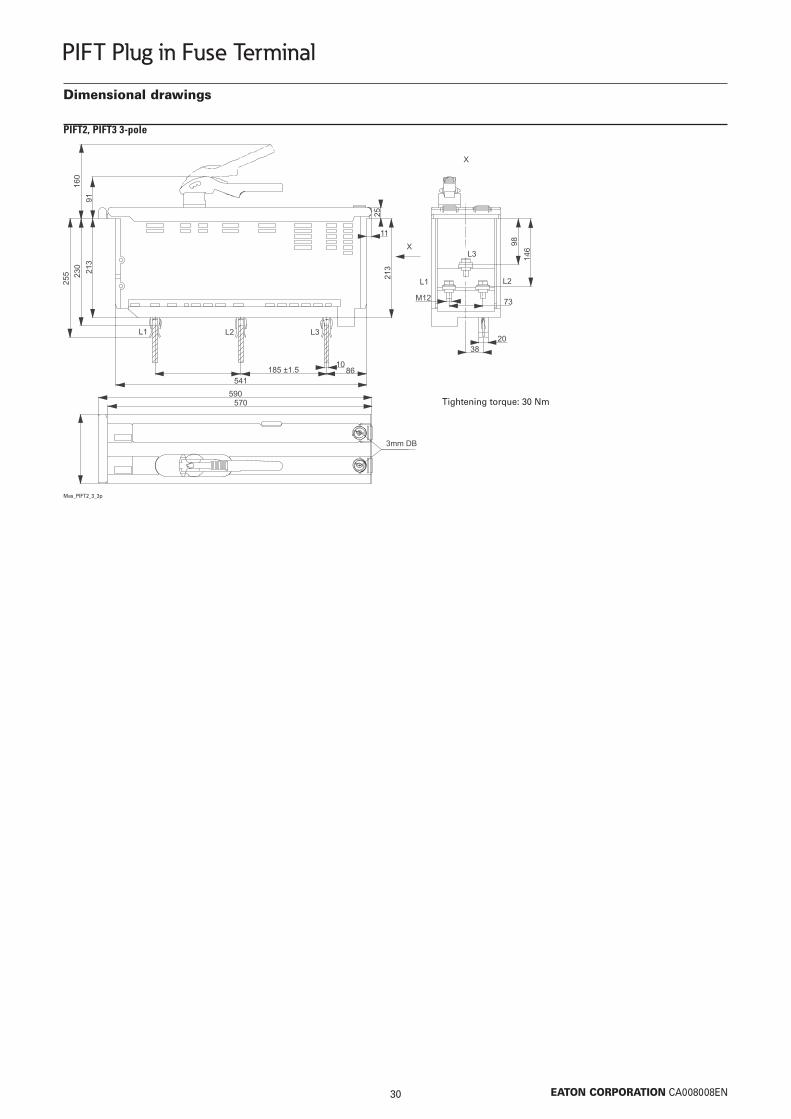
PIFT2, PIFT3 3-pole
Tightening torque: 30 Nm
Mas_PIFT2_3_3p
31 EATON CORPORATION CA008008EN
PIFT Plug in Fuse Terminal
Dimensional drawings
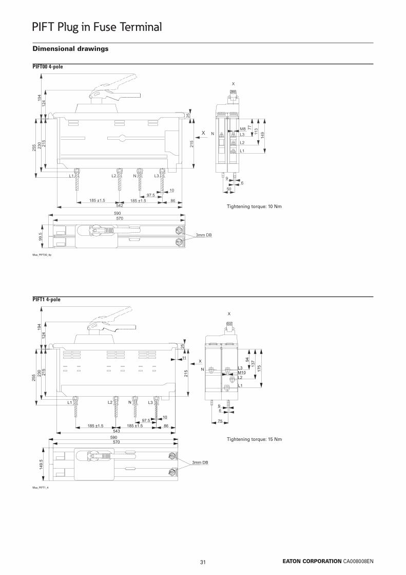
PIFT00 4-pole
Tightening torque: 10 Nm
Mas_PIFT00_4p
PIFT1 4-pole
Tightening torque: 15 Nm
Mas_PIFT1_4

32 EATON CORPORATION CA008008EN
PIFT Plug in Fuse Terminal
Dimensional drawings
PIFT2, PIFT3 4-pole
Tightening torque: 30 Nm
Mas_PIFT2_3_4p
33 EATON CORPORATION CA008008EN
PIFT Plug in Fuse Terminal
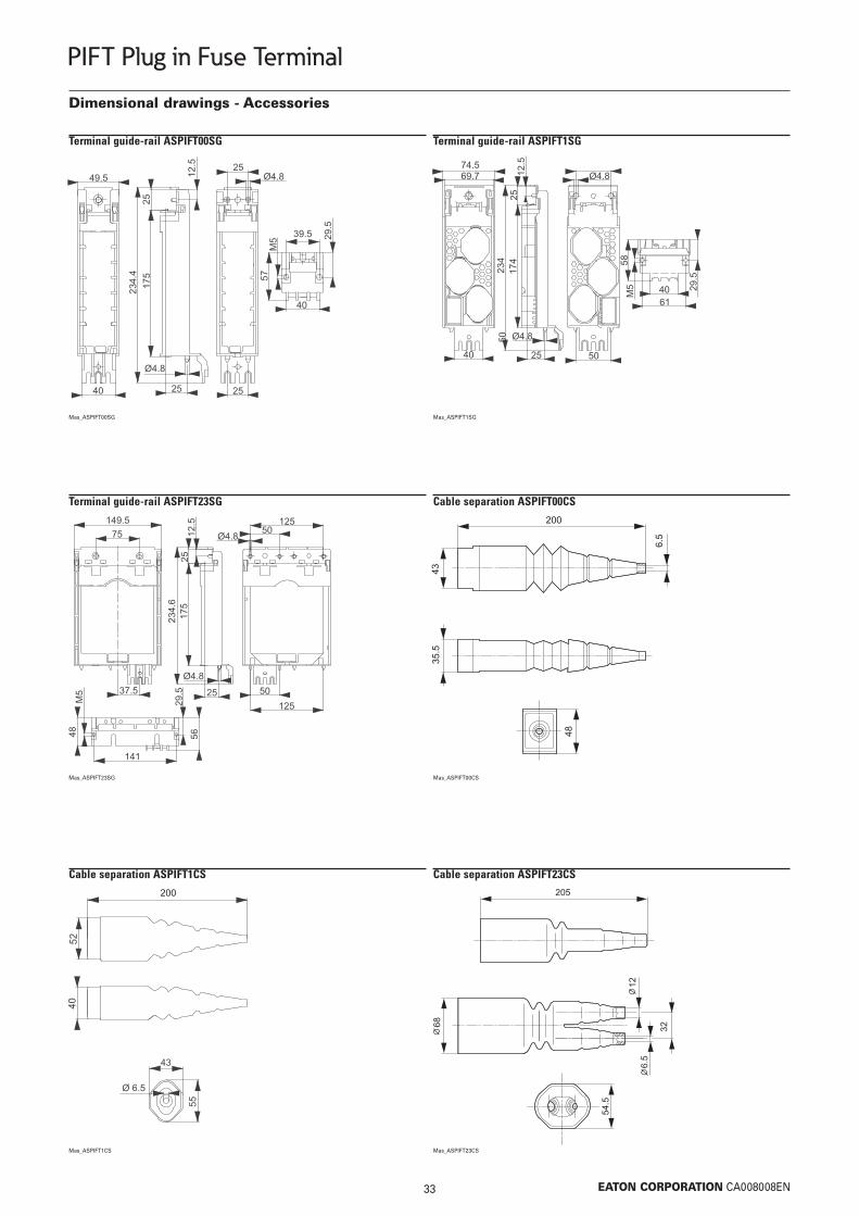
Dimensional drawings - Accessories
Terminal guide-rail ASPIFT00SG
Mas_ASPIFT00SG
Terminal guide-rail ASPIFT1SG
Mas_ASPIFT1SG
Terminal guide-rail ASPIFT23SG
Mas_ASPIFT23SG
Cable separation ASPIFT00CS
Mas_ASPIFT00CS
Cable separation ASPIFT1CS
Mas_ASPIFT1CS
Cable separation ASPIFT23CS
Mas_ASPIFT23CS

34 EATON CORPORATION CA008008EN
PIFT Plug in Fuse Terminal
Dimensional drawings - Accessories
Safety shield for terminal guide-rail ASPIFTURP
Mas_ASPIFTURP
Connector strip ASPIFTUSC
Mas_ASPIFTUSC
Switch-on lock ASPIFT00CL
Mas_ASPIFT00CL
Switch-on lock ASPIFT23CL
Mas_ASPIFT23CL
Pull-out tool ASPIFTUDT
Mas_ASPIFTUDT
Spare-space cover ASPIFT00PC, ASPIFT1PC, ASPIFT23PC
Mas_ASPIFT00PC
Type A
ASPIFT00PC 49.5ASPIFT1PC 74.5ASPIFT23PC 149.5

35 EATON CORPORATION CA008008EN
PIFT Plug in Fuse Terminal
Dimensional drawings - Accessories
Cover with switch-handle ASPIFT00SC
Mas_ASPIFT00SC
Cover with switch-handle ASPIFT1SC
Mas_ASPIFT1SC
Cover with switch-handle ASPIFT2SC, ASPIFT3SC
Mas_ASPIFT2SC
Auxiliary switch ASPIFTUAX
Mas_ASPIFTUAX
Analog measuring device ASPIFT00CT
Mas_ASPIFT00CT
Analog measuring device ASPIFTUCT
Mas_ASPIFTUCT

36 EATON CORPORATION CA008008EN
PIFT Plug in Fuse Terminal
Current transformer ASPIFTUCTC
Mas_ASPIFTUCTC
Dimensional drawings - Accessories

37 EATON CORPORATION CA008008EN
Fuse Devices
Fuse Devices
Fuse Devices - Series FCF
Fuse Devices - Series NH-SLS and NHW-SLS
SG09610
vt40815

38 EATON CORPORATION CA008008EN
Fuse Devices - Series FCF NHNH In-line Fuse Switch Disconnectors, 3 poles, FCFSDNH
Center-to-center distance of 100 mm between the phases - size 00160 160 160 00 FCFSDNH00BB100 149430 1SG09310
Max. Rated Max. Size Type Article No. PackOperational Fuse-link designation (pcs.)Current 500V 690VIe (A) (A) (A)
• Incl. cover for connection area• Mounting without the need of drilling (Accessories)• Connection either at the top or at the bottom
Center-to-center distance of 100 mm between the phases - size 00 - for installing current transformers• Equipped with spacer pins for retro-fitting of current transformers if ever the need should araise160 160 160 00 FCFSDNH00BB100-CTO 149431 1
Center-to-center distance of 185 mm between the phases - size 1 to size 3250 250 250 1 FCFSDNH1BB185 149436 1
400 400 400 2 FCFSDNH2BB185 149437 1
630 630 630 3 FCFSDNH3BB185 149438 1
SG09410
Center-to-center distance of 185 mm between the phases - size 1 to size 3 - for installing current transformers• Equipped with spacer pins for retro-fitting of current transformers if ever the need should araise
250 250 250 1 FCFSDNH1BB185-CTO 149439 1
400 400 400 2 FCFSDNH2BB185-CTO 149440 1
630 630 630 3 FCFSDNH3BB185-CTO 149441 1
39 EATON CORPORATION CA008008EN
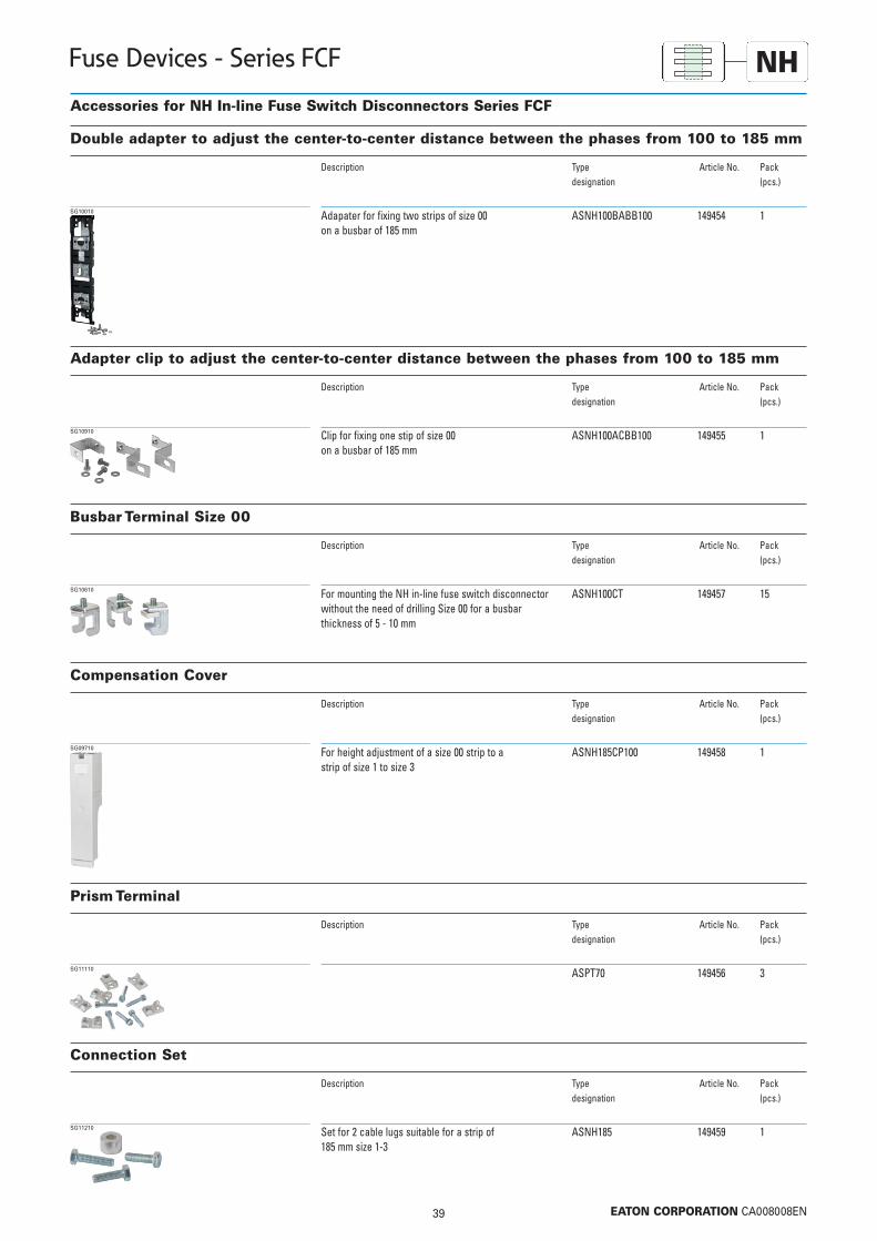
Fuse Devices - Series FCF NHAccessories for NH In-line Fuse Switch Disconnectors Series FCF
Adapater for fixing two strips of size 00 ASNH100BABB100 149454 1on a busbar of 185 mm
SG10010
Description Type Article No. Pack designation (pcs.)
Double adapter to adjust the center-to-center distance between the phases from 100 to 185 mm
Clip for fixing one stip of size 00 ASNH100ACBB100 149455 1on a busbar of 185 mm
SG10910
Description Type Article No. Pack designation (pcs.)
Adapter clip to adjust the center-to-center distance between the phases from 100 to 185 mm
For mounting the NH in-line fuse switch disconnector ASNH100CT 149457 15without the need of drilling Size 00 for a busbar thickness of 5 - 10 mm
SG10610
Description Type Article No. Pack designation (pcs.)
Busbar Terminal Size 00
For height adjustment of a size 00 strip to a ASNH185CP100 149458 1strip of size 1 to size 3
SG09710
Description Type Article No. Pack designation (pcs.)
Compensation Cover
ASPT70 149456 3SG11110
Description Type Article No. Pack designation (pcs.)
Prism Terminal
Set for 2 cable lugs suitable for a strip of ASNH185 149459 1185 mm size 1-3
SG11210
Description Type Article No. Pack designation (pcs.)
Connection Set

40 EATON CORPORATION CA008008EN
Fuse Devices - Series FCF NH
Cover for connection area, size 1-3 ASNH185CP123 170267 1SG63212
Description Type Article No. Pack designation (pcs.)
Cover for connection areas
Handle connection ASNH185HCK 149460 10SG11010
Description Type Article No. Pack designation (pcs.)
Connection Assembly Kit - consisting of 3 different items
• For parallel switching of 2 strips of size 2 or 3
Busbar kit ASNH185RK 149461 1SG10710
Cover for connection area ASNH185CP 149462 1SG09910
100/5 0.5 1 ASCNH100CT100-5-05 149432 3150/5 0.5 1.5 ASCNH100CT150-5-05 149433 3100/5 1 1.5 ASCNH100CT100-5-1 149434 3150/5 1 2.5 ASCNH100CT150-5-1 149435 3
SG00611
Transformation G Class Rated Apparent Power Type Article No. Pack(A) (VA) designation (pcs.)
Current transformer for 100 mm center-to-center distance between the phases
150/5 0.5 1.5 ASCNH185CT150-5-05 149442 3250/5 0.5 2.5 ASCNH185CT250-5-05 149443 3300/5 0.5 2.5 ASCNH185CT300-5-05 149444 3400/5 0.5 2.5 ASCNH185CT400-5-05 149445 3500/5 0.5 2.5 ASCNH185CT400-5-05 149446 3600/5 0.5 2.5 ASCNH185CT600-5-05 149447 3150/5 1 2.5 ASCNH185CT150-5-1 149448 3250/5 1 3.75 ASCNH185CT250-5-1 149449 3300/5 1 3.75 ASCNH185CT300-5-1 149450 3400/5 1 5 ASCNH185CT400-5-1 149451 3500/5 1 5 ASCNH185CT500-5-1 149452 3600/5 1 5 ASCNH185CT600-5-1 149453 3
SG00611
Transformation G Class Rated Apparent Power Type Article No. Pack(A) (VA) designation (pcs.)
Current transformer for 185 mm center-to-center distance between the phases

41 EATON CORPORATION CA008008EN
Fuse Devices - Series FCF NHNH In-line Fuse Switch Disconnectors, 3 poles, FCFSDNH00BB100...• Center-to-center distance of 100 mm between the phases • Size 00
Technical Data
FCFSDNH00BB100(-CTO)
ElectricalFor LV HRC fuse-links acc. to DIN VDE 0636-2 Size 000/00Rated operating voltage Ue V AC 690Rated operating current Ie
1) A 160Conv. free air thermal current Ith with fuse-links 1) A 160Conv. free air thermal current Ith with solid-links 1) A 210Rated frequency Hz 40 - 60Rated insulation voltage Ui V AC 800Total power loss at Ith (without fuse-links) Pv W 18Rated impuls withstand voltage Uimp kV 8Utilization category (AC-22B) 400 V A 160 500 V A 160 690 V A 100Conditional rated short-circuit current 2) kA 80Rated short-time withstand current Icw ka –Max. permissible power loss Pa per fuse-link W 12
MechanicalFlat terminal Bolt diameter M8 Cable lug (DIN 46235) mm2 1 x 10-95 (max. 25 mm width) Flat bar mm 20 x 10 Tightening torque Ma Nm 12 - 15Terminal Terminal capacity mm2 round 1,5 - 70 Cu / flat 6 x 9 x 0,8 Tightening torque Ma Nm 2,6Degree of protection, front side, device fitted Operating condition IP30 Switching element open IP10Ambient temperature Tamb
3) °C -25 up to +55Rated operating mode uninterrupted dutyActuation dependent manual operationMounting position vertical, horizontalAltitude m up to 2000Pollution degree 3Overvoltage category III
1) In case of mounting several units in low voltage switchgear-combinations , please consider rated diversity factors acc. to EN 60439-1.2) Type-tested with LV-HRC-fuse-links characteristic gG.3) 35°C Normal temperature, at 55°C with reduced operating current.

42 EATON CORPORATION CA008008EN
Fuse Devices - Series FCF NHDimensions (mm)
FCFSDNH00BB100 Outgoers at the top
Outgoers at the bottom
FCFSDNH00BB100-CTOOutgoers at the top
Outgoers at the bottom
Installation of a trans-former is possible at
the bottom
Installation of a 3-pole or 1-pole trans-former is possible
NH In-line Fuse Switch Disconnectors, 3 poles, center-to-center distance of 100 mm between the phases, size 00
43 EATON CORPORATION CA008008EN
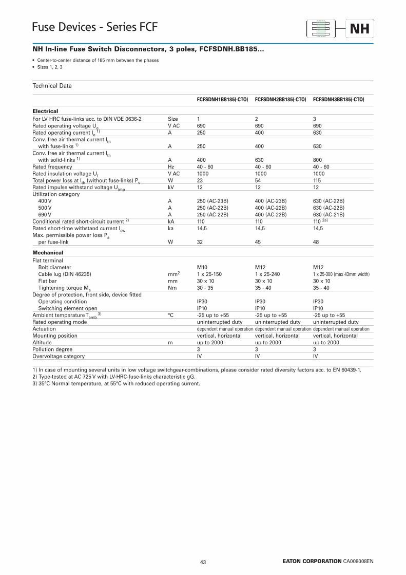
Fuse Devices - Series FCF NHNH In-line Fuse Switch Disconnectors, 3 poles, FCFSDNH.BB185...• Center-to-center distance of 185 mm between the phases• Sizes 1, 2, 3
Technical Data
FCFSDNH1BB185(-CTO) FCFSDNH2BB185(-CTO) FCFSDNH3BB185(-CTO)
ElectricalFor LV HRC fuse-links acc. to DIN VDE 0636-2 Size 1 2 3Rated operating voltage Ue V AC 690 690 690Rated operating current Ie
1) A 250 400 630Conv. free air thermal current Ith with fuse-links 1) A 250 400 630Conv. free air thermal current Ith with solid-links 1) A 400 630 800Rated frequency Hz 40 - 60 40 - 60 40 - 60Rated insulation voltage Ui V AC 1000 1000 1000Total power loss at Ith (without fuse-links) Pv W 23 54 115Rated impulse withstand voltage Uimp kV 12 12 12Utilization category 400 V A 250 (AC-23B) 400 (AC-23B) 630 (AC-22B) 500 V A 250 (AC-22B) 400 (AC-22B) 630 (AC-22B) 690 V A 250 (AC-22B) 400 (AC-22B) 630 (AC-21B)Conditional rated short-circuit current 2) kA 110 110 110 2a)
Rated short-time withstand current Icw ka 14,5 14,5 14,5Max. permissible power loss Pa per fuse-link W 32 45 48
MechanicalFlat terminal Bolt diameter M10 M12 M12 Cable lug (DIN 46235) mm2 1 x 25-150 1 x 25-240 1 x 25-300 (max 43mm width) Flat bar mm 30 x 10 30 x 10 30 x 10 Tightening torque Ma Nm 30 - 35 35 - 40 35 - 40Degree of protection, front side, device fitted Operating condition IP30 IP30 IP30 Switching element open IP10 IP10 IP10Ambient temperature Tamb
3) °C -25 up to +55 -25 up to +55 -25 up to +55Rated operating mode uninterrupted duty uninterrupted duty uninterrupted dutyActuation dependent manual operation dependent manual operation dependent manual operationMounting position vertical, horizontal vertical, horizontal vertical, horizontalAltitude m up to 2000 up to 2000 up to 2000Pollution degree 3 3 3Overvoltage category IV IV IV
1) In case of mounting several units in low voltage switchgear-combinations, please consider rated diversity factors acc. to EN 60439-1.2) Type-tested at AC 725 V with LV-HRC-fuse-links characteristic gG.3) 35°C Normal temperature, at 55°C with reduced operating current.

44 EATON CORPORATION CA008008EN
Fuse Devices - Series FCF NHDimensions (mm)
FCFSDNH1BB185
Connection at the top (Ao)Connection at the bottom (Au)
FCFSDNH2BB185, FCFSDNH3BB185
Connection at the top (Ao)Connection at the bottom (Au)
NH In-line Fuse Switch Disconnectors, 3 poles, center-to-center distance of 185 mm between the phases, size 1 - size 3

45 EATON CORPORATION CA008008EN
Fuse Devices - Series FCF NHDimensions (mm)
FCFSDNH1BB185-CTO
Connection at the top (Ao)Connection at the bottom (Au)
FCFSDNH2BB185-CTO, FCFSDNH3BB185-CTO
Connection at the top (Ao)Connection at the bottom (Au)
NH In-line Fuse Switch Disconnectors, 3 poles, center-to-center distance of 185 mm between the phases , size 1 - size 3,for installing transformers
Installation of a 3-pole or 1-poletransformer is pos-sible
Installation of a 3-pole or 1-poletransformer is pos-sible

46 EATON CORPORATION CA008008EN
Fuse Devices - Series FCF NHDimensions (mm) - Accessories
ASNH100BABB100
Double Adapter
ASNH100ACBB100
Adapter Clips
ASNH100CT
Busbar Terminal Size 00
For mounting without the need ofdrilling, for a busbar thickness of5-10 mm
Tightening torque= 6 Nm
ASNH185CP100
Compensation Cover
ASNH185HCK
Handle Connection
ASNH185RK
Busbar Kit
ASNH185CP
Cover for Connection Area

47 EATON CORPORATION CA008008EN
Fuse Devices - Series FCF NHDimensions (mm) - Accessories
ASNH185CP123
Cover for Connection Area
48 EATON CORPORATION CA008008EN
Fuse Devices - Series NH-SLS and NHW-SLS
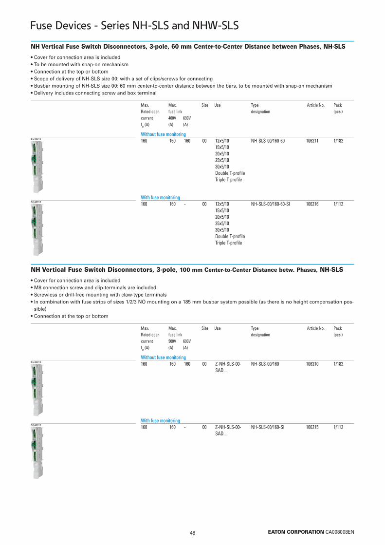
NH Vertical Fuse Switch Disconnectors, 3-pole, 60 mm Center-to-Center Distance between Phases, NH-SLS
Without fuse monitoring 160 160 160 00 12x5/10 NH-SLS-00/160-60 106211 1/182
15x5/1020x5/10 25x5/1030x5/10Double T-profileTriple T-profile
SG46912
Max. Max. Size Use Type Article No. PackRated oper. fuse link designation (pcs.)current 400V 690VIe (A) (A) (A)
• Cover for connection area is included• To be mounted with snap-on mechanism • Connection at the top or bottom• Scope of delivery of NH-SLS size 00: with a set of clips/screws for connecting• Busbar mounting of NH-SLS size 00: 60 mm center-to-center distance between the bars, to be mounted with snap-on mechanism• Delivery includes connecting screw and box terminal
With fuse monitoring160 160 - 00 12x5/10 NH-SLS-00/160-60-SI 106216 1/112
15x5/1020x5/10 25x5/1030x5/10Double T-profileTriple T-profile
SG46912
NH Vertical Fuse Switch Disconnectors, 3-pole, 100 mm Center-to-Center Distance betw. Phases, NH-SLS
Without fuse monitoring160 160 160 00 Z-NH-SLS-00- NH-SLS-00/160 106210 1/182
SAD...
SG46912
Max. Max. Size Use Type Article No. PackRated oper. fuse link designation (pcs.)current 500V 690VIe (A) (A) (A)
• Cover for connection area is included• M8 connection screw and clip-terminals are included• Screwless or drill-free mounting with claw-type terminals• In combination with fuse strips of sizes 1/2/3 NO mounting on a 185 mm busbar system possible (as there is no height compensation pos-
sible) • Connection at the top or bottom
With fuse monitoring160 160 - 00 Z-NH-SLS-00- NH-SLS-00/160-SI 106215 1/112
SAD...
SG46912

49 EATON CORPORATION CA008008EN
Fuse Devices - Series NH-SLS and NHW-SLS
NH Vertical Fuse Switch Disconnectors, 3-pole, 185 mm Center-to-Center Distance betw. Phases, NHW-SLS
Without fuse monitoring160 160 160 00 high NHW-SLS-00/H 179754 1
version160 160 160 00 flat NHW-SLS-00/F 179755 1
version250 250 250 1 NHW-SLS-1 179756 1
400 400 400 2 NHW-SLS-2 179757 1
630 630 630 3 NHW-SLS-3 179758 1
VT40815
Max. Max. Size Notes Type Article No. PackRated oper. fuse link designation (pcs.)current 500V 690VIe (A) (A) (A)
• With integrated cover for the connection area (additional cover for cable area is possible)• Drill-free mounting using claw-type terminals for size 00 (Z-NHW-SLS-00-BBC, Article No. 179770)• Drill-free mounting using claw-type terminals for sizes 1,2,3 (Z-NHW-SLS-00-BBC, Article No. 179771)• Self-closing test holes integrated in the cover • High version for size 00 = suitable for mounting a current transformer• Flat version for size 00 = NO direct mounting of a current transformer possible, height compensation to construction depth for sizes 1,2,3
via an adapter (NHW-SLS-00-185/185-SADD, Article No. 179764), mounting a current transformer is possible if an adapter is used • Connection at the top or bottom
With fuse monitoring160 160 160 00 high NHW-SLS-00/H/SI 179759 1
version160 160 160 00 flat NHW-SLS-00/F/SI 179760 1
version250 250 250 1 NHW-SLS-1/SI 179761 1
400 400 400 2 NHW-SLS-2/SI 179762 1
630 630 630 3 NHW-SLS-3/SI 179763 1
VT40515

50 EATON CORPORATION CA008008EN
Fuse Devices - Series NH-SLS and NHW-SLS
Accessories for NH Vertical Fuse Switch Disconnectors of the NH-SLS and NHW-SLS Series
Double adapter 185/185 - flat version Z-NHW-SLS-00-185/185-SADD 179764 1VT41515
Description Type Article No. Pack designation (pcs.)
Bar adapter - depth compensation (185/185)• Adapter + NHW-SLS-00/F = same construction depth as NHW-SLS-1,2,3
NHW-SLS-00/F+H Z-NHW-SLS-00-BBC 179770 3VT42415
Can be used for Type Article No. Pack designation (pcs.)
Claw-type terminals for size 00 (185mm)• Screwless fixing of size 00 fuse strips, 185 mm center-to-center distance between phases
NHW-SLS-1+2+3 Z-NHW-SLS-1+2+3-BBC 179771 3VT42315
Can be used for Type Article No. Pack designation (pcs.)
Claw-type terminals for sizes 1,2,3 (185mm)• Screwless fixing of size 1/2/3 fuse strips
Size 00NH-SLS-00/160 Z-NH-SLS-KA 106223 2wa_sg01712
Can be used for Type Article No. Pack designation (pcs.)
Cover for connection area, 60/100 mm center-to-center distance between phases
51 EATON CORPORATION CA008008EN
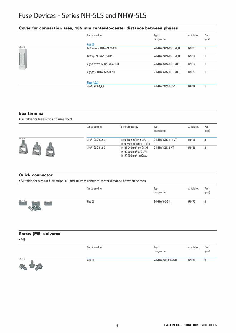
Fuse Devices - Series NH-SLS and NHW-SLS
Size 00flat/bottom, NHW-SLS-00/F Z-NHW-SLS-00-TC/F/D 179767 1
flat/top, NHW-SLS-00/F Z-NHW-SLS-00-TC/F/U 179768 1
high/bottom, NHW-SLS-00/H Z-NHW-SLS-00-TC/H/D 179752 1
high/top, NHW-SLS-00/H Z-NHW-SLS-00-TC/H/U 179753 1
VT42015
Can be used for Type Article No. Pack designation (pcs.)
Cover for connection area, 185 mm center-to-center distance between phases
Sizes 1/2/3NHW-SLS-1,2,3 Z-NHW-SLS-1+2+3 179769 1
NHW-SLS-1, 2, 3 1x50-185mm2 rm Cu/Al Z-NHW-SLS-1+2-VT 179765 31x70-240mm2 sm/se Cu/Al
NHW-SLS-1 ,2 ,3 1x185-240mm2 sm Cu/Al Z-NHW-SLS-3-VT 179766 31x150-300mm2 se Cu/Al1x120-300mm2 rm Cu/Al
VT42615
Can be used for Terminal capacity Type Article No. Pack designation (pcs.)
Box terminal• Suitable for fuse strips of sizes 1/2/3
Size 00 Z-NHW-00-BK 179773 3VT42815
Can be used for Type Article No. Pack designation (pcs.)
Quick connector• Suitable for size 00 fuse strips, 60 and 100mm center-to-center distance between phases
Size 00 Z-NHW-SCREW-M8 179772 3VT42715
Can be used for Type Article No. Pack designation (pcs.)
Screw (M8) universal• M8

52 EATON CORPORATION CA008008EN
Fuse Devices - Series NH-SLS and NHW-SLS
Suitable for size 0080/5 1 5 Z-NHW-CT-80/5-1 179775 1
150/5 1 5 Z-NHW-CT-150/5-1 179776 1
VT42215
Transformation G Class Rated Apparent Power Type Article No. Pack(VA) designation (pcs.)
Current transformer suitable for NHW-SLS-00, 1, 2, 3• For size 00 use the high version of the strips (NHW-SLS-00/H)• No additional space required, can be installed in the standard strip • Claw-type mounting is still possible • Transformer conductors to be fixed with Z-NH-SLS-1+2+3-BC fixing clips
Suitable for sizes 1,2,3 and for adapter Z-NHW-SLS-00-185/185-SADD150/5 1 1.5 Z-NHW-CT-150/5-1-2 182398 1
200/5 1 1.5 Z-NHW-CT-200/5-1 179748 1
250/5 1 2.5 Z-NHW-CT-250/5-1 179749 1
400/5 1 2.5 Z-NHW-CT-400/5-1 179750 1
600/5 1 2.5 Z-NHW-CT-600/5-1 179751 1
VT42115
Z-NH-SLS-00-BC 106229 3wa_sg06606
Type Article No. Pack designation (pcs.)
Fixing clip• For current transformer on busbar adapter in the 185mm busbar system (size 00)
Z-NHW-SPK 182491 1vt57115
Type Article No. Pack designation (pcs.)
Connection strap with brace terminal• Universal use• Direct mounting on Cu rails• Not suitable for fuse strips of the NHW-SLS series• Drill hole for connection screw Ø 13 in the connection strap• For cross sections of 120-300mm2

53 EATON CORPORATION CA008008EN
Fuse Devices - Series NH-SLS and NHW-SLS
NH Vertical Fuse Switch Disconnectors, 3-pole, 60 and 100mm Center-to-Center Distance betw. Phases, NH-SLS
Technical Data
Version in accordance with IEC 60947-1: 2007 + A1: 2010, IEC 60947-3: 2008 + A1: 2012
3-pole switching
Connection at the top and bottom
Arc quenching deviceFor NH fuse links according to IEC 60269-2-1 size NH00Contact protection even with open switch covers and in parking position Mechanical interlock of fuse links Degree of protection (front side), Degree of protection in the connection area depends on the installation position IP30Connection contacts - Screw M8, clip 2xM5, clear diameter 12mm - Prismatic terminal connection Cu, Al * 16-70mm2 rm, sm, f+AE
* Connections to aluminium conductors are not maintenance-freeFor 60mm center-to-center distance between bars screwless busbar contactingFor 100 mm center-to-center distance between bars - for screw-fixing on busbars with drill holes, screw M8 - drill-free mounting with clamping bracket Version 3-pole switchingType of current AC (50-60 Hz)Rated operating voltage Ue ** V AC 690Rated insulation voltage Ui ** V 1000Rated impulse withstand voltage Uimpwithout fuse monitoring ** kV 8Rated operating current Ie * A 160Utilization categories without fuse monitoring ** AC22B (690 V) AC23B (400 V) AC23B (500 V 125 A)Conditional rated short-circuit current *** kA 50For NH fuse links acc. to IEC 60269-2 with power loss per phase up to W 12
Indicator switch for displaying the cover position:2 switches (change-over) can be used Rated operating voltage V AC 250 V DC 30Rated operating current A AC 5 A DC 4
Electronic fuse monitoring:2 LED indicatorsMemory functions and remote reset can be programmed2 changers2x Cu 2.5 mm2 massive, DIN 46288 or 2x Cu1.5 mm2 litz wire with ferrule, DIN 46228-1 /-2 /-3Internal resistance of measurement paths within MOhm range, VDE regulations regarding contact voltage (> 1000 Ohm/V) are compliedwithFor disconnecting switch off the upstream main switch
* For permanent simultaneous operation of several devices please respect the rated load factor acc. to IEC/EN 61439-2, table 101.With AC23B please make sure a distance of 50 mm at the top and 25 mm at the side is guaranteed with regard to grounded components.
** Fuse monitoring Ue, Ui 400 V AC, Uimp 4 kV, VG2 (mains connections)*** Type-tested with fuse links of operating class gL/gG

54 EATON CORPORATION CA008008EN
Fuse Devices - Series NH-SLS and NHW-SLS
NH Vertical Fuse Switch Disconnectors, 3-pole, 185mm Center-to-Center Distance betw. Phases, NH-SLS
Technical Data
Version in accordance with IEC 60947-1: 2007 + A1: 2010, IEC 60947-3: 2008 + A1: 201
1 and 3-pole switchingFor NH fuse links according to IEC 60269-2-1 size NH00, 1, 2, 3Can be mounted on a 185mm system by screw-fixing on busbars with drill holes Screw M8 for size 00, Screw M12 for sizes 1, 2, 3Optionally drill-free with a clamping bracket for busbars (10 mm thick) and profile rails Cable connections at the top and bottom by turning the bottom part of the strip Contact protection and switch-on aids Contact protection even with open switch covers and in parking position Mechanical interlocking of fuse links in switch covers Degree of protection (front side), Degree of protection in the connection area depends on the installation position IP20Test holes in the switch covers are self-closing Cover of connection area (Accessories) for lateral contact protection
Conductor connections:Size Screw-type Direct connection Box terminal Clip or prismatic Clip/Prismatic connection terminals connection connection Cu and Al* terminal area for flat Cu conductor00 M8 - 1x1.5-70mm2 1x10-70mm2 12x(1-10)mm 70mm2** rm, sm, f, f+AE 1x95mm2
rm, sm, f1, 2 M12 1x35-150mm2 sm Cu/Al - - 2x185mm2- 1x50-185mm2 se 1x50-185mm2 rm 240mm2 1x35-70mm2 rm 1x70-240mm2 sm/se 1x50mm2 re Md 32-40Nm 2x35-150mm2 sm 2x50-185mm2 se 2x35-70mm2 rm 2x35-50mm2 re Md 18-24 Nm3 M12 1x35-150mm2 sm Cu/Al - - 2x185mm2- 1x50-185mm2 se 1x185-240mm2 sm 240mm2 1x35-70mm2 rm 1x150-300mm2 se 1x50mm2 re 1x120-300mm2 rm Md 32-40Nm 2x35-150mm2 sm 2x50-185mm2 se 2x35-70mm2 rm 2x35-50mm2 re Md 18-24 Nm * Connections to aluminium conductors are not maintenance-free ** Copper conductors for relevant rated currents according to IEC/EN 60947-1
Size 00 1 2 3Type of current AC (50 Hz) AC (50 Hz) AC (50 Hz) AC (50 Hz)Rated operating voltage Ue ** 690 V AC 690 V AC 690 V AC 690 V ACRated insulation voltage Ui ** 1000 V 1000 V 1000 V 1000 VRated peak withstand voltage Uimpwithout fuse monitoring ** 8 kV 8 kV 8 kV 8 kVUtilization categories without fuse monitoring ** AC22B AC23B AC23B AC23B (160A/500V) (250A/400V) (400A/400V) (630A/400V) AC23B AC22B AC22B AC22B (160A/400V) (250A/690V) (400A/690V) (630A/400V) AC21B AC21B AC21B (250A/690V) (400A/690V) (630A/400V)Conditional rated short-circuit current, 3-pole switching *** 100kA/500V 80kA/500V 80kA/500V 80kA/500V 100kA/690V 80kA/690V 80kA/690V 80kA/690VConditional rated short-circuit current, 1-pole switching *** 100kA/500V 80kA/500V 80kA/500V 80kA/500V 100kA/690V 80kA/690V 80kA/690V 80kA/690VFor NH fuse links acc. to IEC 60269-2 **** with power loss per phase up to 12W 23W 34W 48W

55 EATON CORPORATION CA008008EN
Fuse Devices - Series NH-SLS and NHW-SLS
NH Vertical Fuse Switch Disconnectors, 3-pole, 185mm Center-to Center Distance betw. Phases, NH-SLS
Technical Data (continued)
Size 3 as double NH vertical fuse disconnector 1250A:3-pole, 690 V AC, 2x630A, 3-pole switching, conditional rated short-circuit current up to 80kAWith fuses gL/gG, utilization categories AC20B (690V)
Indicator switch for displaying the cover position:3 switches (change-over) can be used for sizes 00, 1, 2, 3Rated operating voltage V AC 250 V DC 30Rated operating current A AC 5 A DC 4
Electronic fuse monitoring:2 LED indicators Memory functions and remote reset can be programmed 2 x change-over2x Cu 2.5 mm2 massive, DIN 46288 or 2x Cu1.5 mm2 litz wire with ferrule, DIN 46228-1 /-2 /-3Internal resistance of measurement paths within MOhm range, VDE regulations regarding contact voltage (> 1000 Ohm/V) are compliedwithFor disconnecting switch off the upstream main switch
* For permanent simultaneous operation of several devices please respect the rated load factor acc. to IEC/EN 61439-2, table 101.Please make sure a distance of 50 mm at the top and 25 mm at the side is guaranteed with regard to grounded components.
** Fuse monitoring Ue, Ui 400 V AC, Uimp 4 kV, VG2 (mains connections)*** Type-tested with fuse links of operating class gL/gG**** NH fuse links of size 1 can be used in NHW-SLS of size 2

56 EATON CORPORATION CA008008EN
Fuse Devices - Series NH-SLS and NHW-SLS
Dimensions (mm)
670
5 0
5.5
2.5
285
185
185
1 50
7278
650
3 6 36
37
38
1 89
406max.
High version - Same height as sizes 1, 2, 3 - Installation of a transformer is possible!NH Vertical Fuse Switch Disconnector NHW-SLS-00/H
50
830
278
167
650
445
185
185
1 50
189
Incl. fuse monitoring - high version - Same height as sizes 1, 2, 3 - Installation of a transformer is possible!NH Vertical Fuse Switch Disconnector NHW-SLS-00/H/SI

57 EATON CORPORATION CA008008EN
Fuse Devices - Series NH-SLS and NHW-SLS
Dimensions (mm)
5.52.5
50
670
7
38
37
3 6 36
285
185
185
278
1 47
108
650
16
364max.
Flat version - In order to reach the same depth as with sizes 1, 2, 3 you need to use an additional adapter (NHW-SLS-00-185/185-SADD_179764) -Installation of a transformer is only possible if you use a device adapter
NH Vertical Fuse Switch Disconnector NHW-SLS-00/F
50
830
147
108
278
650
185
185
445
Incl. fuse monitoring - flat version - In order to reach the same depth as with sizes 1, 2, 3 you need to use an additional adapter (NHW-SLS-00-185/185-SADD_179764) - Installation of a transformer is only possible if you use a device adapter
NH Vertical Fuse Switch Disconnector NHW-SLS-00/F/SI

58 EATON CORPORATION CA008008EN
Fuse Devices - Series NH-SLS and NHW-SLS
Dimensions (mm)
++
+
+
+
+
max.
3.3B
3.4
M6, 5 - 6 Nm
44 - 53 Ib.in
SW 4
M5, 3 - 4 Nm
27 - 35 Ib.in
SW 4
2
clic
1
++
+
+
+
+
max.
++
+
+
+
+
max.
1,5 - 70 mm²
20
mm
<12
mm
10 - 50 mm²
rm, sm,f, f+AE
70 - 95 mm²
70 mm² rm, sm,f, f+AE
95 mm² rm, sm, f
3.3C
3.3A
M8, 8 - 10 Nm
70 - 90 Ib.in
SW 13
max. Kabelschuh Cable lugs
DIN 46 234 70 mm²
DIN 46 235 70 mm²
Cable connection for size 00 flat and high version:

59 EATON CORPORATION CA008008EN
Fuse Devices - Series NH-SLS and NHW-SLS
Dimensions (mm)
50
670
99
49.5
2
285
185
185
1 50
190
278
650
7
6 2.5
470max.
NH Vertical Fuse Switch Disconnector NHW-SLS-1/2/3
Cable connection NHW-SLS-1/2/3

60 EATON CORPORATION CA008008EN
Fuse Devices - Series NH-SLS and NHW-SLS
Dimensions (mm)
50
99
185
185
445
167
278
650
1 50
189
63.5
49.5
With fuse monitoringNH Vertical Fuse Switch Disconnector NHW-SLS-1/2/3-SI
With fuse monitoringCable connection NHW-SLS-1/2/3-SI

61 EATON CORPORATION CA008008EN
Fuse Devices - Series NH-SLS and NHW-SLS
Dimensions (mm) - Accessories
185
185
5 0
83
20
445
1 4.5
42
Z-NHW-SLS-00-185/185-SADD
Double adapter
29
43.2
2 5
12
22
9
Claw-type terminals for size 00
51.5
36.3
56
30
9.5
14.5
25.5
58.5
37
Claw-type terminals for sizes 1, 2, 3
W x H x D: 83 x 450 x 50Weight: 55 kg/100

62 EATON CORPORATION CA008008EN
Accessories for Panel Building - Connection Terminals
• Add-on terminals 1-, 3-, 4-, 5-pole
• Round conductors - sector conductors - flat conductors
• 25 – 1000 A
• Conversion sets
• Connections for auxiliary conductors
• Terminal covers
4300PIC-326
K-Type Connection Terminals
4300PIC-308
4300PIC-314
4300PIC-331

63 EATON CORPORATION CA008008EN
Accessories for Panel Building - Connection Terminals
K-Type Terminals
Rated Operating Current Ie 160 A1 1x16-95 1x35-70 (1x) 3x9x0.8 18x4 K95/1N 010773 13 up to K95/3 025017 14 (1x) 6x9x0.8 K95/4 027390 15 K95/5 029763 11 – – K95/1N/BR 012336 1
Poles Terminal Capacities1) Terminal Capacities1) Type Article No. Pack Cu Al Cu Band Cu Bar designation (pcs.) Aln mm2 mm2 mm mm
• External connection for round or sector conductors, other end for Cu band.• Suitable for copper and aluminium conductors • Adapter for band connection to cable connection
U, V, W – X, Y, Z – L1, L2, L3 – T1, T2, T3 – PE, N, PEN.• Ui = 1000 V AC• Incl. terminal labels
Rated Operating Current Ie 250 A1 1x35-150 1x35-120 (1x) 4x16x0.8 18x4 K150/1N 089085 13 or or up to K150/3 032136 14 2x16-70 2x35-50 (2x) 6x16x0.8 K150/4 034509 15 K150/5 036882 11 – – K150/1/BR 014709 1
Rated Operating Current Ie 400 A1 1x35-240 1x95-185 (1x) 6x16x0.8 25x15 K240/1N 091458 13 or or up to K240/3 039255 14 2x35-120 2x50-95 (1x) 10x16x0.8 K240/4 041628 15 K240/5 044001 11 – – K240/1/BR 017082 1
Rated Operating Current Ie 630 A1 1x150-300 1x150-240 (1x) 10x16x0.8 40x15 K2X240/1N 093831 13 or or up to K2X240/3 046374 14 2x50-240 2x95-185 (2x) 11x21x1 K2X240/4 048747 15 K2X240/5 051120 11 – – K2X240/1/BR 019455 1
Rated Operating Current Ie 800 A1 2x120-240 2x150-185 (2x) 11x21x1 50x20 K3X185/1 062985 13 or or K3X185/3 065358 14 3x50-185 3x95-150 K3X185/4 067731 15 K3X185/5 070104 1
Rated Operating Current Ie 1000 A1 2x150-300 2x150-240 (2x) 11x21x1 60x15 K3X240/1 060612 13 or or or K3X240/3 058239 14 3x50-240 3x150-185 10x40x1 K3X240/4 055866 15 or K3X240/5 053493 1
10x50x11 2x150-300 2x150-240 (2x) 11x21x1 60x15 K4X185/1 079596 13 or or or K4X185/3 077223 14 4x50-185 4x120-150 10x40x1 K4X185/4 074850 15 or K4X185/5 072477 1
10x50x1
1) Key Round cable, single-wired Round cable, multi-wired Sector cable, single-wired Sector cable, multi-wired Cu band Cu bar
Type K95/1N/BR, K150/1/BR,K240/1/BR and K2X240/1/BR = forround cable or sector cable connection on both sides
4300PIC-323 4300PIC-327
4300PIC-317 4300PIC-321
4300PIC-306 4300PIC-310
4300PIC-301 4300PIC-304
4300PIC-296 4300PIC-299
4300PIC-291 4300PIC-294

64 EATON CORPORATION CA008008EN
Accessories for Panel Building - Connection Terminals
Accessories, Terminal Cover
3, 4 and 5-poles respectivelyK95/... H-K95/5 036888 4K150/... H-K150/5 039261 1K240/... H-K240/5 041634 1K2X240/... H-K2X240/5 044007 1K3X185/... H-K3X185/5 048753 1K3X240/... H-K3X240/5 046380 1K4X185/... H-K4X185/5 051126 1
wa_vt23613
Suitable for Type Article No. Pack designation (pcs.)
• Incl. warning sign • According to DIN (electricity lightning bolt)• 3 or 4-pole terminal covers can be obtained by splitting
5-pole Terminal Cover
K95/... 160 D-K95 020277 1K150/... 250 D-K150 022650 1K240/... 400 D-K240 025023 1K2X240/... 630 D-K2X240 027396 1K3X185/... 800 D-K3X185 032142 1K3X240/... 1000 D-K3X240 029769 1K4X185/... 1000 D-K4X185 034515 1
VT10408
Suitable for Rated Permanent Type Article No. PackCurrent Iu (A) designation (pcs.)
• For one conductor• For conversion from band-type connection to cable-type connection
Conversion Sets for K-Type Terminals
K95/... + K150/... HK-K95-K150 001916 1K240/... HK-K240 098585 1K2X240/... HK-K2X240 010785 1K3X185/... HK-K3X185 015531 1K3X240/... HK-K3X240 013158 1K3X240/... + K4X185/.... HK-K3X240-K4X185 001917 1
VT12508
Suitable for Type Article No. Pack designation (pcs.)
• For one auxiliary conductor • M4-screw with pressure shim• Terminal capacity 0,5-2,5 mm2
3, 4 and 5-poles respectivelyK95/... K95-IPK 182400 2K150/... K150-IPK 182401 2K240/... K240-IPK 182402 2K2X240/... K2X240-IPK 182403 2
vt57915
Suitable for Type Article No. Pack designation (pcs.)
• for 3, 4, 5-pole K-Terminals• Degree of protection IP2X• only in connection with terminal cover H-K...
3, 4, 5-pole Finger Protection IP2X

65 EATON CORPORATION CA008008EN
Accessories for Panel Building - Connection Terminals
Accessories, Terminal Cover
150 2.5 - 50 3 x 9 x 0.8 K50/1 098573 102.5 - 502.5 - 35
4300PIC-283
Circuit Rated Permanent Terminal Capacities 1) Type Article No. PackCurrent Iu Cu Band designation (pcs.)A mm2 mm
• Finger-proof on all sides, VDE approved• For snap-fitting on top-hat rail to IEC/EN 60715• Can be screwed onto mounting plates and directly on CI enclosure stacking mandrels• Can be grouped with additional K50/1 terminals• With L, N, and protective conductor markings
Insulated Individual Terminals
1) Rundleiter eindrähtig Rundleiter feindrähtig mit fachgerecht verpresster Aderendhülse Rundleiter mehrdrähtig Sektorleiter eindrähtig Sektorleiter mehrdrähtig Cu-Band Cu-Schiene

66 EATON CORPORATION CA008008EN
Accessories for Panel Building - Connection Terminals
K-Type Terminals
Insulated Individual K50/1 Terminal
Type a a1 a2 a3 b b1 c a5 IK95/1N 37 - 18,5 3 115 100 88 - 13K95/3 99 75 12 3 115 100 88 31 13K95/4 130 100 15 3 115 100 88 31 13K95/5 161 125 18 3 115 100 88 31 13K150/1N 37 - 18,5 3 115 100 105 - 13K150/3 99 75 12 3 115 100 105 31 13K150/4 130 100 15 3 115 100 105 31 13K150/5 161 125 18 3 115 100 105 31 13K240/1N 52 - 26 3 115 100 120 - 12K240/3 144 100 22 3 115 100 120 46 12K240/4 190 150 20 3 115 100 120 46 12K240/5 236 175 30,5 3 115 100 120 46 12K2X240/1N 68 - 34 4 140 125 127 - 15K2X240/3 192 125 33,5 4 140 125 127 62 15K2X240/4 254 200 27 4 140 125 127 62 15K2X240/5 316 250 33 4 140 125 127 62 15K3X185/1 78 - 39 4 140 125 166 - 15K3X185/3 222 150 36 4 140 125 166 72 15K3X185/4 294 225 34,5 4 140 125 166 72 15K3X185/5 366 300 33 4 140 125 166 72 15K3X240/1 88 - 44 4 165 150 196 - 20K3X240/3 252 175 39 4 165 150 196 82 20K3X240/4 334 250 42 4 165 150 196 82 20K3X240/5 416 325 45,5 4 165 150 196 82 20K4X185/1 88 - 44 4 165 150 196 - 20K4X185/3 252 175 39 4 165 150 196 82 20K4X185/4 334 250 42 4 165 150 196 82 20K4X185/5 416 325 45,5 4 165 150 196 82 20
Standards: VDE approval in acc. The product complies with with DIN EN 60947-7-1 the EC's RoHS DirectivesColor: RAL 7035 light greyMaterials: Terminal body: Brass (CuZn39Pb2) blank Housing: PA 6 (halogen-free) Screws: Steel Zn, thick-film passivatedFlame-retardant: self-extinguishing
Mechanical values:Stripping lengths: 50 mm2 16 mmScrew heads: Hexagon socket-head screw: 5 mmDimensions: w × h × d (mm): 24.8 x 40.5 x 60.8
Electrical values:Rated uninterrupted current: 150 ARated operational voltage: 690 VTerminal capacities: 2x 50 mm2 Cu round conductor, solid Cu round conductor, stranded 2.5 – 50 mm2 Cu round conductor, flexible with ferrule 2.5 – 35 mm2 Cu ribbon cable 3 x 9 x 0.8 mmFor use with: CI, CI-K, cam switches T, switch-disconnectors P, circuit-breakers NZM; CU-BAND3X9x0.8-BK
4300PIC-283 4300PIC-284 4300PIC-285 4300PIC-286

67 EATON CORPORATION CA008008EN
Accessories for Panel Building - Filters and Fans
• Degree of protection IP54 and IP55
• Rated voltage 230V
• Fixing without any screws
• Fast changing of filter pads
• Thermoplastic material
• RAL 7035
• High class floating or ball bearing
• Self-extinguishing UL94 V0
• Simple change of air boost direction
• 4 corner arrester
• Variable connection per twisting of 90°
• Temperature range -40°C ... +55°C
wa_vt01814
wa_vt02314
Filter-based Fans, Filter Pads and Air Exit Filters

68 EATON CORPORATION CA008008EN
Accessories for Panel Building - Filters and Fans
Filter-based fan IP54
109x109 92x92 25/29 E-FAN1 167287 1145x145 125x125 61/70 E-FAN2 167288 1202x202 177x177 110/125 E-FAN3 167289 1252x252 223x223 156/171 E-FAN4 167290 1252x252 223x223 256/292 E-FAN5 167291 1
wa_vt01814
Dimensions Cut-out HxW Air flow Type Article No. Pack[mm] [mm] free blowing designation (pcs.) [m3/h]
• Degree of protection IP54• Rated voltage 230V / 50Hz• Simple change of air boost direction• 4 corner arrester• Variable connection per twisting of 90°• RAL 7035• High class floating or ball bearing• Self-extinguishing UL94 V0• Back-up fuse 6A
Air exit filter IP54
92x92 EX-FILT1 167292 1125x125 EX-FILT2 167293 1177x177 EX-FILT3 167294 1223x223 EX-FILT4-5 167295 1
wa_vt02314
Cut-out HxW Type Article No. Pack[mm] designation (pcs.)
• Degree of protection IP54• Same design as filter-based fan• Fixing in the door or in the side wall without any screws• Easy change of filter pads during operation• With integrated foam sealing towards the electrical cabinet

69 EATON CORPORATION CA008008EN
Accessories for Panel Building - Filters and Fans
Filter-based fan IP55
145x145 125x125 56/64 E-FAN2-55 167296 1202x202 177x177 100/110 E-FAN3-55 167297 1252x252 223x223 145/160 E-FAN4-55 167298 1252x252 223x223 233/265 E-FAN5-55 167299 1
wa_vt01914
Dimensions Cut-out HxW Air flow Type Article No. Pack[mm] [mm] free blowing designation (pcs.) [m3/h]
• Degree of protection IP55• UV resistant plastic enclosure• Rated voltage 230V / 50Hz• Simple change of air boost direction• 4 corner arrester• Variable connection per twisting of 90°• RAL 7035• High class floating or ball bearing• Self-extinguishing UL94 V0• Back-up fuse 6A
Air exit filter IP55
125x125 EX-FILT2-55 167300 1177x177 EX-FILT3-55 167301 1223x223 EX-FILT4-5-55 167302 1
wa_vt02514
Cut-out HxW Type Article No. Pack[mm] designation (pcs.)
• Degree of protection IP55• Same design as filter-based fan• Fixing in the door without any screws• Easy change of filter pads during operation• With integrated foam sealing towards the electrical cabinet

70 EATON CORPORATION CA008008EN
Accessories for Panel Building - Filters and Fans
Filter pads for filter-based fans and air exit filters
...FAN1/...FILT1 87x87 IP54 FILT1 167303 5
...FAN2/...FILT2 119x119 IP54 FILT2 167304 5
...FAN3/...FILT3 170x170 IP54 FILT3 167305 5
...FAN4/...FILT4 216x216 IP54 FILT4 167306 5
...FAN2-55/...FILT2-55 116x108 IP55 FILT2-55 167307 5
...FAN3-55/...FILT3-55 166x156 IP55 FILT3-55 167308 5
...FAN4(-5)-55/...FILT4-5-55 212x200 IP55 FILT4-55 167309 5
Suitable forDimensions Degree of Type Article No. Pack[mm] protection designation (pcs.)
• Replacement filters• Degree of protection IP54/IP55• 5 filters per package
wa_vt00114, wa_vt02714

71 EATON CORPORATION CA008008EN
Accessories for Panel Building - Filters and Fans
Filter-based fan IP54• Installation without tools • Fast changing of filter pads • Modular structure, easy installation of accessories and additional components• Easy and variable electrical connection
Technical Data
Dimensions (mm)
E-FAN1 E-FAN2 E-FAN3 E-FAN4 E-FAN5
Mains voltage ±10% 230V AC 50/60Hz 230V AC 50/60Hz 230V AC 50/60Hz 230V AC 50/60Hz 230V AC 50/60HzAir flow - freeblowing 25 / 29 m3/h 61 / 70 m3/h 110 / 125 m3/h 156 / 171 m3/h 256 / 292 m3/hAir flow - in combination with Air exit filter 16 / 18 m3/h 44 / 52 m3/h 82 / 93 m3/h 116 / 127 m3/h 231 / 265 m3/hPower consumption 12W / 11W 19W / 18W 19W / 18W 18W / 17W 45W / 39WCurrent consumption 0,07A / 0,06A 0,12A / 0,18A 0,12A / 0,18A 0,12A / 0,1A 0,32A / 0,26ANoise level acc. to EN ISO 3741 33dB / 33dB 44dB / 44dB 40dB / 40dB 40dB / 43dB 42dB / 46dBWeight 0.55 kg 0.7 kg 0.87 kg 1.18 kg 1.67 kgType of connection Cable l = 310mm Terminal strip Terminal strip Spring-type terminal strip Spring-type terminal stripFuse protection 6A 6A 6A 6A 6ADegree of protection EN60529 / UL 50 IP54 IP54 IP54 IP54 IP54Filtration efficiency 88% 88% 88% 88% 88%Quality grade of filter pad acc. to DIN EN 779 G 3 G 3 G 3 G 3 G 3Operating period 100% 100% 100% 100% 100%Type of bearing Slide bearing Slide bearing Slide bearing Ball bearing Ball bearingService life L10 (+40 °C) 52,500h 37,500h 37,500h 40,000h 40,000hTemperature range -40°C ... +55°C/-40°F ... +131°FDesign (enclosure and contact protection) made of injection-moulded, self-extinguishing thermoplastic, UL 94 VO Colour RAL 7035 RAL 7035 RAL 7035 RAL 7035 RAL 7035
A
B
Z1
Y
Z2X
mm E-FAN1 E-FAN2 E-FAN3 E-FAN4 E-FAN5X 109 145 202 252 252Y 109 145 202 252 252Z1 4 5 6 6 6Z2 62 70 87 97 97A 92 125 177 223 223B 92 125 177 223 223

72 EATON CORPORATION CA008008EN
Accessories for Panel Building - Filters and Fans
Filter-based fan IP55
Technical Data
Dimensions (mm)
E-FAN2-55 E-FAN3-55 E-FAN4-55 E-FAN5-55
Mains voltage ±10% 230V AC 50/60Hz 230V AC 50/60Hz 230V AC 50/60Hz 230V AC 50/60HzAir flow - free-blowing 56 / 64 m3/h 100 / 110 m3/h 145 / 160 m3/h 233 / 265 m3/hAir flow - in combination with Air exit filter 40 / 46 m3/h 55 / 64 m3/h 109 / 113 m3/h 180 / 207 m3/hPower consumption 19W / 18W 19W / 18W 18W / 17W 45W / 39WCurrent consumption 0.12A / 0.18A 0.12A / 0.18A 0.12A / 0.1A 0.32A / 0.26ANoise level acc. to EN ISO 3741 44dB / 44dB 40dB / 40dB 40dB / 43dB 42dB / 46dBWeight 0.7 kg 0.87 kg 1.18 kg 1.67 kgType of connection Terminal strip Terminal strip Spring-type terminal strip Spring-type terminal stripFuse protection 6A 6A 6A 6ADegree of prot. acc. to EN60529 / UL 50 IP55 IP55 IP55 IP55Filtration efficiency 88% 88% 88% 88%Quality grade of the filter pad acc. to DIN EN 779 G 3 G 3 G 3 G 3Operating period 100% 100% 100% 100%Type of bearing Slide bearing Slide bearing Slide bearing Ball bearingService life L10 (+40 °C) 37.500h 37.500h 40.000h 40.000hTemperature range -40°C ... +55°C/-40°F ... +131°FDesign (enclosure and contact protection) made of injection-moulded, self-extinguishing thermoplastic material UL 94 VO Colour RAL 7035 RAL 7035 RAL 7035 RAL 7035
• Installation without tools • Fast changing of filter pads • Modular structure, easy installation of accessories and additional compo-
nents• Easy and variable electrical connection
mm E-FAN2-55 E-FAN3-55 E-FAN4-55 E-FAN5-55X 145 202 252 252Y 145 202 252 252Z1 5 6 6 6Z2 70 87 97 97A 125 177 223 223B 125 177 223 223
A
B
Z1
Y
Z2X

73 EATON CORPORATION CA008008EN
Accessories for Panel Building - Filters and Fans
Air exit filter• Same design as filter fans• Installation in the door without screws, acc. to VDE 0113 (EN 60204)• Recently developed and patented snap-on fixing• Filter is easy to change while operating• With integrated, foamed sealing towards the electrical cabinet
Technical Data
Dimensions (mm)
EX-FILT1 EX-FILT2 EX-FILT3 EX-FILT4-5
Cut-outs (mm) 92 x 92 125 x 125 177 x 177 223 x 223Degree of protection IP 54 IP 54 IP 54 IP 54Colour RAL 7035 RAL 7035 RAL 7035 RAL 7035Material of enclosure Thermo-plastic material
EX-FILT2-55 EX-FILT3-55 EX-FILT4-5-55
Cut-outs (mm) 125 x 125 177 x 177 223 x 223Degree of protection IP 55 IP 55 IP 55Colour RAL 7035 RAL 7035 RAL 7035Material of enclosure UV resistant plastic
A
B
Z1
Y
Z2X
mm EX-FILT1(-55) EX-FILT2(-55) EX-FILT3(-55) EX-FILT4-5(-55)X 109 145 202 252Y 109 145 202 252Z1 4 5 6 6Z2 19 26 34 38A 92 125 177 223B 92 125 177 223
Filter pads for filter fans and air exit filters • Replacement filter pads for filter fans
Technical Data
FILT1 FILT2 FILT3 FILT4
Dimensions (mm) 87 x 87 119 x 119 170 x 170 216 x 216Degree of protection IP 54 IP 54 IP 54 IP 54Material LG3318 LG3318 LG3318 LG3318
FILT2-55 FILT3-55 FILT4-55
Dimensions (mm) 116 x 108 166 x 156 212 x 200Degree of protection IP 55 IP 55 IP 55Material BN 2.208 BN 2.208 BN 2.208

74 EATON CORPORATION CA008008EN
Accessories for Panel Building - Filters and Fans
Filter characteristics
E-FAN1Characteristics of cooling performance Characteristics of static pressure
0 5 10 15 20 25 30 35 40
0
50
100
150
200
250
Temperaturdifferenz T [K]�
Kühlle
istu
ng [
W]
E-FAN + 2 EX-FILT
E-FAN + EX-FILT
0 5 10 15 20 25 30
0
5
10
15
20
40
Luftfördermenge [m /h]3
Sta
tischer
Dru
ck [P
a]
EX-FILT
2 EX-FILT
25
30
35
38
16 18
E-FAN
E-FAN2Characteristics of cooling performance Characteristics of static pressure
0 5 10 15 20 25 30 35 40
0
100
200
300
400
600
Temperaturdifferenz T [K]�
Kühlle
istu
ng [
W]
E-FAN + 2 EX-FILT
E-FAN + EX-FILT
500
0 10 20 30 40 50 70
0
10
20
30
40
70
Luftfördermenge [m /h]3
Sta
tischer
Dru
ck [
Pa]
EX-FILT
2 EX-FILT
50
60
44 61
E-FAN
60
E-FAN2-55Characteristics of cooling performance Characteristics of static pressure
0 5 10 15 20 25 30 35 40
0
100
200
300
400
600
Temperaturdifferenz T [K]�
Kühlle
istu
ng [W
]
E-FAN + 2 EX-FILT
E-FAN + EX-FILT
500
0 10 20 30 40 50 70
0
10
20
30
40
70
Luftfördermenge [m /h]3
Sta
tischer
Dru
ck [P
a]
EX-FILT
2 EX-FILT
50
60
46 56
E-FAN
60
57
E-FAN3Characteristics of cooling performance Characteristics of static pressure
0 5 10 15 20 25 30 35 40
0
200
400
600
800
1200
Temperaturdifferenz T [K]�
Kühlle
istu
ng [W
]
E-FAN + 2 EX-FILT
E-FAN + EX-FILT
1000
0 20 40 60 80 100 140
0
10
20
30
40
70
Luftfördermenge [m /h]3
Sta
tischer
Dru
ck [P
a]
EX-FILT
2 EX-FILT
50
60
82 93
E-FAN
120
66
110
Temperature difference ΔT [K]
Coo
ling
capa
city
[W]
Temperature difference ΔT [K]
Coo
ling
capa
city
[W]
Temperature difference ΔT [K]
Coo
ling
capa
city
[W]
Temperature difference ΔT [K]
Coo
ling
capa
city
[W]
Air feed rate [m2/h]
Sta
tic p
ress
ure
[Pa]
Air feed rate [m2/h]
Sta
tic p
ress
ure
[Pa]
Air feed rate [m2/h]
Sta
tic p
ress
ure
[Pa]
Air feed rate [m2/h]
Sta
tic p
ress
ure
[Pa]

75 EATON CORPORATION CA008008EN
Accessories for Panel Building - Filters and Fans
E-FAN3-55Characteristics of cooling performance Characteristics of static pressure
0 5 10 15 20 25 30 35 40
0
100
300
400
600
900
Temperaturdifferenz T [K]�
Kühlle
istu
ng [
W]
E-FAN + 2 EX-FILT
E-FAN + EX-FILT
800
200
500
700
0 20 40 60 80 100 140
0
10
20
30
40
70
Luftfördermenge [m /h]3
Sta
tischer
Dru
ck [
Pa]
EX-FILT
2 EX-FILT
50
60
55 69
E-FAN
120
61
E-FAN4Characteristics of cooling performance Characteristics of static pressure
0 5 10 15 20 25 30 35 40
0
200
600
800
1200
1800
Temperaturdifferenz T [K]�
Kühlle
istu
ng [
W]
E-FAN + 2 EX-FILT
E-FAN + EX-FILT
1600
400
1000
1400
0 20 40 60 80 120 160
0
10
20
30
40
60
Luftfördermenge [m /h]3
Sta
tischer
Dru
ck [
Pa]
EX-FILT
2 EX-FILT
50
116 137
E-FAN
140
52
100156
E-FAN4-55Characteristics of cooling performance Characteristics of static pressure
0 5 10 15 20 25 30 35 40
0
200
600
800
1200
1600
Temperaturdifferenz T [K]�
Kühlle
istu
ng [W
]
E-FAN + 2 EX-FILT
E-FAN + EX-FILT
400
1000
1400
0 20 40 60 80 120 160
0
10
20
30
40
60
Luftfördermenge [m /h]3
Sta
tischer
Dru
ck [P
a]
EX-FILT
2 EX-FILT
50
109 125
E-FAN
140
49
100145
E-FAN5Characteristics of cooling performance Characteristics of static pressure
0 5 10 15 20 25 30 35 40
0
500
1000
1500
2500
3000
Temperaturdifferenz T [K]�
Kühlle
istu
ng [W
]
E-FAN + 2 EX-FILT
E-FAN + EX-FILT2000
0 40 80 120 200 280
0
20
40
60
80
140
Luftfördermenge [m /h]3
Sta
tischer
Dru
ck [P
a]
EX-FILT
2 EX-FILT
120
231 244
E-FAN
240
116
160256
100
Temperature difference ΔT [K]
Coo
ling
capa
city
[W]
Temperature difference ΔT [K]
Coo
ling
capa
city
[W]
Temperature difference ΔT [K]
Coo
ling
capa
city
[W]
Temperature difference ΔT [K]
Coo
ling
capa
city
[W]
Air feed rate [m2/h]
Sta
tic p
ress
ure
[Pa]
Air feed rate [m2/h]
Sta
tic p
ress
ure
[Pa]
Air feed rate [m2/h]
Sta
tic p
ress
ure
[Pa]
Air feed rate [m2/h]
Sta
tic p
ress
ure
[Pa]

76 EATON CORPORATION CA008008EN
Accessories for Panel Building - Filters and Fans
E-FAN5-55Characteristics of cooling performance Characteristics of static pressure
0 5 10 15 20 25 30 35 40
0
500
1000
1500
2500
Temperaturdifferenz T [K]�
Kü
hlle
istu
ng
[W
]
E-FAN + 2 EX-FILT
E-FAN + EX-FILT
2000
0 40 80 120 200 280
0
20
40
60
80
140
Luftfördermenge [m /h]3
Sta
tischer
Dru
ck [P
a]
EX-FILT
2 EX-FILT
120
180 204
E-FAN
240
112
160233
100
Temperature difference ΔT [K]
Coo
ling
capa
city
[W]
Air feed rate [m2/h]
Sta
tic p
ress
ure
[Pa]

77 EATON CORPORATION CA008008EN
Accessories for Panel Building - Filters and Fans
• Degree of protection IP20
• With NC/NO/CO contacts
• For on-demand temperature regulation and ventilation in the electrical
cabinet
• No more condensation
• Snap-on mounting onto mounting rail
• RAL 7035
wa_vt01214
wa_vt01714
Thermostats and Hygrostats

78 EATON CORPORATION CA008008EN
Accessories for Panel Building - Filters and Fans
Thermostats
CO with snap-action contact 1 TH-TW-1K 167310 1NC with snap-action contact <7 TH-O 167312 1NO with snap-action contact <7 TH-C 167313 1NC/NO with snap-action contact <7 TH-TWIN 167266 1
wa_vt01214
Type of contact Temperature differenceType Article No. Packfor switching designation (pcs.)[K]
• Version with NC/NO/CO contact• Operating temperature range 0 … +60°C• Storage temperature range -40 ... +80°C• RAL 7035• Degree of protection IP20• Snap-on mounting onto mounting rail
Hygrostat/Thermostat
CO ca. 5% HYG 167267 1CO/Relais ca. 4%, 1K TH-HYG 167268 1
wa_vt01714
Contact Switching temperature Type Article No. Packdifferenz designation (pcs.)[K]
• Individual and combined devices• Degree of protection IP20• Setting range 40-90% rel. humidity• RAL 7035• Operating temperature range 0 … +60°C• Snap-on mounting onto mounting rail

79 EATON CORPORATION CA008008EN
Accessories for Panel Building - Filters and Fans
Thermostats• Thermostats are used as temperature controls and therefore for controlling
filter-based fans and heaters in electrical cabinets • The series of twin thermostats unites two thermostats in all kinds of combi-
nations for complex switching tasks
Technical Data
Dimensions (mm)
TH-TW-1K TH-O TH-C TH-TWIN
Type of contact CO with NC with NO with NC/NO snap-action contact snap-action contact snap-action contact with snap-action contactTemperature difference for switching 1 K <7 K <7 K <7 KTolerance for switching point ± 3 K ± 4 K ± 4 K ± 4 KMax. switching capacity (Value between brackets: Inductive load cos ϕ=0,6): NC /NCC 100-250V AC/10A (2A) 240 V AC / 10A (2A) NO/NCC 100-250V AC/5A (2A) 120 V AC / 15A (2A)DC: max. 30W max. 30WTemperature range for use -40 ... +80°C (-40 ... +176°F)Temperature range for storage -40 ... +80°C (-40 ... +176°F)Type of sensor Bimetal Bimetal Bimetal BimetalDegree of protection IP 20 IP 20 IP 20 IP 20Weight 75g 50g 50g 95gType of connection Screw-type terminals for cable cross-sections of 0.5 to 2.5 mm2
Special features thermal recovery - - - systemSuitable for operation of Fans and heaters Heaters Fans Fans and heatersInstallation Snap-on fixing for 35 mm profile rail acc. to EN 60715Colour RAL 7035 RAL 7035 RAL 7035 RAL 7035
Z
Y
X
mm TH-TW-1K TH-O TH-C TH-TWINX 37 40 40 59Y 36 72 72 80,5Z 46 36 36 38

80 EATON CORPORATION CA008008EN
Accessories for Panel Building - Filters and Fans
Combined Hygrostat/Thermostat Device • The electronic combined device includes a thermostat and a hygrostat in a single enclosure
and monitors both the rel. humidity and the temperature at the same time and indepentlyfrom each other.
Technical Data
Dimensions (mm)
HYG TH-HYG
Device version mechanical hygrostat electronic combined device including hygrostat/thermostatType of contact CO with snap-on contact CO/relayOperating voltage - 230 V AC 50 HzSetting range 40-90% rel. humidity 40-90% rel. hum. / 0 ... +60°CDifference in temperature for switching approx. 5% approx. 2K ± 1K / ca. 4% rel. hum. ± 1%Resistance to contact change-over - <10mΩMax. switching capacity(Value between brackets: Inductive load cos ϕ=0,6): NC/NCC 24-250V AC/2A (0,2A) 240V AC, 8A (3A) oder 120V AC, 8A (3A) NO/NCC 24-250V AC/5A (0,2A) 24V DC, 4ADC: max. 30W -Temperature range for use 0 ... +60°C (30 ... +140°F) -20 ... +60°C (-4 ... +140°F)Temperature range for storage -40 ... +80°C (-40 ... +176°F) -40 ... +80°C (-40 ... +176°F)Type of sensor Polyamide ribbon -Degree of protection IP 20 IP 20Weight 55g 85gType of connection Screw-type terminals for cable cross-sections of 0.5 to 2.5 mm2
Operating indicator - LEDSuitable for operation of Fans and heaters Fans and heatersInstallation Snap-on fixing for 35 mm profile rail acc. to EN 60715Colour RAL 7035 RAL 7035
mm HYG TH-HYGX 37 59Y 64 80,5Z 46 38
Z
Y
X
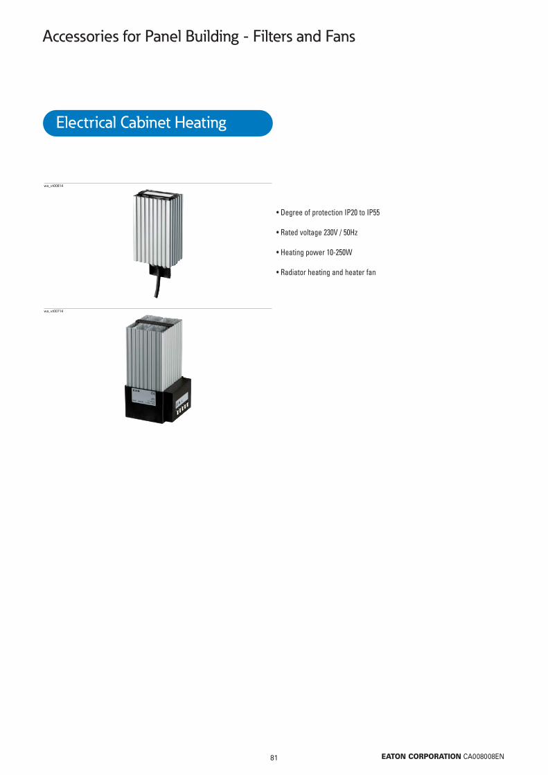
81 EATON CORPORATION CA008008EN
Accessories for Panel Building - Filters and Fans
• Degree of protection IP20 to IP55
• Rated voltage 230V / 50Hz
• Heating power 10-250W
• Radiator heating and heater fan
wa_vt00814
wa_vt00714
Electrical Cabinet Heating

82 EATON CORPORATION CA008008EN
Accessories for Panel Building - Filters and Fans
Radiator heating
45 105 65x70x50 R-HEAT-45W 167269 1100 130 140x70x50 R-HEAT-100W 167271 1150 150 215x70x50 R-HEAT-150W 167272 1
wa_vt00514
Heating Max. Radiator Type Article No. Packpower surface size designation (pcs.)[W] temperature H/W/D
[°C] [mm]
• Degree of protection IP44• Suitable for permanent operation• Any mounting position, preferably vertical• Aluminium profile, bright anodized• Rated voltage 230V / 50Hz• Snap-on mounting onto mounting rail
Radiator heating with limited surface temperature
20 55 1) 95x70x50 R-SHEAT-20W 167276 130 55 1) 140x70x50 R-SHEAT-30W 167277 150 55 1) 215x70x50 R-SHEAT-50W 167278 1
wa_vt00814
Heating Max. Radiator Type Article No. Packpower surface size designation (pcs.)[W] temperature H/W/D
[°C] [mm]
• Low surface temperature• Degree of protection IP44• Suitable for permanent operation• Any mounting position, preferably vertical• Aluminium profile, bright anodized• Rated voltage 230V / 50Hz• Snap-on mounting onto mounting rail
Note:1) Surface temperature at maximal Enclosure inside temperature of +35°C
Miniature radiator heating
10 95 45x50x29.5 R-MHEAT-10W 167273 120 115 45x50x29.5 R-MHEAT-20W 167274 130 140 45x75x29.5 R-MHEAT-30W 167275 1
wa_vt11514
Heating Max. Radiator Type Article No. Packpower surface size designation (pcs.)[W] temperature H/W/D
[°C] [mm]
• For use in small enclosures• Degree of protection IP54• Suitable for permanent operation• Any mounting position, preferably vertical• Aluminium profile, black anodized• Rated voltage 230V / 50Hz• Snap-on mounting onto mounting rail

83 EATON CORPORATION CA008008EN
Accessories for Panel Building - Filters and Fans
Fan heater
250 70 186.5x85x104 F-HEAT-250W 167279 1wa_vt00714
Heating Max. Radiator Type Article No. Packpower surface size designation (pcs.)[W] temperature H/W/D
[°C] [mm]
• Optimal for use in large electrical cabinets• Degree of protection IP20• Suitable for permanent operation• Any mounting position, preferably vertical• Aluminium profile, bright anodized• Rated voltage 230V / 50Hz• Snap-on mounting onto mounting rail

Accessories for Panel Building - Filters and Fans
84 EATON CORPORATION CA008008EN
Radiator heating• To avoid high levels of air humidity or levels of temperature that are too low• Power of 45-150W• Easy to install thanks to snap-on fitting
Technical Data
Dimensions (mm)
R-HEAT-45W R-HEAT-100W R-HEAT-150W
Heating power 45W 100W 150WMax. surface temperature 105°C 130°C 150°CPower consumption 45W 100W 150WSwitch-on current 1.8A 5.0A 7.5ADegree of protection IP44 IP44 IP44Weight 250g 510g 770gRated voltage 230V AC 50Hz / 60HzOperating range 110V-250V AC 50Hz /60HzPermanent operation 100%Temperature range for operation -40 ... +70°C (-40 ... +158°K)Temperature range for storage -40 ... +70°C (-40 ... +158°K)Mounting position any, preferably vertical Device design Aluminium profile, bright anodizedInstallation type Snap-on fixing for 35 mm profile rail acc. to EN 60715Protection class IType of connection Connection cable (500mm)
X
Y1
Z
Y2
L
mm R-HEAT-45W R-HEAT-100W R-HEAT-150WX 70 70 70Y1 65 140 215Y2 35 35 35Z 50 50 50L 500 500 500

85 EATON CORPORATION CA008008EN
Accessories for Panel Building - Filters and Fans
Note:1) Surface temperature at maximal Enclosure inside temperature of +35°C
Radiation Heaters with limitation of surface temperatures • Low surface temperature • Power of 20-50W• Easy to mount thanks to snap-on fixing
Technical Data
Dimensions (mm)
R-SHEAT-20W R-SHEAT-30W R-SHEAT-50W
Heating power 20W 30W 50WMax. surface temperature 1) 55°C 55°C 55°CPower consumption 20W 30W 50WSwitch-on current 1,1A 1,2A 2,3ADegree of protection IP44 IP44 IP44Weight 320g 450g 770gRated voltage 230V AC 50Hz / 60HzOperating range 110V-250V AC 50Hz /60HzPermanent operation 100%Temperature range for operation -40 ... +70°C (-40 ... +158°K)Temperature range for storage -40 ... +70°C (-40 ... +158°K)Mounting position any, preferably verticalDevice design Aluminium profile, bright anodized Installation type Snap-on fixing for 35 mm profile rail acc. to EN 60715Protection class IType of connection Connection cable (500mm)
mm R-SHEAT-20W R-SHEAT-30W R-SHEAT-50WX 70 70 70Y1 95 140 215Y2 37 37 37Z 50 50 50L 500 500 500
X
Y1
Z
Y2
L

86 EATON CORPORATION CA008008EN
Accessories for Panel Building - Filters and Fans
Miniature Radiator Heaters• For use in small enclosures• Power from 10-30W• Easy to mount thanks to snap-on fixture
Technical Data
Dimensions (mm)
R-MHEAT-10W R-MHEAT-20W R-MHEAT-30W
Heating power 10W 20W 30WMax. surface temperature 95°C 115°C 140°CPower consumption 10W 20W 30WSwitch-on current 1.0A 1.1A 1.2ADegree of protection IP54 IP54 IP54Weight 85g 120g 120gRated voltage 230V AC 50Hz / 60HzOperating range 110V-250V AC 50Hz /60HzPermanent operation 100%Temperature range for operation -40 ... +70°C (-40 ... +158°K)Temperature range for storage -40 ... +70°C (-40 ... +158°K)Mounting position any, preferably verticalDevice design Aluminium profile, black anodizedMounting type Snap-on fixing for 35 mm profile rail acc. to EN 60715Protection class IIType of connection Connection cable (300mm)
Y
X
Z
L
mm R-MHEAT-..WX 29,5Y 45Z 50L 300

87 EATON CORPORATION CA008008EN
Accessories for Panel Building - Filters and Fans
Fan Heaters• Optimal for use in large electrical cabinets • Power 250W• Easy to mount thanks to snap-on fixture
Technical Data
Dimensions (mm)
F-HEAT-250W
Heating power 250WMax. surface temperature 70°CPower consumption 260WSwitch-on current 2.2 ADegree of protection IP20Weight 1.035gAir flow 50m3/h (50Hz) / 61m3/h (60Hz)Rated voltage 230V AC 50Hz / 60HzOperating range 207-258V AC 50Hz /60HzPermanent operation 100%Temperature range for operation -40 ... +70°C (-40 ... +158°K)Temperature range for storage -40 ... +70°C (-40 ... +158°K)Mounting position any, preferably verticalDevice design Aluminium profile, bright anodizedInstallation type Snap-on fixing for 35 mm profile rail acc. to EN 60715Protection class IType of connection Connection cable (500mm)
mm F-HEAT-250WX 85Y1 186,5Y2 90Y3 65Z 104

88 EATON CORPORATION CA008008EN
Accessories for Panel Building
Cable Gland for Ventilation IP69K
M20 20.5 6-13 H05VV-F4x2,5/3x4mm2, V-M20-VENT 120814 1NYM 5x1,5/5x2,5mm2
Cable Hole Outer Cable Use of Cable Type Article No Units perInsertion Diameter Diameter NYM/NYY, 4-wire Designation package
mm mm mm2 (pcs.)
VT02610
• Colour RAL 7035
Ventilation grommet with filter disc, metric or PG
M25 25.5 KT-M25F 224556 50PG16 23.5 KT16F 024404 100
Cable Insertion Hole Diameter Type Article No Units permm Designation package (pcs.)
VT06608
• For use at the bottom or side of the enclosures, PE and PVC• Colour RAL 7035
Cable Gland for Ventilation IP56
M20 20.5 STB-M20F 224557 20M25 25.5 STB-M25F 224558 20
Cable Insertion Hole Diameter Type Article No Units permm Designation package (pcs.)
VT05808
• For use at the bottom or side of the enclosures, polyamide, halogen-free• Permeable to air, non-permeable to dust• To prevent condensation of water• Colour RAL 7035
Pressure Compensation Gland, IP66, metric
M40x1.5 DAV-M40 107225 2
Cable Insertion Type Article No Units per Designation package (pcs.)
VT33209
• Colour RAL 7035

89 EATON CORPORATION CA008008EN
Accessories for Panel Building
Pressure Compensation Gland, IP55, PG
PG29 DA412 079219 2
Cable Insertion Type Article No Units per Designation package (pcs.)
VT01612
• Colour RAL 7035

Eaton is a power management company with 2014 sales of $22.6 billion. Eaton provides energy-effi cient solutions that help our customers effectively manage electrical, hydraulic and mechanical power more effi ciently, safely and sustainably. Eaton has approximately 99,000 employees and sells products to customers in more than 175 countries.
For more information, visit www.eaton.eu.
Eaton Industries (Austria) GmbH
Scheydgasse 421210 WienAustria
To contact an Eaton salespersonor local distributor/agent, please visitwww.eaton.eu/electrical/customersupport
Eaton Industries Manufacturing GmbH
EMEA Headquarters
Route de la Longeraie1110 MorgesSwitzerland
© 2015 Eaton Industries (Austria) GmbHSubject to technical modifi cations. No responsibility is taken for misprints or errata.Printed in Austria (11/15)Publication number CA008008EN
Grafi cs: SRADigiPics, Lithos: Print:
4015081784929
Artic
le n
umbe
r 184
454


![[XLS] · Web viewANEL DA TAMPA REGULAGEM VALVULA - XL250R/TDM/XT225 ANEL DA TAMPA REGULAGEM VALVULA - XLX 250 R ANEL DA VARETA DE OLEO - CG/ML/TUR/NX/BIZ/TW ANEL DE VEDACAO 15,6 X](https://img.pdfslide.us/doc/110x75/5b18cf9c7f8b9a46258c062f/xls-web-viewanel-da-tampa-regulagem-valvula-xl250rtdmxt225-anel-da-tampa.jpg)