Embed Size (px)
Citation preview
Powertrain Thermal Modeling A. Oberting, Dr.-Ing. M. Auerbach, Dr.-Ing. S. Grams,
Prof. Dr.-Ing. Michael Bargende
20.10.2014
2 Powertrain Thermal Modeling | A. Oberting | 20.10.2014
Thermal behavior of hybrid powertrains
Cooperation-Professorship: Prof. Dr.-Ing. Michael Bargende Postgraduate: Hr. Andreas Oberting
Department: Powertrain Concepts Modeling & Simulation Projekt Manager Audi: Dr.-Ing. Michael Auerbach
3 Powertrain Thermal Modeling | A. Oberting | 20.10.2014
Outline
► Motivation of Hybrid Powertrain Simulation
► Strategy of a Modular Simulation System
► Powertrain Thermal Modeling
► Thermal Engine Models
► Lubrication Models
► Conclusion & Outline
4 Powertrain Thermal Modeling | A. Oberting | 20.10.2014
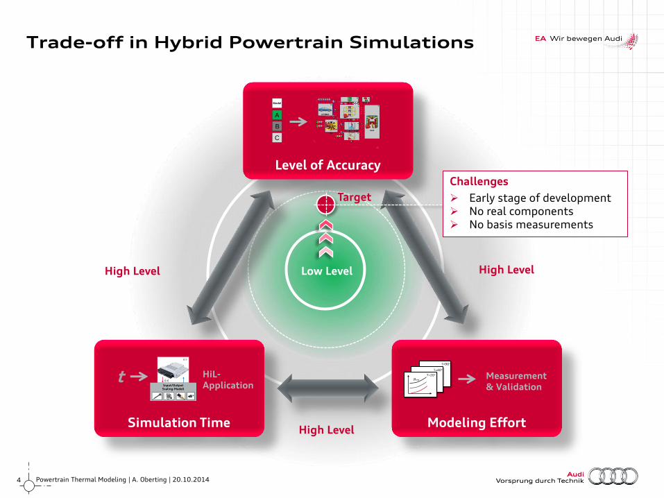
Trade-off in Hybrid Powertrain Simulations
High Level
Level of Accuracy
Modeling Effort Simulation Time
Input/Output Scaling-Modell
AI
ECU
HiL- Application
Measurement & Validation
t T=20°
T=40°
T=90°
pmr
Model
A
B
C
Low Level
Target
High Level
Challenges
Early stage of development No real components No basis measurements
High Level
5 Powertrain Thermal Modeling | A. Oberting | 20.10.2014
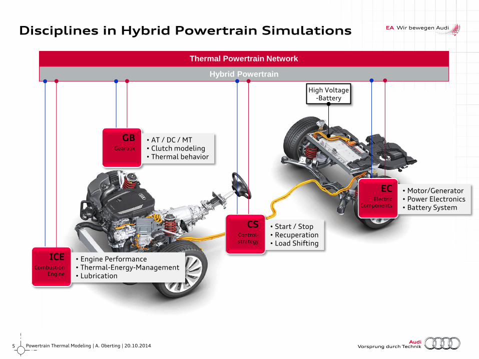
Thermal Powertrain Network
Hybrid Powertrain
Disciplines in Hybrid Powertrain Simulations
High Voltage -Battery
EC Electric
Components
• Motor/Generator • Power Electronics • Battery System
CS Control- strategy
• Start / Stop • Recuperation • Load Shifting
GB Gearbox
• AT / DC / MT • Clutch modeling • Thermal behavior
ICE Combustion
Engine
• Engine Performance • Thermal-Energy-Management • Lubrication
6 Powertrain Thermal Modeling | A. Oberting | 20.10.2014
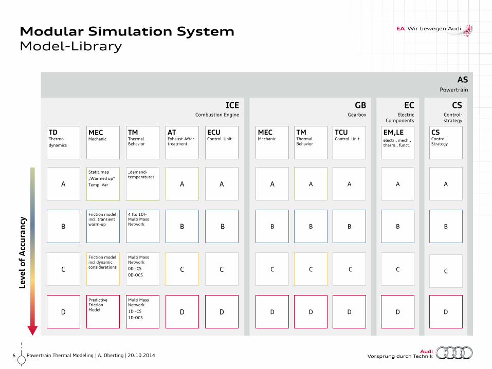
AS Powertrain
ICE Combustion Engine
GB Gearbox
EC Electric
Components
CS Control- strategy
Modular Simulation System Model-Library
TD Thermo-
dynamics
AT Exhaust-After-treatment
ECU Control Unit
MEC Mechanic
TM Thermal Behavior
TCU Control Unit
MEC Mechanic
TM Thermal Behavior
EM,LE electr., mech., therm., funct.
CS Control- Strategy
A A
4 (bis 10)- Massen- Netzwerk mit Rückkopplung B B
Reibmodell n-Führungs- Temperaturen
Trägheit
Mehrmassen- Netzwerk
0D–KKL
0D-ÖKL C C
Prädiktives Reibmodell
(detaillierte Mechanik)
Trägheit
Mehrmassen- Netzwerk
1D –KKL
1D-ÖKL D D
Reibkennfelder
Trägheit
Temperatur- Vorgabe
Reibmodell 1-Führungs- Temperatur
Trägheit
A
C
B
D D
C
A A
D
B B
C
A
B
C
D
A
B
C
D
A
B
C
D
Le
ve
l o
f A
ccu
ran
cy
A
B
C
D
MEC Mechanic
TM Thermal Behavior
4 (to 10)- Multi Mass Network
Friction model incl dynamic considerations
Multi Mass Network
0D –CS
0D-OCS
Predictive Friction Model
Multi Mass Network
1D –CS
1D-OCS
Static map
„Warmed up“
Temp. Var
„demand- temperatures
Friction model incl. transient warm-up
7 Powertrain Thermal Modeling | A. Oberting | 20.10.2014
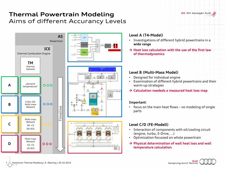
AS Powertrain
ICE Internal Combustion Engine
Thermal Powertrain Modeling Aims of different Accurancy Levels
Temperatur- Vorgabe
4 (bis 10)- Multi mass
Network
Multi mass Network
0D –CS
0D-OCS
Multi mass Network
1D –CS
1D-OCS
TM thermal
behavior
„demand- temperatures“
Motormasse
Kühlkreislauf
Öl (therm. Masse)
Luft
Kraftstoff
Abgas
Wandwärmeverluste
kWQW
A
B
C
D
Tim
eli
ne
Level A (T4-Model)
• Investigations of different hybrid powertrains in a wide range
Heat loss calculation with the use of the first law of thermodynamics
Level B (Multi-Mass Model)
• Designed for individual engine • Examination of different hybrid powertrains and their
warm-up strategies
Calculation neededs a measured heat loss map
Important:
• focus on the main heat flows – no modeling of single parts
Level C/D (FE-Modell)
• Interaction of components with oil/cooling circuit (engine, turbo, E-Drive, …)
• Optimization focussed on whole powertrain
Physical determination of wall heat loss and wall temperature calculation
8 Powertrain Thermal Modeling | A. Oberting | 20.10.2014
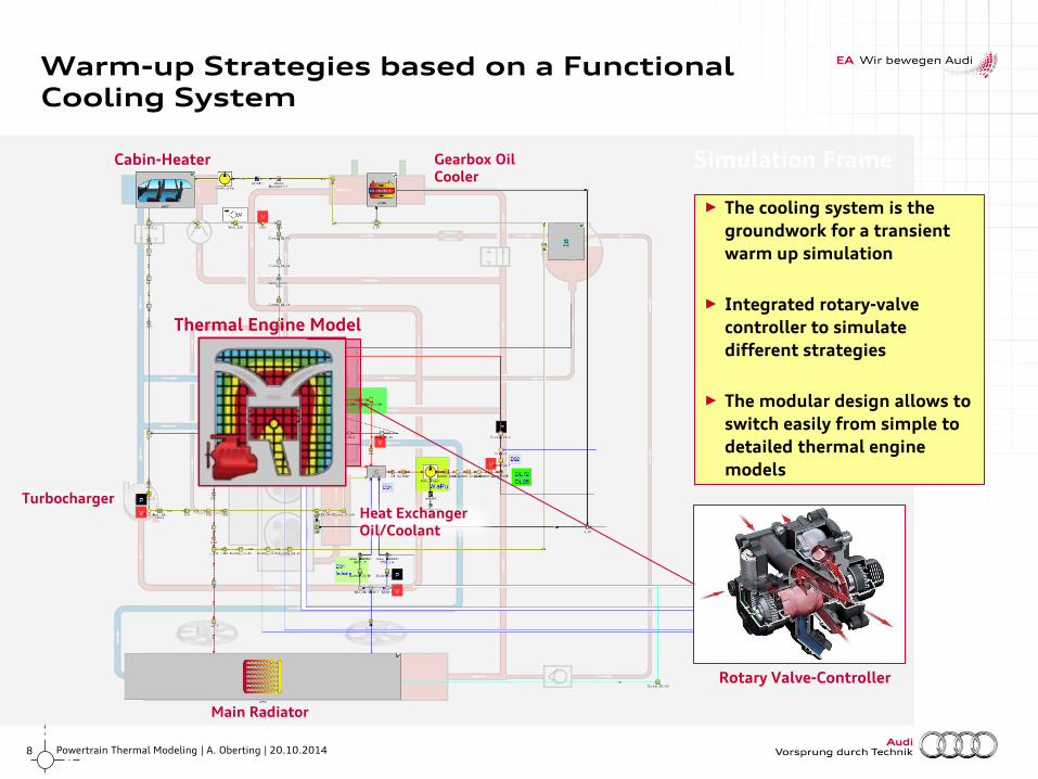
Warm-up Strategies based on a Functional Cooling System
Simulation Frame Cabin-Heater
Turbocharger
Main Radiator
► The cooling system is the
groundwork for a transient
warm up simulation
► Integrated rotary-valve
controller to simulate
different strategies
► The modular design allows to
switch easily from simple to
detailed thermal engine
models
Heat Exchanger Oil/Coolant
Thermal Engine Model
Rotary Valve-Controller
Gearbox Oil Cooler
9 Powertrain Thermal Modeling | A. Oberting | 20.10.2014
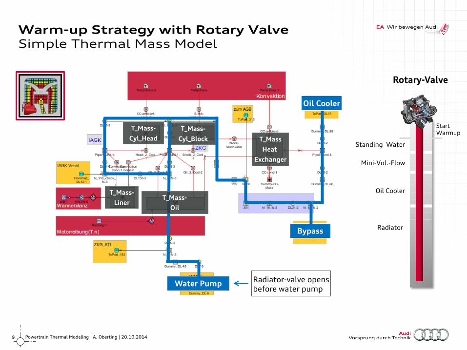
Warm-up Strategy with Rotary Valve Simple Thermal Mass Model
Standing Water
Mini-Vol.-Flow
Oil Cooler
Radiator Bypass
T_Mass-
Cyl_Head
T_Mass-
Cyl_Block T_Mass
Heat
Exchanger
Water Pump
T_Mass-
Oil
Oil Cooler
Start Warmup
Radiator-valve opens before water pump
T_Mass-
Liner
Rotary-Valve
10 Powertrain Thermal Modeling | A. Oberting | 20.10.2014
0 50 100 150 200 250 300 350 400 450 500 550 600
Zeit [s]
Te
mp
era
tur
[°C
]
0
10
20
30
40
50
60
70
80
90
100
110
120
Dre
hsch
iebe
r [°
]
40
60
80
100
120
140
160
180
200
T-OIL gemessen
T-OIL Steuergerät
T-OIL Filtersimulierte Öltemperatur
Drehschieber
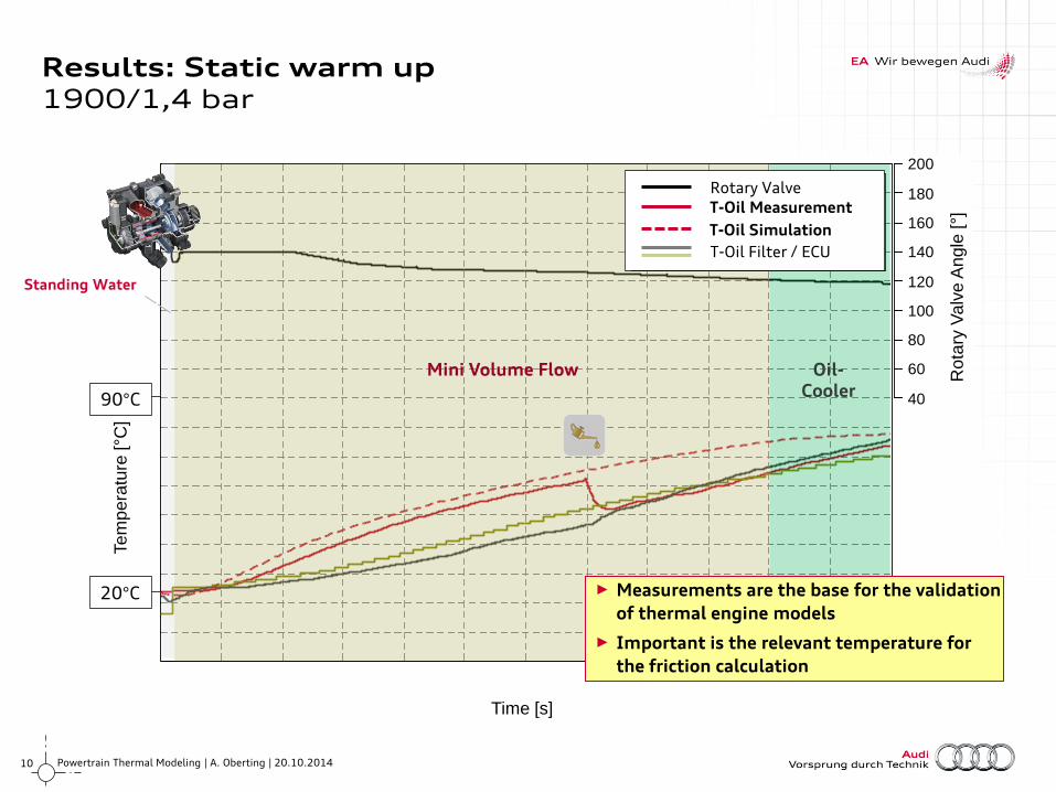
Results: Static warm up 1900/1,4 bar
Standing Water
Mini Volume Flow Oil- Cooler
Rota
ry V
alv
e A
ngle
[°]
Te
mp
era
ture
[°C
]
Rotary Valve
T-Oil Measurement
T-Oil Simulation
T-Oil Filter / ECU
Time [s]
20°C
90°C
► Measurements are the base for the validation
of thermal engine models
► Important is the relevant temperature for
the friction calculation
11 Powertrain Thermal Modeling | A. Oberting | 20.10.2014
Te
mp
era
tur
[°C
]
20
30
40
50
60
70
80
90
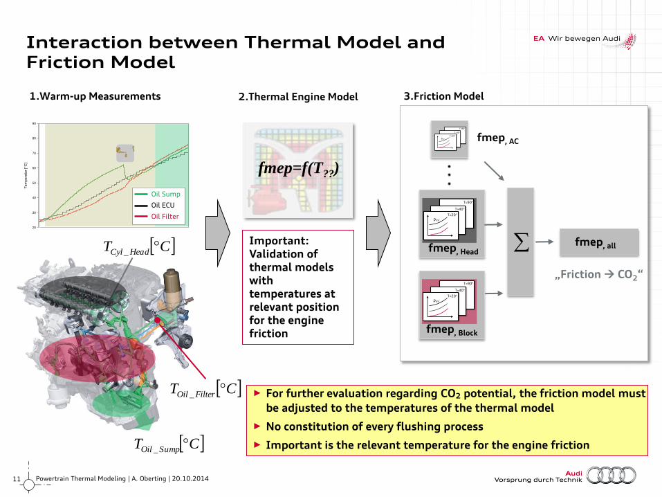
Interaction between Thermal Model and Friction Model
CT FilterOil _
CT HeadCyl _
Oil Filter
Oil ECU
Oil Sump
T=20°
T=40°
T=90°
pmr
T=20°
T=40°
T=90°
pmr
fmep, Head
T=20°
T=40°
T=90°
pmr
fmep, Block
„Friction CO2“
fmep, all
1.Warm-up Measurements
CT SumpOil _
fmep, AC
3.Friction Model
fmep=f(T??)
2.Thermal Engine Model
► For further evaluation regarding CO2 potential, the friction model must
be adjusted to the temperatures of the thermal model
► No constitution of every flushing process
► Important is the relevant temperature for the engine friction
Important: Validation of thermal models with temperatures at relevant position for the engine friction
Oil Filter
Oil ECU
Oil Sump
12 Powertrain Thermal Modeling | A. Oberting | 20.10.2014
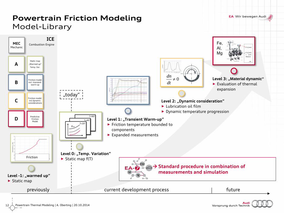
ICE Combustion Engine
Powertrain Friction Modeling Model-Library
previously current development process future
Level -1: „warmed up“ ► Static map
Level 1: „Transient Warm-up“ ► Friction temperature bounded to
components ► Expanded measurements
Level 3: „Material dynamic“
► Evaluation of thermal
expansion
Level 0: „Temp. Variation“ ► Static map f(T)
T=20°
T=40°
T=90°
pmr
Level 2: „Dynamic consideration“ ► Lubrication oil film ► Dynamic temperature progression
Friction model incl. transient
warm-up
Friction model incl dynamic
considerations
Predictive Friction Model
MEC Mechanic
Static map
„Warmed up“
Temp. Var. A
B
C
D
Standard procedure in combination of measurements and simulation
„today“
Re
ibm
itte
ldru
ck p
mr [N
m]
0.2
0.4
0.6
0.8
1.0
1.2
1.4
1.6
Temperatur [°C]
0 1000 2000 3000 4000 5000 6000 7000
Schleppmessung bei 90°CFriction
D2 [mm]
s [m]
D1 [mm]
… etc.
Material
Fe,
Al,
Mg
3_EF
FMO
M3
[Nm
]
-20
-18
-16
-14
-12
-10
-8
-6
-4
-2
0
2
4
6
8
10
3_DRZ3 [1/min]
0 20 40 60 80 100 120 140 160 180 200-1000
0
1000
2000
3000
4000
5000
6000
0dt
dn
13 Powertrain Thermal Modeling | A. Oberting | 20.10.2014
Re
ibm
om
en
t M
R [
Nm
]0
2
4
6
8
10
12
14
16
18
20
22
Drehzahl [1/min]
500 1000 1500 2000 2500 3000 3500 4000 4500 5000
Nebenaggregate Vakuumpumpe Kraftstoffpumpe HDP Ölpumpe Wasserpumpe Ventiltrieb Triebwerk
Re
ibm
om
en
t M
R [
Nm
]
0
2
4
6
8
10
12
14
16
18
20
22
Drehzahl [1/min]
500 1000 1500 2000 2500 3000 3500 4000 4500 5000
Nebenaggregate Vakuumpumpe Kraftstoffpumpe HDP Ölpumpe Wasserpumpe Ventiltrieb Triebwerk
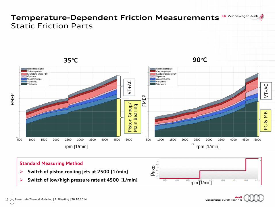
Temperature-Dependent Friction Measurements Static Friction Parts
35°C 90°C
pK
KD
rpm [1/min]
VT
+A
C
PG
& M
B
VT
+A
C
FM
EP
FM
EP
Pis
ton
Gro
up
/ M
ain
Be
ari
ng
rpm [1/min] rpm [1/min] rpm [1/min]
Standard Measuring Method
Switch of piston cooling jets at 2500 [1/min]
Switch of low/high pressure rate at 4500 [1/min]
14 Powertrain Thermal Modeling | A. Oberting | 20.10.2014
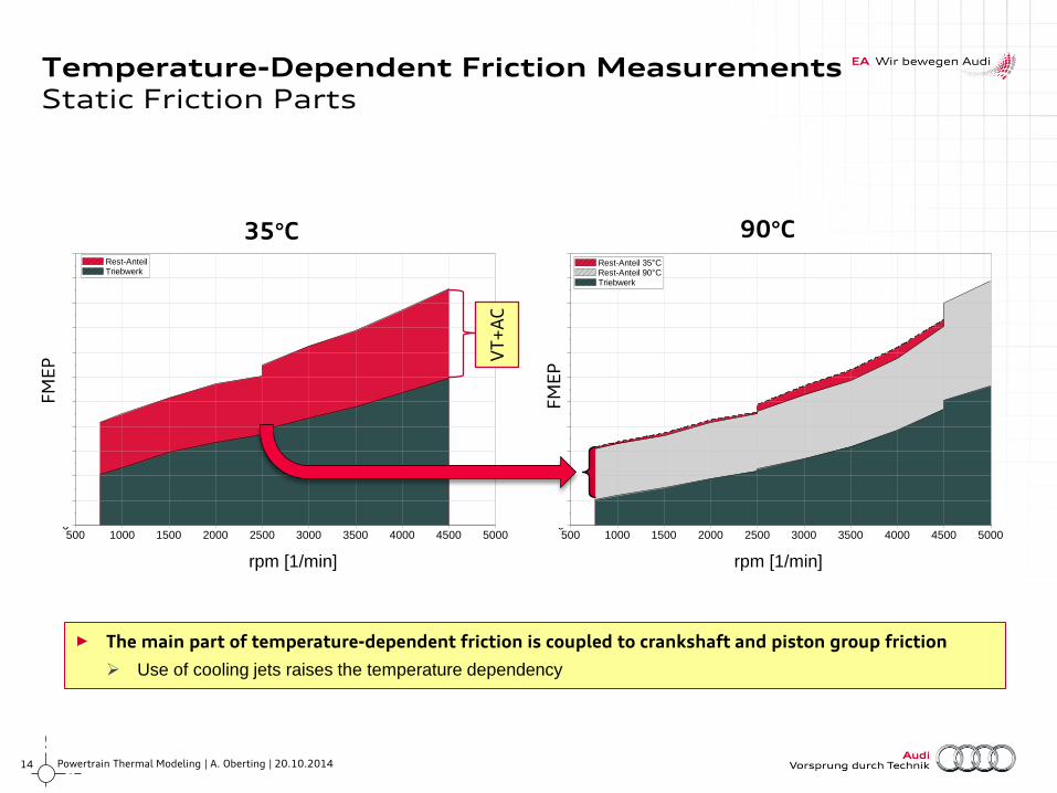
► The main part of temperature-dependent friction is coupled to crankshaft and piston group friction
Use of cooling jets raises the temperature dependency
Re
ibm
om
en
t M
R [
Nm
]0
2
4
6
8
10
12
14
16
18
20
22
Drehzahl [1/min]
500 1000 1500 2000 2500 3000 3500 4000 4500 5000
Rest-Anteil 35°C Rest-Anteil 90°C Triebwerk
Re
ibm
om
en
t M
R [
Nm
]
0
2
4
6
8
10
12
14
16
18
20
22
Drehzahl [1/min]
500 1000 1500 2000 2500 3000 3500 4000 4500 5000
Rest-Anteil Triebwerk
Temperature-Dependent Friction Measurements Static Friction Parts
35°C 90°C
VT
+A
C
FM
EP
FM
EP
rpm [1/min] rpm [1/min]
15 Powertrain Thermal Modeling | A. Oberting | 20.10.2014
Te
mp
era
ture
[°C
]
FM
EP
[b
ar]
Time [s]
Te
mp
era
ture
[°C
]
FM
EP
[b
ar]
Time [s]
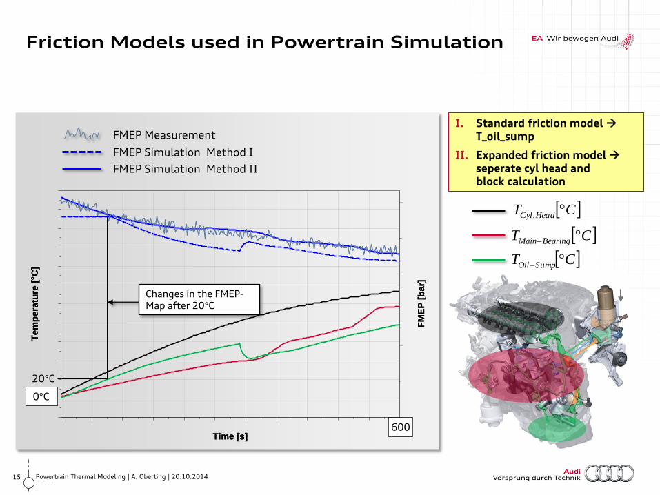
Friction Models used in Powertrain Simulation
CT BearingMain
CT HeadCyl ,
CT SumpOil
FMEP Simulation Method I
FMEP Measurement
FMEP Simulation Method II
Changes in the FMEP-Map after 20°C
0°C
600
20°C
I. Standard friction model T_oil_sump
II. Expanded friction model seperate cyl head and block calculation
16 Powertrain Thermal Modeling | A. Oberting | 20.10.2014
► To simulate the complexity in thermal behaviour of an internal combustion engine
detailed models are required
► Consequences for the thermal behavior of a hybrid powertrain model
► Simple approaches generate good results depending on
the application area e.g.: HiL, forecasts of CO2 Emission
► Identification and usage of friction-dependent temperatures for validation and
friction modeling main bearing & piston group
► Future Steps
► Combination of high level detailed thermal models and the hybrid powertrain
models
► Evaluation of split-cooling-concepts by separation of oil- and coolant-
temperatures in friction modeling
Conclusion & Outlook

Thank You.