Embed Size (px)
Citation preview
MK Series May 19, 2005 Pg. 1 of 14
MK Series, 130-225WInput Ranges : 240-420 VDC Output Voltage: Single Output 3.3V - 48V Dual Output +3.3V/+2.5V, +3.3V/+1.8V, +5.0V/+3.3V +5.0V/+2.5V +5.0V/+1.8V Triple Output +3.3V/+2.5V/+13V, +3.3V/+1.8V/+13V, +5.0V/+3.3V/+15V +5.0V/+2.5V/+15V, +5.0V/+1.8V/+15V Output Power: 130 to 225 W
MK series is a family of high power density, high efficiency, and high reliability DC-DC Converters. It provides up to 50W output in a 2.84” x 2.84” footprint. The wide input range of 240 to 390 vdc is ideal for unregulated input applications. Integral PCB transformer / inductor is used for all models in this series. This new design technique has greatly improved the magnetic coupling, reduced switching spike and provided performance consistency. It also streamlines the production process by completely eliminating the hand-wind magnetic assembly process from production lines.
MK series provides the most extensive protection to safeguard both the power converter and the load. It includes output over-voltage protection, over-current protection, hiccup mode indefinite short circuit protection and under-voltage lockout. Over-current inception point is set at about 115% of rated load. Hiccup mode cycles for 28mSec periods with 3mSec on and 25mSec off. Over-temperature shutdown, activated at +105°C of board temperature, will recover when the temperature falls below +95°C.
MK series features low output noise, very tight line and load regulation, and high efficiency. No external capacitor requirement for normal operation.
FEATURES General: • Small Footprint : 2.84” x 2.84” • High Output Power : to 225 watts • Current Sharing • Synchronization : Input & Output • Wide Input Range : 240-420Vdc • Encapsulated with Metal Case • Integral PCB Transformer • High Conversion Efficiency to 91% • Line & Load Regulation to ±0.5% • Fixed Operating Frequency Protection: • Output Over-Voltage Protection • Output Over-Load Protection • Hiccup Mode Short Circuit protection • Over-Temperature Protection • Input Under-Voltage Lock-Out Control: • Enable (On/Off) Control • Output Voltage Trim Isolation: • Isolation Voltage > 1500V
TABLE OF CONTENTS :General Specifications .................................................................................................. 2Single Output ................................................................................................................ 4Dual Output ................................................................................................................ 10Triple Output ............................................................................................................... 12
PowerstaxDC-DC CONVERTERS
Powerstax plc. www.powerstaxplc.com
2 of 14
ACONDC-DC CONVERTERS
TM
2. Input SpecificationsParameter Conditions / Description Min Nom Max Units
Input VoltageVoltage Range(Continuous) 240 300 420 Vdc
Under-Voltage Lockout (UVLO)Turn-On Threshold
(Ramping Up) 235 Vdc
Turn-Off Threshold(Ramping Down) 230 Vdc
1. Absolute Maximum Ratings Stresses in excess of the absolute maximum ratings can cause performance degradation, adversely effect longterm reliability, and cause permanent damage to the device.
Parameter Conditions / Description Min Max UnitsInput Voltage
Continuous -0.3 420 VdcTransient -0.3 430 Vdc
Operating Temperature All models, base plate temperature -40 +105 °CStorage Temperature Ambient -55 +125 °CIsolation Voltage Input to Output +2000 Vdc
6. Output SpecificationsParameter Conditions / Description Min Nom Max Units
Voltage Accuracy Please see table %Output Current Please see table AdcOutput Trim ±10 %VoutOver Voltage Protection 15 %VdcLine Regulation 0.1 %VoutLoad Regulation 0.2 %VoutTransient Respoonse 50% ± 25% step load change 400 µSec.Ripple & Noise Please see table mVp-pSwitching Frequency 300 KHz
3. Enable (On-Off Control)Parameter Conditions / Description Min Nom Max Units
Enable Pin Open Circuit Voltage 10 Vdc Source Current Enable pin is connected to -Vin 1 mAPositive Logic Standard On-Control (or Floating Enable Pin) 2.5 10 Vdc Off-Control -0.5 1.8 Vdc
4. Sync-InParameter Conditions / Description Min Nom Max Units
Clock Amplitude 4.0 6.0 VdcClock Pulse Width 0.5 1 µSec.Capture Frequency Range 270 340 KHz
5. I-ShareParameter Conditions / Description Min Nom Max Units
Forced Current Share Accuracy % of Output Rated Current 10 %A
7. Sync-OutParameter Conditions / Description Min Nom Max Units
Interface Open Collector Voltage 20 Vdc Current 10 mA
MK Series, 150W
Powerstax plc. www.powerstaxplc.com
3
11. Environmental and Mechanical SpecificationsParameter Conditions / Description Min Nom Max Units
Operating Temperature Standard -25 +105 °C Extended -55 +105 °CStorage Temperature -55 +125 °CTemperature Coefficient ±0.02 %/°CShock Halfsine wave, 3 axes 50 gSinusoidal Vibration GR-63-CORE, Section 5.4.2 1 gHumidity Relative Humidity, Non-Condensing 95 %R.H.Weight 5.8(165) Oz(g)MTBF (calculated) Bellcore TR-NWT-000332 method 1 - parts count 1 MHrs
10. Output TrimParameter Conditions / Description Min Nom Max Units
Negative Trim Standard Trim Up Trim Pin to (-)Sense 10 %Vdc Trim Down Trim Pin to (+)sense 5 %VdcPositive Trim Not Available
12. Isolation SpecificationsParameter Conditions / Description Min Nom Max Units
Isolation Voltage Input to Output 1500 Vdc I/O to Case 1000 VdcIsolation Resistance Input to Output 10 MΩIsolation Capacitance Input to Output 3 nF
13. ProtectionsParameter Conditions / Description Min Nom Max Units
Over-Load Protection Type Current-Mode, Pulse by Pulse Current Limit Threshold % Rated Load 120 %Short-Circuit Protection Type Hiccup Mode, Non-Latching, Auto-Recovery Threshold Short-Circuit Resistance 65 mΩOver-Temperature Protection Type Non-Latching, Auto-Recovery Threshold PCB Temperature 115 °C Hysteresis 15 °COver-Voltage Protection Type Auxiliary Feedback Loop Control Set-Point 120 %Vout
8. Power Good SignalParameter Conditions / Description Min Nom Max Units
Power Good Sense Level % of Rated Output Voltage 90 115 %VdcPower Good 5.0 VdcOutput Source Current 5.0 mA
8. FET DriveParameter Conditions / Description Min Nom Max Units
Drive Voltage Voltage above (+)Vout 7.5 VdcOutput Source Current 5.0 mA
MK Series, 150W
Powerstax plc. www.powerstaxplc.com
4
INPUT OUTPUT OverTemp.
Shutdown/Recover
EFF. (typ.) Pin-Out
MODEL NO.
Nominal(Range)
UVL(On/Off)
MaxPower(Watts)
Voltage (V) Current (A) Ripple & NoiseOVP
ShortCircuit
ProtectionSet
Point Min.* Max.* Min. Max. Peak-Peak R.M.S.
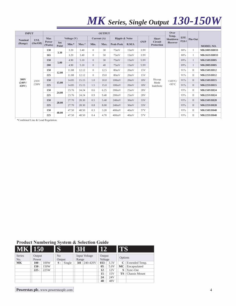
300V(240V/ 420V)
235V/230V
1303.30
3.20 3.40 0 30 75mV 15mV 3.9V
HiccupMode
Indefinite
+105°C/+95°C
88% I MK100S3H033
165 3.20 3.40 0 50 75mV 15mV 3.9V 88% I MK165S3H033
1505.00
4.90 5.10 0 30 75mV 15mV 5.9V 89% I MK150S3H05
200 4.90 5.10 0 40 75mV 15mV 5.9V 89% I MK200S3H05
15012.00
11.88 12.12 0 12.5 80mV 20mV 15V 91% II MK150S3H12
225 11.88 12.12 0 19.0 80mV 20mV 15V 91% II MK225S3H12
15015.00
14.85 15.15 1.0 10.0 100mV 20mV 18V 91% II MK150S3H15
225 14.85 15.15 1.5 15.0 100mV 20mV 18V 91% II MK225S3H15
15024.00
23.76 24.24 0.6 6.25 200mV 25mV 28V 93% II MK150S3H24
225 23.76 24.24 0.9 9.40 200mV 25mV 28V 93% II MK225S3H24
15028.00
27.70 28.30 0.5 5.40 240mV 30mV 33V 93% II MK150S3H28
225 27.70 28.30 0.8 8.00 240mV 30mV 33V 93% II MK225S3H28
15048.00
47.50 48.50 0.3 3.20 400mV 40mV 57V 93% II MK150S3H48
225 47.50 48.50 0.4 4.70 400mV 40mV 57V 93% II MK225S3H48
*Combined Line & Load Regulation.
MK Series, Single Output 130-150W
Product Numbering System & Selection GuideMK 150 S 3H 12 TSSeriesNo.
OutputPower
NoOutput
Input VoltageRange
OutputVoltage Options
MK 100 : 100W S : Single 3H : 240-420V 033 : 3.3V C : Extended Temp.150 : 150W 05 : 5.0V MC : Encapsulated225 : 225W 12 : 12V S : Sync-Out
15 : 15V TS : Chassis Mount24 : 24V48 : 48V
Powerstax plc. www.powerstaxplc.com
5
MK Series, Single Output 130-150W
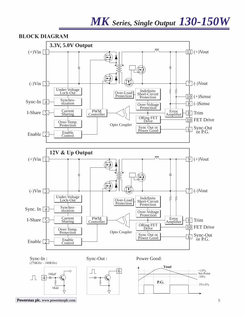
Sync-In :(270KHz ~ 340KHz)
100ρF
1KΩ
Vout
4
Sync-Out : Power Good:
Set-Point-10%
+15%
5V±5%P.G.
6
BLOCK DIAGRAM
(+)Vin 1 (+)Vout11
(-)Vout7
(+)Sense10(-)Sense8
Over-LoadProtection
Trim8ErrorAmplifier
FET Drive10Sync-Out or P.G.6
PWMController
IndefiniteShort-Circuit
Protection
Over-VoltageProtection
ORing FETDrive
Sync Out or Power Good
(-)Vin 3
Sync-In 4
I-Share 5
Enable 2
Under-VoltageLock-Out
Synchro-nization
CurrentSharing
Over-Temp.Protection
EnableControl
3.3V, 5.0V Output
Opto Coupler
(+)Vin 1 (+)Vout9
(-)Vout7
Over-LoadProtection
Trim8ErrorAmplifier
FET Drive10Sync-Out or P.G.6
PWMController
IndefiniteShort-Circuit
Protection
Over-VoltageProtection
ORing FETDrive
Sync Out or Power Good
(-)Vin 3
Sync. In 4
I-Share 5
Enable 2
Under-VoltageLock-Out
Synchro-nization
CurrentSharing
Over-Temp.Protection
EnableControl
12V & Up Output
Opto Coupler
Powerstax plc. www.powerstaxplc.comPowerstax plc. www.powerstaxplc.com
6
2.50(63.5)
2.84(72.2)
0.17(4.3)
2.25
(57.
2)
2.84
(72.
2)0.
295
(7.5
)
4 - Sync-In0.375(9.525)
0.375(9.525)
0.750(19.05)
0
0.500(12.70)
5 - I Share0.750(19.05)
3 - Vin(-)
2 - Enable
1 - Vin(+)
(-)Vout - 7
(+)Vout - 11
FET Drive - 12
0.800(20.32)Sync-Out/PG - *6
(-)Sense - 8Trim - 9
(+)Sense - 10
0.200(5.08)00.200(5.08)
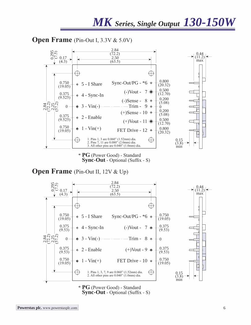
Open Frame (Pin-Out I, 3.3V & 5.0V)
0.800(20.32)
0.500(12.70)
1. Pins 1, 3 are 0.060” (1.52mm) dia.2. Pins 7, 11 are 0.080” (2.0mm) dia.3. All other pins are 0.040” (1.0mm) dia.
* PG (Power Good) - Standard Sync-Out - Optional (Suffix - S)
2.50(63.5)
2.84(72.2)
0.17(4.3)
2.25
(57.
2)
2.84
(72.
2)0.
295
(7.5
)
4 - Sync-In0.375(9.53)
0.375(9.53)
0.750(19.05)
0
0.375(9.53)
5 - I Share0.750(19.05)
3 - Vin(-)
2 - Enable
1 - Vin(+)
(-)Vout - 7
(+)Vout - 9
FET Drive - 10
0.750(19.05)Sync-Out/PG - *6
Trim - 8 0
1. Pins 1, 3, 7, 9 are 0.060” (1.52mm) dia.2. All other pins are 0.040” (1.0mm) dia.
Open Frame (Pin-Out II, 12V & Up)
0.750(19.05)
0.375(9.53)
* PG (Power Good) - Standard Sync-Out - Optional (Suffix - S)
0.44(11.2)max
0.15(3.8)min
0.44(11.2)max
0.15(3.8)min
MK Series, Single Output 130-150W
Powerstax plc. www.powerstaxplc.com
7
2.50(63.5)
3.00(76.2)
0.25(6.4)
2.25
(57.
2)
3.00
(76.
2)0.
375
(9.5
)
4 - Sync-In0.375(9.525)
0.375(9.525)
0.750(19.05)
0
0.500(12.70)
0.55(14.0)max
#4-4
0 TA
P, 4
PLA
CES
.
0.020(0.5)
5 - I Share0.750(19.05)
3 - Vin(-)
2 - Enable
1 - Vin(+)
(-)Vout - 7
(+)Vout - 11
FET Drive - 12
0.15(3.8)min
0.800(20.32)Sync-Out/PG - *6
(-)Sense - 8Trim - 9
(+)Sense - 10
0.200(5.08)00.200(5.08)
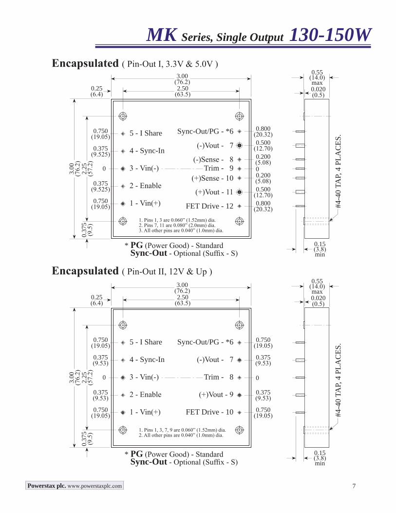
Encapsulated ( Pin-Out I, 3.3V & 5.0V )
0.800(20.32)
0.500(12.70)
1. Pins 1, 3 are 0.060” (1.52mm) dia.2. Pins 7, 11 are 0.080” (2.0mm) dia.3. All other pins are 0.040” (1.0mm) dia.
* PG (Power Good) - Standard Sync-Out - Optional (Suffix - S)
2.50(63.5)
3.00(76.2)
0.25(6.4)
2.25
(57.
2)
3.00
(76.
2)0.
375
(9.5
)
4 - Sync-In0.375(9.53)
0.375(9.53)
0.750(19.05)
0
0.375(9.53)
0.55(14.0)max
#4-4
0 TA
P, 4
PLA
CES
.
0.020(0.5)
5 - I Share0.750(19.05)
3 - Vin(-)
2 - Enable
1 - Vin(+)
(-)Vout - 7
(+)Vout - 9
FET Drive - 10
0.15(3.8)min
0.750(19.05)Sync-Out/PG - *6
Trim - 8 0
1. Pins 1, 3, 7, 9 are 0.060” (1.52mm) dia.2. All other pins are 0.040” (1.0mm) dia.
Encapsulated ( Pin-Out II, 12V & Up )
0.750(19.05)
0.375(9.53)
* PG (Power Good) - Standard Sync-Out - Optional (Suffix - S)
MK Series, Single Output 130-150W
Powerstax plc. www.powerstaxplc.com

8
0.37
5(9
.5)
5
4
3
2
1
6
7
8
9
10
I-Share
Sync-In
Enable
Vin(+)
Vin(-)
Sync-Out/PG
(+)Vout
(-)Vout
FET Drive
Trim
Chassis Mount ( Pin-Out II only, 12V & Up )
MK Series, Single Output 130-150W
EnableThis pin provides the remote On/Off control function. Two control logics are available: Positive & Negative. Positive logic turns the module ON during a logic high voltage on the enable pin, and OFF during a logic low. Negative logic turns the module OFF during a logic high and ON during a logic low. Positive logic is the standard factory configuration. Negative Enable Logic can be specified with suffix N. The Enable pin can be left floating if not used.
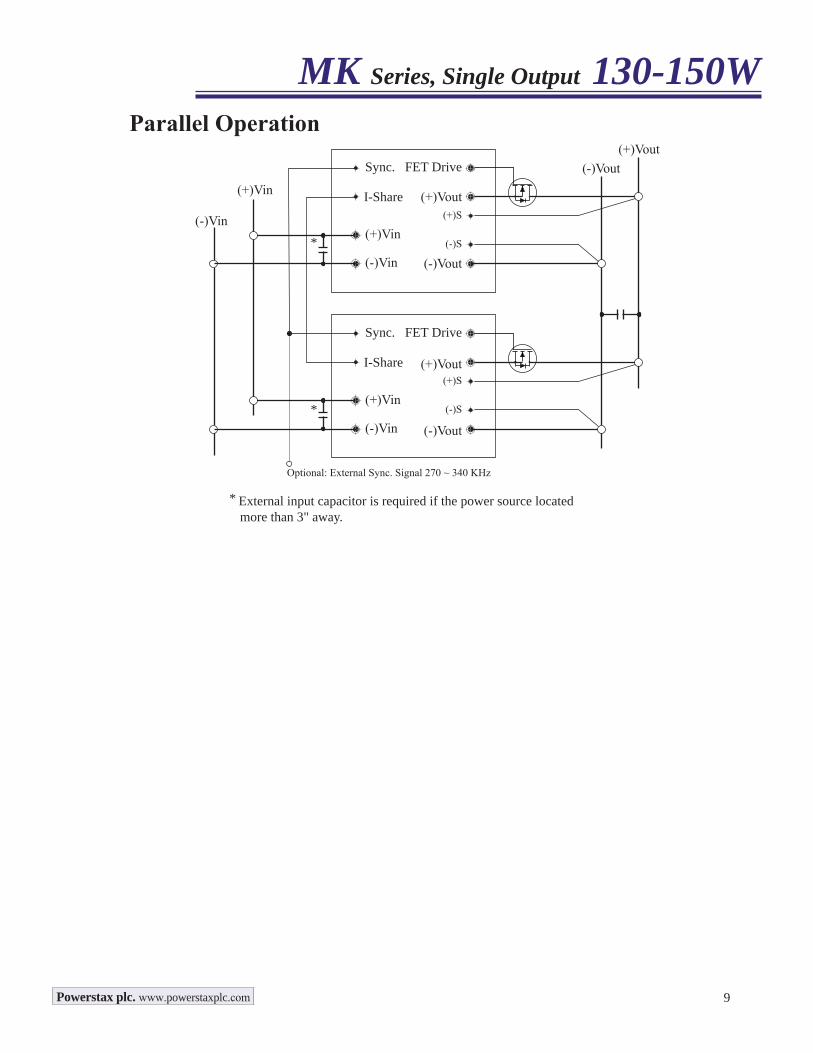
Sync-InThis pin can be connected either to external clock or directly to the Sync-In pin of another MKS, MKD or MKT module. If the Sync-In pin is connected to another module's Sync-In pin, the connection should be as direct as possible, and the Vin(-) pins of the modules must be shorted together. If an external clock signal is applied to the Sync-In pin, the signal must be a 300KHz (±30KHz) square wave with a ≥ 4 Vp-p amplitude. The Sync-In pin can be left floating if not used.
I-ShareTwo or more modules can be operated in parallel for either redundant operation or additional power requirements. Connect I-Share pin together will force load sharing between the connected modules. To implement forced load sharing, the Sync-In pins of all units must be connected together also. The I-Share pin can be left floating if not used.
Sync-OutThis pin contains a clock signal referenced to the (-)Vout pin. The frequency of this signal will equal either the module's internal clock frequency or the frequency established by an external clock applied to the Sync-In pin. The Sync-Out pin can be left floating if not used.
SenseRemote sensing allows the converter to sense the output voltage directly at the point of load and thus automatically compensates the load conductor distribution & contact losse. There is one sense lead for each output terminal, designated +Sense and -Sense. These leads carry very low current compared with the load leads. Internally a resistor is connected between sense terminal and power output terminal. If the remote sense is not used, the sense leads needs to be shorted to their respective output leads. Care has to be taken when making output connections. If the output terminals should disconnect before the sense lines, the full load current will flow down the sense lines and damage the internal sensing resistors. Be sure to always power down the converter before making any output connections. The maximum compensation voltage for line drop is up to 0.5V
TrimOutput voltage set-point can be increased or decreased by connecting a trimming resistor between trim pin and either the (+)Vout pin or the (-)Vout pin. The trim function is a negative logic. Connecting resistor from trim pin to (-)Vout will trim the voltage up. The trim pin can be left floating if not used.
#4-4
0 TA
P, 4
PLA
CES
.
Cha
ssis
Mou
nt (T
S Su
ffix)
2.50(63.5)
3.00(76.2)
0.25(6.4)
2.25
(57.
2)
3.00
(76.
2)0.98(25)max
Powerstax plc. www.powerstaxplc.com
9
FET Drive
(+)Vout
(+)Vin(+)S
(-)S
Sync.
I-Share
FET Drive
(+)S
(-)S
Sync.
I-Share
(+)Vin
* External input capacitor is required if the power source located more than 3" away.
Parallel Operation
Optional: External Sync. Signal 270 ~ 340 KHz
*
*
(-)Vin
(-)Vin
(+)Vin
(-)Vin
(-)Vout
(+)Vout
(-)Vout
(+)Vout(-)Vout
MK Series, Single Output 130-150W
Powerstax plc. www.powerstaxplc.com
INPUT OUTPUTOver
Temp.Protect
EFF. (typ.)
MODEL NO.
Nominal(Range)
UVLOOn/Off
Power(Watt)
Voltage (V) Current (A) Ripple & Noise ShortCircuit
Protection# Set Point Min.* Max.* # Min. Max. Peak-Peak R.M.S.
300(240 - 420)
230V/220V
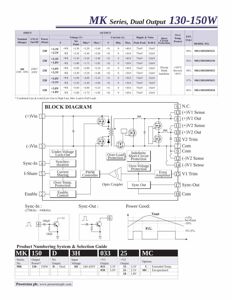
130 +3.3V+2.5V
+V1 +3.30 +3.20 +3.40 +I1 0 +40.0 75mV 15mV
HiccupMode
Indefinite
+105°CRecover +95°C
86% MK150D3H03325-V2 +2.50 +2.40 +2.60 +I2 0 +20.0 75mV 15mV
130 +3.3V+1.8V
+V1 +3.30 +3.20 +3.40 +I1 0 +40.0 75mV 15mV86% MK150D3H03318
-V2 +1.80 +1.75 +1.85 +I2 0 +20.0 75mV 15mV
150 +5.0V+3.3V
+V1 +5.00 +4.90 +5.10 +I1 0 +30.0 75mV 15mV88% MK150D3H05033
-V2 +3.30 +3.20 +3.40 +I2 0 +20.0 75mV 15mV
150 +5.0V+2.5V
+V1 +5.00 +4.90 +5.10 +I1 0 +30.0 75mV 15mV87% MK150D3H05025
-V2 +2.50 +2.40 +2.60 +I2 0 +20.0 75mV 15mV
150 +5.0V+1.8V
+V1 +5.00 +4.90 +5.10 +I1 0 +30.0 75mV 15mV86% MK150D3H05018
-V2 +1.80 +1.75 +1.85 +I2 0 +20.0 75mV 15mV
* Combined Line & Load (Low Line to High Line, Min. Load to Full Load)
Product Numbering System & Selection GuideMK 150 D 3H 033 25 MCSeriesNo.
OutputPower*
NoOutput
InputVoltage
+V1Output
+V2Output Options
MK 150 : 150W D : Dual 3H : 240-420V 033 : 3.3V 33 : 3.3V C : Extended Temp.050 : 5.0V 25 : 2.5V MC : Encapsulated
18 : 1.8V
MK Series, Dual Output 130-150W
Sync-In :(270KHz ~ 340KHz)
100ρF
1KΩ
Vout
4
Sync-Out : Power Good:
Set-Point-10%
+15%
5V±5%P.G.
6
(+)Vin 1 (+)V1 Out8(+)V2 Sense 11(+)V2 Out10
(+)V1 Sense 13
Com7
N.C.6
Com9(-)V2 Sense 12(-)V1 Sense 14
Over-LoadProtection
V1 Trim15ErrorAmplifier
Sync-Out17
Com18
PWMController
IndefiniteShort-Circuit
Protection
Over-VoltageProtection
Sync Out
(-)Vin 3
Sync-In 4
I-Share 5
Enable 2
Under-VoltageLock-Out
Synchro-nization
CurrentSharing
Over-Temp.Protection
EnableControl
V2 Trim16
BLOCK DIAGRAM
Opto Coupler
Powerstax plc. www.powerstaxplc.com
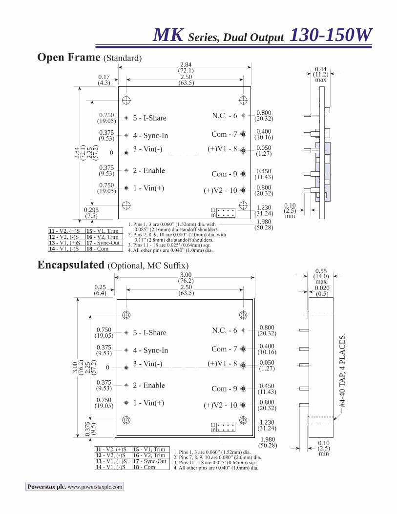
MK Series, Dual Output 130-150WOpen Frame (Standard)
0.44(11.2)max
0.10(2.5)min
1. Pins 1, 3 are 0.060” (1.52mm) dia.2. Pins 7, 8, 9, 10 are 0.080” (2.0mm) dia.3. Pins 11 - 18 are 0.025’ (0.64mm) sqr.4. All other pins are 0.040” (1.0mm) dia.
2.50(63.5)
3.00(76.2)
0.25(6.4)
2.25
(57.
2)
3.00
(76.
2)0.
375
(9.5
)
4 - Sync-In0.375(9.53)
0.375(9.53)
0.750(19.05)
0
0.55(14.0)max
#4-4
0 TA
P, 4
PLA
CES
.
0.020(0.5)
5 - I-Share0.750(19.05)
3 - Vin(-)
2 - Enable
1 - Vin(+)
Com - 9
(+)V2 - 10
0.10(2.5)min
0.800(20.32)N.C. - 6
0.800(20.32)
0.450(11.43)
(+)V1 - 8 0.050(1.27)
Com - 7 0.400(10.16)
1.230(31.24)11
18
11 - V2, (+)S 15 - V1, Trim12 - V2, (-)S 16 - V2, Trim13 - V1, (+)S 17 - Sync-Out14 - V1, (-)S 18 - Com
1. Pins 1, 3 are 0.060” (1.52mm) dia. with 0.085” (2.16mm) dia standoff shoulders.2. Pins 7, 8, 9, 10 are 0.080” (2.0mm) dia. with 0.11” (2.8mm) dia standoff shoulders.3. Pins 11 - 18 are 0.025’ (0.64mm) sqr.4. All other pins are 0.040” (1.0mm) dia.
2.50(63.5)
2.84(72.1)
0.17(4.3)
2.25
(57.
2)
2.84
(72.
1)
0.295(7.5)
4 - Sync-In0.375(9.53)
0.375(9.53)
0.750(19.05)
0
5 - I-Share0.750(19.05)
3 - Vin(-)
2 - Enable
1 - Vin(+)
Com - 9
(+)V2 - 10
0.800(20.32)N.C. - 6
0.800(20.32)
0.450(11.43)
(+)V1 - 8 0.050(1.27)
Com - 7 0.400(10.16)
1.230(31.24)1.980
(50.28)
1118
11 - V2, (+)S 15 - V1, Trim12 - V2, (-)S 16 - V2, Trim13 - V1, (+)S 17 - Sync-Out14 - V1, (-)S 18 - Com
1.980(50.28)
Encapsulated (Optional, MC Suffix)
Powerstax plc. www.powerstaxplc.com
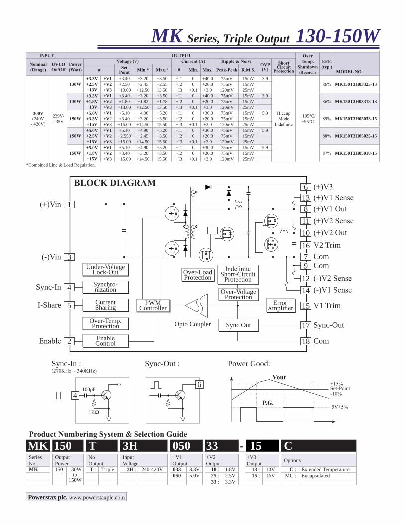
Product Numbering System & Selection GuideMK 150 T 3H 050 33 - 15 CSeriesNo.
OutputPower
NoOutput
InputVoltage
+V1Output
+V2Output
+V3Output Options
MK 150 : 130Wto
150W
T : Triple 3H : 240-420V 033 : 3.3V 18 : 1.8V 13 : 13V C : Extended Temperature050 : 5.0V 25 : 2.5V 15 : 15V MC : Encapsulated
33 : 3.3V
MK Series, Triple Output 130-150W
Sync-In :(270KHz ~ 340KHz)
100ρF
1KΩ
Vout
4
Sync-Out : Power Good:
Set-Point-10%
+15%
5V±5%P.G.
6
INPUT OUTPUT OverTemp.
Shutdown/Recover
EFF. (typ.)
MODEL NO.Nominal(Range)
UVLOOn/Off
Power(Watt)
Voltage (V) Current (A) Ripple & NoiseOVP(V)
ShortCircuit
Protection# Set Point Min.* Max.* # Min. Max. Peak-Peak R.M.S.
300V(240V
- 420V)
239V/235V
130W+3.3V+2.5V+13V
+V1 +3.40 +3.20 +3.50 +I1 0 +40.0 75mV 15mV 3.9
HiccupMode
Indefinite
+105°C/+95°C
86% MK150T3H03325-13+V2 +2.50 +2.45 +2.55 +I2 0 +20.0 75mV 15mV+V3 +13.00 +12.50 13.50 +I3 +0.1 +3.0 120mV 25mV
130W+3.3V+1.8V+13V
+V1 +3.40 +3.20 +3.50 +I1 0 +40.0 75mV 15mV 3.986% MK150T3H03318-13+V2 +1.80 +1.82 +1.78 +I2 0 +20.0 75mV 15mV
+V3 +13.00 +12.50 13.50 +I3 +0.1 +3.0 120mV 25mV
150W+5.0V+3.3V+15V
+V1 +5.10 +4.90 +5.20 +I1 0 +30.0 75mV 15mV 5.989% MK150T3H05033-15+V2 +3.40 +3.20 +3.50 +I2 0 +20.0 75mV 15mV
+V3 +15.00 +14.50 15.50 +I3 +0.1 +3.0 120mV 25mV
150W+5.0V+2.5V+15V
+V1 +5.10 +4.90 +5.20 +I1 0 +30.0 75mV 15mV 5.988% MK150T3H05025-15+V2 +2.550 +2.45 +3.50 +I2 0 +20.0 75mV 15mV
+V3 +15.00 +14.50 15.50 +I3 +0.1 +3.0 120mV 25mV
150W+5.0V+1.8V+15V
+V1 +5.10 +4.90 +5.20 +I1 0 +30.0 75mV 15mV 5.987% MK150T3H05018-15+V2 +3.40 +3.20 +3.50 +I2 0 +20.0 75mV 15mV
+V3 +15.00 +14.50 15.50 +I3 +0.1 +3.0 120mV 25mV*Combined Line & Load Regulation.
(+)Vin 1 (+)V1 Out8(+)V2 Sense11(+)V2 Out10
(+)V1 Sense13
Com7
(+)V36
Com9(-)V2 Sense12(-)V1 Sense14
Over-LoadProtection
V1 Trim15ErrorAmplifier
Sync-Out17
Com18
PWMController
IndefiniteShort-Circuit
Protection
Over-VoltageProtection
Sync Out
(-)Vin 3
Sync-In 4
I-Share 5
Enable 2
Under-VoltageLock-Out
Synchro-nization
CurrentSharing
Over-Temp.Protection
EnableControl
V2 Trim16
BLOCK DIAGRAM
Opto Coupler
Powerstax plc. www.powerstaxplc.com
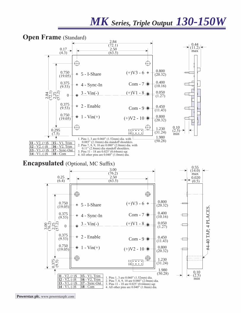
MK Series, Triple Output 130-150WOpen Frame (Standard)
0.44(11.2)max
0.10(2.5)min
1. Pins 1, 3 are 0.060” (1.52mm) dia.2. Pins 7, 8, 9, 10 are 0.080” (2.0mm) dia.3. Pins 11 - 18 are 0.025’ (0.64mm) sqr.4. All other pins are 0.040” (1.0mm) dia.
2.50(63.5)
3.00(76.2)
0.25(6.4)
2.25
(57.
2)
3.00
(76.
2)0.
375
(9.5
)
4 - Sync-In0.375(9.53)
0.375(9.53)
0.750(19.05)
0
0.55(14.0)max
#4-4
0 TA
P, 4
PLA
CES
.
0.020(0.5)
5 - I-Share0.750(19.05)
3 - Vin(-)
2 - Enable
1 - Vin(+)
Com - 9
(+)V2 - 10
0.10(2.5)min
0.800(20.32)(+)V3 - 6
0.800(20.32)
0.450(11.43)
(+)V1 - 8 0.050(1.27)
Com - 7 0.400(10.16)
1.230(31.24)11
18
11 - V2, (+)S 15 - V1, Trim12 - V2, (-)S 16 - V2, Trim13 - V1, (+)S 17 - Sync-Out14 - V1, (-)S 18 - Com
1. Pins 1, 3 are 0.060” (1.52mm) dia. with 0.085” (2.16mm) dia standoff shoulders.2. Pins 7, 8, 9, 10 are 0.080” (2.0mm) dia. with 0.11” (2.8mm) dia standoff shoulders.3. Pins 11 - 18 are 0.025’ (0.64mm) sqr.4. All other pins are 0.040” (1.0mm) dia.
2.50(63.5)
2.84(72.1)
0.17(4.3)
2.25
(57.
2)
2.84
(72.
1)
0.295(7.5)
4 - Sync-In0.375(9.53)
0.375(9.53)
0.750(19.05)
0
5 - I-Share0.750(19.05)
3 - Vin(-)
2 - Enable
1 - Vin(+)
Com - 9
(+)V2 - 10
0.800(20.32)(+)V3 - 6
0.800(20.32)
0.450(11.43)
(+)V1 - 8 0.050(1.27)
Com - 7 0.400(10.16)
1.230(31.24)1.980
(50.28)
1118
11 - V2, (+)S 15 - V1, Trim12 - V2, (-)S 16 - V2, Trim13 - V1, (+)S 17 - Sync-Out14 - V1, (-)S 18 - Com
1.980(50.28)
Encapsulated (Optional, MC Suffix)
Powerstax plc. www.powerstaxplc.com
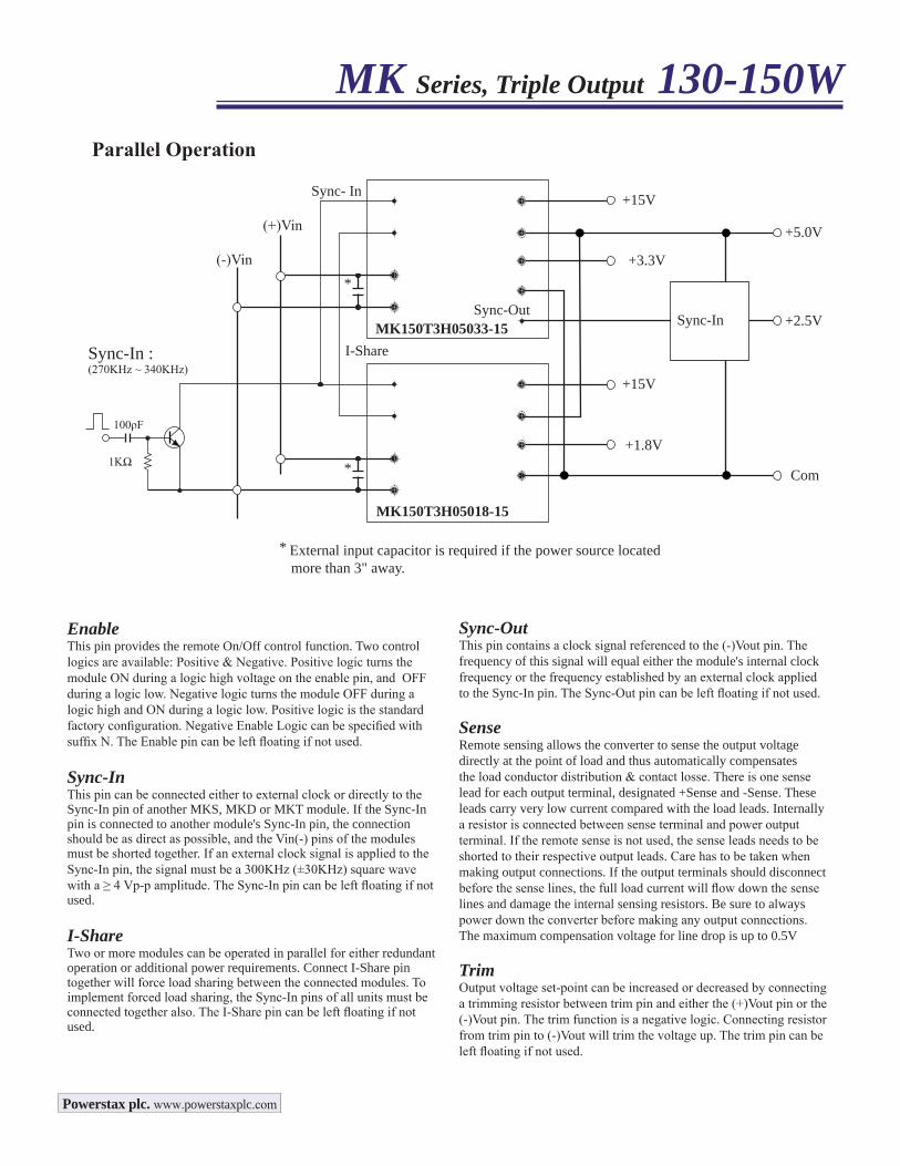
+15VSync- In
I-Share
(+)Vin
* External input capacitor is required if the power source located more than 3" away.
Parallel Operation
*
*
(-)Vin
+1.8V
+15V
+5.0V
+3.3V
Com
Sync-In : (270KHz ~ 340KHz)
100ρF
1KΩ
Sync-OutMK150T3H05033-15
MK150T3H05018-15
+2.5V
EnableThis pin provides the remote On/Off control function. Two control logics are available: Positive & Negative. Positive logic turns the module ON during a logic high voltage on the enable pin, and OFF during a logic low. Negative logic turns the module OFF during a logic high and ON during a logic low. Positive logic is the standard factory configuration. Negative Enable Logic can be specified with suffix N. The Enable pin can be left floating if not used.
Sync-InThis pin can be connected either to external clock or directly to the Sync-In pin of another MKS, MKD or MKT module. If the Sync-In pin is connected to another module's Sync-In pin, the connection should be as direct as possible, and the Vin(-) pins of the modules must be shorted together. If an external clock signal is applied to the Sync-In pin, the signal must be a 300KHz (±30KHz) square wave with a ≥ 4 Vp-p amplitude. The Sync-In pin can be left floating if not used.
I-ShareTwo or more modules can be operated in parallel for either redundant operation or additional power requirements. Connect I-Share pin together will force load sharing between the connected modules. To implement forced load sharing, the Sync-In pins of all units must be connected together also. The I-Share pin can be left floating if not used.
Sync-OutThis pin contains a clock signal referenced to the (-)Vout pin. The frequency of this signal will equal either the module's internal clock frequency or the frequency established by an external clock applied to the Sync-In pin. The Sync-Out pin can be left floating if not used.
SenseRemote sensing allows the converter to sense the output voltage directly at the point of load and thus automatically compensates the load conductor distribution & contact losse. There is one sense lead for each output terminal, designated +Sense and -Sense. These leads carry very low current compared with the load leads. Internally a resistor is connected between sense terminal and power output terminal. If the remote sense is not used, the sense leads needs to be shorted to their respective output leads. Care has to be taken when making output connections. If the output terminals should disconnect before the sense lines, the full load current will flow down the sense lines and damage the internal sensing resistors. Be sure to always power down the converter before making any output connections. The maximum compensation voltage for line drop is up to 0.5V
TrimOutput voltage set-point can be increased or decreased by connecting a trimming resistor between trim pin and either the (+)Vout pin or the (-)Vout pin. The trim function is a negative logic. Connecting resistor from trim pin to (-)Vout will trim the voltage up. The trim pin can be left floating if not used.
MK Series, Triple Output 130-150W
Sync-In
Powerstax plc. www.powerstaxplc.com