Embed Size (px)
Citation preview
ACIN TUWIEN • 1-18Author version
Automation and Control Institute TUWIEN
LaMMos - Latching Mechanism based on
Motorized-screw for Reconfigurable Robots
Draft
Luis A. Mateos∗, Markus Vincze†
Automation and Control Institute (ACIN),Vienna University of Technology (TU WIEN),Gusshausstrasse 27 - 29 / E376, A - 1040, Austria.
Abstract: Reconfigurable robots refer to a category of robots that their components (individual joints and links) can be
assembled in multiple configurations and geometries. Most of existing latching mechanisms are based on the
physical tools such as hook, cages or magnets, which limit the payload capacity. Therefore, the heavy weightrobots require a latching mechanism which can help to auto reconfigure itself without sacrificing the payload
capability. This paper presents a latching mechanism based on the flexible screw attaching principle. We use
actuators to move the robot links and joints and connect them with a motorized-screw, and disconnect them byunfastening the screw. The right-angle bracket used in our mechanism configuration helps to hold maximum
force up to 2000N. This latching mechanism based on motorized-screw has been applied to the DeWaLoP
(Developing Water Loss Prevention) in-pipe robot. It helps the robot to shrink its body to crawl into thepipe with minimum diameter, by reconfiguring the leg positions. And it helps to recover the legs positions
to original status once the robot is inside the pipe. This mechanism offers many interesting opportunities for
robotics research in terms of functionality, payload and size.
Keywords: Robotics • Reconfigurable Robots • Latching Mechanism
c© ACIN TUWIEN.
1. INTRODUCTION
In order to be better adapted to various sized targets or complex geometric requirements, it is desirable that robots
used in modern mechanical systems are geometrically reconfigurable. It means that the topological structure,
kinematic parameters or dynamic parameters of the mechanism may be adjustable during the motion process [1].
A reconfigurable robot consists of a collection of individual links and joint components that can be assembled
into multiple robot geometries. Compared to a conventional industrial robot with fixed geometry, such a system
is able to provide flexibility, enabling itself to cope with a wide spectrum of tasks through proper selection and
reconfiguration of a large inventory of functional components [2].
∗ E-mail: [email protected]† E-mail: [email protected]
1
LaMMos - Latching Mechanism based on Motorized-screw for Reconfigurable Robots
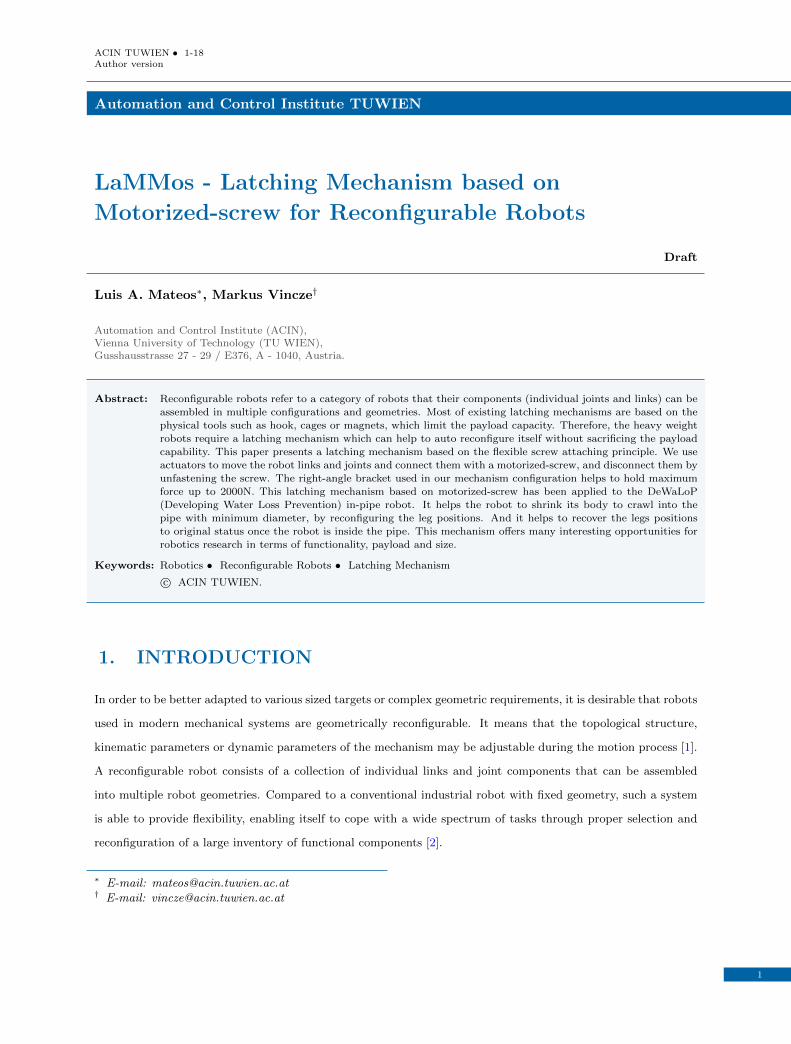
Figure 1. Aluminum profiles representing robot body where the LaMMos mechanism will be installed. 1) The T-Slot nut isinserted into the profile groove. 2) The T-Slot nut is set and trapped inside the profile groove. 3) Bracket attached bydriving the screw into the inserted T-Slot nut inside the profile. 4) Aluminum profile with a special groove. 5) T-Slotnut. 6) LaMMos bracket attached to the aluminum profile with a motorized screw to the T-Slot nut.
Commonly, these reconfigurable mechanisms join the robot links with a latching mechanism, such as hooks, cages
or magnets [3] [4] [5] [6]. In this way, the mechanism is fast to attach and flexible to connect.
However, it has the limitation of restricting the payload capacity. In following sections we will present the existing
latching mechanisms used in reconfigurable system. One can categorize them into two types, magnetic latching
and physical latching.
1.1. Magnetic latching
Miche (Modular Shape Formation by Self-Disassembly) [5] includes a connection mechanism by switchable mag-
nets, able to connect to a neighbors steel plate and can support 2kg. A similar latching mechanism is the M-TRAN
(Self-Reconfigurable Modular Robotic System) [7], which is composed of nonlinear springs, Shape Memory Alloy
(SMA) coils and magnets fixed on a moving part (connecting plate), able to lift two modules within the actual
torque limit (23kg-cm). As a result, the payload supported by these magnetics latching mechanism is relatively
low if compared to physical latching connection mechanism.
1.2. Physical latching
A. Sproewitz [8] presents a robust and heavy duty physical latching connection mechanism, which can ben seen as
a hook with clamping principles. It can be actuated with DC motors to actively connect and disconnect modular
robot units with load up to 18kg.
Similar, the Superbot [4] module consists of six connectors, one on each side of the end effectors. Any of the six
connectors of the Superbot module can connect to any connectors of another module with orientation intervals
of 90◦. The module’s drivetrain for each degree-of-freedom (DOF) includes a DC electric motor, a planetary
gearbox, and an external gearbox, resulting in a maximum of 6.38Nm torque. Given the size and weight of each
module, this amount of torque is enough for reliably lifting three neighboring modules.
2
Luis A. Mateos, Markus Vincze
JL-1 [9] is a reconfigurable multi-robots system based on parallel and cone-shaped docking mechanisms. It is
used for joining mobile robots to each other, in order to adopt a reconfigurable chain structure to cope with the
cragged landforms which are difficult to overcome for a single robot. Therefore, when two robots are linked, a
full motorized spherical joint is formed. This mechanism requires two motors on the docking side and one more
motor on the driving platform connection.
In contrast to the presented state of the art in latching mechanism, the LaMMos (Latching Mechanism based
on Motorized-screw) mechanism is able to support payloads up to 200kg and requires only one motor to make
connection.
This paper describes the LaMMos mechanism design and development. Additionally, an application of the
LaMMos mechanism on the DeWaLoP in-pipe robot is presented, in order to show how the LaMMos mechanism
improves the robot functionality.
2. Requirements for a latching mechanism in reconfigurablerobot
The aim of docking mechanism in reconfigurable robots is to attach/detach robot modules. There are a few
requirements that a latching mechanism should fulfill [10] [3] [4] [5]. However, the relevance of each single feature
differs, depending on the functionality of the robot itself. Here we list the common requirements for a docking or
connection mechanism used in self reconfiguration robots.
• Simple and fast docking procedure
• Symmetric
• Genderless
• No accidental latching
• Small size
• No power consumption in static state
• Reliable power and signal transfer
• Durable
• Stable connection
• Integration and protection of sensors
• High latch load and impact strength
• Few parts (especially moving ones)
3
LaMMos - Latching Mechanism based on Motorized-screw for Reconfigurable Robots
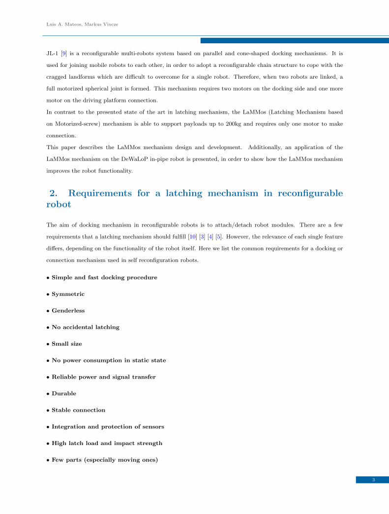
Figure 2. LaMMos mechanism. 1. Guiding system. 2. Springs. 3. Micro-geared motor. 4. Resin socket. 5. Screw. 6. Bracket7. T-Slot nut. 8. Aluminum Profile. 9. Moldable rubber inside the bracket.
• Easy maintenance
• Easy and low cost manufacturing and assembling
The integration of all required features into a single functional mechanism is challenging and should be adapted
to the purpose of the robot. All mentioned features can be implemented into LaMMos mechanism except the
genderless ability. This feature is important for modular robots. Due that modules must be able to lock/unlock
in any position. However, LaMMos is intended only for self-reconfigurable robot with predefined locking points.
3. LaMMos Mechanism Design
The LaMMos mechanisms enables robots to reconfigure its structure without loosing its payload capacity as
other common latching mechanisms do. The LaMMos mechanism adopts the flexible screw attaching principle
for connecting or disconnecting robot parts.
It can be applied to any robots having rigid materialized surface, such as aluminum profiles, in which a T-Slot
nut can be locked for further connection with brackets, as shown in figure 1.
The LaMMos mechanism mimics human operation of constructing robot links on the robot body by tightening a
screw over a nut inside the body, and deconstructing the robot links by driving the screw out of the body.
The main constituting elements of the LaMMos mechanism are divided into two main parts, the active part and
passive part. The active part includes all the elements around the bracket: geared motor, screw, moldable rubber,
couple of compressed springs, couple of guiding tubes and the bracket itself, as shown in figure 2. The passive
part is the T-slot nut inserted into the robot body, or any device inside of the robot body that provide a nut for
the screw.
4
Luis A. Mateos, Markus Vincze
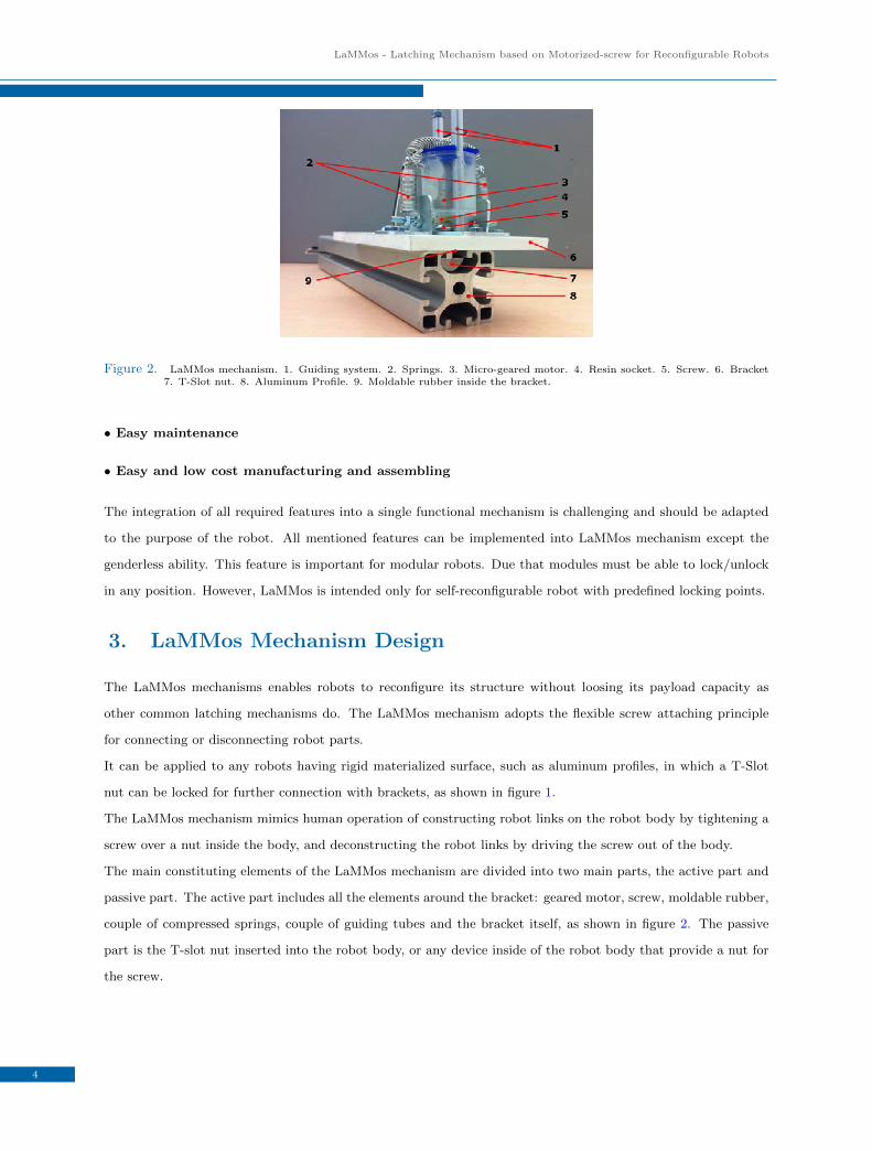
Figure 3. LaMMos driving mechanism. a) Geared motor with resin socket for hexagonal head screw. b) Geared motor withscrew integrated. c) Geared motor encapsulated with guiding tubes.
T-Slot nut
The T-Slot nut is used for securing heavy components in fastening applications. The T-Slot nuts are inserted into
the profile groove where they are secured in position by driving a screw into it. It will stay secure with holding
up maximum force up to 5000N , as shown in figure 1.
Driving mechanism - motorized-screw
The driving mechanism consists of a micro-geared motor with an integrated screw. The geared motor specifications
are in table 1.
Dimensions length = 33.2mm
width = 14mm
height = 14mm
Gear ration 298:1
Stall Torque 2884gm ∗ cm at 3V
3444gm ∗ cm at 6V
Shaft 3mm diameter D shaped
Table 1. Micro geared motor specifications.
The screw is an hexagonal head M8 with a length of 18mm. A plastic resin is modeled to joint the geared motor
with the screw. It fits the motor shaft and the hexagonal screw head, as shown in figure 3a and figure 3b.
The geared motor is encapsulated in a cylinder with radius of 27mm and length of height of 40mm. The capsule
includes two 6mm holes opposite to each other for the guiding system of the motorized-screw.
Guiding mechanism
The guiding mechanism consists of a couple of aluminum tubes attached to the bracket, with diameter of 6mm
and length of 70mm. The tubes cross the cylinder where the geared motor is encapsulated, becoming its guiding
rails, as shown in figure 3c.
In addition, the LaMMos mechanism includes a couple of compressed springs with length of 17mm and width of
5
LaMMos - Latching Mechanism based on Motorized-screw for Reconfigurable Robots
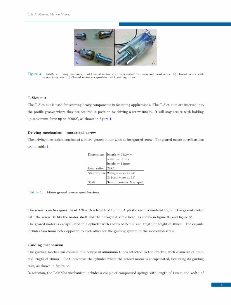
Figure 4. LaMMos mechanism in latching and unlatching status. a) Unlatching status. The screw is above the bracket. Itovercomes the force of the compressed springs by the support of the moldable rubber. b) Latching status. The screwcrosses the bracket. The moldable rubber acts as a flexible nut and initial thread for the screw.
8mm. The function of the springs is to maintain the geared motor in touch with the bracket base when it tries
to get out of it by rotating counterclockwise (unscrewing). In other words, the springs act as a pushing force for
the motorized-screw to maintain its position when the screw gets loose.
Moldable rubber
A moldable rubber is located inside the hole of the bracket. The functionality of the moldable rubber can be seen
as a flexible nut, able to guide the screw up or down from the bracket hole.
In this way, the moldable rubber acts in two different ways: housing the screw and guiding the screw.
6
Luis A. Mateos, Markus Vincze
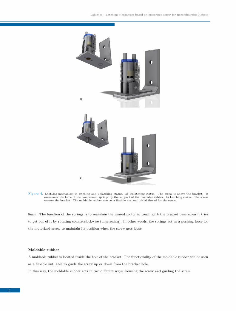
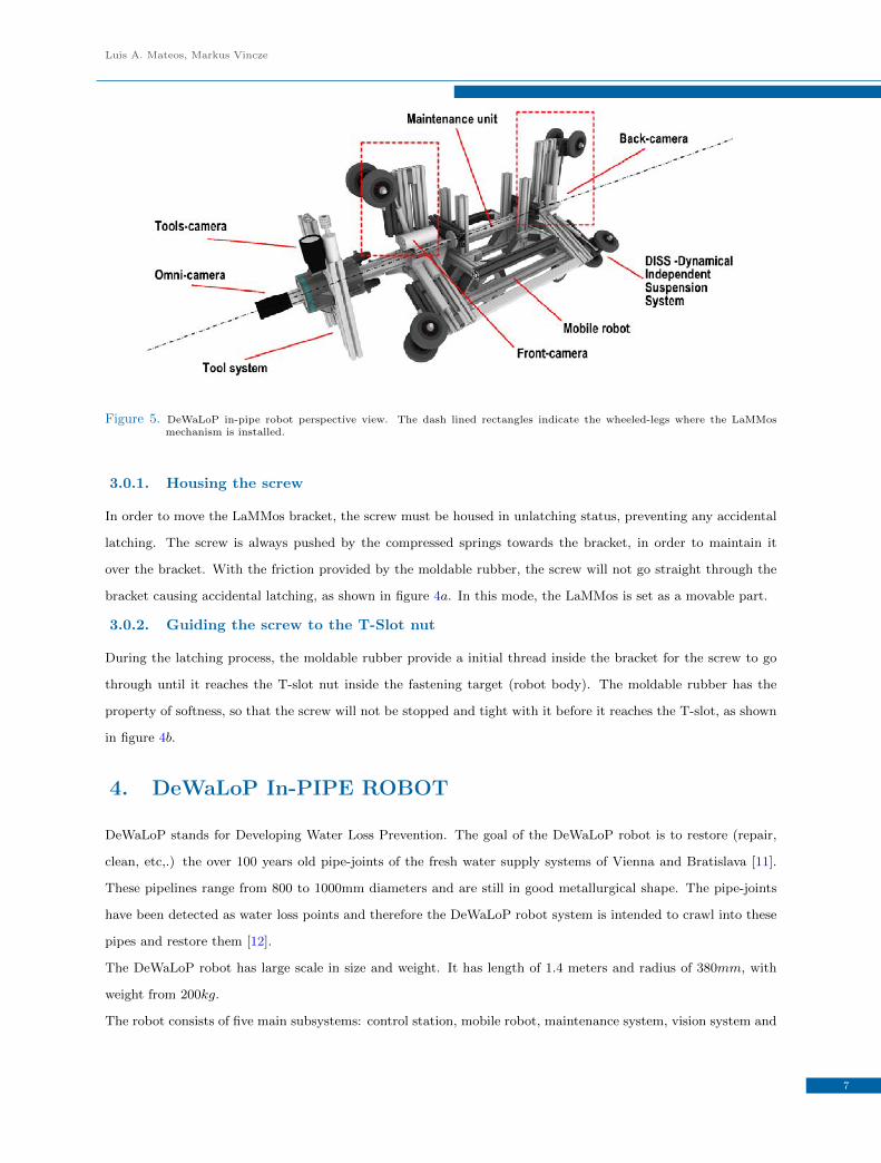
Figure 5. DeWaLoP in-pipe robot perspective view. The dash lined rectangles indicate the wheeled-legs where the LaMMosmechanism is installed.
3.0.1. Housing the screw
In order to move the LaMMos bracket, the screw must be housed in unlatching status, preventing any accidental
latching. The screw is always pushed by the compressed springs towards the bracket, in order to maintain it
over the bracket. With the friction provided by the moldable rubber, the screw will not go straight through the
bracket causing accidental latching, as shown in figure 4a. In this mode, the LaMMos is set as a movable part.
3.0.2. Guiding the screw to the T-Slot nut
During the latching process, the moldable rubber provide a initial thread inside the bracket for the screw to go
through until it reaches the T-slot nut inside the fastening target (robot body). The moldable rubber has the
property of softness, so that the screw will not be stopped and tight with it before it reaches the T-slot, as shown
in figure 4b.
4. DeWaLoP In-PIPE ROBOT
DeWaLoP stands for Developing Water Loss Prevention. The goal of the DeWaLoP robot is to restore (repair,
clean, etc,.) the over 100 years old pipe-joints of the fresh water supply systems of Vienna and Bratislava [11].
These pipelines range from 800 to 1000mm diameters and are still in good metallurgical shape. The pipe-joints
have been detected as water loss points and therefore the DeWaLoP robot system is intended to crawl into these
pipes and restore them [12].
The DeWaLoP robot has large scale in size and weight. It has length of 1.4 meters and radius of 380mm, with
weight from 200kg.
The robot consists of five main subsystems: control station, mobile robot, maintenance system, vision system and
7
LaMMos - Latching Mechanism based on Motorized-screw for Reconfigurable Robots
tool system, as shown in figure 5:
4.1. Control station
The control station monitors and controls all the components of the in-pipe robot. The controller includes a slate
computer for monitoring and displaying the video images from the robot’s Ethernet cameras. Additionally, several
8 bits micro-controllers with Ethernet capabilities are included to send and receive commands to the in-pipe robot
from the remote control joysticks and buttons [13].
4.2. Mobile robot
The mobile platform is able to move inside the pipes, carrying on board electronic and mechanical components
of the robot, such as motor drivers, power supplies, etc. It uses a differential wheel drive which enables the robot
to promptly adjust its position to remain in the middle of the pipe while moving [14].
4.3. Maintenance unit
The maintenance unit consists of a wheeled-leg structure able to extend or compress with a Dynamical Independent
Suspension System (DISS) [15]. When extending its wheeled-legs, it creates a rigid structure inside the pipe, so
the robot tools work without intense vibrations or involuntary movements from its inertia. When compressing its
wheeled-legs, the wheels become active and the maintenance unit is able to move along the pipe by the mobile
robot.
The maintenance unit structure consists of six wheeled-legs, distributed in pairs of three, on each side, separated
by an angle of 120◦, supporting the structure along the centre of the pipe, as shown in figure 5. The maintenance
unit combines a wheel-drive-system with a wall-press-system, enabling the robot to operate in pipe diameters
varying from 800mm to 1000mm [16]. Moreover, the maintenance unit together with the mobile robot form a
monolithic multi-module robot, which can be easily mounted/dismounted without the need of screws [17].
4.4. Vision system
The in-pipe robot includes four cameras, in order to navigate in the pipe, detect defects and redevelop specific
areas [18].
4.5. Tool mechanism
The tool mechanism enables the repairing of the pipe-joint in 3D cylindrical space [19] [20].
8
Luis A. Mateos, Markus Vincze
5. Evaluation of the LaMMos Mechanism in DeWaLoP in-pipeRobot
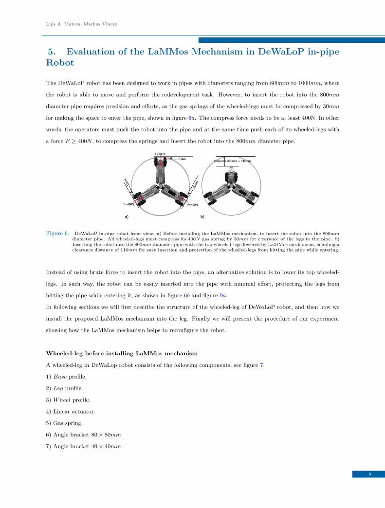
The DeWaLoP robot has been designed to work in pipes with diameters ranging from 800mm to 1000mm, where
the robot is able to move and perform the redevelopment task. However, to insert the robot into the 800mm
diameter pipe requires precision and efforts, as the gas springs of the wheeled-legs must be compressed by 30mm
for making the space to enter the pipe, shown in figure 6a. The compress force needs to be at least 400N. In other
words, the operators must push the robot into the pipe and at the same time push each of its wheeled-legs with
a force F ≥ 400N , to compress the springs and insert the robot into the 800mm diameter pipe.
Figure 6. DeWaLoP in-pipe robot front view. a) Before installing the LaMMos mechanism, to insert the robot into the 800mmdiameter pipe. All wheeled-legs must compress its 400N gas spring by 30mm for clearance of the legs to the pipe. b)Inserting the robot into the 800mm diameter pipe with the top wheeled-legs lowered by LaMMos mechanism, enabling aclearance distance of 116mm for easy insertion and protection of the wheeled-legs from hitting the pipe while entering.
Instead of using brute force to insert the robot into the pipe, an alternative solution is to lower its top wheeled-
legs. In such way, the robot can be easily inserted into the pipe with minimal effort, protecting the legs from
hitting the pipe while entering it, as shown in figure 6b and figure 9a.
In following sections we will first describe the structure of the wheeled-leg of DeWoLoP robot, and then how we
install the proposed LaMMos mechanism into the leg. Finally we will present the procedure of our experiment
showing how the LaMMos mechanism helps to reconfigure the robot.
Wheeled-leg before installing LaMMos mechanism
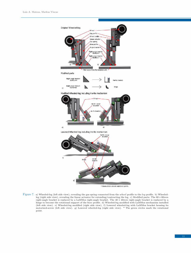
A wheeled-leg in DeWaLop robot consists of the following components, see figure 7.
1) Base profile.
2) Leg profile.
3) Wheel profile.
4) Linear actuator.
5) Gas spring.
6) Angle bracket 80 × 80mm.
7) Angle bracket 40 × 40mm.
9

LaMMos - Latching Mechanism based on Motorized-screw for Reconfigurable Robots
8) Angle bracket V .
The right-angle brackets are characterized by its high load-bearing capacity to overcome displacement, torsion
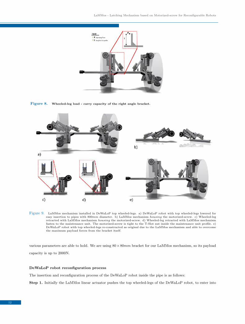
and deflection. As shown in table 2, where F refers to the operating force that the bracket can hold, and l refers
to the length of the corresponding part attached by the bracket, see figure 8.
Angle Bracket 8 40× 40mm F < 1000N ∧ F × l < 50Nm
Angle Bracket 8 80× 80mm F < 2000N ∧ F × l < 150Nm
Angle Bracket 8 160× 80mm F < 2000N ∧ F × l < 150Nm
Table 2. Load - carry capacity of the right angle bracket.
The base profile is the main support for the wheeled-leg components as it is attached with a 80 × 80mm and a
40 × 40mm right-angle brackets to the maintenance unit axis, as shown in figure 7a and 7b. To the base profile
face with the 40 × 40mm right-angle bracket, linear rails are installed to match the linear bearings from the leg
profile. In this way, the leg can be extended with a linear actuator, which is attached to the leg and to the
maintenance unit with an angle bracket V . In this configuration, the linear actuator extends the leg by pushing
and contracts the leg by pulling, as shown in figure 7b. On the leg profile, parallel and opposite to the base
profile, another linear rail with bearings is installed, attaching the wheel profile enabling it to move up or down.
Additionally, the wheel profile is supported by an extended gas spring, connecting the wheel with the leg, acting
as a suspension system, as shown in figure 7a.
Wheeled-leg after installing LaMMos mechanism
The LaMMos mechanism helps DeWaLoP robot to adjust its wheeled-legs to a lower height position before
entering the pipe and afterwards helps to recover the original vertical position once the robot is sitting inside the
pipe. The right-angle bracket 80 × 80mm is replaced by the LaMMos bracket, while the 40 × 40mm bracket is
substituted by a hinge, as shown in figure 7c.
In this configuration, the functionality of LaMMos is to attach/detach the 80 × 80mm right-angle bracket from
the base profile to the maintenance unit. The functionality of the hinge is to keep the wheeled-leg in contact with
the maintenance unit when the LaMMos is detached. In other words, the hinge is required as a joint rotational
connection between the base profile and the maintenance unit.
Additionally, for lowering the wheeled-leg, a LaMMos linear actuator is required. The linear actuator pushes the
leg to be lowered, as shown in figure 7f and 7g. And by pulling it, sets the wheeled-leg to original position which
is perpendicular to the maintenance unit. see figure 7d and 7e.
In the stage when the leg is vertical, the LaMMos mechanism acts as the replaced 80× 80mm right-angle bracket
from the base profile, as it fastens the wheeled-leg to the maintenance unit using a motorized-screw. It is able to
overcome heavy payload due to the rigid structure of LaMMos bracket.
If the leg hit obstacles when performing restoration task Table 2 shows the maximum forces F that brackets with
10
Luis A. Mateos, Markus Vincze
Figure 7. a) Wheeled-leg (left side view), revealing the gas spring connected from the wheel profile to the leg profile. b) Wheeled-leg (right side view), revealing the linear actuator for extending/contracting the leg. c) Modified parts: The 80×80mmright-angle bracket is replaced by a LaMMos right-angle bracket. The 40× 40mm right-angle bracket is replaced by ahinge to become the rotational support of the base profile. d) Wheeled-leg modified with LaMMos mechanism installed(left side view). e) Wheeled-leg modified (right side view). f) Lowered wheeled-leg with LaMMos bracket housing itsmotorized-screw (left side view). g) Lowered wheeled-leg (right side view). * The green circles mark the rotationalpoint.
11
LaMMos - Latching Mechanism based on Motorized-screw for Reconfigurable Robots
Figure 8. Wheeled-leg load - carry capacity of the right angle bracket.
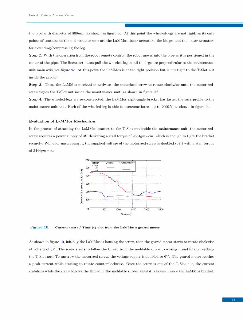
Figure 9. LaMMos mechanism installed in DeWaLoP top wheeled-legs. a) DeWaLoP robot with top wheeled-legs lowered foreasy insertion to pipes with 800mm diameter. b) LaMMos mechanism housing the motorized-screw. c) Wheeled-legretracted with LaMMos mechanism housing the motorized-screw. d) Wheeled-leg retracted with LaMMos mechanismfasten to the maintenance unit. The motorized-screw is tight to the T-Slot nut inside the maintenance unit profile. e)DeWaLoP robot with top wheeled-legs re-constructed as original due to the LaMMos mechanism and able to overcomethe maximum payload forces from the bracket itself.
various parameters are able to hold. We are using 80×80mm bracket for our LaMMos mechanism, so its payload
capacity is up to 2000N.
DeWaLoP robot reconfiguration process
The insertion and reconfiguration process of the DeWaLoP robot inside the pipe is as follows:
Step 1. Initially the LaMMos linear actuator pushes the top wheeled-legs of the DeWaLoP robot, to enter into
12
Luis A. Mateos, Markus Vincze
the pipe with diameter of 800mm, as shown in figure 9a. At this point the wheeled-legs are not rigid, as its only
points of contacts to the maintenance unit are the LaMMos linear actuators, the hinges and the linear actuators
for extending/compressing the leg.
Step 2. With the operation from the robot remote control, the robot moves into the pipe as it is positioned in the
center of the pipe. The linear actuators pull the wheeled-legs until the legs are perpendicular to the maintenance
unit main axis, see figure 9c. At this point the LaMMos is at the right position but is not tight to the T-Slot nut
inside the profile.
Step 3. Then, the LaMMos mechanism activates the motorized-screw to rotate clockwise until the motorized-
screw tights the T-Slot nut inside the maintenance unit, as shown in figure 9d.
Step 4. The wheeled-legs are re-constructed, the LaMMos right-angle bracket has fasten the base profile to the
maintenance unit axis. Each of the wheeled-leg is able to overcome forces up to 2000N , as shown in figure 9e.
Evaluation of LaMMos Mechanism
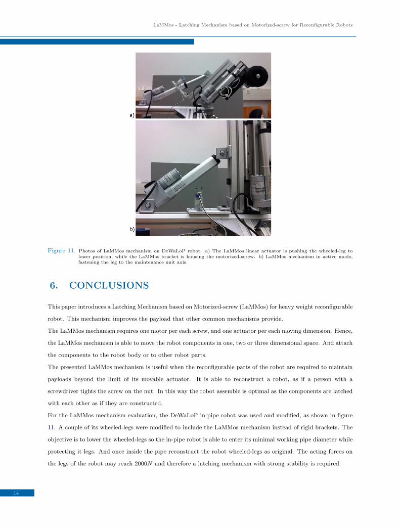
In the process of attaching the LaMMos bracket to the T-Slot nut inside the maintenance unit, the motorized-
screw requires a power supply of 3V delivering a stall torque of 2884gm∗ cm, which is enough to tight the bracket
securely. While for unscrewing it, the supplied voltage of the motorized-screw is doubled (6V ) with a stall torque
of 3444gm ∗ cm.
Figure 10. Current (mA) / Time (t) plot from the LaMMos’s geared motor.
As shown in figure 10, initially the LaMMos is housing the screw, then the geared motor starts to rotate clockwise
at voltage of 3V . The screw starts to follow the thread from the moldable rubber, crossing it and finally reaching
the T-Slot nut. To unscrew the motorized-screw, the voltage supply is doubled to 6V . The geared motor reaches
a peak current while starting to rotate counterclockwise. Once the screw is out of the T-Slot nut, the current
stabilizes while the screw follows the thread of the moldable rubber until it is housed inside the LaMMos bracket.
13
LaMMos - Latching Mechanism based on Motorized-screw for Reconfigurable Robots
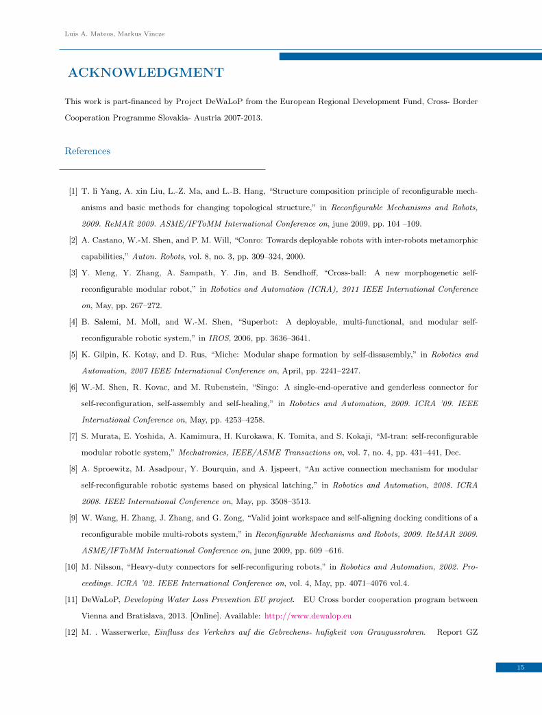
Figure 11. Photos of LaMMos mechanism on DeWaLoP robot. a) The LaMMos linear actuator is pushing the wheeled-leg tolower position, while the LaMMos bracket is housing the motorized-screw. b) LaMMos mechanism in active mode,fastening the leg to the maintenance unit axis.
6. CONCLUSIONS
This paper introduces a Latching Mechanism based on Motorized-screw (LaMMos) for heavy weight reconfigurable
robot. This mechanism improves the payload that other common mechanisms provide.
The LaMMos mechanism requires one motor per each screw, and one actuator per each moving dimension. Hence,
the LaMMos mechanism is able to move the robot components in one, two or three dimensional space. And attach
the components to the robot body or to other robot parts.
The presented LaMMos mechanism is useful when the reconfigurable parts of the robot are required to maintain
payloads beyond the limit of its movable actuator. It is able to reconstruct a robot, as if a person with a
screwdriver tights the screw on the nut. In this way the robot assemble is optimal as the components are latched
with each other as if they are constructed.
For the LaMMos mechanism evaluation, the DeWaLoP in-pipe robot was used and modified, as shown in figure
11. A couple of its wheeled-legs were modified to include the LaMMos mechanism instead of rigid brackets. The
objective is to lower the wheeled-legs so the in-pipe robot is able to enter its minimal working pipe diameter while
protecting it legs. And once inside the pipe reconstruct the robot wheeled-legs as original. The acting forces on
the legs of the robot may reach 2000N and therefore a latching mechanism with strong stability is required.
14
Luis A. Mateos, Markus Vincze
ACKNOWLEDGMENT
This work is part-financed by Project DeWaLoP from the European Regional Development Fund, Cross- Border
Cooperation Programme Slovakia- Austria 2007-2013.
References
[1] T. li Yang, A. xin Liu, L.-Z. Ma, and L.-B. Hang, “Structure composition principle of reconfigurable mech-
anisms and basic methods for changing topological structure,” in Reconfigurable Mechanisms and Robots,
2009. ReMAR 2009. ASME/IFToMM International Conference on, june 2009, pp. 104 –109.
[2] A. Castano, W.-M. Shen, and P. M. Will, “Conro: Towards deployable robots with inter-robots metamorphic
capabilities,” Auton. Robots, vol. 8, no. 3, pp. 309–324, 2000.
[3] Y. Meng, Y. Zhang, A. Sampath, Y. Jin, and B. Sendhoff, “Cross-ball: A new morphogenetic self-
reconfigurable modular robot,” in Robotics and Automation (ICRA), 2011 IEEE International Conference
on, May, pp. 267–272.
[4] B. Salemi, M. Moll, and W.-M. Shen, “Superbot: A deployable, multi-functional, and modular self-
reconfigurable robotic system,” in IROS, 2006, pp. 3636–3641.
[5] K. Gilpin, K. Kotay, and D. Rus, “Miche: Modular shape formation by self-dissasembly,” in Robotics and
Automation, 2007 IEEE International Conference on, April, pp. 2241–2247.
[6] W.-M. Shen, R. Kovac, and M. Rubenstein, “Singo: A single-end-operative and genderless connector for
self-reconfiguration, self-assembly and self-healing,” in Robotics and Automation, 2009. ICRA ’09. IEEE
International Conference on, May, pp. 4253–4258.
[7] S. Murata, E. Yoshida, A. Kamimura, H. Kurokawa, K. Tomita, and S. Kokaji, “M-tran: self-reconfigurable
modular robotic system,” Mechatronics, IEEE/ASME Transactions on, vol. 7, no. 4, pp. 431–441, Dec.
[8] A. Sproewitz, M. Asadpour, Y. Bourquin, and A. Ijspeert, “An active connection mechanism for modular
self-reconfigurable robotic systems based on physical latching,” in Robotics and Automation, 2008. ICRA
2008. IEEE International Conference on, May, pp. 3508–3513.
[9] W. Wang, H. Zhang, J. Zhang, and G. Zong, “Valid joint workspace and self-aligning docking conditions of a
reconfigurable mobile multi-robots system,” in Reconfigurable Mechanisms and Robots, 2009. ReMAR 2009.
ASME/IFToMM International Conference on, june 2009, pp. 609 –616.
[10] M. Nilsson, “Heavy-duty connectors for self-reconfiguring robots,” in Robotics and Automation, 2002. Pro-
ceedings. ICRA ’02. IEEE International Conference on, vol. 4, May, pp. 4071–4076 vol.4.
[11] DeWaLoP, Developing Water Loss Prevention EU project. EU Cross border cooperation program between
Vienna and Bratislava, 2013. [Online]. Available: http://www.dewalop.eu
[12] M. . Wasserwerke, Einfluss des Verkehrs auf die Gebrechens- hufigkeit von Graugussrohren. Report GZ
15
LaMMos - Latching Mechanism based on Motorized-screw for Reconfigurable Robots
541/09 consulting Ziviltechniker GmbH fr Verkehr, Umwelt und Infrastruktur, Wien, sterreich, 2009.
[13] L. A. Mateos, M. Sousa, and M. Vincze, “Dewalop remote control for in-pipe robot,” in , 2011 15th Interna-
tional Conference on Advanced Robotics (ICAR), june 2011, pp. 518 –523.
[14] L. A. Mateos, K. Zhou, and M. Vincze, “Towards efficient pipe maintenance: Dewalop in-pipe robot stability
controller.” in ICMA, 2012, pp. 1–6.
[15] L. A. Mateos and M. Vincze, “Dewalop robot dynamical independent suspension system,” in ICMET, 2011,
pp. 287–292.
[16] L. A. Mateos, M. Rodriguez y Dominguez, and M. Vincze, “Automatic in-pipe robot centering from 3d
controller simplification,” in IROS, 2013.
[17] L. Mateos and M. Vincze, “Dewalop-monolithic multi-module in-pipe robot system,” in ICIRA, 2011, pp.
406–415.
[18] L. A. Mateos and M. Vincze, “Dewalop - robot vision system,” in CET, 2011, pp. 65–68.
[19] L. A. Mateos, A. Rakos, and M. Vincze, “Dewalop in-pipe redevelopment system design,” in ARW, 2012,
pp. 101–106.
[20] L. A. Mateos and M. Vincze, “In-pipe cleaning mechanical system for dewalop -developing water loss pre-
vention,” in ARW, 2013, pp. 37–42.
16