Embed Size (px)
Citation preview
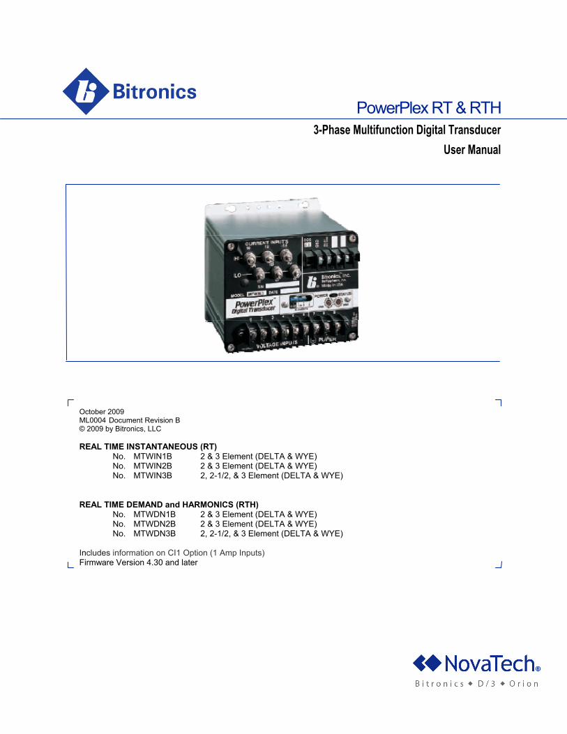
PowerPlex RT & RTH 3-Phase Multifunction Digital Transducer
User Manual
October 2009 ML0004 Document Revision B © 2009 by Bitronics, LLC REAL TIME INSTANTANEOUS (RT)
No. MTWIN1B 2 & 3 Element (DELTA & WYE) No. MTWIN2B 2 & 3 Element (DELTA & WYE) No. MTWIN3B 2, 2-1/2, & 3 Element (DELTA & WYE)
REAL TIME DEMAND and HARMONICS (RTH)
No. MTWDN1B 2 & 3 Element (DELTA & WYE) No. MTWDN2B 2 & 3 Element (DELTA & WYE) No. MTWDN3B 2, 2-1/2, & 3 Element (DELTA & WYE)
Includes information on CI1 Option (1 Amp Inputs) Firmware Version 4.30 and later

ML0004 November 2009 Copyright 2009 Bitronics LLC i
TABLE OF CONTENTS
TABLE OF CONTENTS.............................................................................. i FIRMWARE REVISION LIST .................................................................... iii CERTIFICATION ....................................................................................... iv COPYRIGHT ............................................................................................. iv INSTALLATION AND MAINTENANCE ...................................................... iv WARRANTY AND ASSISTANCE .............................................................. iv 1.0 DESCRIPTION .................................................................................... 1 1.1 Introduction .......................................................................................... 1 1.2 Features .............................................................................................. 1 1.3 Specifications ...................................................................................... 2 2.0 PRINCIPLES OF OPERATION ........................................................... 4 2.1 Construction ........................................................................................ 4
2.1.1 Output Connector Board .............................................................. 4 2.1.2 Current and Potential Transformer
Board (CT/PT Board) ...................................... 4 2.1.3 Power Supply Board (PS Board) .................................................. 5
2.1.3a Universal Power Supply ........................................................ 5 2.1.3b AC Power Supply .................................................................. 5
2.1.4 Main Processor Board (MP Board) .............................................. 5 2.1.4a Analog Section ...................................................................... 6
2.1.4b Digital Section ....................................................................... 6 2.1.5 Network Interface Board .............................................................. 6
2.2 Instantaneous Measurement Principles ............................................... 6
2.2.1 Voltage / Current .......................................................................... 7 2.2.2 Neutral Current (Residual Current) .............................................. 7 2.2.3 Watts / VARs ............................................................................... 7 2.2.4 Energy ......................................................................................... 7 2.2.5 Frequency .................................................................................... 8 2.2.6 Volt-Amperes ............................................................................... 8 2.2.7 Power Factor................................................................................ 8
2.3 Demand Measurements (RTH) ............................................................. 8
2.3.1 Ampere Demands ..................................................................... 9 2.3.2 Neutral Current Demand ........................................................... 9 2.3.3 Volt Demands ......................................................................... 10 2.3.4 Watt / VAR / VA Demands ...................................................... 10
2.4 Harmonic Measurements (RTH) ......................................................... 11
2.4.1 Voltage Distortion (THD) ......................................................... 11 2.4.2 Current Distortion (TDD) ......................................................... 11
ML0004 November 2009 Copyright 2009 Bitronics LLC ii
TABLE OF CONTENTS Continued 2.4.3 Fundamental Current .............................................................. 12 2.4.4 Fundamental Voltage .............................................................. 12 2.4.5 Fundamental Neutral Current ................................................. 13 2.4.6 K-Factor .................................................................................. 13 2.4.7 Displacement Power Factor .................................................... 13 2.4.8 Fundamental Neutral Demand ................................................ 14 2.4.9 Current TDD Demand ............................................................. 14 2.4.10 Voltage THD Demand ........................................................... 15
2.5 Measurement Resets ......................................................................... 15
2.5.1 Energy Reset .............................................................................. 15 2.5.2 Demand Resets (RTH) ............................................................... 15
3.0 INSTALLATION ................................................................................ 17 3.1 Initial Inspection ................................................................................. 17 3.2 Grounding .......................................................................................... 17 3.3 Power and Input Signal Connections ................................................. 17
3.3.1 Power Supply Connections ........................................................ 17 3.3.1a Universal Power Supply (-VD10) ................................... 17 3.3.1b AC Supply (-V3, -VA5, -VA9) ......................................... 17
3.3.2 Current Input (CT) Connections .................................................. 18 3.3.3 Voltage Input (PT) Connections .................................................. 18
3.4 Overcurrent Protection ....................................................................... 18 3.5 Mains Disconnect ............................................................................... 18 3.6 Instrument Mounting ........................................................................... 18 3.7 Surge Protection ................................................................................. 18 3.8 Setting Instrument Address ................................................................ 19 3.9 Setting Element Select Switches ........................................................ 19 4.0 FIELD ADJUSTMENTS ..................................................................... 19 4.1 Rescaling ............................................................................................ 19 4.2 Calibration .......................................................................................... 20 4.3 Self Test Modes .................................................................................. 20 4.4 Cleaning ............................................................................................. 21 5.0 QUESTIONS AND ANSWERS .......................................................... 21 6.0 CONNECTION DIAGRAMS ............................................................... 22
ML0004 November 2009 Copyright 2009 Bitronics LLC iii
FIRMWARE REVISIONS
PowerPlex Firmware Description
3.20 Original PowerPlex Transducer Firmware.
3.30 Added writable Ratios, VA's, Power Factor.
3.50 Maintenance revision. 3.60 Corrected error of 3-Phase VAs and PF in
Delta connected units. Delta VA calculation now Geometric VAs.
3.70 Corrected Energy roll-over error. All four
energy values now roll-over at 99,999,999 to 0. Prior versions incorrectly roll-over at 16,777,215 to 65,536.
3.80 Maintenance revision.
4.10 PowerPlex RTH Meter Firmware. Added
Harmonic measurements, decreased response time from 600ms to 150ms.
4.20 Added Tag Register, Configuration Registers,
Network Screen setup. Changed to FFT fundamental quantities for determination of PF and VARs sign.
4.30 Added RT (MTWIN_B) support.
4.50 Fixed energy BCD conversion bug.

ML0004 November 2009 Copyright 2009 Bitronics LLC
iv
CERTIFICATION Bitronics LLC certifies that the calibration of its products are based on measurements using equipment whose calibration is traceable to the United States National Institute of Standards Technology (NIST). COPYRIGHT This Option Manual is copyrighted and all rights are reserved. The distribution and sale of this manual are intended for the use of the original purchaser or his agents. This document may not, in whole or part, be copied, photocopied, reproduced, translated or reduced to any electronic medium or machine-readable form without prior consent of Bitronics LLC, except for use by the original purchaser. INSTALLATION AND MAINTENANCE Bitronics' products are designed for ease of installation and maintenance. As with any product of this nature, however, such installation and maintenance can present electrical hazards and should only be performed by properly trained and qualified personnel. If the equipment is used in a manner not specified by Bitronics, the protection provided by the equipment may be impaired. WARRANTY AND ASSISTANCE This product is warranted against defects in materials and workmanship for a period of thirty-six (36) months from the date of their original shipment from the factory. Products repaired at the factory are likewise warranted for eighteen (18) months from the date the repaired product is shipped, or for the remainder of the product's original warranty, whichever is greater. Obligation under this warranty is limited to repairing or replacing, at our designated facility, any part or parts that our examination shows to be defective. Warranties only apply to products subject to normal use and service. There are no warranties, obligations, liabilities for consequential damages, or other liabilities on the part of Bitronics LLC except this warranty covering the repair of defective materials. The warranties of merchantability and fitness for a particular purpose are expressly excluded. For assistance, contact Bitronics LLC at: Telephone: 610.997.5100 Fax: 610.997.5450 Email: [email protected] Website: www.novatechweb.com/bitronics
Shipping: 261 Brodhead Road Bethlehem, PA 18017-8698 USA
ML0004 November 2009 Copyright 2009 Bitronics LLC
2
1.0 DESCRIPTION 1.1 Introduction The Bitronics Three Phase PowerPlex Digital Transducer is an all digital re-invention of the traditional analog transducer concept. Unlike its analog predecessors, the PowerPlex can communicate information about many quantities over just one output, vastly reducing the number of transducers and wire connections needed. These quantities include current and voltage, as well as real and reactive power, power factor, energy, and frequency; all essential quantities which must be measured accurately in order to optimize the control and delivery of electric power. The use of "State-of the Art" microprocessor technology assures digital accuracy and repeatability across a wide range of input signal levels. The PowerPlex Digital Transducer is a rugged electronic instrument designed for utility and industrial applications requiring reliable, precise measurements of three-phase power systems. PowerPlex RT Transducers (MTWIN_B) provide a wide range of Real Time measurements, with RTH (MTWDN_B) units providing additional Real Time Harmonic and Demand measurements. True RMS measurements are standard, and accuracy is maintained even with the presence of harmonics above the 31st harmonic on current and voltage waveforms. The standard power supply for the PowerPlex allows it to be used on a variety of common AC or DC voltages, and the PowerPlex also provides the user with the capability to connect directly with a variety of digital communications protocols. This capability allows users to seamlessly integrate Bitronics PowerPlex instruments into an existing or planned SCADA or PLC system. 1.2 Features
* Fast Fourier Transforms (FFTs) for Harmonic measurements are performed by the instrument. Provides continuous harmonic information for operations without time delay from off-line analysis of waveform data. (RTH only)
* % Total Demand Distortion on Current with user-defined denominator. This
provides more meaningful harmonic information for various operating conditions. (RTH only)
* Displacement Power Factor allows users to more accurately size and control
power factor correction. True Power Factor allows users to measure the effects of harmonics on their system utilization. (RTH only)
* High Speed calculations provide a speed improvement for tighter automated
control applications.
* All measured quantities available over the digital communications channel to SCADA or PLC systems.
* Non-volatile memory backup of CT/PT settings. No batteries are needed.
* On board diagnostics continually monitor instrument performance.
Diagnostic codes available over network.
ML0004 November 2009 Copyright 2009 Bitronics LLC
3
* Separate communications microprocessor to off-load the main processor
simplifies development of additional protocols.
* Universal power supply works on ac or dc service; 24, 48, 125 or 250V dc station batteries or 115V ac service. AC-only power supplies allow +/- 20% line voltage variation. Available for 115, 230, or 480V ac systems.
* UL listed (UL-3111-1), CSA listed (CSA C22.2 1010.1-92) IEC (1010-1), and
IEEE Surge Withstand Capability (C37.90.1-1989).
* True RMS measurements are standard.
* Rugged metal housing fits into existing analog transducer installations.
* Watchdog timer maximizes system reliability.
* Front panel switch selects 2 (DELTA), 2 ½ (WYE, MTWDN3 only), or 3 Element (WYE) Modes.
1.3 Specifications Input Signals
Amperes: 0 to 5*A ac (0.25*A ac minimum for PF and Harmonics), with continuous overload to 10*A ac (15*A ac for Neutral Current), 400Aac for 2 seconds. 2500V ac isolation, minimum.
Volts: MTW_N3B: 120V ac nom., Range 0 to 150Vac, three phase. 2500V ac min
isolation. MTW_N1B: 120VL-N/208(240)VL-L nom., Range 0 to 300V ac (300 VL-G Maximum),
5000V ac min isolation, 2:1 Integral PT. MTW_N2B: 277VL-N/480VL-L nom., Range 0 to 520V ac (300 VL-G Maximum),
5000V ac min isolation, 4:1 Integral PT. Minimum input for PF, Harmonics or Frequency=16% of Range.
Signal Burden
Amperes: 4mV ac at 5Aac input ( 0.02 VA ) Volts: MTW_N3B: <1 mA ac at 120V ac input ( 0.1 VA ) MTW_N1B: <0.6mA ac at 240V ac input ( 0.15 VA ) MTW_N2B: <1.2mA ac at 480V ac input ( 0.6 VA )
Accuracy: 0.25% Class (ANSI Std 460-1988)
ML0004 November 2009 Copyright 2009 Bitronics LLC
4
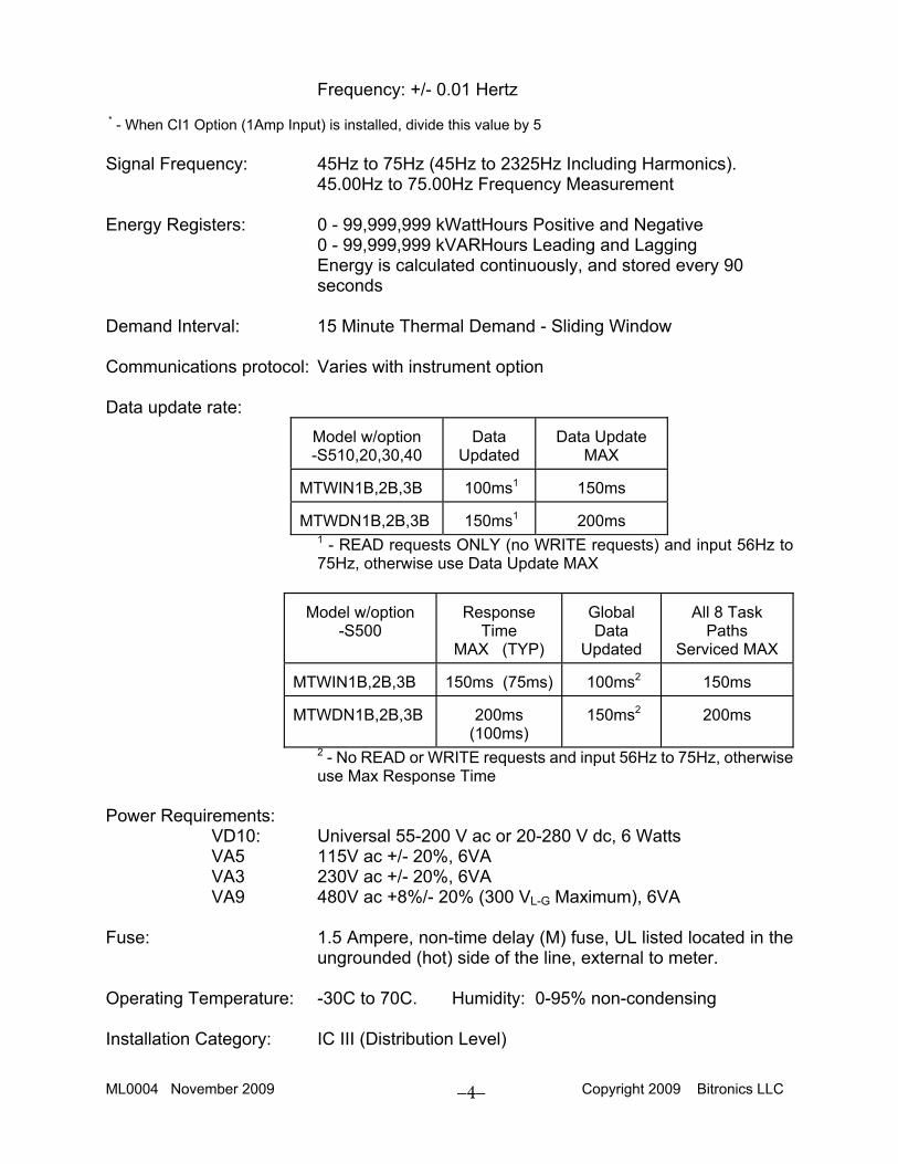
Frequency: +/- 0.01 Hertz * - When CI1 Option (1Amp Input) is installed, divide this value by 5 Signal Frequency: 45Hz to 75Hz (45Hz to 2325Hz Including Harmonics).
45.00Hz to 75.00Hz Frequency Measurement Energy Registers: 0 - 99,999,999 kWattHours Positive and Negative
0 - 99,999,999 kVARHours Leading and Lagging Energy is calculated continuously, and stored every 90 seconds
Demand Interval: 15 Minute Thermal Demand - Sliding Window Communications protocol: Varies with instrument option Data update rate:
Model w/option -S510,20,30,40
Data Updated
Data Update MAX
MTWIN1B,2B,3B 100ms1 150ms MTWDN1B,2B,3B 150ms1 200ms
1 - READ requests ONLY (no WRITE requests) and input 56Hz to 75Hz, otherwise use Data Update MAX
Model w/option -S500
Response Time
MAX (TYP)
Global Data
Updated
All 8 Task
Paths Serviced MAX
MTWIN1B,2B,3B 150ms (75ms) 100ms2
150ms
MTWDN1B,2B,3B 200ms
(100ms) 150ms2
200ms
2 - No READ or WRITE requests and input 56Hz to 75Hz, otherwise use Max Response Time
Power Requirements:
VD10: Universal 55-200 V ac or 20-280 V dc, 6 Watts VA5 115V ac +/- 20%, 6VA VA3 230V ac +/- 20%, 6VA VA9 480V ac +8%/- 20% (300 VL-G Maximum), 6VA
Fuse: 1.5 Ampere, non-time delay (M) fuse, UL listed located in the
ungrounded (hot) side of the line, external to meter. Operating Temperature: -30C to 70C. Humidity: 0-95% non-condensing Installation Category: IC III (Distribution Level)

ML0004 November 2009 Copyright 2009 Bitronics LLC
5
Pollution Degree: 2 Weight: 3.5 pounds ( 1.60 kilograms ) Size: 5.25"H x 5.60"W x 5.63"D
ML0004 November 2009 Copyright 2009 Bitronics LLC
6
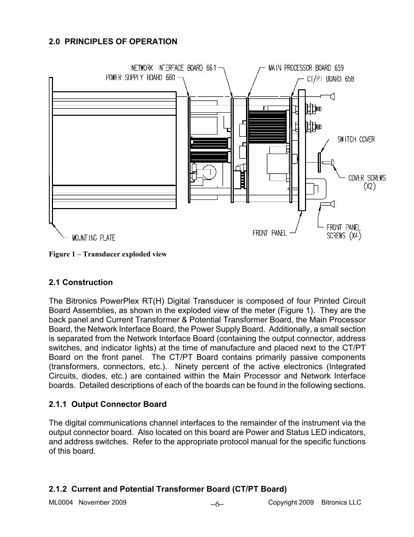
2.0 PRINCIPLES OF OPERATION
Figure 1 – Transducer exploded view 2.1 Construction The Bitronics PowerPlex RT(H) Digital Transducer is composed of four Printed Circuit Board Assemblies, as shown in the exploded view of the meter (Figure 1). They are the back panel and Current Transformer & Potential Transformer Board, the Main Processor Board, the Network Interface Board, the Power Supply Board. Additionally, a small section is separated from the Network Interface Board (containing the output connector, address switches, and indicator lights) at the time of manufacture and placed next to the CT/PT Board on the front panel. The CT/PT Board contains primarily passive components (transformers, connectors, etc.). Ninety percent of the active electronics (Integrated Circuits, diodes, etc.) are contained within the Main Processor and Network Interface boards. Detailed descriptions of each of the boards can be found in the following sections. 2.1.1 Output Connector Board The digital communications channel interfaces to the remainder of the instrument via the output connector board. Also located on this board are Power and Status LED indicators, and address switches. Refer to the appropriate protocol manual for the specific functions of this board. 2.1.2 Current and Potential Transformer Board (CT/PT Board)
ML0004 November 2009 Copyright 2009 Bitronics LLC
7
The current and potential transformer (CT/PT) board contains secondary transformers which provide electrical isolation for each of the signal input channels, as well as the switches to select 2 (DELTA), 2½ (WYE, MTW_N3 only), or 3 Element (WYE) operation. Current from the current terminals flows though a silver-soldered shunt of negligible resistance to assure that the user's external CT circuit can never open-circuit, even under extreme fault conditions. Potential voltages are carried through #8 screws on high barrier terminal strips directly to the CT/PT board to guarantee reliable connections to the high-impedance secondary transformer circuits. The use of transformers on all input leads provides excellent isolation between the inputs and any output. The PowerPlex Digital Transducer uses a six wire voltage input, which along with Element Select Switch allows great flexibility in connection. Bitronics PowerPlex instruments provide for complete interchangeability of Main Processor and CT/PT boards. Compensation for normal variations in input circuits is achieved by storing calibration constants in a non-volatile memory (EEPROM) which resides on the CT/PT board. These constants are factory-programmed to provide identical signal gain (attenuation) in each of the six isolated signal input paths. The CT and PT settings for scaling the transmitted values to the user's CTs and PTs are also stored in this EEPROM. Checksums are incorporated into the EEPROM which are read periodically by the microcontroller to check the integrity of the calibration constants and the CT and PT setting (See section 4.1). The Energy Registers are also stored in this EEPROM (See section 2.2.4). Checksums are incorporated into the EEPROM which are read periodically by the microcontroller to check the integrity of the energy registers. 2.1.3 Power Supply Board (PS Board) 2.1.3a Universal Power Supply The Universal power supply is a high-efficiency, high-frequency switching power supply with integrated over-current protection. Power from the input terminals is conducted to a full-wave bridge rectifier and capacitor to convert AC power inputs to DC. DC power inputs are unaffected by the bridge rectifier. Input polarities are marked for reference only. The DC voltage across the filter capacitor is alternately connected and disconnected to the isolation/power transformer at a rate of about 60kHz, by a pulse-width controller. A separate feedback winding on the power transformer provides a signal which is used by the controller to vary the time that the transformer is connected to the power source. This allows the supply to provide a relatively constant output voltage over a wide range of input voltages and output loads. The output of the switching supply is then post regulated by low-drop linear regulators to provide precise supply voltage control under all conditions. Two separate, isolated outputs are created; one for the output port, and one for the rest of the instrument. 2.1.3b AC Power Supply
ML0004 November 2009 Copyright 2009 Bitronics LLC
8
The AC power supply circuit is a conservative, conventional design. Low drop rectifiers and a low drop-out solid state regulator minimize internal power dissipation. Filter capacitors are operated at a fraction of their voltage and temperature ratings, and should provide years of trouble-free service under extreme environmental conditions. Two separate, isolated outputs are created; one for the output port, and one for the rest of the instrument. 2.1.4 Main Processor Board (MP Board) The MP Board is divided into two parts, the Analog and Digital processor sections: 2.1.4a Main Processor Analog Processing Section The first function of Analog Processing section is to sum the three low level AC signals from the three CTs to form the Neutral Current Signal (2 ½ and 3 Element Modes only). Similarly, the phase A and C voltage signals are summed to form the phase B input voltage for use in 2 ½ Element Mode. These functions are performed by precision analog summing circuits. The second function of Analog Processing section is to sample and digitize the low level AC signals provided by the CT/PT board, and to provide a digital number to the microcontroller section for further processing. Calibration constants stored in both the CT/PT EEPROM and the EEPROM located on this board provide drift-free calibration, and complete interchangeability of Main Processor boards. Checksums are incorporated into both EEPROMs which are read periodically by the microcontroller to check the integrity of the calibration constants and the CT and PT setting ( See section 4.1 ). A "Master Gain" trimpot is also located on the MP board to provide the user with fine tuning capability if it is necessary to match other devices on the power system. 2.1.4b Main Processor Digital Microcontroller Section The host microcontroller section consists of an Intel 87C251SB16 microcontroller (MCU), address latch, EPROM memory, SRAM memory and a watchdog timer. All the data acquisition and signal processing are controlled by the microcontroller. Communications to other boards is accomplished via a serial data link consisting of three lines common to all the other devices (ADC, 2 EEPROMs). Individual select lines for each individual device, allow the MCU to communicate with one device at a time. The watchdog timer prevents the MCU from "locking up" in the event of a transient or other type of interference. The watchdog timer also provides a reset on power-up or when resuming from a brownout (low supply). In the unlikely event of a microcontroller failure, the watchdog circuit will continuously attempt to restart the processor. A DUAL-PORT RAM is also located on the Host MCU board. The purpose of the DUAL-PORT RAM is to provide a communications channel between the Host MCU and the microprocessor on the Network Processor Board. The two processors pass "messages" through this RAM in order to service specified communications protocol transactions. 2.1.5 Network Interface Board The Network Interface Board contains the intelligent interface between the host MCU board
ML0004 November 2009 Copyright 2009 Bitronics LLC
9
and the specified communications protocol. The board content varies with the specific protocol chosen and is fully described in the appropriate protocol option manual. 2.2 Instantaneous Measurement Principles All the quantities measured by the PowerPlex RTH instrument utilize digital signal processing (DSP). This technique allows the instrument to measure a large number of quantities with a small amount of hardware. It also allows field upgrades, since the signal processing algorithms are in an EPROM, and can be simply changed to provide new features. The following section will give a brief overview of the measurement principles. 2.2.1 Voltage / Current Signal processing begins with the low level AC signal supplied from the CT/PT board which is about 1V ac RMS for a full scale input signal. Pure sine wave inputs or complex, distorted, periodic waveforms are handled equally well - a major advantage when computing WATTs and VARs as well as true RMS currents and voltages. This design frees the user from concern about errors which will otherwise occur during the measurement of distorted waveforms with non-true RMS instruments. Voltage of a given phase is sampled first, followed by the current of the same phase. Phases A, B and C are sampled in succession, providing the MCU with instantaneous measurements of all voltage and current inputs. Samples are accumulated for three AC cycles, at which time the MCU calculates the Volts and Amps for each phase. Any Zero Offset or drift is compensated for every calculation cycle. When the PowerPlex is in 2 ½ Element mode (MTW_N3B only, Sec. 2.1.4a), an artificial phase B voltage is created by a vector sum of the phase A and phase C voltages. A summing amplifier, located on the Main Processor Board, is used to create the phase B signal. This artificial phase B signal is used in all relevant calculations. 2.2.2 Neutral Current (Residual Current) for WYE Connections In the WYE mode, the analog voltage signals from the three phase currents are summed on the Main Processor Board to form a new analog input that represents the Neutral Current (Residual Current). This signal is sampled at the same time as the other six signals (Phase Currents and Voltages). Samples are accumulated for three AC cycles, at which time the RMS value of the Neutral Current (Residual Current) is calculated by the MCU. 2.2.3 Watts / VARs Instantaneous Watt samples are accumulated for three AC cycles, at which time the MCU calculates the WATTs and VARs for each phase. The VARS quantity for each phase is derived from a power triangle calculation where the WATTS and VAs are known. This technique provides a "true" measure of VARs even with distorted waveforms. Zero offset is also adjusted for each signal channel every 100 milliseconds (150msec for MTWDN_B) by the MCU. These per-phase quantities are then summed to form the total three phase WATTS and VARS. Once the WATTS and VARS have been calculated, the MCU scales
ML0004 November 2009 Copyright 2009 Bitronics LLC
10
the values by the external PT and CT ratios which have been selected by the user. 2.2.4 Energy The WATT and VAR values are calculated every 100 milliseconds (150msec for MTWDN_B). These values are then multiplied by a time factor in order to generate WATThours and VARhours. The signs of the WATThour and VARhour values are then checked, and the values are then added to the appropriate registers (Positive/Negative WATThours, Lead/lag VARhours). These registers are updated every 100 milliseconds (150msec for MTWDN_B). In order to retain the energy values during a power failure, the registers must be stored in the EEPROM on the CT/PT board of the unit. The EEPROM has a limited number of write cycles, so the energy registers are only written every 90 seconds. At this rate, the EEPROM will last in excess of 15 years at rated conditions. Checksums are incorporated into the EEPROM which are read periodically by the microcontroller to check the integrity of the energy registers. The registers are in PRIMARY kilowatt-hours and kiloVAR-hours, and the CT and PT ratio are used to calculate the primary units. The Energy registers count to a maximum of 99,999,999 units before rolling over to zero. It is the responsibility of the user to ensure that these values are read often enough to detect every rollover. All the Energy registers can be RESET to 0000 through the communications interface. Refer to the appropriate protocol option manual for the protocol specific RESET command. The energy values will be reset within 0.6 seconds, however it takes the meter 4 seconds to clear the energy data stored in the EEPROM. The USER must ensure that the power is not interrupted to the meter for this 4 second period after the energy is RESET or the reset may NOT occur. 2.2.5 Frequency The Frequency measurement is generated by timing zero-crossings of the input Line Voltages or Line Currents over a period of 100msec (150msec for MTWDN_B). The microprocessor uses Phase A voltage (A-B in Delta) if available, for the frequency measurement. If Phase A is not available, the processor will switch to Phase B (B-C) and then to Phase C (C-A). If none of the voltages are available, the processor will attempt to use the Phase A current, then the Phase B current, then the Phase C current. The zero-crossings are determined from the analog samples directly. The samples are first sent through a smoother, which acts as a lowpass filter. Knowing the number of zero-crossings and the time between them, the frequency can be calculated. The input voltage must be greater than 16% of the input range for the frequency function to determine a value. If the input voltage is too low, or the frequency is below 45Hz, the instrument will return a value of 0Hz. If the frequency is above 75Hz, the instrument will return a value of 99.99Hz. 2.2.6 Volt-Amperes The per-phase VA measurement is calculated from the product of the per-phase Amp and Volts values. In WYE mode, the three-phase VA measurement is the sum of the per-phase VA values (Arithmetic VAs). In 2-element (DELTA) mode, the three-phase VA measurement is calculated from a power triangle VA2 = W2 + VAR2 (Geometric VAs).
ML0004 November 2009 Copyright 2009 Bitronics LLC
11
2.2.7 Power Factor The per-phase Power Factor measurement is calculated using the "Power Triangle", or the per-phase WATTS divided by the per-phase VAs. The three-phase PF is similar, but uses the three-phase WATTS and VAs instead. The Power Factor measurements require a minimum current of approximate 0.25A ac (0.05Aac with CI1 option) and minimum voltage of approximately 16% of Range to determine an accurate answer. If the input signals are below these values, the instrument will indicate an under-range by returning an out of range value via the network. 2.3 Demand Measurements (RTH Only) The traditional thermal demand meter displays a value which represents the logarithmic response of a heating element in the instrument driven by the applied signal. The most positive value since the last instrument reset is known as the maximum demand (or peak demand) and the lowest value since the last instrument reset is known as the minimum demand. Since thermal demand is a heating and cooling phenomenon, the demand value has a response time T, defined as the time for the demand function to change 90% of the difference between the applied signal and the initial demand value. For utility applications, the traditional value of T is 15 minutes, and this is the value used in the Bitronics PowerPlex RTH (MTWDN_B) Digital Transducer. The Bitronics PowerPlex RTH (MTWDN_B) Digital Transducer generates a demand value using modern microprocessor technology in place of heating and cooling circuits, it is therefore much more accurate and repeatable over a wide range of input values. In operation, the Bitronics PowerPlex RTH Digital Transducer continuously samples the three-phase Amperes, three-phase Volts, Neutral Current (2½ or 3 Element Mode), Total Watts, Total VARs, and Vas, and digitally integrates the samples with a time constant T to obtain the demand value. Bitronics PowerPlex RTH Digital Transducers also calculate Fundamental Neutral Current Demand (2½ or 3 Element Mode), three-phase Voltage %THD Demand, and three-phase Current %TDD Demand (See Section 2.4). The calculated demand value is continuously checked against the previous maximum and minimum demand values and is displayed on the appropriate display. Present demand values are not displayed but are available via the network interface. This process continues indefinitely or until the demand is reset or the meter is reset (power cycled on meter). The demand reset and power-up algorithms are different for each measurement. These routines are further described as follows (Fundamental Neutral Current Demand, Voltage %THD Demand, and Current %TDD are described in the Harmonic Section). NOTE: Changing PT or CT ratios resets all demand measurements (Presents, Maximums
and Minimums) to zero. 2.3.1 Ampere Demands Present Ampere Demands are calculated via the sampled data used to calculate the per phase Amperes. The Present Ampere Demands and Maximum Ampere Demands are updated approximately every 150 milliseconds. The Present Ampere Demands are not

ML0004 November 2009 Copyright 2009 Bitronics LLC
12
displayed but are available via the network interface. Maximum Ampere Demands are displayed and are also available via the interface. Upon power-up, all per-phase Present Ampere Demands are reset to zero. Maximum Ampere Demands are initialized to the maximum values recalled from non-volatile memory (EEPROM). Upon DEMAND RESET, all per-phase Present and Maximum Ampere demands are set to zero. Ampere Demands may be reset via the front panel button when the global demand reset screen is enabled or via the network. When Ampere Demands are reset via the network, Neutral Current Demand and Fundamental Neutral Current Demands are also reset (2½ or 3 Element Mode). 2.3.2 Neutral Current Demands Neutral Current Demands are only available in 2½ or 3 Element Modes. Present Neutral Current Demands are calculated via the sampled data used to calculate the Neutral Current. The Present Neutral Current Demand and Maximum Neutral Current Demand are updated approximately every 150 milliseconds. The Present Neutral Current Demand is not displayed but is available via the network interface. Maximum Neutral Current Demand is displayed and is also available via the interface. Upon power-up, the Present Neutral Current Demands is reset to zero. The Maximum Neutral Current Demand is initialized to the maximum value recalled from non-volatile memory (EEPROM). Upon DEMAND RESET all the Present and Maximum Neutral Current Demands are set to zero. The Neutral Current Demands may be reset via the front panel button when the global demand reset screen is enabled or via the network. When the Neutral Current Demands are reset via the network, all per-phase Ampere Demands and Fundamental Neutral Current Demand are also reset. 2.3.3 Volt Demands Present Volt Demands are calculated via the sampled data used to calculate the per phase Volts. The Present Volt Demands, Maximum Volt Demands, and Minimum Volt Demands are updated approximately every 150 milliseconds. The Present Volt Demands are not displayed but are available via the network interface. Maximum Volt Demands, and Minimum Volt Demands are displayed and are also available via the interface. Upon power up, all per-phase Present Volt Demands are reset to zero. The Maximum Volt Demands and Minimum Volt Demands are initialized to the minimum and maximum values recalled from non-volatile memory (EEPROM). In order to prevent the recording of false minimums, a new Minimum Volt Demand will not be stored unless two criteria are met. First the instantaneous voltage for that particular phase must be greater than 20Vrms. Second the Present Demand for that particular phase must have dipped (Present Demand value must be less then previous Present Demand value). The Maximum Volt Demands and Minimum Volt Demands can be reset independently of each other via the front panel reset (if the global demand front panel reset is enabled). The Maximum Volt Demands are forced to zero upon reset. Minimum Volt Demands are forced to the maximum volt value upon reset. The Present Volt Demands are not affected by
ML0004 November 2009 Copyright 2009 Bitronics LLC
13
resets. The network Volt Demand Reset resets both the Maximum and Minimum Volt Demands. 2.3.4 Watt / VAR / VA Demands Present Total Watt/VAR/VA Demands are calculated via the sampled data used to calculate Total Watts/VARs/VAs. The Present Total Watt/VAR/VA Demand, Maximum Total Watt/VAR/VA Demand, and Minimum Total Watt/VAR/VA Demand are updated approximately every 150 milliseconds. Present Total Watt/VAR/VA Demands are not displayed but are available via the network interface. Maximum Total Watt/VAR/VA Demands, and Minimum Total Watt/VAR/VA Demands are displayed and are also available via the interface. Upon power up, Maximum Total Watt/VAR/VA Demands and Minimum Total Watt/VAR/VA Demands are initialized to the maximum and minimum values recalled from non-volatile memory (EEPROM). The Present Total Watt/VAR/VA Demands are initialized to the mid point (or average) between the respective Maximum and Minimum Watt/VAR/VA Demands. When reset, both the Maximum and Minimum Demands are set to the Present Demand value, the Present Demand remains unchanged. The Maximum and Minimum Demands of any of the power demand measurements (Watt, VAR, or VA) are always reset together. The power demands can be reset via the front panel reset (if the global demand front panel reset is enabled) or via the network. When reset via the front panel, only the measurements being displayed are reset. A reset via the network, resets all power demands (Watt Maximum, Watt Minimum, VAR Maximum, VAR Minimum, VA Maximum, and VA Minimum). 2.4 Harmonic Measurements (RTH Only) PowerPlex RTH (MTWDN_B) Digital Transducers perform a variety of Real Time Harmonic measurements. PowerPlex RTH Transducers perform 64 samples of the input waveforms over 3 cycles. Using Equivalent Time Sampling techniques, these 64 samples over 3 cycles are converted to 64 samples per cycle. The 64 samples are then passed to a 64 point FFT that is executed every 150 milliseconds. While all Instantaneous Measurements (Section 2.2) and all Demand Measurements (Section 2.3) are calculated every 150 milliseconds, Harmonic Measurements are calculated phase by phase on a “round robin” basis every 150 milliseconds. During each 150 millisecond interval, FFTs are run on the Current and Voltage of a given Phase (A,B,C,N), resulting in a 600 millisecond update time for Harmonic Measurements. MultiComm instruments limit the Harmonic Analysis to the 31st harmonic and below. 2.4.1 Voltage Distortion (THD) Voltage Harmonic Distortion is measured by phase in several different ways. The equation for Total Harmonic Distortion (THD) is given in Equation 1. For Odd Harmonic Distortion, the summation only uses harmonics where h is odd. For Even Harmonic
%THD =
31åh=2
V2h
V1 * 100%
(1) Equation for Voltage THD
ML0004 November 2009 Copyright 2009 Bitronics LLC
14
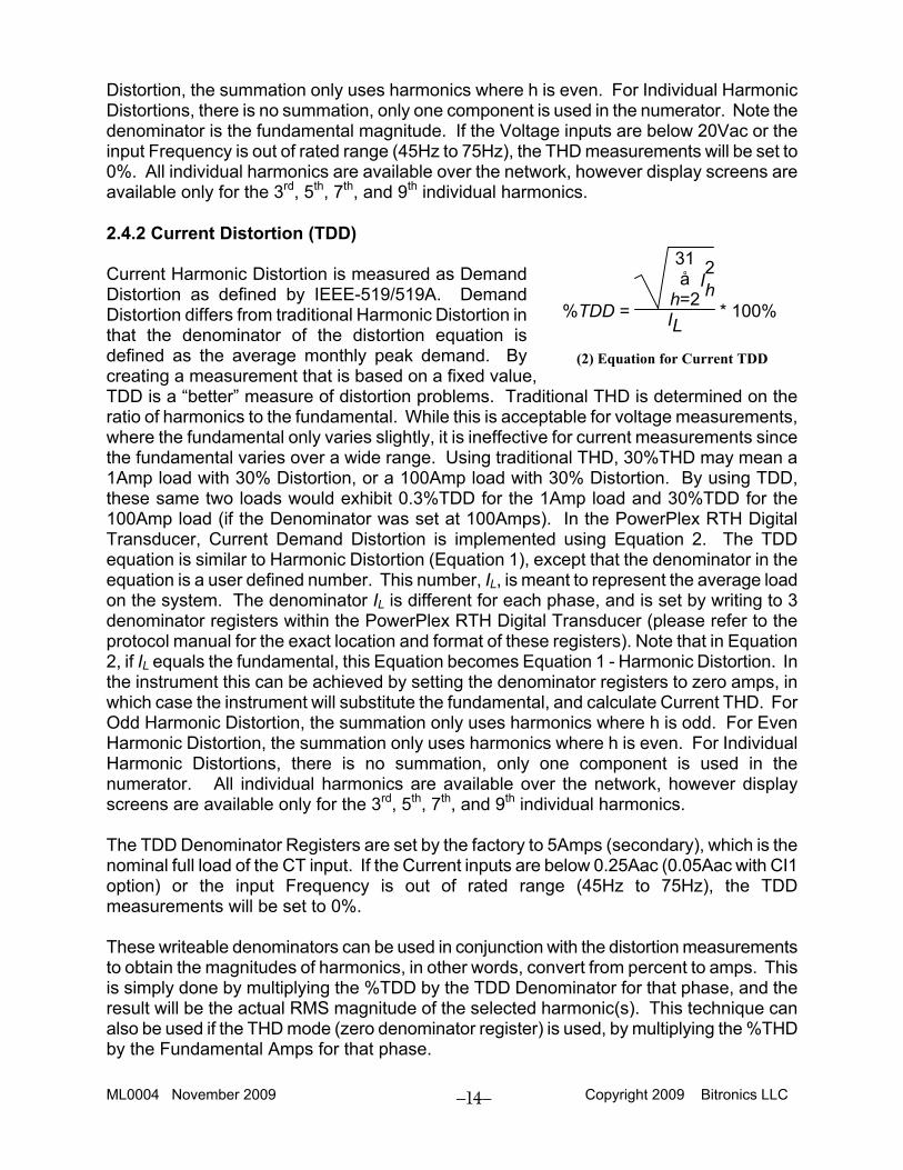
Distortion, the summation only uses harmonics where h is even. For Individual Harmonic Distortions, there is no summation, only one component is used in the numerator. Note the denominator is the fundamental magnitude. If the Voltage inputs are below 20Vac or the input Frequency is out of rated range (45Hz to 75Hz), the THD measurements will be set to 0%. All individual harmonics are available over the network, however display screens are available only for the 3rd, 5th, 7th, and 9th individual harmonics. 2.4.2 Current Distortion (TDD) Current Harmonic Distortion is measured as Demand Distortion as defined by IEEE-519/519A. Demand Distortion differs from traditional Harmonic Distortion in that the denominator of the distortion equation is defined as the average monthly peak demand. By creating a measurement that is based on a fixed value, TDD is a “better” measure of distortion problems. Traditional THD is determined on the ratio of harmonics to the fundamental. While this is acceptable for voltage measurements, where the fundamental only varies slightly, it is ineffective for current measurements since the fundamental varies over a wide range. Using traditional THD, 30%THD may mean a 1Amp load with 30% Distortion, or a 100Amp load with 30% Distortion. By using TDD, these same two loads would exhibit 0.3%TDD for the 1Amp load and 30%TDD for the 100Amp load (if the Denominator was set at 100Amps). In the PowerPlex RTH Digital Transducer, Current Demand Distortion is implemented using Equation 2. The TDD equation is similar to Harmonic Distortion (Equation 1), except that the denominator in the equation is a user defined number. This number, IL, is meant to represent the average load on the system. The denominator IL is different for each phase, and is set by writing to 3 denominator registers within the PowerPlex RTH Digital Transducer (please refer to the protocol manual for the exact location and format of these registers). Note that in Equation 2, if IL equals the fundamental, this Equation becomes Equation 1 - Harmonic Distortion. In the instrument this can be achieved by setting the denominator registers to zero amps, in which case the instrument will substitute the fundamental, and calculate Current THD. For Odd Harmonic Distortion, the summation only uses harmonics where h is odd. For Even Harmonic Distortion, the summation only uses harmonics where h is even. For Individual Harmonic Distortions, there is no summation, only one component is used in the numerator. All individual harmonics are available over the network, however display screens are available only for the 3rd, 5th, 7th, and 9th individual harmonics. The TDD Denominator Registers are set by the factory to 5Amps (secondary), which is the nominal full load of the CT input. If the Current inputs are below 0.25Aac (0.05Aac with CI1 option) or the input Frequency is out of rated range (45Hz to 75Hz), the TDD measurements will be set to 0%. These writeable denominators can be used in conjunction with the distortion measurements to obtain the magnitudes of harmonics, in other words, convert from percent to amps. This is simply done by multiplying the %TDD by the TDD Denominator for that phase, and the result will be the actual RMS magnitude of the selected harmonic(s). This technique can also be used if the THD mode (zero denominator register) is used, by multiplying the %THD by the Fundamental Amps for that phase.
%TDD =
31åh=2
I2h
IL * 100%
(2) Equation for Current TDD
ML0004 November 2009 Copyright 2009 Bitronics LLC
15
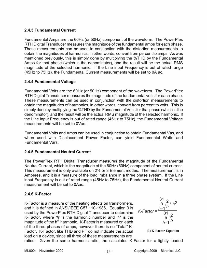
2.4.3 Fundamental Current Fundamental Amps are the 60Hz (or 50Hz) component of the waveform. The PowerPlex RTH Digital Transducer measures the magnitude of the fundamental amps for each phase. These measurements can be used in conjunction with the distortion measurements to obtain the magnitudes of harmonics, in other words, convert from percent to amps. As was mentioned previously, this is simply done by multiplying the %THD by the Fundamental Amps for that phase (which is the denominator), and the result will be the actual RMS magnitude of the selected harmonic. If the Line input Frequency is out of rated range (45Hz to 75Hz), the Fundamental Current measurements will be set to 0A ac. 2.4.4 Fundamental Voltage Fundamental Volts are the 60Hz (or 50Hz) component of the waveform. The PowerPlex RTH Digital Transducer measures the magnitude of the fundamental volts for each phase. These measurements can be used in conjunction with the distortion measurements to obtain the magnitudes of harmonics, in other words, convert from percent to volts. This is simply done by multiplying the %THD by the Fundamental Volts for that phase (which is the denominator), and the result will be the actual RMS magnitude of the selected harmonic. If the Line input Frequency is out of rated range (45Hz to 75Hz), the Fundamental Voltage measurements will be set to 0Vac. Fundamental Volts and Amps can be used in conjunction to obtain Fundamental Vas, and when used with Displacement Power Factor, can yield Fundamental Watts and Fundamental Vars. 2.4.5 Fundamental Neutral Current The PowerPlex RTH Digital Transducer measures the magnitude of the Fundamental Neutral Current, which is the magnitude of the 60Hz (50Hz) component of neutral current. This measurement is only available on 2½ or 3 Element modes. The measurement is in Amperes, and it is a measure of the load imbalance in a three phase system. If the Line input Frequency is out of rated range (45Hz to 75Hz), the Fundamental Neutral Current measurement will be set to 0Aac. 2.4.6 K-Factor K-Factor is a measure of the heating effects on transformers, and it is defined in ANSI/IEEE C57.110-1986. Equation 3 is used by the PowerPlex RTH Digital Transducer to determine K-Factor, where ‘h’ is the harmonic number and ‘Ih‘ is the magnitude of the hth harmonic. K-Factor is measured on each of the three phases of amps, however there is no “Total” K-Factor. K-Factor, like THD and PF do not indicate the actual load on a device, since all three of these measurements are ratios. Given the same harmonic ratio, the calculated K-Factor for a lightly loaded
K-Factor =
31åh=1
I2h * h2
31åh=1
I2h
(3) K-Factor Equation
ML0004 November 2009 Copyright 2009 Bitronics LLC
16
transformer will be the same as the calculated K-Factor for a heavily loaded transformer, although the actual heating on the transformer will be significantly different. If the Current inputs are below 0.25Aac (0.05Aac with CI1 option) or the input Frequency is out of rated range (45Hz to 75Hz), the K-Factor measurements will be set to 1.00. 2.4.7 Displacement Power Factor Displacement Power Factor is defined as the cosine of the angle (phi) between the Fundamental Voltage Vector and the Fundamental Current Vector. Per-phase Displacement Power Factor measurements are available on 2½ or 3 Element modes. The sign convention for Displacement Power Factor is the sign of sin(phi), i.e. a negative Power Factor corresponds to a LAGGING PF and a positive Power Factor corresponds to a LEADING PF. If the Current inputs are below 0.25Aac, the Voltage inputs are below 20Vac or the input Frequency is out of rated range (45Hz to 75Hz), the Displacement Power Factor measurements will be set to 1.999, and the instrument will indicate an over/under-range by blinking the display. The Total Displacement Power Factor measurement is calculated using the "Power Triangle", or the three-phase Fundamental WATTS divided by the three-phase Fundamental Vas. The per-phase Fundamental VA measurement is calculated from the product of the per-phase Fundamental Amp and Fundamental Volts values. In the 2½ and 3-element mode, the three-phase Fundamental VA measurement is the sum of the per-phase Fundamental VA values (Arithmetic VAs). In the 2-element mode, the three-phase VA measurement is calculated from a power triangle VA2 = W2 + VAR2 (Geometric VAs). The sign convention for Total Displacement Power Factor is the opposite sign of the Total Fundamental VARs, i.e. a negative Power Factor corresponds to a LAGGING PF and a positive Power Factor corresponds to a LEADING PF. If all Current inputs are below 0.25Aac (0.05Aac with CI1 option), all Voltage inputs are below 16% of the input range or the input Frequency is out of rated range (45Hz to 75Hz), the Total Displacement Power Factor measurements will be set to 1.999, and the instrument will indicate an over/under-range by blinking the display. 2.4.8 Fundamental Neutral Demand Fundamental Neutral Current Demands are only available in 2½ or 3 Element modes. Present Fundamental Neutral Current Demands are calculated via the sampled data used to calculate the Fundamental Neutral Current. The Present Fundamental Neutral Current Demand and Maximum Fundamental Neutral Current Demand are updated approximately every 600 milliseconds. The Present Fundamental Neutral Current Demand is not displayed but is available via the network interface. Maximum Fundamental Neutral Current Demand is displayed and is also available via the interface. Upon power-up, the Present Fundamental Neutral Current Demands is set to zero. The Maximum Fundamental Neutral Current Demand is initialized to the maximum value recalled from non-volatile memory (EEPROM). Upon DEMAND RESET all the Present and Maximum Fundamental Neutral Current Demands are set to zero. The Fundamental Neutral Current Demands may be reset via the front panel button when the global demand reset screen is enabled or via the network. When the Fundamental Neutral Current
ML0004 November 2009 Copyright 2009 Bitronics LLC
17
Demand is reset via the network, all per-phase Ampere Demands and Fundamental Neutral Current Demand are also reset. 2.4.9 Current TDD Demand Present Current TDD Demands are calculated via the sampled data used to calculate the per phase Current TDDs. The Present Current TDD Demands and Maximum Current TDD Demands are updated approximately every 600 milliseconds. By applying a thermal demand to the TDD measurement, the MultiComm RTH provides a more effective method of determining the severity of a harmonic problem. If a harmonic occurs in a small burst, traditional level detection schemes would alarm. However lower levels of distortion that exist for longer durations actually are more damaging due to the heating effect on transformers. The thermal demand function is an indicator of the thermal effects of the harmonics, and the maximum detector allows the user to assess conditions that occurred at times that were not directly observed. The Present Current TDD Demands are not displayed but are available via the network interface. Maximum Current TDD Demands are displayed and are also available via the interface. Upon power-up, all per-phase Present Current TDD Demands are reset to zero. Maximum Current TDD Demands are initialized to the maximum values recalled from non-volatile memory (EEPROM). Upon DEMAND RESET, all per-phase Present and Maximum Current TDD Demands are set to zero. Current TDD Demands may be reset via the front panel button when the global demand reset screen is enabled or via the network. When Current TDD Demands are reset via the network, Voltage THD Demands are also reset. 2.4.10 Voltage THD Demand Present Voltage THD Demands are calculated via the sampled data used to calculate the per phase Voltage THDs. The Present Voltage THD Demands and Maximum Voltage THD Demands are updated approximately every 600 milliseconds. By applying a thermal demand to the THD measurement, the PowerPlex RTH Digital Transducer provides a more effective method of determining the severity of a harmonic problem. The maximum detector allows the user to assess conditions that occurred at times that were not directly observed. The Present Voltage THD Demands are not displayed but are available via the network interface. Maximum Voltage THD Demands are displayed and are also available via the interface. Upon power-up, all per-phase Present Voltage THD Demands are reset to zero. Maximum Voltage THD Demands are initialized to the maximum values recalled from non-volatile memory (EEPROM). Upon DEMAND RESET, all per-phase Present and Maximum Voltage THD Demands are set to zero. Voltage THD Demands may be reset via the front panel button when the global demand reset screen is enabled or via the network. When Voltage THD Demands are reset via the network, Current TDD Demands are also reset. 2.5 Measurement Resets Certain measurements such as energy and demands may require to be reset. The reset processes are described in this manual. The network reset commands differ depending on
ML0004 November 2009 Copyright 2009 Bitronics LLC
18
which protocol the PowerPlex RTH Digital Transducer supports. Refer to your protocol options manual to obtain the specific network reset commands. 2.5.1 Energy Reset The energy registers can only be reset via the network interface. When reset, all energy registers (positive kilowatthours, negative kilowatthours, positive kilovarhours, and negative kilovarhours) are set to zero. The energy values will be reset within 0.6 seconds, however it takes the meter 4 seconds to clear the energy stored in non-volatile memory (EEPROM). If the power is interrupted to the meter within 4 seconds from the reset request, the reset may not occur. 2.5.2 Demand Resets (RTH Only) Demands can be reset via the network. Demand resets via the network occur in groups (AMPs, VOLTs, POWER, OR HARMONICS). When resetting demands via the network all demands in a group are reset concurrently. The AMP DEMAND NETWORK RESET resets all three phases of Amp Demand, Neutral Current Demand and Fundamental Neutral Current Demand. The VOLT DEMAND NETWORK RESET resets the minimum and maximum of all three phases of Volt Demands. The POWER DEMAND NETWORK RESET resets the minimum and maximum of Total Watt, Total VAR and Total VA Demands. The HARMONIC NETWORK RESET resets the Voltage THD Demands and the Current TDD Demands. Refer to the protocol options manual for the specific network demand reset required. The demand values will be reset within 0.6 seconds, however it takes the meter up to 10 seconds to clear the demand values stored in non-volatile memory (EEPROM). If the power is interrupted to the meter within 10 seconds from the reset request, the reset may not occur.
ML0004 November 2009 Copyright 2009 Bitronics LLC
19
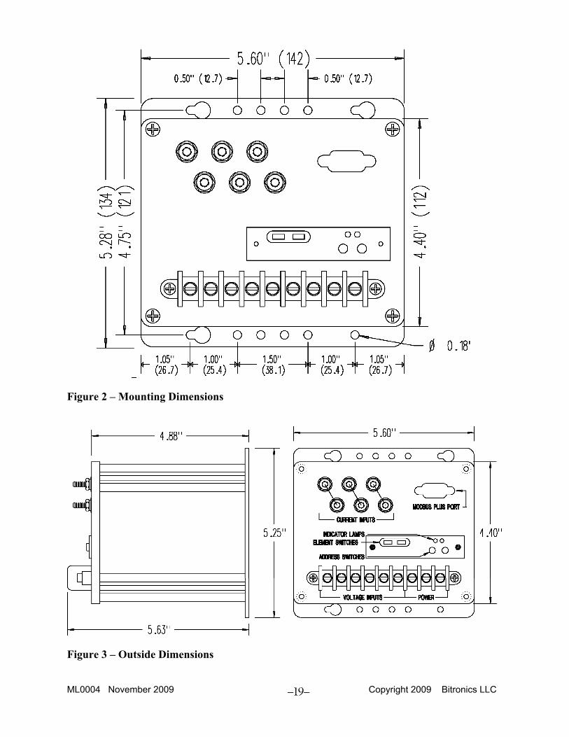
Figure 2 – Mounting Dimensions
Figure 3 – Outside Dimensions
ML0004 November 2009 Copyright 2009 Bitronics LLC
20
3.0 INSTALLATION
WARNING - INSTALLATION AND MAINTENANCE SHOULD ONLY BE PERFORMED BY PROPERLY TRAINED OR QUALIFIED PERSONNEL.
3.1 Initial Inspection Bitronics' instruments are carefully checked and "burned in" at the factory before shipment. Damages can occur, however, so please check the instrument for shipping damage as it is unpacked. Notify Bitronics immediately if any damage has occurred, and save any damaged shipping containers. 3.2 Grounding There are two chassis ground points that MUST be connected to Earth Ground. One is terminal #7 (next to the Power inputs), and the other is the transducer mounting flange. Bitronics recommends that all grounding be performed in accordance with ANSI/IEEE C57.13.3-1983. The Ground terminal #7 is connected to the Line (+) terminal #8 through a 0.01uF UL listed capacitor, not with an MOV, in order to preserve ground isolation when the unit is operated from DC station battery service. 3.3 Power and Input Signal Connections 3.3.1 Power Supply Connections Power and chassis ground is applied to three #8 screws on a barrier strip on the front of the instrument. Connection of the chassis ground is required; see Section 3.2. Because of the solid state design, the total load required to operate the unit is less than six WATTs. An external transient suppression board is mounted on the three power terminals of the barrier strip. It provides an MOV from Line(+)-to-Neutral(-), and a capacitor from Line(+)-to-Ground. Note that the marking of “Neutral” on terminal #9 is for reference only. It is not required to connect the unit from Line-to-Neutral when the unit is powered from an AC source; it may be connected to any AC source, provided the input and isolation voltages are not exceeded. 3.3.1a Universal Power Supply (-VD10) See Section 2.1.3a for complete description of the Universal supply operation. The Universal power supply can operate from any voltage between 20 to 280V dc, or 55 to 200V ac. It is therefore possible to power the PowerPlex Digital Transducer with AC or DC station power or an auxiliary PT, provided the voltage remains above 55 V ac or 20 V dc. 3.3.1b AC Power Supply (-VA3, -VA5, and -VA9 ) See Section 2.1.3b for complete description of the AC supply operation. The nominal line voltages are listed in the Specifications, Section 1.3.
ML0004 November 2009 Copyright 2009 Bitronics LLC
21
3.3.2 Current Input (CT) Connections The impedance at the PowerPlex current (CT) terminals is nearly a short circuit (2 milliohms). These ideal impedances provide low burden loads for the CT circuits supplying the signals. The PowerPlex Digital Transducers have three independent current inputs, one for each phase being measured. Current signals are connected directly to #10-32 brass studs on the front panel of the instrument. WARNING - DO NOT over tighten the nuts on the input connections, HAND tighten with a standard nutdriver, 12 inch-pounds is recommended, MAXIMUM torque is 15 inch-pounds. The instrument can be connected directly to current transformer (CT). Grounding of CT signals per ANSI/IEEE C57.13.3-1983 is required. 3.3.3 Voltage Input (PT) Connections Voltage signals are connected to the #8 screws on the barrier terminal strip on the front of the unit. The impedance at the PowerPlex voltage (PT) terminals is high impedance ( > 100 K-ohms for MTW_3B, or > 400K-ohms for MTW_N1B & MTW_N2B ). These ideal impedances provide low burden loads for the PT circuits supplying the signals. The polarity of the applied signals is important to the function of the instrument, and the signal terminals are labeled LO or HI to aid in wiring the units into substation or control panels. A wiring diagram is also provided in the form of a decal on the side of the unit. Grounding of PT & CT signals per ANSI/IEEE C57.13.3-1983 is recommended. 3.4 Overcurrent Protection A UL recognized 1.5 Ampere non-time delay (M) fuse is to be series connected in the ungrounded (hot) side of mains input as part of installation of this product. 3.5 Mains Disconnect Equipment shall be provided with a Mains Disconnect, that can be actuated by the operator and simultaneously open both sides of the mains input line. The Disconnect shall be UL Recognized and acceptable for the application. 3.6 Instrument Mounting The instrument may be mounted on a standard transducer mounting hole pattern if desired. See Figures 2 and 3. The unit should be mounted with four #8-32 screws. Make sure that any paint or other coatings on the panel do not prevent electrical contact. The transducer is intended to be connected to earth ground at the mounting plate. See section 3.2. 3.7 Surge Protection It is recommended that a metal oxide varistor (MOV) be placed across the power supply input to protect the meter in the event of high voltage surges or lightning strikes. PowerPlex Digital Transducers are shipped with a transient suppression network already attached as a standard design. An MOV provides an added measure of protection against heavy switching transients occasionally experienced in the field. The MOV is designed to
ML0004 November 2009 Copyright 2009 Bitronics LLC
22
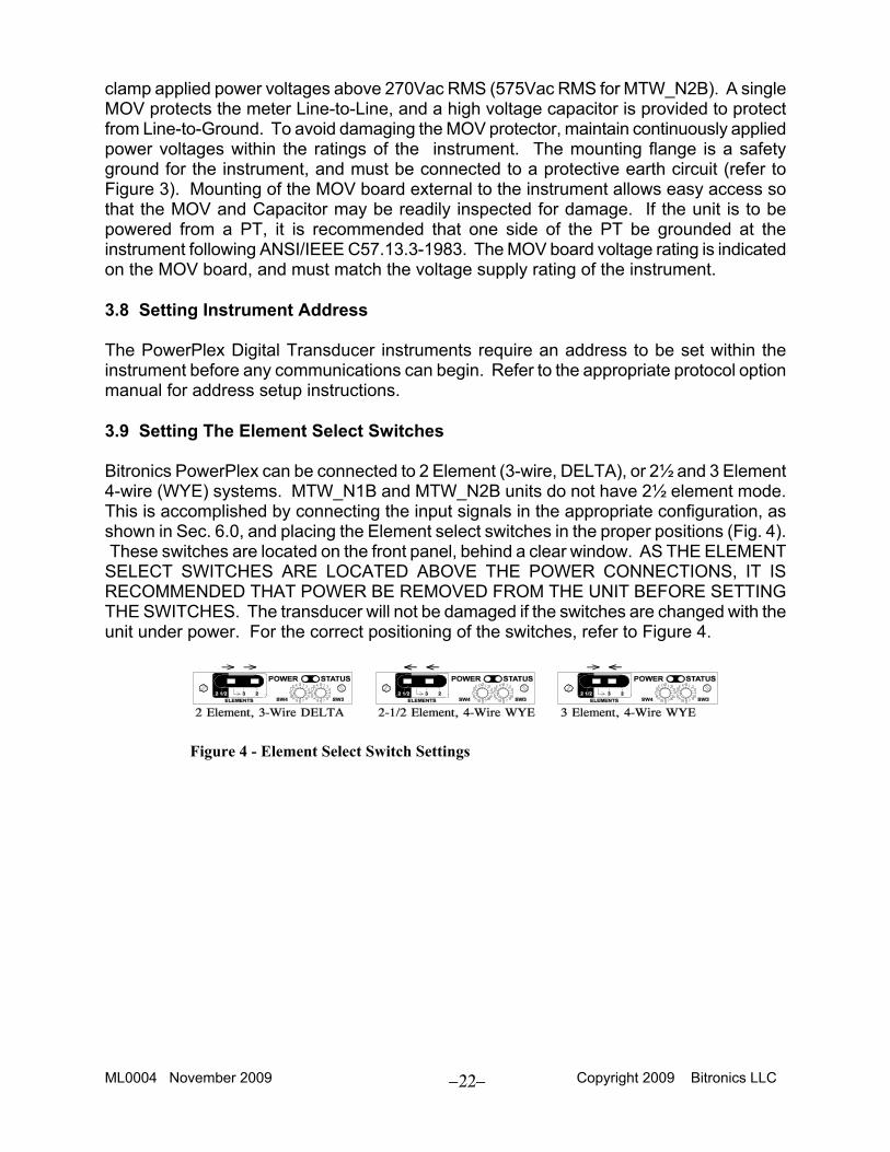
clamp applied power voltages above 270Vac RMS (575Vac RMS for MTW_N2B). A single MOV protects the meter Line-to-Line, and a high voltage capacitor is provided to protect from Line-to-Ground. To avoid damaging the MOV protector, maintain continuously applied power voltages within the ratings of the instrument. The mounting flange is a safety ground for the instrument, and must be connected to a protective earth circuit (refer to Figure 3). Mounting of the MOV board external to the instrument allows easy access so that the MOV and Capacitor may be readily inspected for damage. If the unit is to be powered from a PT, it is recommended that one side of the PT be grounded at the instrument following ANSI/IEEE C57.13.3-1983. The MOV board voltage rating is indicated on the MOV board, and must match the voltage supply rating of the instrument. 3.8 Setting Instrument Address The PowerPlex Digital Transducer instruments require an address to be set within the instrument before any communications can begin. Refer to the appropriate protocol option manual for address setup instructions. 3.9 Setting The Element Select Switches Bitronics PowerPlex can be connected to 2 Element (3-wire, DELTA), or 2½ and 3 Element 4-wire (WYE) systems. MTW_N1B and MTW_N2B units do not have 2½ element mode. This is accomplished by connecting the input signals in the appropriate configuration, as shown in Sec. 6.0, and placing the Element select switches in the proper positions (Fig. 4). These switches are located on the front panel, behind a clear window. AS THE ELEMENT SELECT SWITCHES ARE LOCATED ABOVE THE POWER CONNECTIONS, IT IS RECOMMENDED THAT POWER BE REMOVED FROM THE UNIT BEFORE SETTING THE SWITCHES. The transducer will not be damaged if the switches are changed with the unit under power. For the correct positioning of the switches, refer to Figure 4.
Figure 4 - Element Select Switch Settings
ML0004 November 2009 Copyright 2009 Bitronics LLC
23
4.0 FIELD ADJUSTMENTS
WARNING - INSTALLATION AND MAINTENANCE SHOULD ONLY BE PERFORMED BY PROPERLY TRAINED OR QUALIFIED PERSONNEL.
4.1 Rescaling The PowerPlex Digital Transducer has the capability to store values for Current Transformer (CT) and Potential Transformer (PT) turns ratios. The PT and CT values are factory set to 5:5 CT and 1:1 PT. The PT ratios on MTW_N1B and MTW_N2B instruments are fixed at 2:1 and 4:1 respectively, and cannot be changed. These values can be entered into the PowerPlex over the network, and will be stored in internal non-volatile memory. Energy values are multiplied by these ratios before they are accumulated. The method of writing these values to the transducer will vary depending on the network protocol. Please refer to the appropriate Interface Option Manual for details. 4.2 Calibration Routine recalibration is not recommended, or required. However some drift or aging may cause slight errors after years of use. Additionally, users may wish to have a PowerPlex Transducer "agree" with other instruments. To accommodate both these instances, a "Master Gain" trimpot has been provided. This trim adjusts the overall scale factor by +/- 10%, and is accessed in the following manner:
1. Remove the hole plug on the front of the unit. Insert a small screwdriver through the opening, and into the slot of the screw on the trimpot.
2a. With the unit powered, AND WITH A PRECISION KNOWN INPUT, rotate the screw clockwise to increase the measurement, or counter-clockwise to decrease the indicated measurement. The PowerPlex transducers can be calibrated with a single phase source; for 3 Element (WYE) and 2 Element (DELTA) mode all current inputs should be connected in series, and all potential inputs should be connected in parallel. The Neutral (Residual) Current (in 3 Element Mode only) is the sum of the three-phase currents. In a single phase configuration the currents will all add in phase, therefore the currents should be kept below 5Aac if all three-phases are energized with a single phase source. These restrictions are only for single phase testing.
2b. When units set to 2½ Element (WYE) Mode are connected to a single phase voltage source, they should be connected as shown in Fig 10. Note that the internally generated phase B voltage will be the sum of phase A and phase C. The input voltage should be kept below 75V ac in this single phase configuration, in order to keep from exceeding the 150V ac maximum input level on phase B. Additionally, when testing single phase, the phase C current should be reversed to keep the phase B Watts value the same polarity as phase A and C. Note that with this configuration, the total WATTs and VARs will be 4X the per-phase values. These restrictions are only for single phase testing.
ML0004 November 2009 Copyright 2009 Bitronics LLC
24
4.3 Self Test Modes The PowerPlex instruments are based on a microcontroller, and therefore can capitalize on the power of such a device. One of the areas where the power of the microcontroller enhances the overall performance of the instrument is in the area of "self-testing". The PowerPlex Digital Transducers have several self tests built in to assure that the instrument is performing accurately. If problems are detected during self test, the appropriate error code is transmitted over the network. See the Interface Options manual for your protocol for details. Table I in the appropriate output option manual lists possible faults that would be detected by the self tests, the effects of the fault, and any necessary corrective actions. 4.4 Cleaning Cleaning the exterior of the instrument shall be limited to the wiping of the instrument using a soft damp cloth applicator with cleaning agents that are not alcohol based, and are nonflammable, nonexplosive.

ML0004 November 2009 Copyright 2009 Bitronics LLC
25
5.0 QUESTIONS AND ANSWERS 1. What happens if the applied CT signal exceeds 5A?
The PowerPlex transducers are accurate to twice the normal full scale limit (to 10A). The unit will operate at 100% overload without damage and the communications output is still accurate.
2. Is routine calibration necessary?
No, nor is it recommended. More problems are caused by improper calibration than by faulty meters. A calibration check every few years in the field is good assurance, however.
3. HI and LO are marked on the inputs. Does polarity matter?
Yes! Correct wiring with proper polarity is essential for proper operation. 4. Can I put PowerPlex transducers in an outdoor cabinet?
Yes. Many Bitronics transducers are installed that way. The temperature range of -20C to 70C covers most applications. The case is not waterproof, so it must be placed within an enclosure that provides ingress protection acceptable for the application in accordance with IEC 529, UL840 or the equivalent NEMA Standard.
5. How long will PowerPlex transducers save the CT/PT ratio without power?
The data is saved in a nonvolatile memory (EEPROM) which does not require battery backup. Retention is estimated by the manufacturer to exceed 10 years without refreshing. In any event, long enough to exceed an outage, or for any inactive storage period.
ML0004 November 2009 Copyright 2009 Bitronics LLC
26
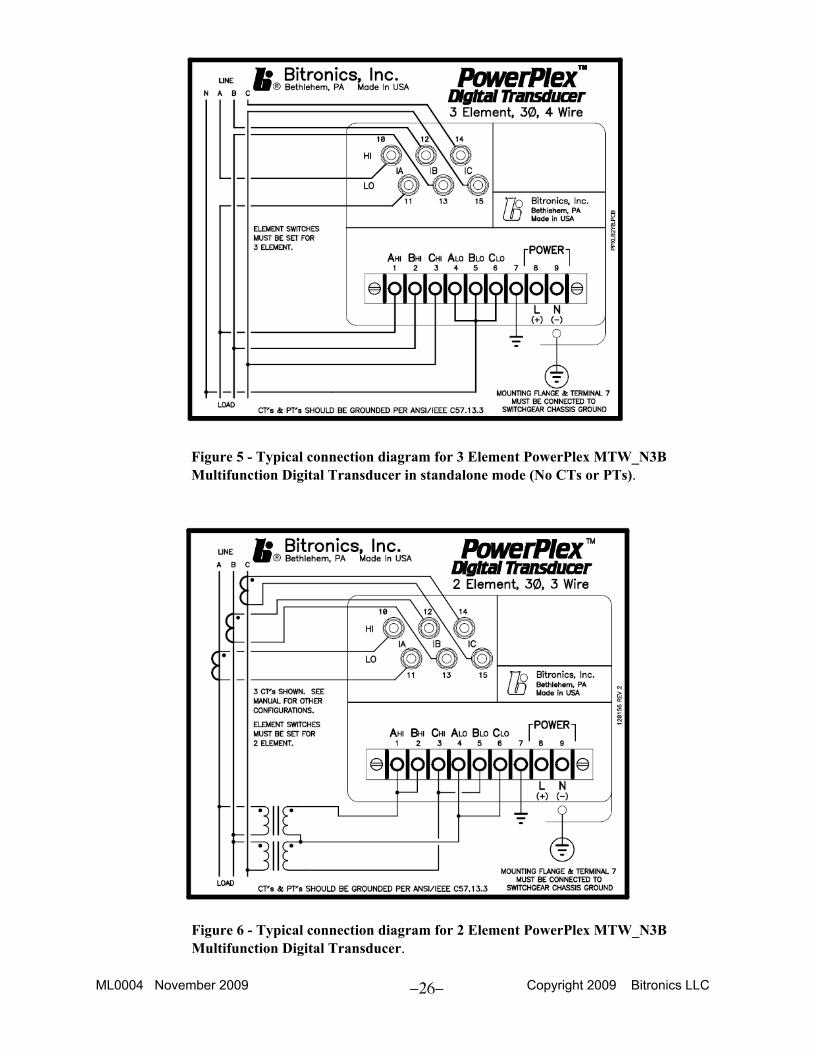
Figure 5 - Typical connection diagram for 3 Element PowerPlex MTW_N3B Multifunction Digital Transducer in standalone mode (No CTs or PTs).
Figure 6 - Typical connection diagram for 2 Element PowerPlex MTW_N3B Multifunction Digital Transducer.
ML0004 November 2009 Copyright 2009 Bitronics LLC
27
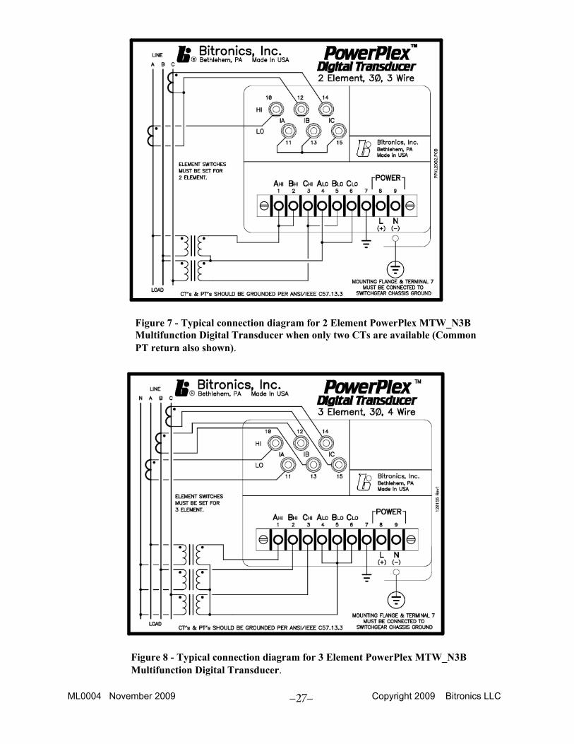
Figure 7 - Typical connection diagram for 2 Element PowerPlex MTW_N3B Multifunction Digital Transducer when only two CTs are available (Common PT return also shown).
Figure 8 - Typical connection diagram for 3 Element PowerPlex MTW_N3B Multifunction Digital Transducer.
ML0004 November 2009 Copyright 2009 Bitronics LLC
28
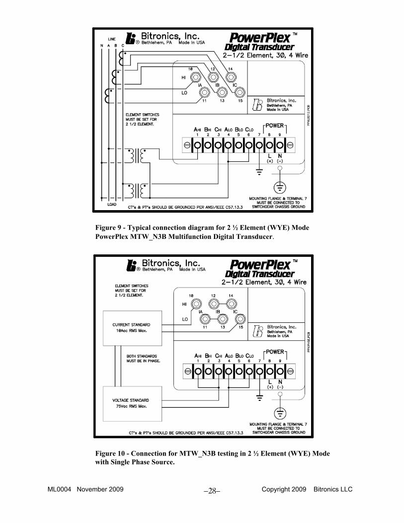
Figure 9 - Typical connection diagram for 2 ½ Element (WYE) Mode PowerPlex MTW_N3B Multifunction Digital Transducer.
Figure 10 - Connection for MTW_N3B testing in 2 ½ Element (WYE) Mode with Single Phase Source.
ML0004 November 2009 Copyright 2009 Bitronics LLC
29
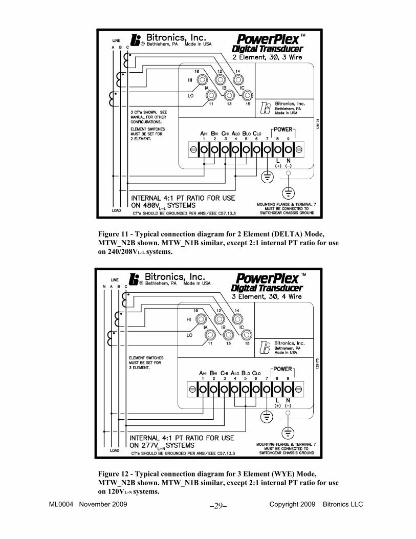
Figure 11 - Typical connection diagram for 2 Element (DELTA) Mode, MTW_N2B shown. MTW_N1B similar, except 2:1 internal PT ratio for use on 240/208VL-L systems.
Figure 12 - Typical connection diagram for 3 Element (WYE) Mode, MTW_N2B shown. MTW_N1B similar, except 2:1 internal PT ratio for use on 120VL-N systems.

Revision Date Changes By A 01/30/2009 Update Bitronics Name, Logo E. Demicco B 11/11/2009 Updated logos and cover page MarCom C

Bitronics LLC. 261 Brodhead Road, Bethlehem, PA. 18017 (610) 997-5100 Fax (610) 997-5450
www.novatechweb.com/bitronics