Embed Size (px)
Citation preview

POWERJECTION IIIInstallation Instructions & User Manual
for 70020, 70021, 70026, & 70027 Kitsand 70028, 70029 plus 70120 through 70129 Kits
Professional Products12705 S. Van Ness Avenue
Hawthorne, CA 90250Tech: 323-779-2020
www.professional-products.com
70027 Kit Shown. Other kits will vary
slightly in appearance and kit contents.
The appearance of the fuel inlet kit portion
of this system may vary from this photo.
Entire Contents - Copyright 2010
TM
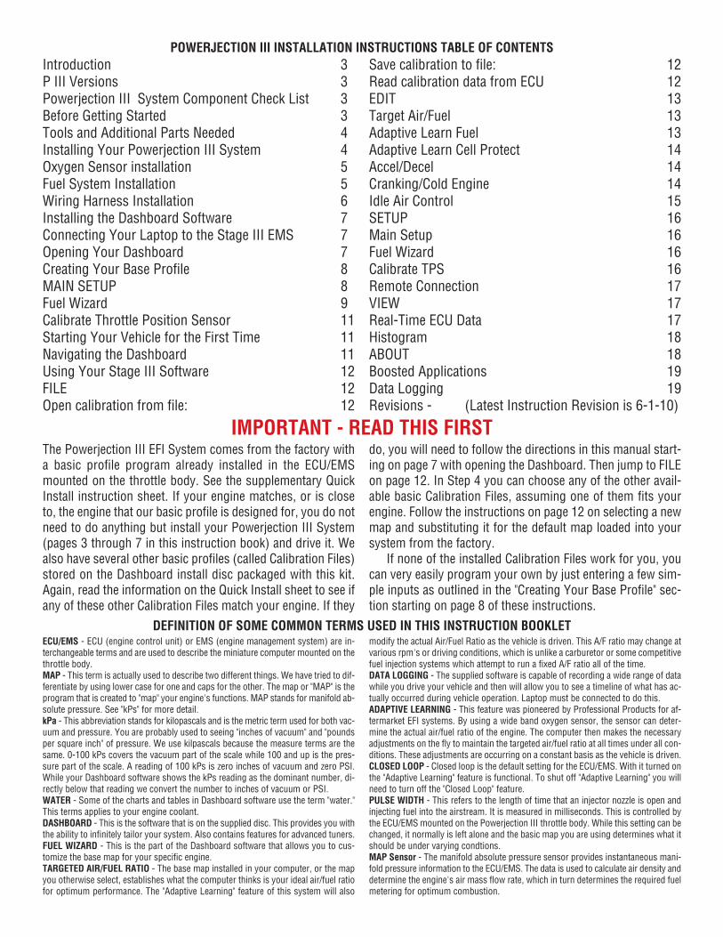
Introduction 3P III Versions 3Powerjection III System Component Check List 3Before Getting Started 3Tools and Additional Parts Needed 4Installing Your Powerjection III System 4Oxygen Sensor installation 5Fuel System Installation 5Wiring Harness Installation 6Installing the Dashboard Software 7Connecting Your Laptop to the Stage III EMS 7Opening Your Dashboard 7Creating Your Base Profile 8MAIN SETUP 8Fuel Wizard 9Calibrate Throttle Position Sensor 11Starting Your Vehicle for the First Time 11Navigating the Dashboard 11Using Your Stage III Software 12FILE 12Open calibration from file: 12
Save calibration to file: 12Read calibration data from ECU 12EDIT 13Target Air/Fuel 13Adaptive Learn Fuel 13Adaptive Learn Cell Protect 14Accel/Decel 14Cranking/Cold Engine 14Idle Air Control 15SETUP 16Main Setup 16Fuel Wizard 16Calibrate TPS 16Remote Connection 17VIEW 17Real-Time ECU Data 17Histogram 18ABOUT 18Boosted Applications 19Data Logging 19Revisions - (Latest Instruction Revision is 6-1-10)
POWERJECTION III INSTALLATION INSTRUCTIONS TABLE OF CONTENTS
IMPORTANT - READ THIS FIRST
DEFINITION OF SOME COMMON TERMS USED IN THIS INSTRUCTION BOOKLET
The Powerjection III EFI System comes from the factory witha basic profile program already installed in the ECU/EMSmounted on the throttle body. See the supplementary QuickInstall instruction sheet. If your engine matches, or is closeto, the engine that our basic profile is designed for, you do notneed to do anything but install your Powerjection III System(pages 3 through 7 in this instruction book) and drive it. Wealso have several other basic profiles (called Calibration Files)stored on the Dashboard install disc packaged with this kit.Again, read the information on the Quick Install sheet to see ifany of these other Calibration Files match your engine. If they
do, you will need to follow the directions in this manual start-ing on page 7 with opening the Dashboard. Then jump to FILEon page 12. In Step 4 you can choose any of the other avail-able basic Calibration Files, assuming one of them fits yourengine. Follow the instructions on page 12 on selecting a newmap and substituting it for the default map loaded into yoursystem from the factory.
If none of the installed Calibration Files work for you, youcan very easily program your own by just entering a few sim-ple inputs as outlined in the "Creating Your Base Profile" sec-tion starting on page 8 of these instructions.
ECU/EMS - ECU (engine control unit) or EMS (engine management system) are in-terchangeable terms and are used to describe the miniature computer mounted on thethrottle body. MAP - This term is actually used to describe two different things. We have tried to dif-ferentiate by using lower case for one and caps for the other. The map or "MAP" is theprogram that is created to "map" your engine's functions. MAP stands for manifold ab-solute pressure. See "kPs" for more detail.kPa - This abbreviation stands for kilopascals and is the metric term used for both vac-uum and pressure. You are probably used to seeing "inches of vacuum" and "poundsper square inch" of pressure. We use kilpascals because the measure terms are thesame. 0-100 kPs covers the vacuum part of the scale while 100 and up is the pres-sure part of the scale. A reading of 100 kPs is zero inches of vacuum and zero PSI.While your Dashboard software shows the kPs reading as the dominant number, di-rectly below that reading we convert the number to inches of vacuum or PSI. WATER - Some of the charts and tables in Dashboard software use the term "water."This terms applies to your engine coolant. DASHBOARD - This is the software that is on the supplied disc. This provides you withthe ability to infinitely tailor your system. Also contains features for advanced tuners. FUEL WIZARD - This is the part of the Dashboard software that allows you to cus-tomize the base map for your specific engine. TARGETED AIR/FUEL RATIO - The base map installed in your computer, or the mapyou otherwise select, establishes what the computer thinks is your ideal air/fuel ratiofor optimum performance. The "Adaptive Learning" feature of this system will also
modify the actual Air/Fuel Ratio as the vehicle is driven. This A/F ratio may change atvarious rpm's or driving conditions, which is unlike a carburetor or some competitivefuel injection systems which attempt to run a fixed A/F ratio all of the time.DATA LOGGING - The supplied software is capable of recording a wide range of datawhile you drive your vehicle and then will allow you to see a timeline of what has ac-tually occurred during vehicle operation. Laptop must be connected to do this.ADAPTIVE LEARNING - This feature was pioneered by Professional Products for af-termarket EFI systems. By using a wide band oxygen sensor, the sensor can deter-mine the actual air/fuel ratio of the engine. The computer then makes the necessaryadjustments on the fly to maintain the targeted air/fuel ratio at all times under all con-ditions. These adjustments are occurring on a constant basis as the vehicle is driven.CLOSED LOOP - Closed loop is the default setting for the ECU/EMS. With it turned onthe "Adaptive Learning" feature is functional. To shut off "Adaptive Learning" you willneed to turn off the "Closed Loop" feature. PULSE WIDTH - This refers to the length of time that an injector nozzle is open andinjecting fuel into the airstream. It is measured in milliseconds. This is controlled bythe ECU/EMS mounted on the Powerjection III throttle body. While this setting can bechanged, it normally is left alone and the basic map you are using determines what itshould be under varying condtions.MAP Sensor - The manifold absolute pressure sensor provides instantaneous mani-fold pressure information to the ECU/EMS. The data is used to calculate air density anddetermine the engine's air mass flow rate, which in turn determines the required fuelmetering for optimum combustion.

Thank you for your purchase of the Professional Products PowerjectionIII Fuel Injection System. In this manual we will outline the procedure for in-stalling the unit on your vehicle as well as how to navigate and use the StageIII Dashboard software.We feel this is the easiest system to install and uti-
lize. If during the installation you have any question about the installationprocedure, please call our Technical Support Line at 323-779-2020. TheTechnical staff is fully equipped and knowledgeable to assist you with everystep of the installation and programming.
The Powerjection III is available in two different versions. The Throttle bodyassembly part numbers 70020 (Satin Finish) & 70021 (Polished Finish)come without any fuel system. These part numbers will require the user tosupply the following components:• EFI Rated Fuel Pump • EFI Rated 10 micron Fuel Filter • Fuel Pressure Reg-ulator • Fuel Pressure GaugeThese versions were designed for those who already have existing compo-nents or wish to supply their own components.
The second version part numbers 70026 (Satin Finish) & 70027 (Polish Fin-ish) come with the above listed components as an "all inclusive" package forthose needing all the components.
INTRODUCTION
BEFORE GETTING STARTED
VARIOUS POWERJECTION III VERSIONS
70020 ShownSatin Finish
70027 ShownPolished Finish 70107 70108
All systems will require the use of a return fuel line. A return fuel line is aseparate fuel line that allows unused fuel to return back to the fuel tank. Weoffer a return fuel line kit part number 70107 for use with the PowerjectionIII systems. This kit includes 25-feet of -06AN stainless braided fuel line andall necessary -06AN hose ends and fittings to plumb the fuel pump, fuel fil-ter and to connect to the EFI system. Note that any of the Powerjection IIIsystems can be converted to a returnless setup by incorporating our 70035FuelOnDemand Kit. This kit also provides many other features that extend the
life of your electric pump and also lessen the pump noise at idle or lowspeeds, particularly on very large pumps. We also offer our 70108 Fuel LineKit for use with returnless systems.
All Powerjection III systems are tested live in a test engine cell to en-sure they are fully operational as part of the extensive quality control meas-ures maintained throughout the entire build process of the Powerjection IIIsystem. Butterflies are adjusted and the idle is set for you on a running en-gine. (Set for a SB engine - you may need some minor adjustment.)
Powerjection III Fuel Injection System Component Check List
1. Throttle body with EMS and dual feed inlet2. Throttle body mounting gasket 3. Air cleaner mounting gasket4. Coolant temperature sensor5. Wide-band O² sensor6. Sub-harness7. O² sensor bung8. Bung gasket9. (2) Worm gear clamps for installing O² sensor bung10. Stage III Dashboard Software CD11. Installation / User manual 12. USB to Serial Cable Adapter 13. Fuel Pressure Regulator (70026/70027 Only)14. Fuel Pressure Gauge (70026/70027 Only)15. Fuel Pump (70026/70027 Only)16. Fuel Filter (70026/70027 Only)We recommend the installation of a pre-filter to avoid damaging thefuel pump in case you have foreign particles in the gas tank. Note thatmost small filters sold for EFI systems will not work properly. We havetested a number of common filters and they cause fuel cavitation anderratic operation. We recommend the Professional Products #10210 or#10211 Inline Filter.
Check the list at the right to make sure you have all the necessary compo-nents required to make up the kit.
Almost all EFI systems require a vented fuel tank. This system is no excep-tion. The fuel tank MUST be vented and the use of a vented fuel cap WILLNOT be sufficient. Minimum vent size should be 1/4-inch. This system alsorequires a return fuel line from the throttle body unit back to the fuel tank.(Unless you are also incorporating our FuelOnDemand kit) It is necessary toinstall a vent and provisions for the return fuel line if these are not alreadypresent. If these modifications need to be performed, remove the fuel tankusing the vehicles manufacturer's guidelines and have experienced person-nel make the modifications. If any welding is performed on the tank it mustbe fully flushed all gasoline and gasoline fumes.
The Powerjection III throttle body will fit the common square-bore intakemanifold that a Holley 4150 will fit. The linkage of the throttle body is thesame as a Holley 4150 so there should be no need to modify the linkage forthe accelerator if the vehicle is presently equipped with a Holley. Carbure-tor adapters can be purchased from speed shops to adapt your intake to the4150 square bore. If you have a spread bore carburetor style manifold youcan utilize a Professional Products #52111 Manifold Adapter Plate Kit toallow the Powerjection III to fit your manifold.
3
The tools required to install the Powerjection III EFI systems are commonhand-tools (Excluding tools for modifications to install a fuel vent and fuelreturn port in the fuel tank). You will need a wire stripper/crimper and a
small assortment of wire terminals and wire.While we attempt to supply every neededcomponent with these systems, each vehi-cle application may require different style(s)of terminals and thus are not included. Readthrough the installation process prior tostarting the installation and determine thestyle and quantity of terminals needed foryour specific application. On the Powerjec-tion III system if you have power brakesand/or a transmission vacuum modulatoryou will need the appropriate vacuum splice
or "T" to connect to a 3/8-inch vacuum port. These are available at most autoparts stores. The fuel pump and EFI supplied inline filter require male 1/4-NPT fittings. The fuel lines need to be a minimum of a 3/8-inch hose or -06AN hose. All fuel lines on the pressureside of the fuel pump to the throttle body arerequired to be EFI pressure rated hose andwe highly recommend the use of factory steellines or AN style fittings and hose. Note thatProfessional Products offers a full line ofhose and fittings including a 1/4-NPT x 3/8barbed fitting (#10244) specifically designedto be used with the supplied Powerjection IIIEFI fuel pump, and filter. See the Profes-sional Products website for fittings and hose.www.professional-products.com
TOOLS AND ADDITIONAL PARTS YOU MAY NEED
INSTALLING THE POWERJECTION III EFI SYSTEM
Use Professional Products1/4-NPT x -06AN fitting infuel pump and filter if using -06AN hose. #15239 (blue)or 16239 (black) or #17239(polished).
Use Professional Products1/4-NPT x 3/8 hose barbedfitting if you are using slip-on and clamped fuel hoselines. This type of fitting isrequired on pressure side.
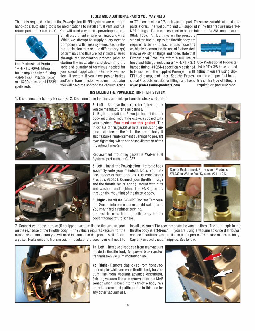
3. Left - Remove the carburetor following thevehicle manufacturer's guidelines. 4. Right - Install the Powerjection III throttlebody insulating mounting gasket supplied withyour system. You must use this gasket. Thethickness of this gasket assists in insulating en-gine heat affecting the fuel in the throttle body. Italso features reinforcement bushings to preventover-tightening which can cause distortion of themounting flange(s).
Replacement mounting gasket is Walker FuelSystems part number G1037
5. Left - Install the Powerjection III throttle bodyassembly onto your manifold. Note: You mayneed longer carburetor studs. Use ProfessionalProducts #20151. Connect your throttle linkageand the throttle return spring. Mount with nutsand washers and tighten. The EMS groundsthrough the mounting of the throttle body.
6. Right - Install the 3/8-NPT Coolant Tempera-ture Sensor into one of the manifold water ports.You may need a reducer bushing.Connect harness from throttle body to thecoolant temperature sensor.
7a. Left - Remove plastic cap from rear vacuumnipple in throttle body for power brake and/ortransmission vacuum modulator line.
7b. Right - Remove plastic cap from front vac-uum nipple (white arrow) in throttle body for vac-uum line from vacuum advance distributor.Existing vacuum line (red arrow) is for the MAPsensor which is built into the throttle body. Wedo not recommend putting a tee in this line forany other vacuum use.
1. Disconnect the battery for safety. 2. Disconnect the fuel lines and linkage from the stock carburetor.
7. Connect your power brake (If equipped) vacuum line to the vacuum porton the rear base of the throttle body. If the vehicle requires vacuum for thetransmission modulator you will need to connect to this port as well. If botha power brake unit and transmission modulator are used, you will need to
install a vacuum T to accommodate the vacuum lines. The port nipple in thethrottle body is a 3/8-inch. If you are using a vacuum advance distributor,connect distributor vacuum line to upper port on front base of throttle body.Cap any unused vacuum nipples. See below.
Sensor Replacement: Professional Products#71230 or Walker Fuel Systems #211-1012.
4

OXYGEN SENSOR INSTALLATION
FUEL DELIVERY SYSTEM INSTALLATION
8. Below Left - If no previous oxygen sensor was used; locate a suitable lo-cation to install the supplied oxygen sensor bung. The location should bejust past where the head pipe connects to the exhaust manifold. If headersare used, make sure it is about 4-6 inches past the collector pipe. If it isplaced in the exhaust on a horizontal pipe, make sure that the angle of thesensor mounting is between the 9 o’clock and (going over the top to the) 3o’clock position (this prevents condensation and exhaust debris from pos-sibly contaminating the sensor). Drill a 5/8-inch hole. Open both supplied
hose clamps, place on exhaust pipe and start the worm-gear hose clamps.Place the supplied gasket over the hole and place the stainless steel bungover the gasket holding it in place and tighten the hose clamps to securethe bung. OPTIONAL: You can weld the bung into place without the use ofthe gasket and clamps. 9. Below Right - Plug the harness cable from thethrottle body into the cable from the Oxygen Sensor. Using cable ties, keepharness away from exhaust or moving parts. Oxygen sensor replacement number is Walker Fuel Systems 250-25022
Professional Products #71250 Clamp-OnOxygen Sensor Bung Kit. The bung itselfis made of stainless steel and can either beclamped on or welded on to exhaust.
The supplied fuel pump and the EFI fuel filter (70026 & 70027 only) have ¼-female pipe threads on the inlet & outlets. You will need to supply the fittingsnecessary for each of these to connect your fuel lines to. These fittingsMUST BE 3/8-inch / -06AN size or larger. Install the fittings into the fuel fil-ter using blue Loctite #246. Never use Teflon tape in the fuel system. If youhave also purchased either a #70107 or #70108 Fuel Line Kit, these kits willhave all the necessary fittings you need.
Remove the fuel inletand outlet fittings fromthe fuel pump. Installyour pre-selected fit-tings into the removedfittings using blue Loc-tite #246 sealant. Neveruse Teflon tape in thefuel system. If you at-tempt to install your fuelline fittings into the inlet
and outlet fittings of the pump with the fittings still installed in the pump, youmay damage the pump.
Reinstall the fuel inlet fitting onto the fuel pump taking care to not over-tighten.
Next install the brass outlet fitting on to thepump making sure the sealing washer is inplace.
Tighten the outlet fitting, taking caution notto over-tighten. The inlet threads are fragileand may break if over-tightened.
Install the fuel pump. The fuel pump mustbe mounted in a position below the fuel tank level and within (2) feet ofthe fuel tank so that fuel can gravity feed and prime the pump. This is trueof all electric EFI fuel pumps, not just the Professional Products pump.
Connect a ground wire on the negative side of the fuel pump and ground tothe chassis.
Install a fuel line from the fuel tank supply outlet to the fuel pump inlet. A
pre-filter should NOT be used inline between the fuel supply and the fuelpump inlet unless you have the correct filter. Many of the commonly avail-able filters used before the fuel pump will cause a vacuum between the pumpand filter. This vacuum situation will cause the fuel to aerate and cavitate in-side the pump. Using the stock sock/screen type filter located in the gastank will be sufficient incatching any large debristhat can cause damage tothe fuel pump. However, ifyou feel you want to use apre-filter we have testedand had good luck with theProfessional Products#10210 (red/blue) or#10211 (aluminum) InlineStreet Filter. This filter has3/8-NPT ports and you canuse a pair of Professional Products #10232 (2 to a pack) 3/8" hose nipple fit-tings. This filter is used on the low pressure side of the pump so ordinaryhose nipple fittings and clamps are suitable.
Install a fuel line from the pump outlet to the supplied (70026 / 70027 only)EFI inline fuel filter. If you are supplying your own fuel filter, it must be EFIrated and filter to 10 microns.
Install a fuel line from the EFI filter to the fuel inlet onthe right front of the Powerjection III throttle body.NOTE: All Fuel lines from the fuel pump to the fuelpressure regulator need to be a minimum size of 3/8inch inside diameter hose or -06AN lines and mustbe rated for high pressure fuel injection use.
NOTE: The fuel pump and all fuel lines need to bemounted and / or shielded and routed away from anyheat source which may create vapor lock.
Install a return fuel line from the fuel tank forward to the bottom of the fuelpressure regulator and connect. (It is not required that the return fuel line beEFI rated). Note: If using a regulator not supplied with your system, be sureyou know which port is for the return.
#70151 Pump Suppliedin EFI Kit.
Inlet
Outlet
Return line connectsto bottom of regulator
Inlet line connects tothis end of fuel inlet kit
#10210 Pre-Filter
Outlet
The above instructions are extremely important and must be followed. Please carefully read the above instructions and make sure that you perform all of the steps exactly as outlined.
Extreme high temperature gasket
5
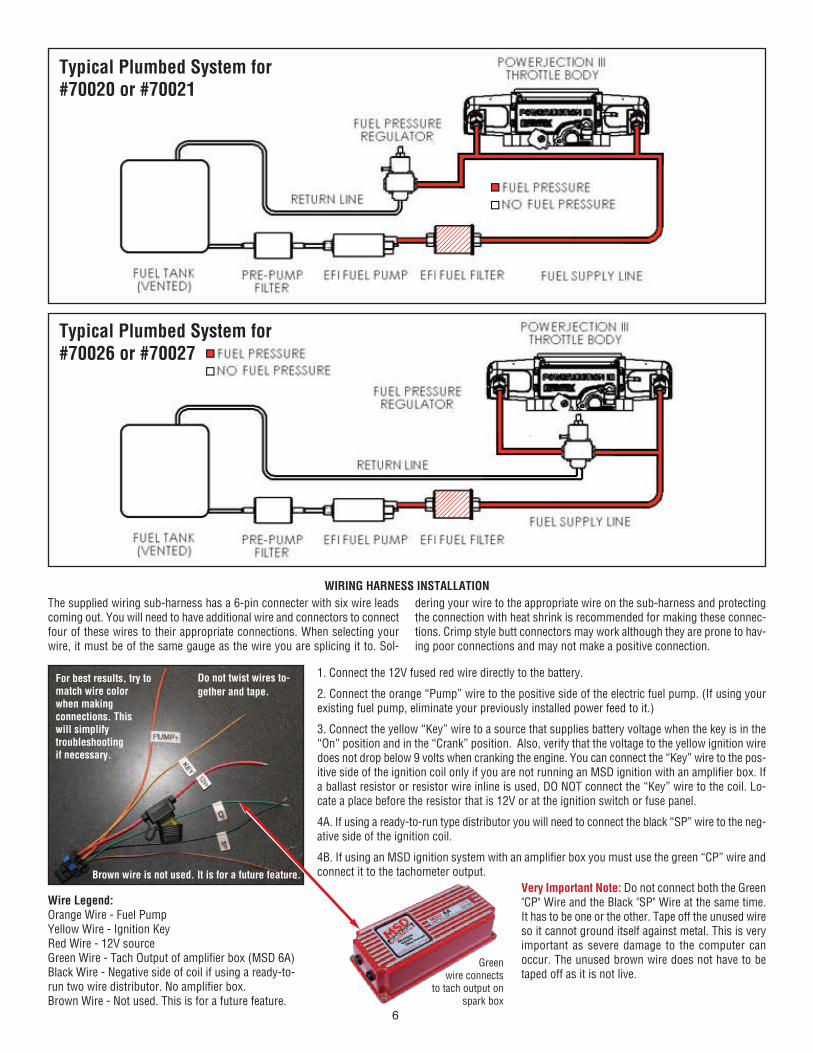
Typical Plumbed System for#70020 or #70021
Typical Plumbed System for#70026 or #70027
WIRING HARNESS INSTALLATION
The supplied wiring sub-harness has a 6-pin connecter with six wire leadscoming out. You will need to have additional wire and connectors to connectfour of these wires to their appropriate connections. When selecting yourwire, it must be of the same gauge as the wire you are splicing it to. Sol-
dering your wire to the appropriate wire on the sub-harness and protectingthe connection with heat shrink is recommended for making these connec-tions. Crimp style butt connectors may work although they are prone to hav-ing poor connections and may not make a positive connection.
For best results, try tomatch wire colorwhen making connections. This will simplifytroubleshootingif necessary.
Do not twist wires to-
gether and tape.
Brown wire is not used. It is for a future feature.
1. Connect the 12V fused red wire directly to the battery.
2. Connect the orange “Pump” wire to the positive side of the electric fuel pump. (If using yourexisting fuel pump, eliminate your previously installed power feed to it.)
3. Connect the yellow “Key” wire to a source that supplies battery voltage when the key is in the“On” position and in the “Crank” position. Also, verify that the voltage to the yellow ignition wiredoes not drop below 9 volts when cranking the engine. You can connect the “Key” wire to the pos-itive side of the ignition coil only if you are not running an MSD ignition with an amplifier box. Ifa ballast resistor or resistor wire inline is used, DO NOT connect the “Key” wire to the coil. Lo-cate a place before the resistor that is 12V or at the ignition switch or fuse panel.
4A. If using a ready-to-run type distributor you will need to connect the black “SP” wire to the neg-ative side of the ignition coil.
4B. If using an MSD ignition system with an amplifier box you must use the green “CP” wire andconnect it to the tachometer output.
Wire Legend:Orange Wire - Fuel PumpYellow Wire - Ignition KeyRed Wire - 12V sourceGreen Wire - Tach Output of amplifier box (MSD 6A)Black Wire - Negative side of coil if using a ready-to-run two wire distributor. No amplifier box.Brown Wire - Not used. This is for a future feature.
Very Important Note: Do not connect both the Green"CP" Wire and the Black "SP" Wire at the same time.It has to be one or the other. Tape off the unused wireso it cannot ground itself against metal. This is veryimportant as severe damage to the computer canoccur. The unused brown wire does not have to betaped off as it is not live.
Green wire connects
to tach output on spark box
6

1. You need to make sure you have the battery negative cable grounded tothe engine block and that you have a quality engine to chassis / body groundstrap. An improper ground connection will result in erratic performance.2. The vehicles battery must be fully charged. Be sure the throttle body isproperly tightened and secured with lock washers.3. Re-install and connect the battery. Turn the key to the “ON” position onlyand look for any visible fuel leaks. If you have fuel leaks, correct before pro-
ceeding any further with the installation.4. Adjust the fuel pressure by turning the adjustment screw on top of the fuelpressure regulator to 42-45 PSI as read on the fuel gauge. If the initial read-ing is higher, you may need to turn the key off and bleed the pressure off byloosening the fuel supply line to the fuel inlet rail and reducing the fuel pres-sure. Adjust and test for proper fuel pressure again.5. Do not attempt to start the vehicle at this time.
FINAL STEPS TO THE MECHANICAL PORTION OF THE INSTALLATION
INSTALLING THE DASHBOARD SOFTWARE
OPENING THE DASHBOARD ON YOUR LAPTOP
1. The supplied software is designed to be used with the Powerjection IIIand is compatible with the Windows 7 operating system. You will need a PClaptop with a CD drive to complete the installation. 2. Insert the supplied Dashboard CD into the CD drive. The Install Wizard willpop up and guide you through the installation process. If the Wizard does
not pop up, go to My Computer and double click the drive the CD is in. Thenthe Install Wizard should pop up to continue the install process. Once thesoftware is installed into your laptop, you will need to connect it to the Pow-erjection III throttle body harness.3. See photos and notes below to complete this stage of the installation.
Cable from throttle body. Shownwith dust cap removed. Replace dust cap when disconnected from laptop.
Ignition key should beoff when these connec-tions are made.
The two cables shown above will allow you toconnect your laptop to the Powerjection III.
Connect the USB end of the cable to the USBport in your laptop
Connect the other end of the cable assembly intothe single pin connector from the throttle body.
1. The icon at leftwill be on your lap-top desktop. Clickon it to open yourDashboard soft-ware.
2. When the Dashboard opens,you will see the window at rightthat tells you the Dashboard issearching through 29 CommPorts to locate the Stage III ECU(ECU is the computer mountedon your throttle body).
3. If the Dashboard cannot find your ECU a blank Dashboard screen willcome up. If you get a blank screen, then in order to connect to your StageIII ECU you can either turn your key to the "on" position and hit the “Connectto ECU” button to start the ECU search again, or you can close and re-openthe Dashboard program with the key "on" to commence the new auto search.When the Dashboard finds the ECU you will see a window come up asshown above with the word "Connecting" in yellow. See above left image.
4. When fully connected to the ECU the status will change from the yellow"Connecting" to the green "ECU Connected." See above right image. A pop-up in the middle of the screen lets you know the system is reading the ECU
calibration files. When the load status completes, the pop-up goes away andyou are now online with your Powerjection III ECU.
NOTE: The Powerjection III ECU has a run profile already loaded in itsmemory. The Dashboard software also comes with additional profiles inthe Calibration File Folder. The already installed run profile is set up for300 HP small block Chevy with a medium rise street manifold and a stockto mild cam. If your engine is close to this profile (it doesn't have to be asmall block Chevy) you can skip to the "Starting Your Vehicle for the FirstTime" section on page 11. We still suggest you read through the next fewpages so you are familiar with what your EFI can do.
7

CREATING YOUR BASE "PROFILE" FOR THE POWERJECTION III EFI SYSTEM
We will take you through the steps necessary to create your custom profileand get your vehicle started. Most applications require answering a fewquestions only and will not require an advanced calibration. The only timeyou may need to do an advanced calibration is if your engine is very radicalwith a big cam.
In the “Using Your Stage III Software” section we will break down and de-fine what each item on each page represents and how to alter it for tuning
your particular vehicle.
To create your first base map program, make sure your laptop is connectedto the Stage III EMS as explained earlier, then turn your ignition key "on" andclick the “Dashboard” icon on your desktop. The main screen will appear.See image at below left. Then select "Setup" from the menu at the top of thescreen and then select "Main Setup." See image at below right. You will thenget the Main Setup screen shown below.
MainSetup
The Main Set Up screen will appear as shown above. There are several in-puts that may need to be made. Details on each will be given below. • MAP Boundaries Note: Default values are for unblown applications.• RPM Boundaries Note: Default value is 4500 RPM• Cylinder Selection (# of cylinders) 8 is the default setting.• Tuning Strategy Automatic is the default setting.• Tach Input Coil (-) is the default setting.• Closed Loop On is the default setting.
• Adaptive Learning On is the default setting.• Idle Cell Setup (Defaults): Enabled, RPM less than: 1250, TPS less than:
2, MAP less than: 100NOTE: Do not adjust “Fuel Blend Offset %." This is for future development.If you are using E85 contact technical support at 323-779-2020.For the last four (Tuning strategy, Tach input, closed loop and adaptivelearning) you will need to left-click to toggle button icon and it will togglebetween the two available choices.
MAP & RPM: For un-blown applications,leave the MAP and
RPM boundary tablesat the default settings.We will further explain
the setup for theseboundaries in "Boosted
Applications" section.
Fuel Blend: The de-fault setting is gaso-line. This system is
capable of operatingon E85 and various
blends of gasoline andE85. Please call the
Professional Productstech department if youwant to run something
other than gasoline.
Cylinder Selection: Select the number of cylin-ders of your engine; 4, 6, or 8. Eight is default.
8

Tuning Strategy:Please select "Auto-
matic" so that thecomputer can generatethe fuel curve. We willdiscuss "Manual Tun-ing" in the Advanced
Tuning Section ofthese instructions.
Closed Loop: The de-fault setting should be
"On." If not, toggle to"On." Toggling is ac-
complished by placingyour cursor over the
toggle switch and leftclicking your mouse.
Tach Input: Select "6ATach" if using an ampli-fier spark box (MSD orother) and you used thegreen wire. Or "Coil (-)"if connecting the distrib-utor reference black wireto the coil. Engine mustbe "off" and ignitionswitch "On" to changethe Tach Input.
Adaptive Learn-ing: The defaultsetting shouldbe "On." If not,toggle to "On."
Note: This section is for advanced tuners only.For most applications, the adjustments outlinedhere to the Idle Cell are not necessary.
Idle Tuning: The Idle Tuning strategy allows youto setup a specific idle cell that is separate fromthe fuel map. This allows you to specify a sepa-rate desired air/fuel mixture for when the engine isin an idle situation.Idle Cell Enabled: This feature can be enabled ordisabled by simply adding or removing the checkmark in the Idle Cell Enabled check box.
Fixed PW: By checking the Fixed PW box you canset a fixed desired pulse width for idle. This fea-ture can be used for an engine that has a lot ofvalve overlap/rough idle. It can also be used as atrouble shooting tool to fix the fuel delivery at idleto diagnose a non-fuel related problem.
There are specific values that need to be met toachieve the idle cell:RPM Must be less than the number in the box.TPS Must be less than the number in the box.MAP Must be less than the number in the box.
Above: It is very important that you select the "TachInput" to match the way you wired the green or blackwires from your EFI system. See page 6 of instructions.
FUEL WIZARD
When the "Fuel Wizard" window opens (see above right) you will need to setseveral options as follows:
• Estimated Maximum RW Torque (or actual if known)• Number of injectors. (This will be 4 unless running a dual EFI)• Boost (if supercharged or turbocharged)• Injector Flow Rate (Default is 62 lbs/hr.)• Intake Manifold Type (We provide selections for you)• Camshaft Type (We provide selections for you)
Torque: The first value to be entered (see chart above right, torque box ishighlighted) is Torque. This needs to be a realistic value. If you are runninga stock engine the torque values can be researched online. If you have a
crate engine the supplier of the engine should have supplied you with a max-imum torque rating. If you don't know what your maximum torque figure is,try to find a crate motor listing that is similar to your engine and use thatnumber. If you enter a wrong value it can be changed later. If you put in toohigh of a number the engine will run rich, too low and it will run lean. Thedefault number is 300 (lb/ft). To change it, double click on the number fortorque, enter your value and and click outside the area to save it. We usetorque because it represents the fuel required by the engine. The numbershould be the maxium rear wheel torque of your engine. Horsepower is amath equation derived from torque and RPM and does not provide an ac-curate fuel requirement for your engine like a torque listing does.
Next select "Fuel Wizard' from the Setup. See image at below left.
9
Note on Torque Specs: Many torque figures given in engine spec sheets are flywheel torque. Our profiles use rear wheel torque. If you start with a fly-wheel torque value, reduce it by 20% for the purposes of developing your engine’s profile. For a quick approximation of your engine torque go to theProfessional Products website (www.professional-products.com) and then click on “Handy Formulas.” See “CID To Torque Comp Ratio” chart.

Number of Injectors: This value will always be four unless you are runningone of our dual EFI setups and then it will be eight.
Boost: If your engine is normally aspirated (unblown) the value is zero andthat is the default. If running a blower, then enter the maximum boost yourengine is set up to produce.
Injector Flow Rate: This value will always be 62 unless you have a customsetup with different flow rate injectors. If you have something other than 62lb./hr. injectors, enter the correct number in this box.
Intake Type: Choose from the following: 1. Stock/Cyclone/Performer/Ac-tion+Plus, 2. Typhoon/Performer RPM/Stealth, 3. Crosswind/Air Gap, 4.Hurricane/Victor/Super Victor/Team G.
Camshaft: Choose based on engine vacuum. Stock 16-18" • Mild Stock 15-17" • Street Performance 14-16" • Performance RPM 13-15" • Hot Street11-14" • Strip/Street 9-12" • Pro-Street/Race 6-10" • Boost 14-16"Note: After you start your engine and your vacuum reading is different fromwhat you entered, go back and select the correct cam type based on actualvacuum reading and then recalculate the base map. (Calculating is shownat right.) Left click on "Cam Type" slider and drag from left to right . You willsee the camshaft name and vacuum reading appear above the slider. Justslide it to your desired vacuum reading.
Calculate: The last step in creating a base profile is to apply all the enteredinformation. Verify that the "Slider" is in the unlocked position. If not, leftclick on the toggle switch. It will read "Slider Unlocked." Now, with it un-locked, left click on the "Calculate" button. You will see a change in the bargraph on the screen. This is your new profile. Now lock the slider by leftclicking on it. This will prevent inadvertant changes to your base profile.Note: We will explain how to move the bar sliders in the "Using YourStage III Software" section. Now close out of the Fuel Wizard by clicking"Close" in the lower right corner of the screen.
10

CALIBRATING THE THROTTLE POSITION SENSOR
STARTING YOUR VEHICLE FOR THE FIRST TIME WITH THE POWERJECTION III EFI SYSTEM
NAVIGATING THE DASHBOARD
This next step is to Calibrate theThrottle Position Sensor (TPS). Clickon "Setup" and select "Calibrate TPS."
If you accidentally click on "Calibrate TPS Max" be-fore the minimum calibration has been fully set,the above window will alert you to that fact. Thenyou need to repeat the "Calibrate TPS Min" step.After both Min and Max have been set, close theSet TPS window by clicking on "Close" in lowerright corner of window.
The TPS Calibration window will open. With the accel-erator released and the throttle fully closed, press the"Calibrate TPS Min" button. Next depress the accelera-tor pedal fully to the floor and while fully held down,click the "Calibrate TPS Max" button.
Note: When you turn the key to the “on” position, you will hear the fuelpump come on for a few seconds and then shut off. This is normal. TheEMS needs to receive a distributor reference signal when the engine isturning over to maintain power to the fuel pump. This is a safety featurebuilt into the system in case the vehicle is in an accident and the enginestops; power is shut off to the fuel system.
1. Turn the key on. Confirm that the fuel pump activates and shuts off aftera couple of seconds.2. Check again for fuel leaks and repair as needed.3. Start the engine. And let it idle and come up to a temperature of about 150degrees.4. Check and adjust the fuel pressure to 45 pounds as necessary. To adjust,turn the regulator top adjustment screw clockwise for more pressure andcounter-clockwise for less pressure. On non-boosted applications, do notconnect a vacuum line to the pressure regulator. The nipple fitting on theregulator is a vent. Do not cap or plug it.
Note: These adjustment steps are for the fuel pressure regulator suppliedwith the fuel system, if using another brand of regulagtor, consult with themanufacturer for proper instructions on changing the pressure.
5. Note the idle RPM. The idle RPM warm (engine temp 180° minimum),should be 900 – 1000 RPM. If adjustment is needed read below. Note, whenmaking idle adjustments, place tape over IAC hole in top of throttle body.
The Primary and secondary throttle shafts need to move in an almost 1:1ratio. If you need to make an adjustment you will need to adjust the pri-mary and secondary idle screws the same. Keep in mind that adjusting onescrew to the desired RPM will not work properly. You need to adjust the pri-mary to a 50% increase or decrease from the actual RPM to the desiredRPM then adjust the secondary screw to the final desired RPM. After the de-sired RPM is set, you will need to recalibrate the throttle position sensor(TPS) following the same steps as outlined above in the “Creating your pro-file”
Note: With the engine off and air cleaner off, you should be able to lookdown in the bores of the throttle body and see that the openings for the pri-mary throttle blades and secondary throttle blades are opened the sameamount.
6. Install an appropriate sized air cleaner ¼-20 stud into the throttle body.7. Install the supplied air cleaner mounting gasket and your air cleaner mak-ing sure to secure properly. Drive your vehicle and enjoy!
Now that you have driven your car for some period and have given the"Adaptive Learning" feature the opportunity to dial your Powerjection III sys-tem into your style of driving, you can learn a lot about your system by re-connecting your laptop and checking out the various settings. You can alsomake a wide variety of adjustments in your system if desired. Unless youhave a highly modified engine, the settings that either came as a default orthe new map that these instructions walked you through earlier should pro-vide optimum performance for your vehicle. However, for those of you whowant to delve deeper into the Powerjection III's capabilities, this section isfor you.
When you open the dashboard it will display the telemetry of the engine as
follows:
• MAP / Vacuum Reading • Actual Air Fuel Ratio (In 2 plcs)• Coolant Temperature • Targeted Air Fuel Ratio• R.P.M.When lit up, the status items are active. When not lit, they are not active.These items are:• Key • Adaptive Learning• O2 Sensor • Idle• Closed Loop • Decel
Also displayed is the status of the ECU connection, the button to connect tothe ECU and the toggle to turn data logging on and off.
Air Fuel Ratio: This is displayed intwo locations. It shows numericallythe air to fuel ratio. The sampleshows a 13.7 to 1 air to fuel ratio.
R.P.M. This is the large round dialin the center of the screen. It pro-vides both an analog sweep armand a digital readout.
MAP: The MAP (Manifold AbsolutePressure) is displayed in both kPaand inches of vacuum or PSI. Zeroinches of vacuum equals 100 kPa.
Coolant Temperature: The enginecoolant temperature is expressed indegrees of Fahrenheit.
11

TARGETED AIR/FUEL RATIO: This is displayed beneath thetachometer. It is a digital bar graph showing the actualair/fuel (A/F) ratio at the top and the targeted air/fuel ratio(TGT). The targeted number comes from a table that is de-rived from the information you input to create the base pro-file. The targeted number can also be set manually to yourdesired number. We will discuss setting your desired targetin the "Advanced Tuning" section.
DATA LOGGING: When Data Logging is turned on a com-plete record of your vehicles operation is stored in the com-puter. You can go back at any time and review all of thestored data. Data logging is turned on by toggling the switchshown at right. Switch is white in the down position whenturned off and red in the up position when turned on.
STATUS LIGHTS: The Status Lights will let you know: Idle: In-dicates you are in the idle mode. Decel: Indicates that you arein the Decel Fuel Cutoff mode. Ignition Key Status: When key isin the "On" position the light will be lit. Oxygen Sensor Status:When lit it indicates that the oxygen sensor is working properly.Closed Loop Status: When lit the EMS/ECU is operating inclosed loop. Adaptive Learning Status: When lit, the EMS/ECUis learning and updating.
Status Lights
USING YOUR STAGE III SOFTWARE
FILE
There are a number of adjustments that can be made while driving the carwith your laptop connected to the Powerjection III System. Note: Never at-tempt to make corrections or adjustments to your system while driving
alone. We suggest you have a friend assist. One person drives while theother person monitors the laptop and makes the adjustments. Trying to doit by yourself could lead to losing control of your vehicle.
With your Dashboard open on your laptop, at the top leftyou will see several choices: File, Edit, Setup, View, andAbout. We will discuss each of these various choices indetail on the following pages.
1. Under File you have four options:• Open calibration from file• Save calibration to file• Read calibration data from ECU• Exit
4. The Calibration File Folder will open and then you selectthe file you wish to load into the ECU/EMS. By default, if youdo not see the Calibration Files, go to: C:\Program Files\StageIII Dashboard Software V2_0\StageIII Calibration Files
5. Save Calibration to File: This allows saving the currentloaded calibration in the ECU/EMS with the changes youhave made in your laptop. You need to name the file some-thing descriptive so you can easily recognize it. 6. Enter the file name and date and click "Save."7. Select Read Calibration from File. This downloads thecurrent profile in the ECU/EMS to the Dashboard.8. Select Exit. This closes the Stage III Dashboard.
2. Open Calibration from file: This willopen a window on the laptop that listsstored calibration files and calibrationfiles made and stored by you. Calibra-tion files use the extension ".RSC"
3. A pop-up will appear asking you to confirm that you wish to load a newCalibration File. This will overwrite the current profile in the ECU/EMS.Note: You may wish to save the previous profile in the ECU/EMS to theCalibration File folder before loading in a new file. Click "OK" to save file.
Step 1 Step 2 Step 3
Step 4 Step 5
Step 7
Step 8
Step 6
12
See pages 19 and 20 for completedetails on how to access and usethe Data Logging capabilities ofyour Powerjection III System.
Map for John Doe - 06-15-10

EDIT
Edit: Under Edit you can edit thefollowing:• Target Air/Fuel Ratio• Adaptive Learning Fuel• Adaptive Learning Cell Protect• Accel/Decel• Crank/Cold Engine• Idle Air Control (IAC)
In the Edit portion of the software you can make a number of changesto your Powerjection III EFI System. Please note that most of theitems covered in this section are for advanced users who want to finetune their system for specific uses or for engines that are radicallymodified. If you elected to use the Base Calibration or any of the op-tional calibrations already loaded into the system (see page 12), thenin most instances you will not need to perform any of the adjustmentsor settings outlined in this section of the instruction manual. How-ever, in some instances you may need to make some minor adjust-ment and in that case you will need to utilize the information providedin this section of the instruction manual.
Target Air/Fuel: This table allows you to alter the targeted air to fuel ratiothat the ECU/EMS uses in closed loop. Across the top are the MAP (Mani-fold Absolute Pressure) boundaries and down the left are the RPM bound-aries. Note that each MAP column has two numbers which represent a highand low range. MAP is expressed in kPa. The RPM also has two numbers foreach row which also represents an RPM range. By entering the value youwant in each of the cells allows you to vary your A/F ratio in various rpmranges in concert with various vacuum levels. Note that 10.0 is very richand 20.0 is very lean.
To alter a cell one at a time, double click on the cell and enter a new value.If you want to change all the cells to the same number, double click on thecell below Fill and enter a new number. Then click the Fill button and all thecells will change to that number.
If you want to increase or decrease all the cells by the same percentage, youcan use the Multiply function. To increase all the cells by 10%, enter 1.1 inthe cell below the Multiply button, then click on the Multiply button. All thecells will rise in value by 10% creating a leaner A/F mixture. (A 5% increasewould use a value of 1.05). To decrease all cells by 10% enter 0.9 (5% wouldbe 0.95) and click the Multiply button. All the cells will lower by 5% creat-ing a 5% richer mixture.
When you have finished making all the changes, click on Send to save theentered data to the ECU/EMS. Then click Close to close the window and saveall the changes.
Note: These values directly affect the mathematical formula that drivesyour ECU/EMS. By raising or lowering these values, the output pulse-width will be altered. These values are also used as the target values forClosed Loop and Adaptive Learning.
Adaptive Learn Fuel: This table shows the amount of learning that yourECU/EMS has performed in the specific Load/RPM cell.
Note: In order for this feature to work, you must go to the Main Setup (seepage 8) and switch both "Adaptive Learn Fuel" and "Closed Loop" to theactive status.
The numbers in the cells are expressed in percentages. For example, a cellwith a "30" means that the ECU/EMS has learned that 30% more fuel isneeded to achieve the targeted air/fuel ratio as set in the Air/Fuel table. Itthen adds this 30% to the base profile number to obtain the correct pulsewidth (PW) for the injectors. A "-30" means that the ECU/EMS is subtract-ing 30% of the fuel from the base profile to obtain the correct PW in orderto achieve the target air/fuel ratio.
You may wish to make changes to this table because you have found that aparticular RPM range of your engine combination likes either more or lessfuel in order to get the maximum power and performance.
You can make changes to the learned values if you need to by clicking onEdit. Then by clicking on the cell you want to change you can enter the valueyou want. Changing the value will change the injection pulse width by thepercentage that you enter. Remember these numbers are percentages. Afteryou have made your changes, click on Send to update. Lastly, click Editonce more so the ECU/EMS will make changes automatically.
You can quickly zero all the cells by clicking on the Clear ADL button. A pop-up will appear confirming that you really want to do this. If so, click OK.
Note: Clearing the Adaptive Learn Fuel (by clicking on Clear ADL) willmake them all zero even if the cell(s) are protected. So be very sure thisis what you want to do before proceeding.
13
TARGET AIR/FUEL ADAPTIVE LEARN FUEL

EDIT (continued)
ADAPTIVE LEARN CELL PROTECT ACCEL/DECEL
CRANKING/COLD ENGINE
In the previous Adaptive Learn Fuel table you could enter changes to the in-dividual cells. However as long as the Adaptive Learning feature was turnedon, these cells will change as you drive the vehicle.
The table above allows you to protect/lock the cells that you changed on the"Adaptive Learn Fuel" table. Entering "1" unlocks the cells and the cells canbe altered in the “Adaptive Learn Fuel” table. Note that "1" is the default set-ting so you were able to make the changes without having to unlock the cell.
Entering “0” (Zero) locks that cell and the EMS/ECU will not be able to au-tomatically change the value unless it is unlocked by entering "1."
You can manually double-click a cell and change it from 1 to 0 to lock. Youcan also use the “Fill” option by entering a 1 or 0 and clicking “fill”. This willfill all the cells to the option you chose.
The lock function is used if you have entered a number in the Adaptive LearnFuel Table that you wish to remain constant and not update. For instance,you may have found that increasing or decreasing the value in the AdaptiveLearn Fuel table made the vehicle respond better to your liking, you maywant to lock / protect that cell so that the EMS does not update it.
After making your desired changes, click Send to update the ECU/EMS. Toclose the table, click Close in the lower right hand of the window.
Note: The adjustments made to this window are recommended to bemade by experienced tuners. The default values will work fine for thevast majority of applications. If you experience hesitation issues, adjustthe targeted air fuel ratio for the given RPM/load or add/subtract fuel inthe Adaptive Learn table in the cell which is causing your hesitation.
On the above Accel/Decel table you can adjust the pulse-width for your ac-celeration enrichment, the duration of time you want that percentage added,as well as deceleration fuel cutoff values.
The Acceleration Enrichment (AE) acts like an accelerator pump on a car-buretor, it shoots additional fuel upon the event of a rapid throttle opening.The quicker you open the throttle the more fuel your engine will require.This window allows you to adjust your AE for your specific vehicle.
The AE (Acceleration Enrichment) and the Duration Tables can be rapidlyfilled by using the Fill Low and Fill High buttons.
The acceleration pulse-width cells can not be less than 1100uS (Microsec-onds) or more than 32000uS.
The AE "Fill Low" button will auto-fill the pulse-width entered for the accel-eration from 0 to 12% TPS time. (TPS/5mS - Speed of throttle opening)The duration "Fill Low" will also auto-fill the time (Milliseconds) you wish forthe AE to be in use.
The "Fill High" will auto-fill from 20 –100% the value entered. In the AE tableand also the duration table.
You can independently fill each cell with the desired value by clicking on thecell and entering the value.
To make the values apply, you must click the Send button under each table.
The Decel function is to reduce the fuel injected while decelerating. Youcan enter the pulse-width you desire and at what RPM and throttle angle itbecomes active. After entering the values click Send to update the profile.
After making any adjustments to the tables, you can click Close to close thewindow.
14
In most instances the parameters in this window will not need to be changed.This window allows you to change the cranking fuel, start-up enrichment,cold fuel enrichment and fuel pump prime. The pulse-width for cranking istemperature dependent and the value is in microseconds.
CRANKING - The cranking pulse-width is only active while the engine iscranking and when the engine gets above 401 RPM the profile takes over therunning fuel control. If you are experiencing excessive cranking times youcan adjust this parameter. The “Pump Prime” will turn the fuel pump on when the key-power is turnedon for a period of time (1 to 60 seconds) to prime the system, and then shut off. It will not turn on again until the engine begins cranking over and the ECU/EMS receives a signal from the ignition system.
The “Fuel Prime” can be thought of as an accelerator pump on a carburetorwhen you step on it before starting. The EMS will open the fuel injectors tospray fuel for easier start-ups for a desired amount of time (1 to 60 mil-liseconds). The default value will be sufficient 99% of the time.
You also have the option of choosing when the Fuel Prime occurs. You canchoose to prime the engine while you begin cranking or you can prime aftera specified delay time from when the EMS receives key power.
COLD ENGINE -This section of the window allows for you to add a percent-age of fuel to the profile for cold engines to allow proper running until itreaches operating temperature. This section can be thought of as a chokesystem of a carburetor. (Cold Engine continued on next page)
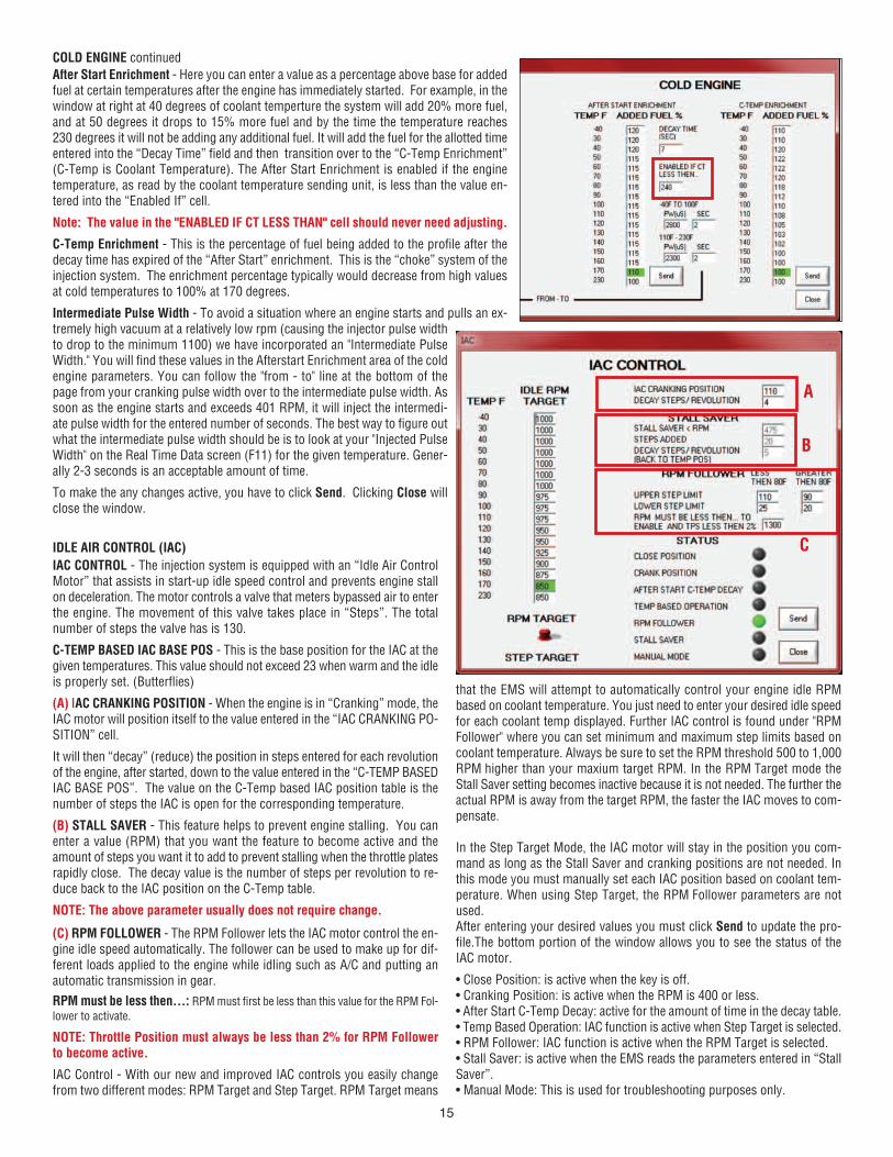
IAC CONTROL - The injection system is equipped with an “Idle Air ControlMotor” that assists in start-up idle speed control and prevents engine stallon deceleration. The motor controls a valve that meters bypassed air to enterthe engine. The movement of this valve takes place in “Steps”. The totalnumber of steps the valve has is 130.
C-TEMP BASED IAC BASE POS - This is the base position for the IAC at thegiven temperatures. This value should not exceed 23 when warm and the idleis properly set. (Butterflies)
(A) IAC CRANKING POSITION - When the engine is in “Cranking” mode, theIAC motor will position itself to the value entered in the “IAC CRANKING PO-SITION” cell.
It will then “decay” (reduce) the position in steps entered for each revolutionof the engine, after started, down to the value entered in the “C-TEMP BASEDIAC BASE POS”. The value on the C-Temp based IAC position table is thenumber of steps the IAC is open for the corresponding temperature.
(B) STALL SAVER - This feature helps to prevent engine stalling. You canenter a value (RPM) that you want the feature to become active and theamount of steps you want it to add to prevent stalling when the throttle platesrapidly close. The decay value is the number of steps per revolution to re-duce back to the IAC position on the C-Temp table.
NOTE: The above parameter usually does not require change.
(C) RPM FOLLOWER - The RPM Follower lets the IAC motor control the en-gine idle speed automatically. The follower can be used to make up for dif-ferent loads applied to the engine while idling such as A/C and putting anautomatic transmission in gear.
RPM must be less then…: RPM must first be less than this value for the RPM Fol-
lower to activate.
NOTE: Throttle Position must always be less than 2% for RPM Followerto become active.
IAC Control - With our new and improved IAC controls you easily changefrom two different modes: RPM Target and Step Target. RPM Target means
that the EMS will attempt to automatically control your engine idle RPMbased on coolant temperature. You just need to enter your desired idle speedfor each coolant temp displayed. Further IAC control is found under "RPMFollower" where you can set minimum and maximum step limits based oncoolant temperature. Always be sure to set the RPM threshold 500 to 1,000RPM higher than your maxium target RPM. In the RPM Target mode theStall Saver setting becomes inactive because it is not needed. The further theactual RPM is away from the target RPM, the faster the IAC moves to com-pensate.
In the Step Target Mode, the IAC motor will stay in the position you com-mand as long as the Stall Saver and cranking positions are not needed. Inthis mode you must manually set each IAC position based on coolant tem-perature. When using Step Target, the RPM Follower parameters are notused. After entering your desired values you must click Send to update the pro-file.The bottom portion of the window allows you to see the status of theIAC motor.
• Close Position: is active when the key is off.• Cranking Position: is active when the RPM is 400 or less.• After Start C-Temp Decay: active for the amount of time in the decay table.• Temp Based Operation: IAC function is active when Step Target is selected.• RPM Follower: IAC function is active when the RPM Target is selected.• Stall Saver: is active when the EMS reads the parameters entered in “StallSaver”.• Manual Mode: This is used for troubleshooting purposes only.
COLD ENGINE continued
IDLE AIR CONTROL (IAC)
After Start Enrichment - Here you can enter a value as a percentage above base for addedfuel at certain temperatures after the engine has immediately started. For example, in thewindow at right at 40 degrees of coolant temperture the system will add 20% more fuel,and at 50 degrees it drops to 15% more fuel and by the time the temperature reaches230 degrees it will not be adding any additional fuel. It will add the fuel for the allotted timeentered into the “Decay Time” field and then transition over to the “C-Temp Enrichment”(C-Temp is Coolant Temperature). The After Start Enrichment is enabled if the enginetemperature, as read by the coolant temperature sending unit, is less than the value en-tered into the “Enabled If” cell.
Note: The value in the "ENABLED IF CT LESS THAN" cell should never need adjusting.
C-Temp Enrichment - This is the percentage of fuel being added to the profile after thedecay time has expired of the “After Start” enrichment. This is the “choke” system of theinjection system. The enrichment percentage typically would decrease from high valuesat cold temperatures to 100% at 170 degrees.
Intermediate Pulse Width - To avoid a situation where an engine starts and pulls an ex-tremely high vacuum at a relatively low rpm (causing the injector pulse widthto drop to the minimum 1100) we have incorporated an "Intermediate PulseWidth." You will find these values in the Afterstart Enrichment area of the coldengine parameters. You can follow the "from - to" line at the bottom of thepage from your cranking pulse width over to the intermediate pulse width. Assoon as the engine starts and exceeds 401 RPM, it will inject the intermedi-ate pulse width for the entered number of seconds. The best way to figure outwhat the intermediate pulse width should be is to look at your "Injected PulseWidth" on the Real Time Data screen (F11) for the given temperature. Gener-ally 2-3 seconds is an acceptable amount of time.
To make the any changes active, you have to click Send. Clicking Close willclose the window.
A
B
C
15

SETUPSetup: Under Setup you can se-lect the following:• Main Setup• Fuel Wizard• Calibrate TPS• Remote Connection
In this section you can make a number of fine tuning adjustments in-cluding tips on how to configure your system if you are running E85gasoline. You can also further refine your fuel delivery by using sliderbars while driving the vehicle as opposed to entering values as previ-ously discussed. This section also discusses calibrating the TPS andhow you can connect your laptop to our technical support personnel sothat we can view what screen is showing at the same time you are look-ing at it. This can be valuable when trouble shooting a problem thatyou cannot resolve on your own or over the phone.
MAIN SETUPMain setup is where you will input values for RPMboundaries and MAP boundaries if you need them todiffer from the default settings. You just double-clickin the cell and then enter the new value. The value forMAP must be kPa values and the vacuum line abovewill change automatically to correspond with the en-tered value affer "Send" is pressed.
You also make the cylinder selection, tuning strategy,learning ability, closed loop and tach input.
TUNING STRATEGYChoosing "Automatic" allows for the EMS to calculatefuel delivery. "Manual" tuning will be discussed in thefuture in an advanced tuners manual.
CLOSED LOOPSelecting Closed Loop "On" allows for the Stage IIIEMS to learn the fuel curve of the engine. In order to work, Adaptive Learn-ing must also be in the "On" position. Closed loop comes on at 40 degreesFahrenheit. In the "Off" position, it will not use the O2 sensor reading in theequation to adjust the fuel delivery. On motors using leaded fuels, the O2
sensor life will be shortened. You may wish to use the O2 for some learn-ing and then turn closed loop off. When Closed Loop is off, the EMS will usethe learned data in the Adaptive Learning to calculate fuel delivery.
Note: Running leaded fuel and turning CL off does not save the sensor
from contamination. You will need to physically remove the sensor andinsert a plug in the bung.
ADAPTIVE LEARNINGWith Closed Loop on and Adaptive Learning on, the ECU/EMS will learn fuelvalues for your engine and place the learned percentage on the AdaptiveLearning Table. If any cells have a value (Learned or manually input) in acell, the ECU/EMS will use the value even if "Closed Loop" is off.
FUEL WIZARD
Under "Setup" select "Fuel Wizard."
We used part of the Fuel Wizard in the "Creating Your First Profile." Herewe will discuss more details about what you can do with the Wizard.
With your engine running you can click on the "UP" or "DN" button to addor remove fuel for a given RPM listed below the bar graph. (No MAP re-lationship)
You may find that your engine will run more efficient by adding or sub-tracting fuel while the engine is in operation.
You should lock the slider prior to making any changes to the bar graph.This prevents you from accidently recalculating which will change anychanges you made to the bar graph.
Q: Why would you want to alter this?
A: It is a quicker method of altering the fuel delivery than typing valuesinto individual cells of the Adaptive Learn Table.
NOTE: If you make changes this way, you need to save this as a pro-file to your laptop.
CALIBRATE TPS
Under "Setup" select "Calibrate TPS." This procedure is used to calibrate the TPS so that theEMS knows what the closed throttle and the fully opened throttle positions are.
To calibrate the throttle position sensor (TPS), click on “Setup” and choose “Calibrate TPS”
The TPS calibration window will open. With the accelerator released and throttle closed, pressthe “Calibrate TPS Min” button. Next fully depress (Push to the floor) the accelerator and whileheld down click the “Calibrate TPS Max” button.
Note: If you accidently click “Calibrate TPS Max” before the minimum calibration has beenset, a pop-up window will display telling you to set the minimum value first.
16

REMOTE CONNECTION
This feature allows you to connect live via the internet to Professional Products Techni-cal Support so that Technical Support can view what you are viewing on your Stage IIIDashboard at the same time live.
To use this function you must have a broadband Internet connection (not dial-up) andcontact Technical Support By phone at (323) 779-2020.
When speaking with you on the phone, Technical Support will supply you verbally theneeded information to input to complete the remote connection.
NOTE: While connected to Technical Support, the support staff has no control of yourlaptop/computer. A member of the support team may suggest/request what changesneed to be done and you, the user, will have to input the information on your laptop.
VIEWView allows you to view:• Real-Time ECU Data• Histogram
Real-Time ECU DataSelecting this allows you to view in real time:• RPM• MAP / Vacuum• Water Temperature• ECU Temperature• Coolant Enrichment• Adaptive Learn Fuel Percentage• Closed Loop Percentage• Cell• Air Fuel Ratio• Targeted Air Fuel Ratio• Battery Voltage• IAC Target• IAC Position• Fuel Usage In Gallons Per Hour• Total Run Time• TPS Position percentage• Maximum Allowed Injector Pulse Width• Injector Pulse Width• Injection Mode• Tach Style Input• Key (on or off)• Fuel Pump Relay (active or non-active)• Oxygen Sensor (Active or non-active)• Closed Loop (Active or non-active)• Adaptive Learning (On or off)• Cranking (In cranking mode or not)• Gasoline, 50% or 100% E85 (Only one of the 3 will be active)• Close Position• Crank Position• After Start Decay• Temp Based Mode• RPM Follower• Stall Saver• Manual Mode
RPM: The Engine speed currently being monitored by the ECU.MAP: The MAP / vacuum reading currently being monitored by the ECU.Water Temp: The coolant temperature of the engine and read by the ECU.Coolant Enrich%: The amount of cold enrichment percentage programmed.Adaptive Learn Fuel %: The percentage value the ECU has learned.Closed Loop%: The Percent of change the closed loop is making toward theAdaptive Learn Fuel.Cell: The current cell that the engine is in.A/F: The air fuel ratio currently read by the oxygen sensor.Target A/F: The programmed targeted air fuel ratio.Battery Volt: The current battery voltage read by the ECU.IAC Target: The programmed target of the Idle Air Control Motor.
IAC POS: The current position of the Idle Air Control Motor.Fuel Usage Gal/Hour: The amount of fuel the engine is using in gallons perhour at that exact time.Total Run Time: The total time the ECU has been active. (Key on power)TPS: The current position of the throttle position sensor.Max Allowed Injector PW (mS): Max allowable Pulse Width at the currentRPM and Load.Injector PW (mS): Injected pulse width at that exact time.Injection Mode: 1. Crank, 2. Auto, 3. Manual, 4. Deccel, 5. Standby (KOEO),6. Clear Flood, 7. Fixed PW, 8. Idle Cell.Tach Input: The input style selected during the setup in setup>main setup.Key: Green indicates the key is on. Black indicates the key is off.Fuel Pump Relay: Green indicates the relay is active. Black is off.O2 Sensor: Green indicates the O2 sensor is being monitored/used. Note: Green does not mean the sensor is good. Over time, oxygen sen-sors will degrade from normal use and need to be replaced. The re-placement interval is approximately 30,000 miles.Adaptive Learn: Green indicates it is turned on. Black indicates off. Thisis turned off or on in the main setup.Cranking: This will be yellow when the engine is cranking only.Gasoline: This is the default value. Only one of the 3 fuel types will be litup green. For E85 use, contact Technical Support.Close Position: When the key is turned off the IAC goes to a Home or"Closed."Crank Position: The IAC motor is in the cranking position.After Start Decay: The IAC motor is decaying from the crank position to thetarget base position.Temp Based Mode: IAC motor position is temperature based.RPM Follower: IAC motor maintains desired engine RPM.Stall Saver: The stall saver feature is active.
17

Here are screen shots of the Dashboard and Real-Time Data. You can see how the values from the Real-Time Data match those on the Dashboard.
HISTOGRAM
ABOUT
This feature allows you to see what is occurring in real time with:
• RPM• TPS• MAP / Vac• Injector Pulse Width• A / F (Air Fuel Ratio)• Battery Voltage
Also displayed are the peak value the EMS recorded during the currentkey-on /run session. Under the MAP screen is a choice of "NA" and"BOOST." Click the appropriate one for your application. It changes thescale for load on the left side of the MAP screen.
Clicking “Reset All” will reset the peak values that have been recorded.If you are data logging, you can click “Bookmark” to mark a specific lo-cation you saw while observing the histogram for ease in finding whilereviewing the data log
Bookmark Button - Bookmarking can be used for troubleshooting. Withthe Histogram open, press the Bookmark button when the issue oc-curs and a placemark will be saved in the log file. (You must be datalogging at the time in order for this to occur.)
About opens a box displaying informa-tion about:• Dashboard Version• Release Date• Calibration File Version• Firmware Version• Comm Port the ECU is using.
18
BOOSTED APPLICATIONS
DATA LOGGING
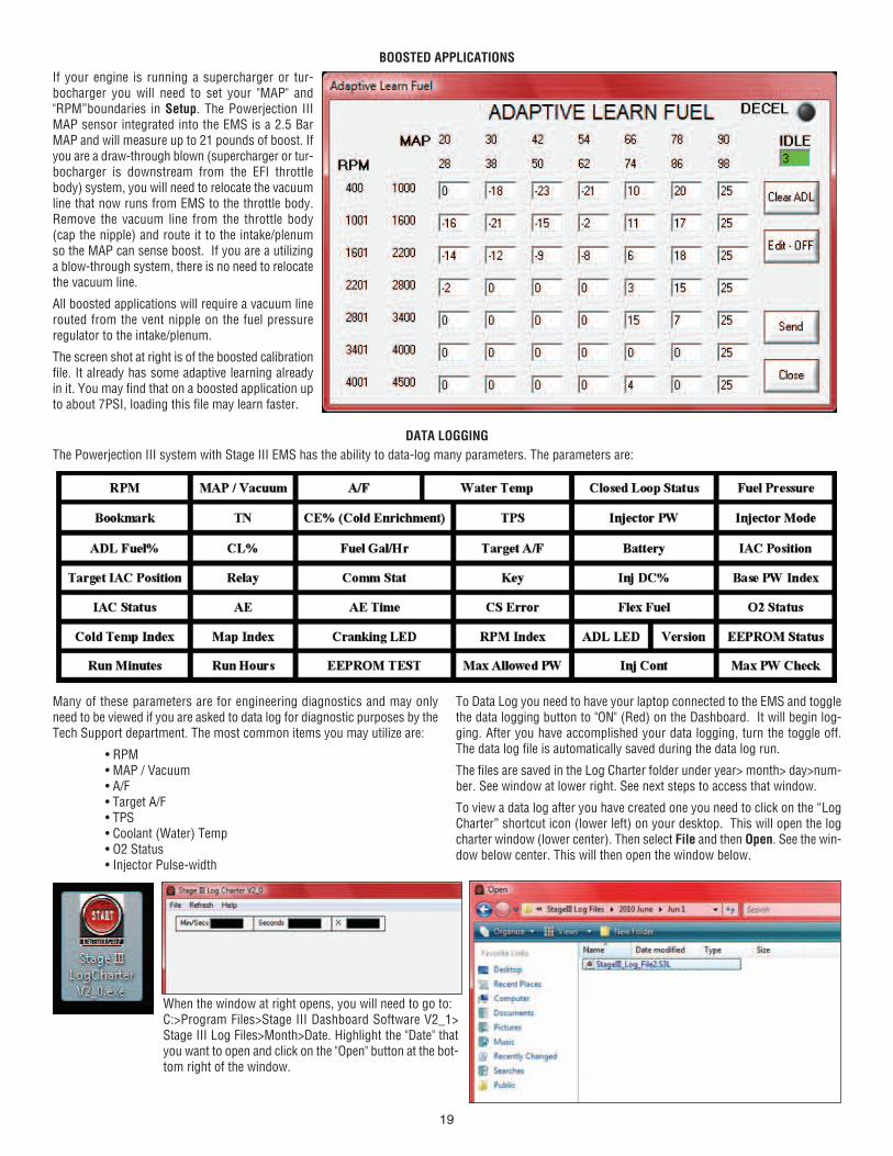
If your engine is running a supercharger or tur-bocharger you will need to set your "MAP" and"RPM”boundaries in Setup. The Powerjection IIIMAP sensor integrated into the EMS is a 2.5 BarMAP and will measure up to 21 pounds of boost. Ifyou are a draw-through blown (supercharger or tur-bocharger is downstream from the EFI throttlebody) system, you will need to relocate the vacuumline that now runs from EMS to the throttle body.Remove the vacuum line from the throttle body(cap the nipple) and route it to the intake/plenumso the MAP can sense boost. If you are a utilizinga blow-through system, there is no need to relocatethe vacuum line.
All boosted applications will require a vacuum linerouted from the vent nipple on the fuel pressureregulator to the intake/plenum.
The screen shot at right is of the boosted calibrationfile. It already has some adaptive learning alreadyin it. You may find that on a boosted application upto about 7PSI, loading this file may learn faster.
The Powerjection III system with Stage III EMS has the ability to data-log many parameters. The parameters are:
Many of these parameters are for engineering diagnostics and may onlyneed to be viewed if you are asked to data log for diagnostic purposes by theTech Support department. The most common items you may utilize are:
• RPM• MAP / Vacuum• A/F• Target A/F• TPS• Coolant (Water) Temp• O2 Status• Injector Pulse-width
To Data Log you need to have your laptop connected to the EMS and togglethe data logging button to "ON" (Red) on the Dashboard. It will begin log-ging. After you have accomplished your data logging, turn the toggle off.The data log file is automatically saved during the data log run.
The files are saved in the Log Charter folder under year> month> day>num-ber. See window at lower right. See next steps to access that window.
To view a data log after you have created one you need to click on the “LogCharter” shortcut icon (lower left) on your desktop. This will open the logcharter window (lower center). Then select File and then Open. See the win-dow below center. This will then open the window below.
When the window at right opens, you will need to go to:C:>Program Files>Stage III Dashboard Software V2_1>Stage III Log Files>Month>Date. Highlight the "Date" thatyou want to open and click on the "Open" button at the bot-tom right of the window.
19

Then the file(s) for the day will display. If more than one data log file wascreated the same day, each of the created logs will be numbered numericallyin the order the log was created. See below. Next highlight the particular file
you wish to view and click the "Open" button. You will see the window shownat below. This is the the Parameter Selection window. Select the parametersyou wish to view.
As you click on each parameter that you want to view, it will move to the left(see arrows at right) under the "Chart" column. After you have made yourchoices of the parameters you want to view (choose as many as you want)then click on the "OK" button in the lower right of the window. The viewer willnow open. See below. In this sample the RPM, MAP, and A/F were selectedto view.
Each parameter has a vertical red cross hair that can be moved laterally bymoving your mouse. The "Y" value at the left of each window indicates thevalue at the cross hair.
Across the top are time tables. The value shown in the time tables representwhere the cross hair is in the log
2070020-INST - Rev. 06-01-10