Embed Size (px)
Citation preview

Powercode Documentation – Routed Network Tutorial
http://www.powercode.com
Powercode Routed Network Tutorial
The purpose of this document is to give a basic overview of the configuration needed in Powercode to
support a routed Layer3 network. For this document, the example router used will be a Mikrotik 450G
but this tutorial applies to any type of router.
Example Network
Here is an example network with two Routers and a Powercode BMU. For the purpose of this tutorial,
we are not running any routing protocol – the routers are simply using static routes to get back to the
BMU.
Powercode is going to give out the subnet 172.30.1.0/24 to devices on Router A and 172.30.2.0/24 to
devices on Router B. These subnets will be active on Ether2.
Router A Configuration Router A needs a basic configuration. Since it is at the end of a spoke and only has one neighbor, we
only need to have a default route to Router B. We will need to configure Ether5 with the correct IP
address, setup DHCP Relay so that DHCP requests are forwarded to the Powercode BMU and add a
default route.
This example configuration will be shown on a Mikrotik 450G running v4.11 of RouterOS but this
example can be applied to any type of router.
First, go into Powercode and add every IP address used on a router interface into Infrastructure. If the
IP addresses are not in Infrastructure, Powercode will not allow the BMU to communicate with that IP.
This is the biggest cause of ‘routing problems’ to the BMU. So, you will need to add 192.168.1.1,
192.168.1.2, 196.168.1.6, 172.30.1.1 and 172.30.2.1 to Infrastructure (see table below)

Powercode Documentation – Routed Network Tutorial
http://www.powercode.com
192.168.1.1 Router A Ether5
192.168.1.2 Router B Ether4
192.168.1.6 Router B Ether 5
172.30.1.1 Router A Ether 2 (customer interface)
172.30.2.1 Router B Ether 2 (customer interface)
First, configure Ether5 to have the IP address 192.168.1.1 with a subnet mask of 255.255.255.252 per
our diagram above.
Navigate to IP > Addresses

Powercode Documentation – Routed Network Tutorial
http://www.powercode.com
Press the Add button and enter 192.168.1.1/30 as the address. Set the interface to Ether5 and click OK.
We also need to add a subnet for our DHCP pool (which will be relayed to the BMU.) Click Add again and
enter the subnet for our DHCP pool – in this case, 172.30.1.0/24. Let’s apply it to Ether2. Make sure you
set the IP address to 172.30.1.1 for this subnet – we need to have a valid IP address on here for the
customers to use as their default gateway.

Powercode Documentation – Routed Network Tutorial
http://www.powercode.com
Now you should see the IP addresses listed in the Address List window.

Powercode Documentation – Routed Network Tutorial
http://www.powercode.com
Navigate to IP > Routes

Powercode Documentation – Routed Network Tutorial
http://www.powercode.com
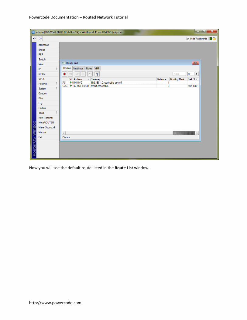
We are going to add a default route to 192.168.1.2, our directly connected router. Enter 0.0.0.0/0 in the
Dst. Address field and 192.168.1.2 in the Gateway field.
Powercode Documentation – Routed Network Tutorial
http://www.powercode.com
Now you will see the default route listed in the Route List window.
Powercode Documentation – Routed Network Tutorial
http://www.powercode.com
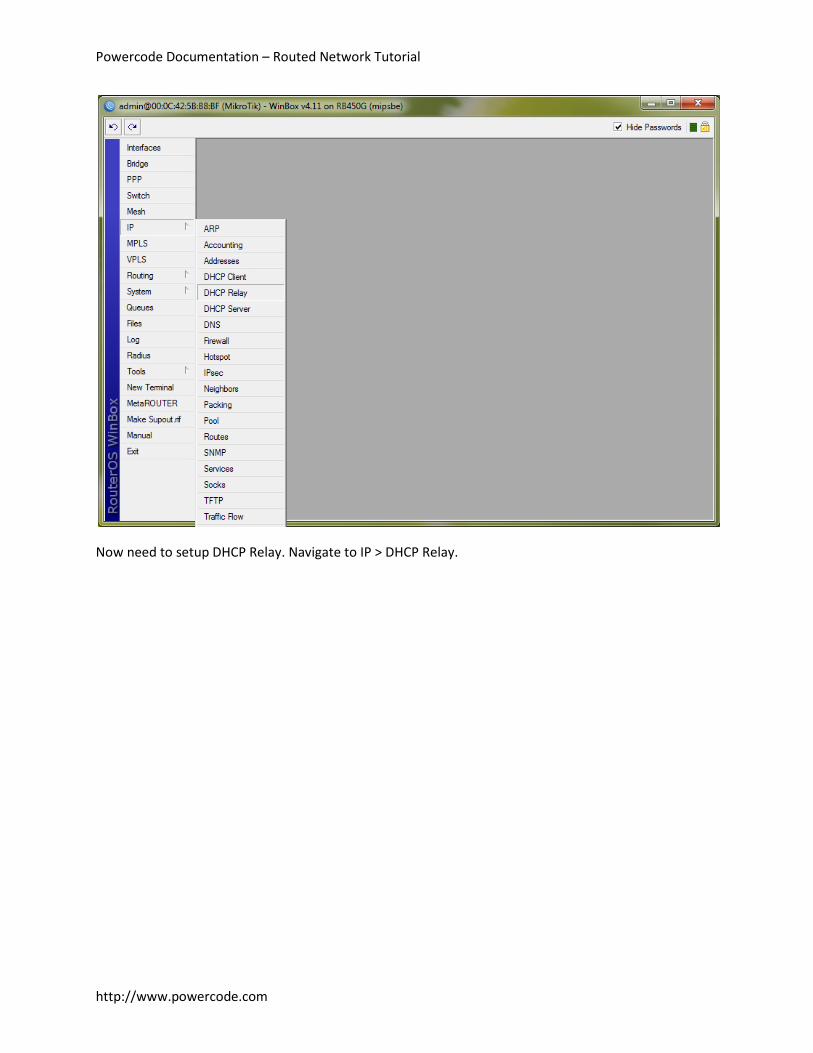
Now need to setup DHCP Relay. Navigate to IP > DHCP Relay.
Powercode Documentation – Routed Network Tutorial
http://www.powercode.com
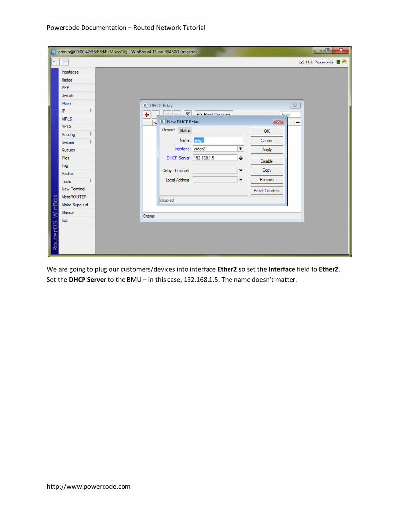
We are going to plug our customers/devices into interface Ether2 so set the Interface field to Ether2.
Set the DHCP Server to the BMU – in this case, 192.168.1.5. The name doesn’t matter.
Powercode Documentation – Routed Network Tutorial
http://www.powercode.com
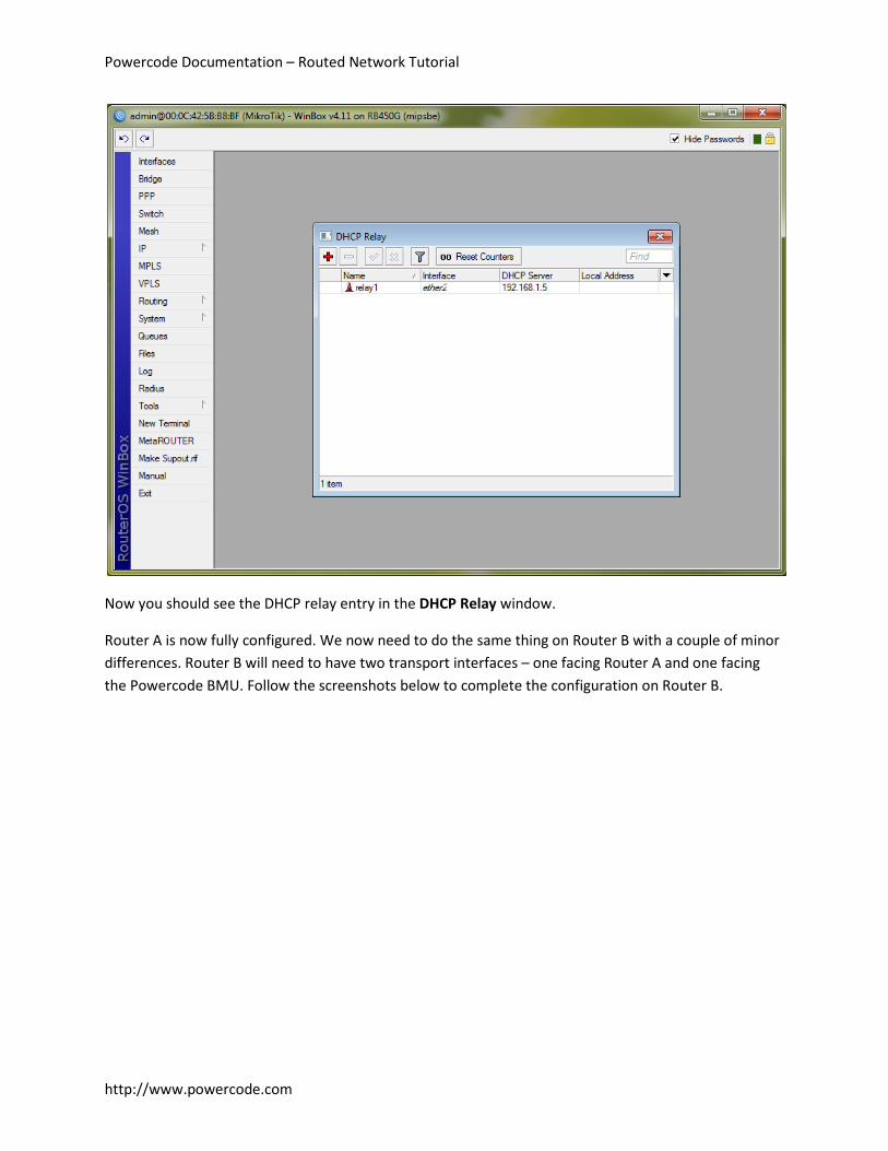
Now you should see the DHCP relay entry in the DHCP Relay window.
Router A is now fully configured. We now need to do the same thing on Router B with a couple of minor
differences. Router B will need to have two transport interfaces – one facing Router A and one facing
the Powercode BMU. Follow the screenshots below to complete the configuration on Router B.

Powercode Documentation – Routed Network Tutorial
http://www.powercode.com
Configure the IP addresses – notice we are using Ether2 again for the customer interface.

Powercode Documentation – Routed Network Tutorial
http://www.powercode.com
Add your default route and point it to the Powercode BMU (192.168.1.5)

Powercode Documentation – Routed Network Tutorial
http://www.powercode.com
Your DHCP Relay configuration should be the same as Router A.
Finally, we need to configure the BMU via Powercode to support these routers.

Powercode Documentation – Routed Network Tutorial
http://www.powercode.com
First, let’s configure our eth1 interface that is facing Router B. The Type of Subnet is Local since this is a
local interface on the BMU. Set the IP Address to 192.168.1.5 and the Subnet Mask to 255.255.255.252
(/30).
Set the Interface to eth1 and select Use NAT for Routing if you are using private IP addresses. Enter
some DHCP information and click Submit.
Now the BMU will be able to communicate with Router B (as they are directly connected) but it will not
know about the route to Router A since it is not directly connected. Due to this, we will need to create a
static route in Powercode.

Powercode Documentation – Routed Network Tutorial
http://www.powercode.com
Enter a descriptive name in the Name field (e.g. Static Route to Router A). Set the Type of Subnet to
Remote-Static. Set the IP Address to the device that will route packets destined for our target – in this
case, Router B. Set the Subnet Mask to the mask of the subnet for the static route we are entering and
set the Network IP Address to the network IP for the static route.
For example, in this case we need to get to 192.168.1.1. The subnet for this IP is 192.168.1.0/30. Our
next hop for this route is Router B, which is 192.168.1.6. So our IP Address will be 192.168.1.6. Our
Subnet Mask will be 255.255.255.252 (/30). Our Network IP Address will be 192.168.1.0.
Set the rest of the information appropriately (Interface, Use NAT for Routing and DHCP Settings) and
then click Submit.
After a rebuilt, the BMU should be able to now ping 192.168.1.1 and Router A should be able to ping
192.168.1.5.

Powercode Documentation – Routed Network Tutorial
http://www.powercode.com
Now we need to create the DHCP pool for the customer space. Let’s setup the DHCP pool for Router B
which is 172.30.2.0/24.
We will mimic a lot of our previous settings. Set the Type of Subnet to Remote-Static. Set the IP Address
to the next hop to reach this subnet, in this case, 192.168.1.6. Set the Subnet Mask to the mask for the
subnet, in this case, 255.255.255.0 (/30). Set the Network IP Address to the first IP in the subnet, in this
case, 172.30.2.0. Set the Interface to the appropriate interface, in this case, eth1. Since this is a private
IP, we are going to select Yes in Use NAT for Routing. Enter the DHCP Settings properly.
Since the customer facing interface on Router B is 172.30.2.1 we are going to set Gateway to
172.30.2.1. Enter your DNS servers. Click Submit.
Lastly, we are going to create our DHCP range.

Powercode Documentation – Routed Network Tutorial
http://www.powercode.com
Select the appropriate subnet from the drop down box, in this case, DHCP Pool for Router B. Enter a
descriptive name for this DHCP range. The First IP Address is the first IP you want to give out in this
range. For this example, we will use 172.30.2.2. We cannot use 172.30.2.1 as it is the IP of the Ether2
interface on Router B. Enter the Last IP Address you want to use – the last usable IP in our subnet is
172.30.2.254. Set the type to Static. Click Submit.
Now rebuilt the BMU. After the rebuilt is finished, if you plug a device into Ether2 on Router B, add the
MAC address of the device to a customer account in Powercode and assign it to this DHCP pool, Router
B will relay the DHCP request over to the Powercode BMU which will assign it an IP address.
Notes This approach is not terribly scalable. If you plan to have multiple routers in the network, it makes more
sense to use a routing protocol such as OSPF – however, this is fairly complex and outside the scope of

Powercode Documentation – Routed Network Tutorial
http://www.powercode.com
this document. This configuration is more suited to a small number of routers with no more than 2 hops
from the BMU to any other router in the network.
Useful Tools
Boson Subnet Calculator - http://www.boson.com/FreeUtilities.html
WinMTR - http://winmtr.sourceforge.net/
The Dude Network Monitor - http://www.mikrotik.com/thedude.php