Embed Size (px)
Citation preview
VMware Virtual SAN Routed Network Deployments with Brocade Deployments
T E C H N I C A L W H I T E P A P E R U P D A T E – N O V E M B E R V E R S I O N 1 . 1
T E C H N I C A L W H I T E P A P E R / 1
VMware Virtual SAN Routed Network Deployments with Brocade
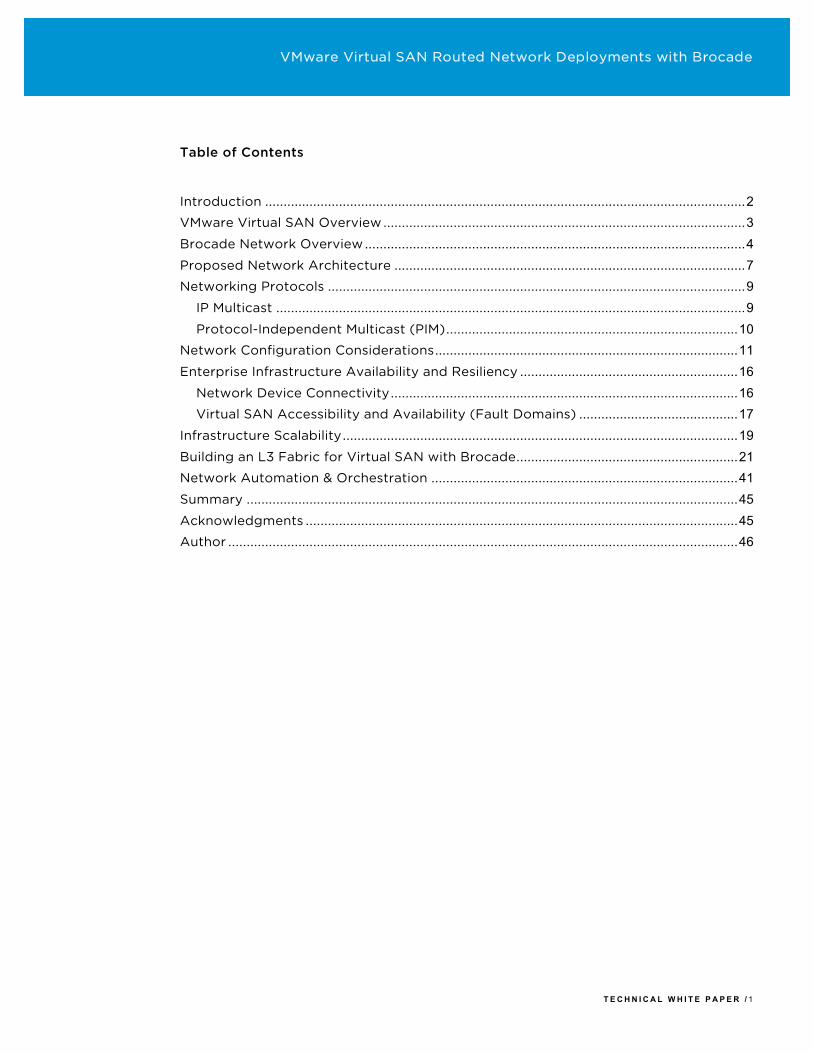
Table of Contents
Introduction .................................................................................................................................. 2VMware Virtual SAN Overview .................................................................................................. 3Brocade Network Overview ....................................................................................................... 4Proposed Network Architecture ............................................................................................... 7Networking Protocols ................................................................................................................. 9
IP Multicast ............................................................................................................................... 9Protocol-Independent Multicast (PIM) ............................................................................... 10
Network Configuration Considerations .................................................................................. 11Enterprise Infrastructure Availability and Resiliency ........................................................... 16
Network Device Connectivity .............................................................................................. 16Virtual SAN Accessibility and Availability (Fault Domains) ........................................... 17
Infrastructure Scalability ........................................................................................................... 19Building an L3 Fabric for Virtual SAN with Brocade ............................................................ 21Network Automation & Orchestration ................................................................................... 41Summary ..................................................................................................................................... 45Acknowledgments ..................................................................................................................... 45Author .......................................................................................................................................... 46
VMware Virtual SAN Routed Network Deployments with Brocade
Introduction The focus of this paper is to help virtualization, network, and storage implementation engineers, administrators, and architects simplify the deployment of a robust, high performant, scalable, and highly available, hyper-converged infrastructure (HCI) with VMware Virtual SAN and Brocade networking devices across routed network topologies.
VMware Virtual SAN Routed Network Deployments with Brocade
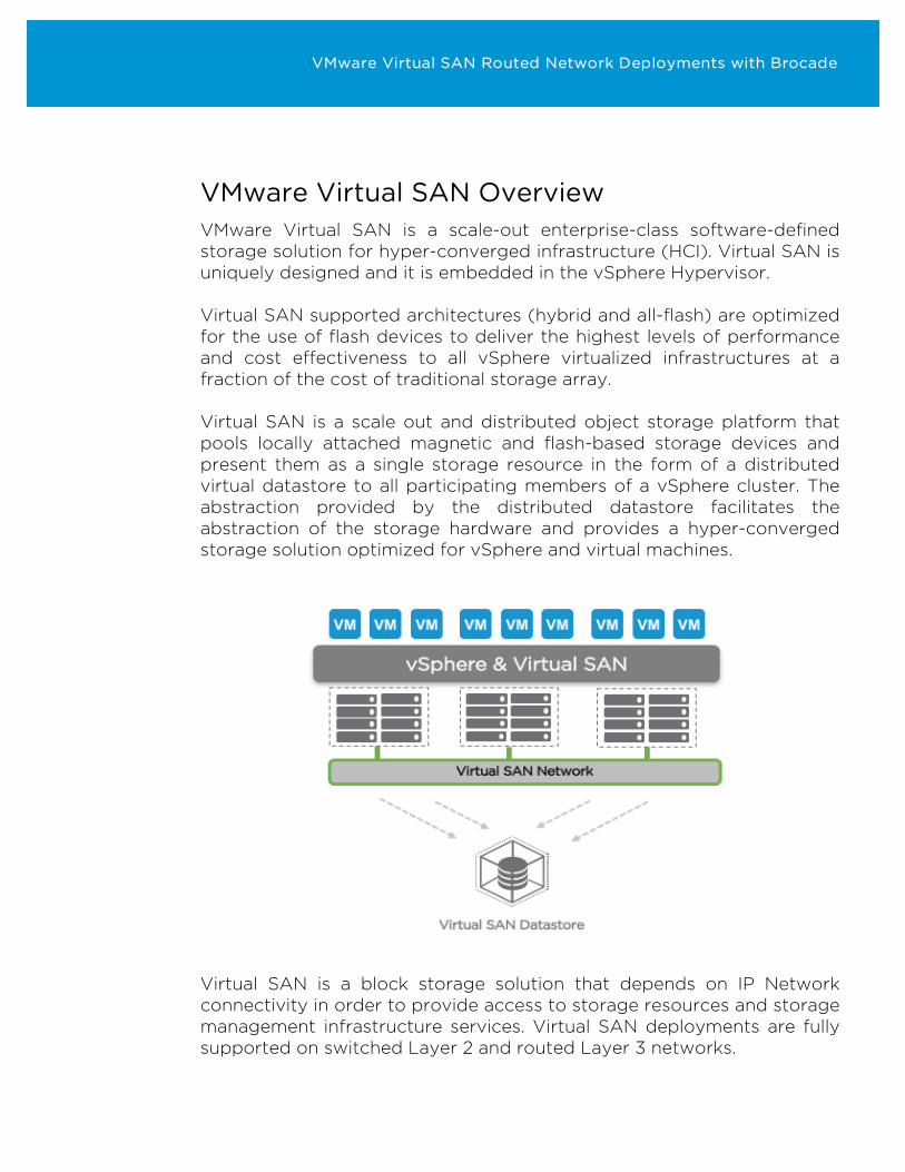
VMware Virtual SAN Overview VMware Virtual SAN is a scale-out enterprise-class software-defined storage solution for hyper-converged infrastructure (HCI). Virtual SAN is uniquely designed and it is embedded in the vSphere Hypervisor. Virtual SAN supported architectures (hybrid and all-flash) are optimized for the use of flash devices to deliver the highest levels of performance and cost effectiveness to all vSphere virtualized infrastructures at a fraction of the cost of traditional storage array. Virtual SAN is a scale out and distributed object storage platform that pools locally attached magnetic and flash-based storage devices and present them as a single storage resource in the form of a distributed virtual datastore to all participating members of a vSphere cluster. The abstraction provided by the distributed datastore facilitates the abstraction of the storage hardware and provides a hyper-converged storage solution optimized for vSphere and virtual machines.
Virtual SAN is a block storage solution that depends on IP Network connectivity in order to provide access to storage resources and storage management infrastructure services. Virtual SAN deployments are fully supported on switched Layer 2 and routed Layer 3 networks.
VMware Virtual SAN Routed Network Deployments with Brocade
Built on a distributed architecture where VMware vSphere hosts act as both storage resources and consumers, Virtual SAN requires that all participating hosts in a Virtual SAN cluster can communicate with each other and are members of the same VMware vSphere cluster. A key advantage of using networks based on the IP protocol for Virtual SAN is the increased flexibility and scalability compared to other storage area network (SAN) technologies. Many of these were designed with a local area scope in mind, whereas IP has been designed from the ground up to support large (Internet) scale by interconnecting multiple separate network segments. Virtual SAN has been architected to use this when deployed on a Layer 3 (L3) IP network where multiple individual Ethernet network segments are interconnected using IP routing. This approach eliminates any scalability limitations of a Layer 2 (L2) Ethernet network architecture, and allows for greater flexibility when physically placing hosts participating in Virtual SAN clusters. No longer is it needed to reserve rack space and contiguous floor tiles in the data center for storage expansions. Together with Virtual SAN Fault Domains a Virtual SAN cluster can be spread over many data center racks with redundant copies of data stored in different racks, hereby increasing resiliency.
Brocade Network Overview A pioneer of mission-critical SAN fabrics and storage networking, Brocade has evolved into a leading provider of network technology for data centers of all types and sizes. The Brocade VDX family of Ethernet switches has been designed to meet the requirements of modern applications and have a proven track record in deployments with stringent requirements. As the function of Virtual SAN is highly dependent on the underlying IP network, Brocade VDX switches are a natural fit for supporting VMware Virtual SAN. Brocade VDX switches are available in both fixed form factor and modular chassis configurations, all based on the same enterprise grade network operating system with built-in hardware redundancy and in-service software upgrades.
VMware Virtual SAN Routed Network Deployments with Brocade
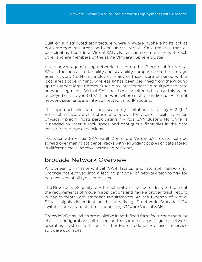
In this paper we’re going to focus on scale out architecture with the Brocade VDX fixed form factor switches, specifically: Brocade VDX6740
- 48x 10Gbit/s Ethernet SFP+ ports and 4x 40Gbit/s Ethernet QSFP ports
- Line rate switching and routing on all ports - 850ns any-port-to-any-port latency with cut through switching - 1U form factor, dual power supplies, and front-to-back or back-to-
front airflow - 110W maximum power consumption
Figure 1: Brocade VDX6740
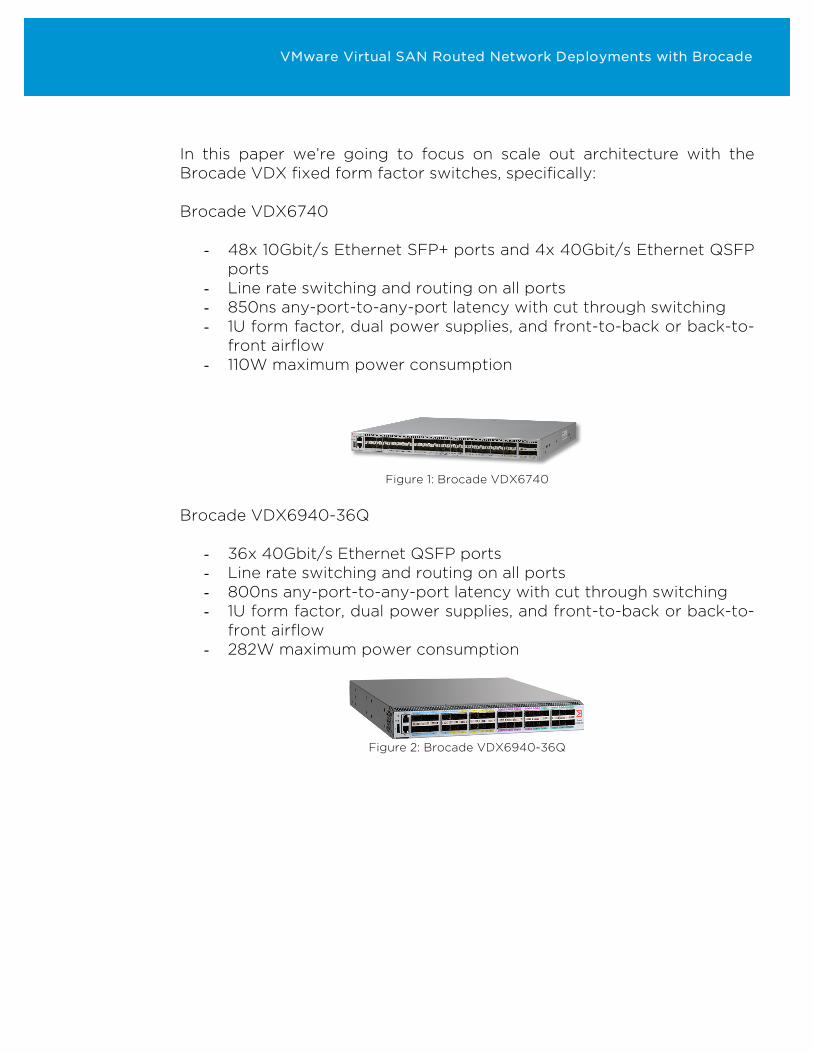
Brocade VDX6940-36Q
- 36x 40Gbit/s Ethernet QSFP ports - Line rate switching and routing on all ports - 800ns any-port-to-any-port latency with cut through switching - 1U form factor, dual power supplies, and front-to-back or back-to-
front airflow - 282W maximum power consumption
Figure 2: Brocade VDX6940-36Q
VMware Virtual SAN Routed Network Deployments with Brocade
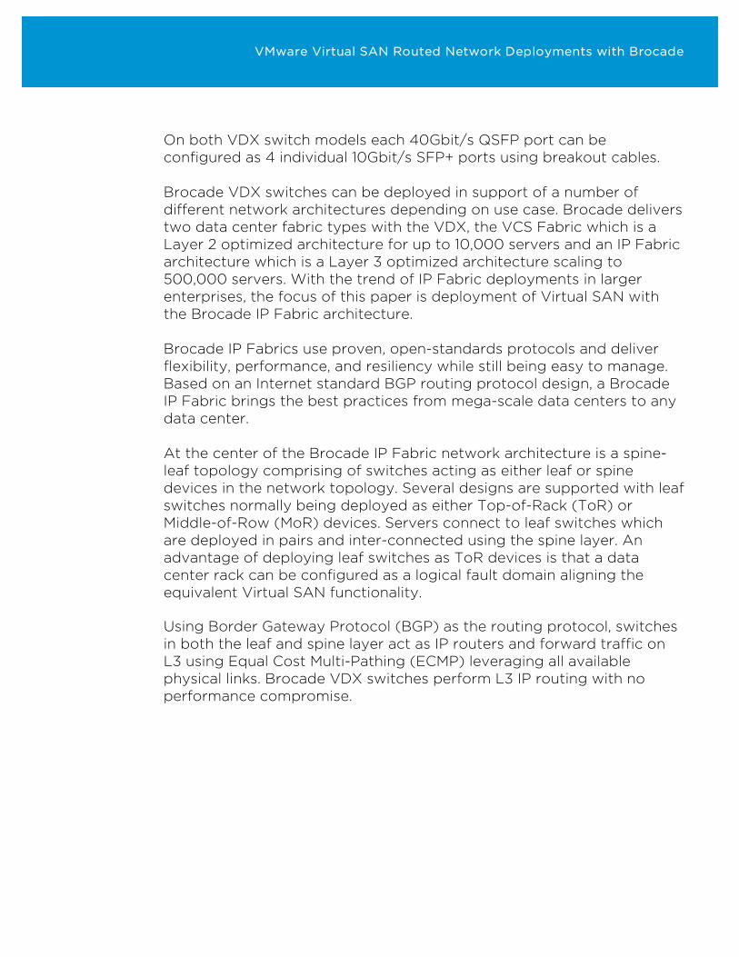
On both VDX switch models each 40Gbit/s QSFP port can be configured as 4 individual 10Gbit/s SFP+ ports using breakout cables. Brocade VDX switches can be deployed in support of a number of different network architectures depending on use case. Brocade delivers two data center fabric types with the VDX, the VCS Fabric which is a Layer 2 optimized architecture for up to 10,000 servers and an IP Fabric architecture which is a Layer 3 optimized architecture scaling to 500,000 servers. With the trend of IP Fabric deployments in larger enterprises, the focus of this paper is deployment of Virtual SAN with the Brocade IP Fabric architecture. Brocade IP Fabrics use proven, open-standards protocols and deliver flexibility, performance, and resiliency while still being easy to manage. Based on an Internet standard BGP routing protocol design, a Brocade IP Fabric brings the best practices from mega-scale data centers to any data center. At the center of the Brocade IP Fabric network architecture is a spine-leaf topology comprising of switches acting as either leaf or spine devices in the network topology. Several designs are supported with leaf switches normally being deployed as either Top-of-Rack (ToR) or Middle-of-Row (MoR) devices. Servers connect to leaf switches which are deployed in pairs and inter-connected using the spine layer. An advantage of deploying leaf switches as ToR devices is that a data center rack can be configured as a logical fault domain aligning the equivalent Virtual SAN functionality. Using Border Gateway Protocol (BGP) as the routing protocol, switches in both the leaf and spine layer act as IP routers and forward traffic on L3 using Equal Cost Multi-Pathing (ECMP) leveraging all available physical links. Brocade VDX switches perform L3 IP routing with no performance compromise.
VMware Virtual SAN Routed Network Deployments with Brocade
…
…
WANInternetWANInternet
EdgeLeaf
RackswithVirtualSANhostsRackswithVirtualSANhosts
Leaf(ToR)
Spine
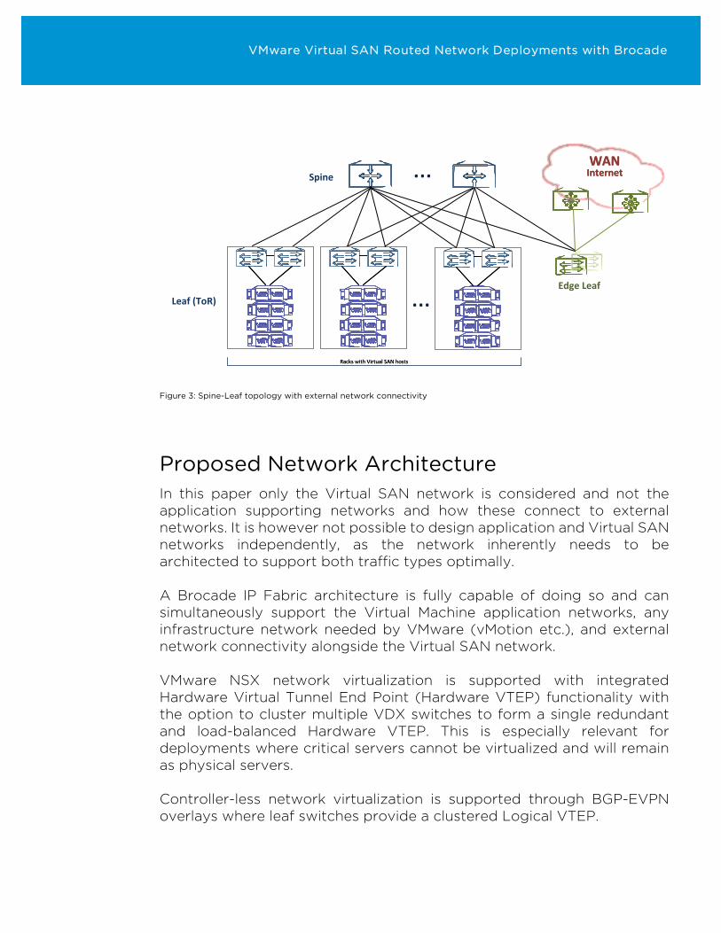
Figure 3: Spine-Leaf topology with external network connectivity
Proposed Network Architecture In this paper only the Virtual SAN network is considered and not the application supporting networks and how these connect to external networks. It is however not possible to design application and Virtual SAN networks independently, as the network inherently needs to be architected to support both traffic types optimally. A Brocade IP Fabric architecture is fully capable of doing so and can simultaneously support the Virtual Machine application networks, any infrastructure network needed by VMware (vMotion etc.), and external network connectivity alongside the Virtual SAN network. VMware NSX network virtualization is supported with integrated Hardware Virtual Tunnel End Point (Hardware VTEP) functionality with the option to cluster multiple VDX switches to form a single redundant and load-balanced Hardware VTEP. This is especially relevant for deployments where critical servers cannot be virtualized and will remain as physical servers. Controller-less network virtualization is supported through BGP-EVPN overlays where leaf switches provide a clustered Logical VTEP.
VMware Virtual SAN Routed Network Deployments with Brocade
Network virtualization is especially relevant for any networks requiring L2 transparency, like vMotion. The Brocade IP Fabric spine-leaf topology can be expanded with more layers for even greater scalability by deploying an additional switch layer (super-spine) on top of the spine layer. When evaluating network designs for Virtual SAN it is important to remember that the requirements for any network supporting storage traffic applies here as well. They include:
- Predictable data path through network - Low latency and high bandwidth - Redundant and resilient - In service upgradable - Scalable without disruption
In addition, it should be noted that since Virtual SAN is based on a distributed architecture with hosts being both storage initiators and targets, the amount of east-west traffic between hosts in the network is much higher than in traditional SANs where many hosts (initiators) access the same target, causing a more north-south bound traffic flow. The spine-leaf topology of the Brocade IP Fabric features a predictable east-west traffic path between all hosts (leaf-spine-leaf) with a low hop count. Hosts can be connected to dual leaf switches, which again are inter-connected through multiple links to dual spine switches, hereby achieving full redundancy. When additional bandwidth is needed, additional links between switches can be non-disruptively added and utilized. These properties are all highly desirable in a network supporting Virtual SAN traffic and makes the Brocade IP Fabric architecture a perfect fit.
VMware Virtual SAN Routed Network Deployments with Brocade
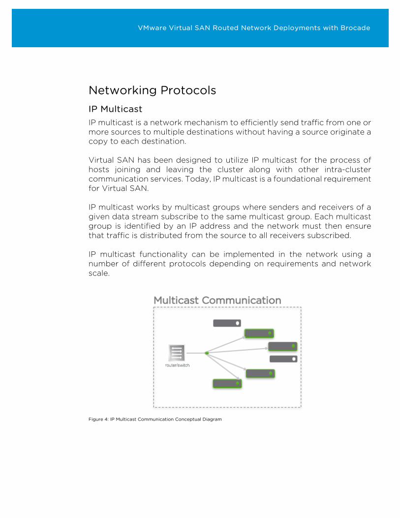
Networking Protocols IP Multicast IP multicast is a network mechanism to efficiently send traffic from one or more sources to multiple destinations without having a source originate a copy to each destination. Virtual SAN has been designed to utilize IP multicast for the process of hosts joining and leaving the cluster along with other intra-cluster communication services. Today, IP multicast is a foundational requirement for Virtual SAN. IP multicast works by multicast groups where senders and receivers of a given data stream subscribe to the same multicast group. Each multicast group is identified by an IP address and the network must then ensure that traffic is distributed from the source to all receivers subscribed. IP multicast functionality can be implemented in the network using a number of different protocols depending on requirements and network scale.
Figure 4: IP Multicast Communication Conceptual Diagram
VMware Virtual SAN Routed Network Deployments with Brocade
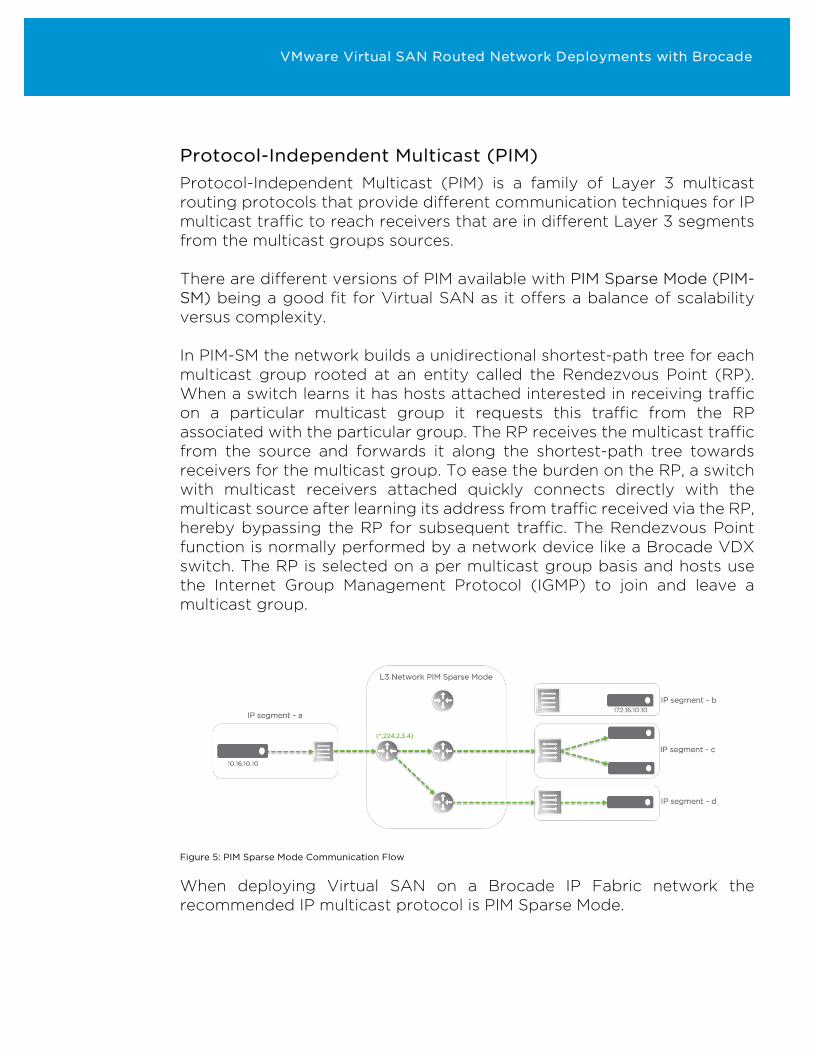
Protocol-Independent Multicast (PIM) Protocol-Independent Multicast (PIM) is a family of Layer 3 multicast routing protocols that provide different communication techniques for IP multicast traffic to reach receivers that are in different Layer 3 segments from the multicast groups sources. There are different versions of PIM available with PIM Sparse Mode (PIM-SM) being a good fit for Virtual SAN as it offers a balance of scalability versus complexity. In PIM-SM the network builds a unidirectional shortest-path tree for each multicast group rooted at an entity called the Rendezvous Point (RP). When a switch learns it has hosts attached interested in receiving traffic on a particular multicast group it requests this traffic from the RP associated with the particular group. The RP receives the multicast traffic from the source and forwards it along the shortest-path tree towards receivers for the multicast group. To ease the burden on the RP, a switch with multicast receivers attached quickly connects directly with the multicast source after learning its address from traffic received via the RP, hereby bypassing the RP for subsequent traffic. The Rendezvous Point function is normally performed by a network device like a Brocade VDX switch. The RP is selected on a per multicast group basis and hosts use the Internet Group Management Protocol (IGMP) to join and leave a multicast group.
Figure 5: PIM Sparse Mode Communication Flow
When deploying Virtual SAN on a Brocade IP Fabric network the recommended IP multicast protocol is PIM Sparse Mode.
VMware Virtual SAN Routed Network Deployments with Brocade
Network Configuration Considerations In a Brocade IP Fabric design for Virtual SAN it is recommended that the PIM-SM Rendezvous Point is hosted by switches in the spine layer. To achieve RP redundancy, the PIM Boot Strap Router (BSR) mechanism is used to elect the RP from a list of candidates hosted by the spine switches. In the case the selected RP candidate fails, BSR will select a new RP is and multicast operations will continue. BSR also has an election mechanism to make sure a new BSR becomes active in case of a failure. It is recommended that spine switches used as RP candidates are also configured as BSR candidates. To ensure Virtual SAN traffic is prioritized should a network congestion situation occur it is recommended to implement the Auto QoS feature on the Brocade IP Fabric network. Auto QoS provides a simple to configure Quality of Service policy to ensure IP storage traffic receives priority and is well-aligned with the needs of Virtual SAN traffic. To limit the potential effects of TCP Incast (many flows towards one switch port) the dynamic switch port buffers should be set to recommended values for IP storage. All switch port buffers on Brocade VDX switches are implemented on-chip and cut-through switching is used between ports running at same speed.
Host Connectivity
Virtual SAN traffic is transported over VMkernel network interfaces (vmk) connected to virtual switches which connect to the physical network through physical network interface cards (NIC or vmnic).
With dual host facing leaf switches available in the IP Fabric design each host participating in a Virtual SAN cluster should be equipped with a minimum of 2 NICs supporting Virtual SAN traffic.
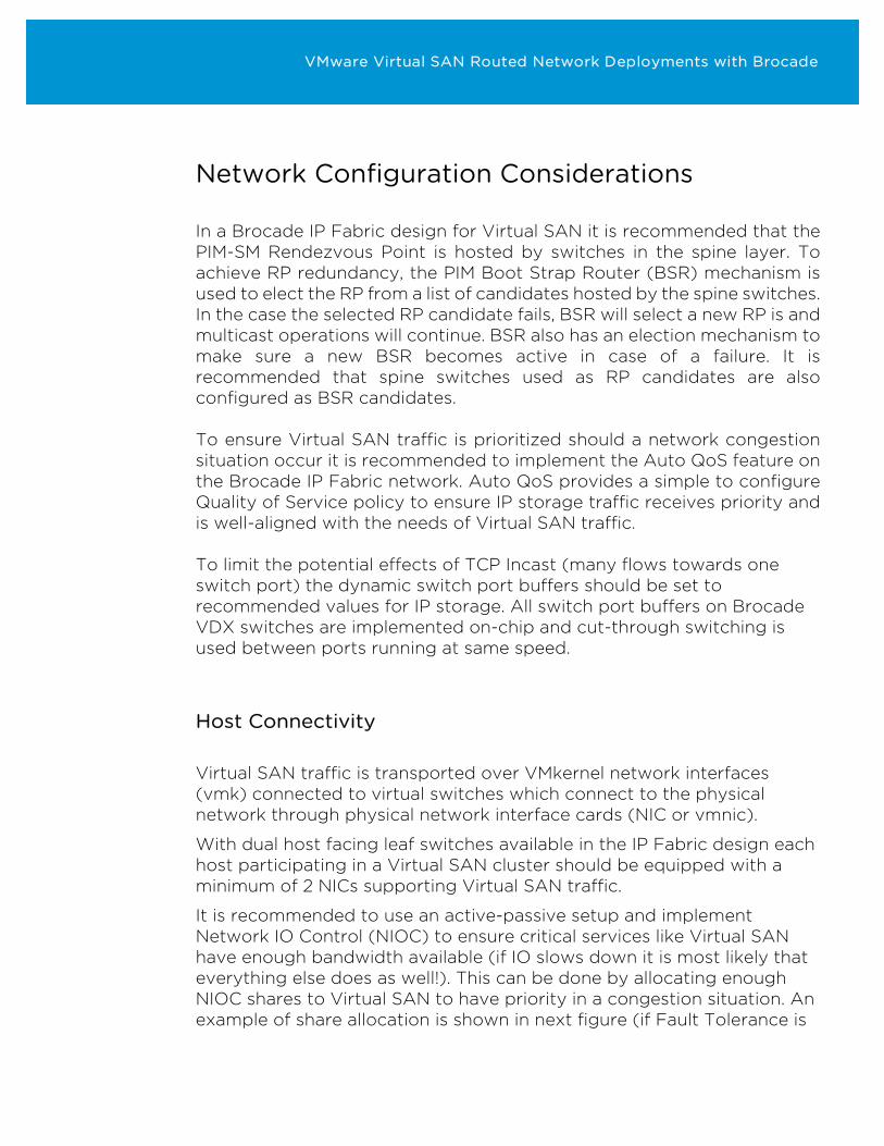
It is recommended to use an active-passive setup and implement Network IO Control (NIOC) to ensure critical services like Virtual SAN have enough bandwidth available (if IO slows down it is most likely that everything else does as well!). This can be done by allocating enough NIOC shares to Virtual SAN to have priority in a congestion situation. An example of share allocation is shown in next figure (if Fault Tolerance is
VMware Virtual SAN Routed Network Deployments with Brocade
implemented this should also be considered in the share allocation).
Figure 6: Host with 2 NICs with proposed NOIC shares and Explicit Failover setup. Solid lines are active uplinks, dotted are standby.
A way to load multiple physical adapters in this setup is to set an explicit failover order with different active uplinks among traffic types.
For the virtual switch it is recommended to implement the VMware vSphere Distributed Switch (vDS) and all Virtual SAN editions include license for this. The vDS facilitates large-scale deployments with advantages around management, advanced network features, and scalability that are all conducive to the benefits and values of Virtual SAN.
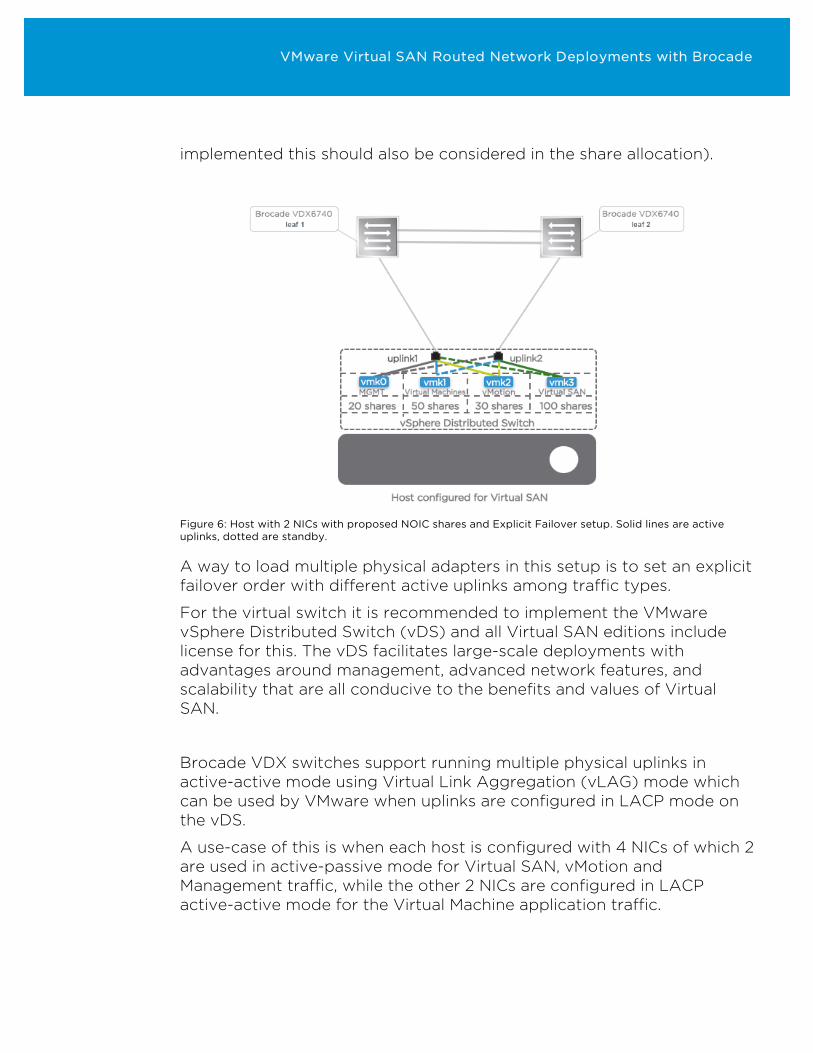
Brocade VDX switches support running multiple physical uplinks in active-active mode using Virtual Link Aggregation (vLAG) mode which can be used by VMware when uplinks are configured in LACP mode on the vDS.
A use-case of this is when each host is configured with 4 NICs of which 2 are used in active-passive mode for Virtual SAN, vMotion and Management traffic, while the other 2 NICs are configured in LACP active-active mode for the Virtual Machine application traffic.
VMware Virtual SAN Routed Network Deployments with Brocade
Figure 7: Host with 4 NICs and vLAG configured
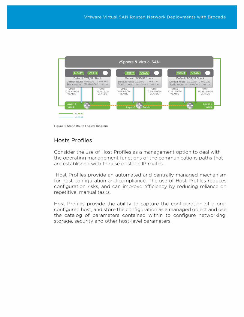
Host Static IP Routes The use of static routes is required by traffic services for which vSphere does not provide a non-Default TCP/IP stack. In the VMware recommended deployment scenario where the Management and Virtual SAN traffic services are configured to use different Layer 3 network segments, they will share the Default TCP/IP Stack but be configured in different Layer 2 domains. The default route for the Default TCP/IP Stack should remain with the Management VMkernel network interface. Static routes will be added for the Virtual SAN traffic to egress of the Virtual SAN VMkernel network interface. It is only necessary to configure a single static route per host for each remote Virtual SAN Layer 3 segment or a single summary static route if the Virtual SAN Layer 3 segment addressing plan allows it.
VMware Virtual SAN Routed Network Deployments with Brocade
Figure 8: Static Route Logical Diagram
Hosts Profiles
Consider the use of Host Profiles as a management option to deal with the operating management functions of the communications paths that are established with the use of static IP routes.
Host Profiles provide an automated and centrally managed mechanism for host configuration and compliance. The use of Host Profiles reduces configuration risks, and can improve efficiency by reducing reliance on repetitive, manual tasks. Host Profiles provide the ability to capture the configuration of a pre-configured host, and store the configuration as a managed object and use the catalog of parameters contained within to configure networking, storage, security and other host-level parameters.
VMware Virtual SAN Routed Network Deployments with Brocade
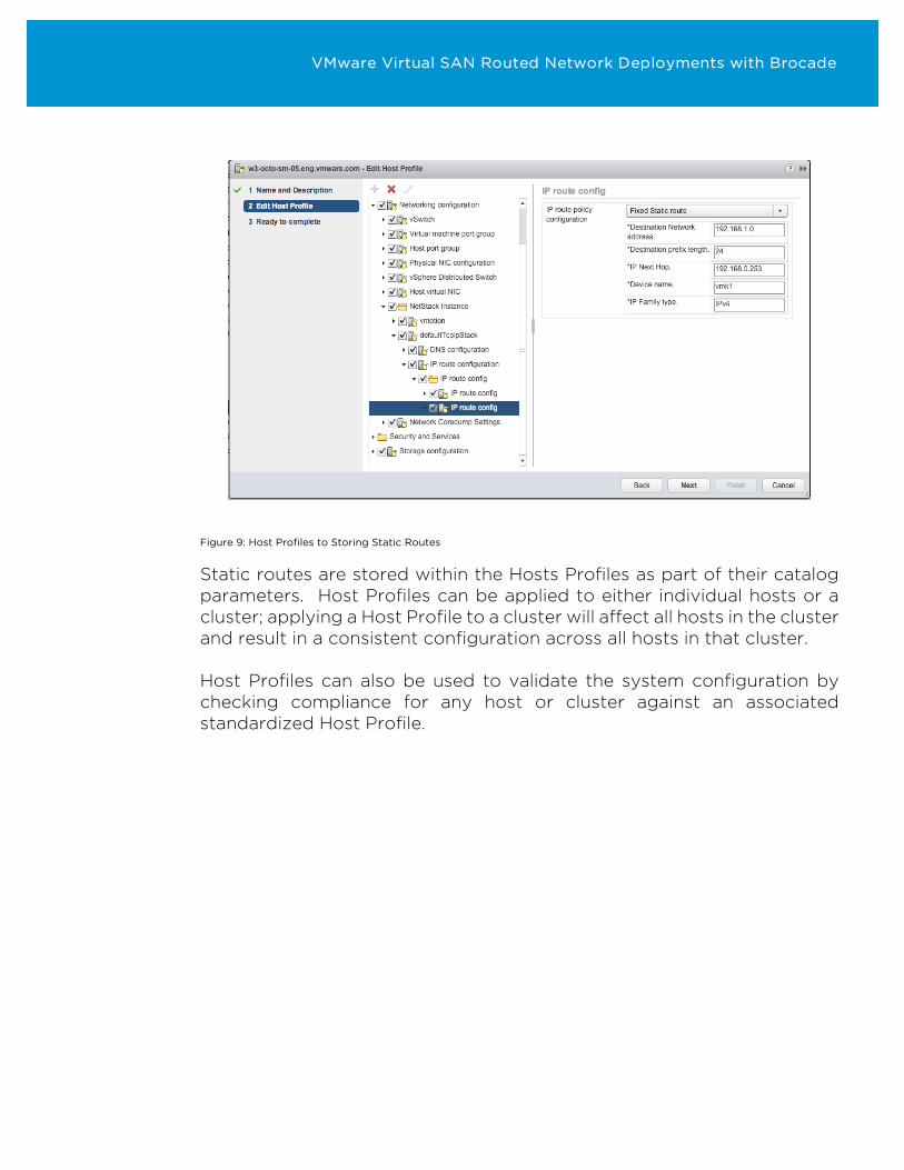
Figure 9: Host Profiles to Storing Static Routes
Static routes are stored within the Hosts Profiles as part of their catalog parameters. Host Profiles can be applied to either individual hosts or a cluster; applying a Host Profile to a cluster will affect all hosts in the cluster and result in a consistent configuration across all hosts in that cluster. Host Profiles can also be used to validate the system configuration by checking compliance for any host or cluster against an associated standardized Host Profile.
VMware Virtual SAN Routed Network Deployments with Brocade
Enterprise Infrastructure Availability and Resiliency Network Device Connectivity The Brocade IP Fabric architecture features inherent availability and resiliency along with active-active data paths throughout the network.
- Each host is connected to 2 leaf switches
- Each leaf switch is connected to 2 or more spine switches
- Each spine switch is connected to multiple super-spine switches (in the case of a multi-stage design)
Together with uncompromised performance, Reliability, Availability, and Serviceability (RAS) features of each Brocade VDX switch provide redundancy within each network element.
- Full support for in-service software upgrades.
- Power supplies are redundant and hot-swappable
- Transceivers are hot-pluggable
- More bandwidth between switches can be added and utilized non-disruptively
- Early failure detection software features with Monitoring and Alerting Policy Suite (MAPS) and Bidirectional Forwarding Detection (BFD)
VMware Virtual SAN Routed Network Deployments with Brocade
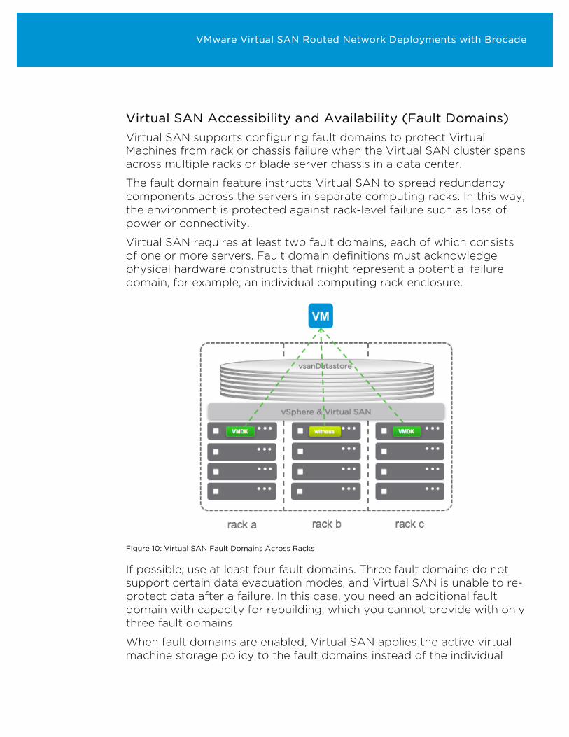
Virtual SAN Accessibility and Availability (Fault Domains) Virtual SAN supports configuring fault domains to protect Virtual Machines from rack or chassis failure when the Virtual SAN cluster spans across multiple racks or blade server chassis in a data center.
The fault domain feature instructs Virtual SAN to spread redundancy components across the servers in separate computing racks. In this way, the environment is protected against rack-level failure such as loss of power or connectivity.
Virtual SAN requires at least two fault domains, each of which consists of one or more servers. Fault domain definitions must acknowledge physical hardware constructs that might represent a potential failure domain, for example, an individual computing rack enclosure.
Figure 10: Virtual SAN Fault Domains Across Racks
If possible, use at least four fault domains. Three fault domains do not support certain data evacuation modes, and Virtual SAN is unable to re-protect data after a failure. In this case, you need an additional fault domain with capacity for rebuilding, which you cannot provide with only three fault domains.
When fault domains are enabled, Virtual SAN applies the active virtual machine storage policy to the fault domains instead of the individual
VMware Virtual SAN Routed Network Deployments with Brocade
hosts.
Calculate the number of fault domains in a cluster based on the Number of failures to tolerate attribute from the storage policies that you plan to assign to virtual machines.
• number of fault domains = 2 * number of failures to tolerate + 1
If a host is not a member of a fault domain, Virtual SAN interprets it as a stand-alone fault domain.
Consider a cluster that contains four server racks, each with two hosts. If the Number of failures to tolerate is set to one and fault domains are not enabled, Virtual SAN might store both replicas of an object with hosts in the same rack enclosure. In this way, applications might be exposed to a potential data loss on a rack-level failure.
When configuring hosts that could potentially fail together into separate fault domains, Virtual SAN ensures that each protection component (replicas and witnesses) is placed in a separate fault domain.
When adding hosts and capacity, the existing fault domain configuration can be used or new ones can define fault domains.
For balanced storage load and fault tolerance when using fault domains, consider the following guidelines:
• Provide enough fault domains to satisfy the Number of failures to tolerate that are configured in the storage policies.
• Define at least three fault domains. Define a minimum of four domains for best protection.
• Assign the same number of hosts to each fault domain. Use hosts that have uniform configurations and dedicate one fault domain of free capacity for rebuilding data after a failure, if possible.
VMware Virtual SAN Routed Network Deployments with Brocade
Infrastructure Scalability Brocade With a two-tier spine-leaf topology the IP Fabric easily scale to more than 850 hosts –(and even greater with a tree tier topology).
This is achieved using Brocade VDX6740 as ToR leaf switches and Brocade VDX6940-36Q as spine switches. With each leaf switch connecting to the spine layer using 4x 40Gbit/s ports a maximum scalability of 1,728 10Gbit/s server facing ports over 18 data center racks is achievable with an oversubscription of 3:1 between leaf and spine layer.
Assuming each host has 2 10Gbit/s NICs this allows for 864 hosts. Also assuming each rack with ToR leaf switches is configured as a Virtual SAN Fault Domain, and with the current version (6.2) of Virtual SAN supporting a maximum of 3 Failures to Tolerate, the most resilient architecture for a Virtual SAN cluster is obtained by spreading hosts over 7 racks (2x3+1). This allows for 3 racks to go offline simultaneously while still maintaining proper functioning of the Virtual SAN cluster!
If even greater scalability is desired the IP Fabric architecture can expand using modular switch models or by implementing super-spine switches. Using Brocade VDX6940-36Q to implement a super-spine layer the number of 10Gbit/s host ports increase to 31,104. An additional L2 switch aggregation layer below the leaf switches is another way to scale by expanding each L2 segment.
VMware Virtual SAN Routed Network Deployments with Brocade
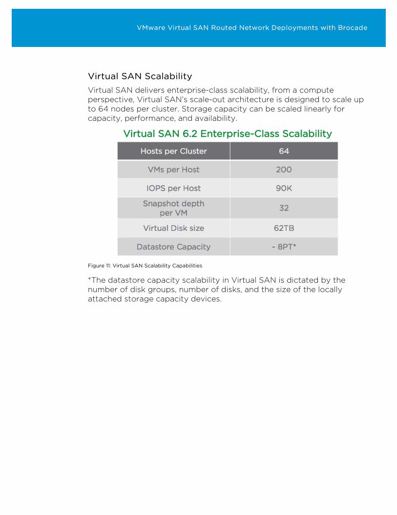
Virtual SAN Scalability Virtual SAN delivers enterprise-class scalability, from a compute perspective, Virtual SAN’s scale-out architecture is designed to scale up to 64 nodes per cluster. Storage capacity can be scaled linearly for capacity, performance, and availability.
Figure 11: Virtual SAN Scalability Capabilities
*The datastore capacity scalability in Virtual SAN is dictated by the number of disk groups, number of disks, and the size of the locally attached storage capacity devices.
VMware Virtual SAN Routed Network Deployments with Brocade
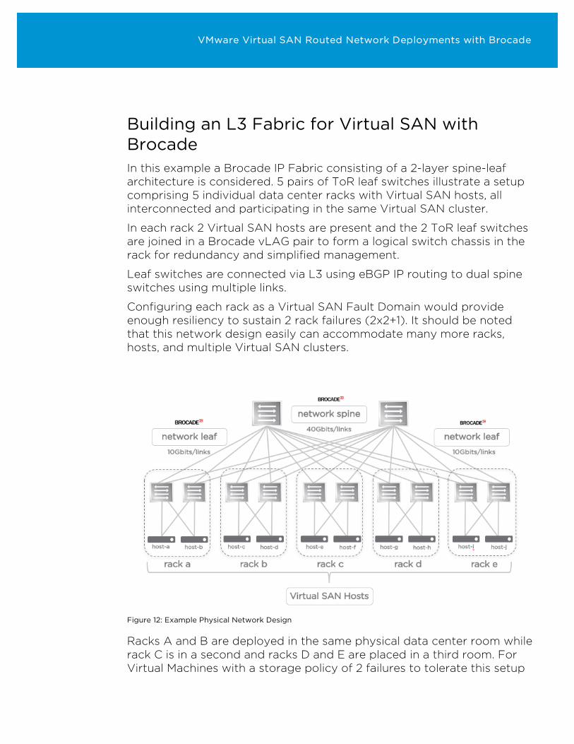
Building an L3 Fabric for Virtual SAN with Brocade In this example a Brocade IP Fabric consisting of a 2-layer spine-leaf architecture is considered. 5 pairs of ToR leaf switches illustrate a setup comprising 5 individual data center racks with Virtual SAN hosts, all interconnected and participating in the same Virtual SAN cluster.
In each rack 2 Virtual SAN hosts are present and the 2 ToR leaf switches are joined in a Brocade vLAG pair to form a logical switch chassis in the rack for redundancy and simplified management.
Leaf switches are connected via L3 using eBGP IP routing to dual spine switches using multiple links.
Configuring each rack as a Virtual SAN Fault Domain would provide enough resiliency to sustain 2 rack failures (2x2+1). It should be noted that this network design easily can accommodate many more racks, hosts, and multiple Virtual SAN clusters.
Figure 12: Example Physical Network Design
Racks A and B are deployed in the same physical data center room while rack C is in a second and racks D and E are placed in a third room. For Virtual Machines with a storage policy of 2 failures to tolerate this setup
VMware Virtual SAN Routed Network Deployments with Brocade
can allow any of the data center rooms to go offline without the Virtual Machine loosing storage access.
Switches in the leaf layer are Brocade VDX6740 while the spine switches are Brocade VDX6940-36Q. Configurations are based on all switches running Brocade Network Operating System (NOS) version 7.1.0.
Hosts and switches have already been cabled, links established, and management interfaces configured.
We start by configuring the L2 and L3 parts of the ToR leaf switch pair in each rack followed by the L3 configuration of the spine switches. In the end we configure Auto QoS and PIM-SM multicast.
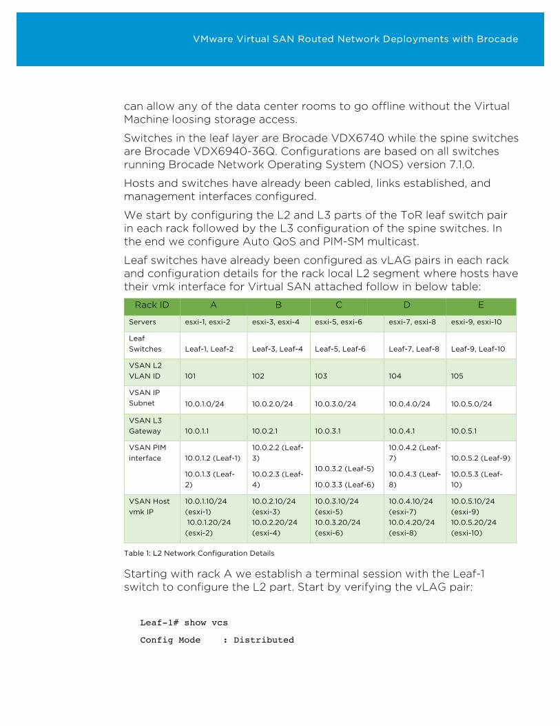
Leaf switches have already been configured as vLAG pairs in each rack and configuration details for the rack local L2 segment where hosts have their vmk interface for Virtual SAN attached follow in below table:
Rack ID A B C D E
Servers esxi-1, esxi-2 esxi-3, esxi-4 esxi-5, esxi-6 esxi-7, esxi-8 esxi-9, esxi-10
Leaf Switches Leaf-1, Leaf-2 Leaf-3, Leaf-4 Leaf-5, Leaf-6 Leaf-7, Leaf-8 Leaf-9, Leaf-10
VSAN L2 VLAN ID 101 102 103 104 105
VSAN IP Subnet 10.0.1.0/24 10.0.2.0/24 10.0.3.0/24 10.0.4.0/24 10.0.5.0/24
VSAN L3 Gateway 10.0.1.1 10.0.2.1 10.0.3.1 10.0.4.1 10.0.5.1
VSAN PIM interface 10.0.1.2 (Leaf-1)
10.0.1.3 (Leaf-2)
10.0.2.2 (Leaf-3)
10.0.2.3 (Leaf-4)
10.0.3.2 (Leaf-5)
10.0.3.3 (Leaf-6)
10.0.4.2 (Leaf-7)
10.0.4.3 (Leaf-8)
10.0.5.2 (Leaf-9)
10.0.5.3 (Leaf-10)
VSAN Host vmk IP
10.0.1.10/24 (esxi-1) 10.0.1.20/24 (esxi-2)
10.0.2.10/24 (esxi-3) 10.0.2.20/24 (esxi-4)
10.0.3.10/24 (esxi-5) 10.0.3.20/24 (esxi-6)
10.0.4.10/24 (esxi-7) 10.0.4.20/24 (esxi-8)
10.0.5.10/24 (esxi-9) 10.0.5.20/24 (esxi-10)
Table 1: L2 Network Configuration Details
Starting with rack A we establish a terminal session with the Leaf-1 switch to configure the L2 part. Start by verifying the vLAG pair:
Leaf-1# show vcs
Config Mode : Distributed
VMware Virtual SAN Routed Network Deployments with Brocade
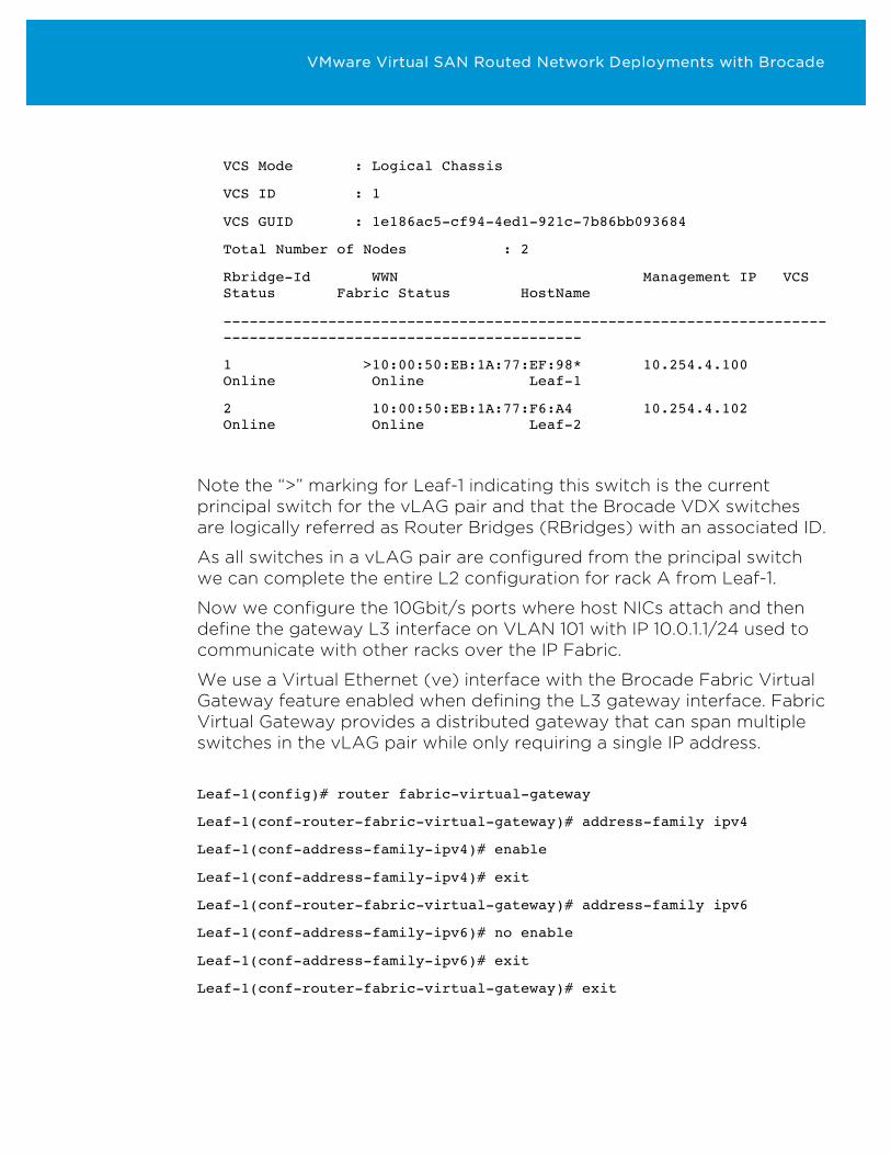
VCS Mode : Logical Chassis
VCS ID : 1
VCS GUID : 1e186ac5-cf94-4ed1-921c-7b86bb093684
Total Number of Nodes : 2
Rbridge-Id WWN Management IP VCS Status Fabric Status HostName
--------------------------------------------------------------------------------------------------------------
1 >10:00:50:EB:1A:77:EF:98* 10.254.4.100 Online Online Leaf-1
2 10:00:50:EB:1A:77:F6:A4 10.254.4.102 Online Online Leaf-2
Note the “>” marking for Leaf-1 indicating this switch is the current principal switch for the vLAG pair and that the Brocade VDX switches are logically referred as Router Bridges (RBridges) with an associated ID.
As all switches in a vLAG pair are configured from the principal switch we can complete the entire L2 configuration for rack A from Leaf-1.
Now we configure the 10Gbit/s ports where host NICs attach and then define the gateway L3 interface on VLAN 101 with IP 10.0.1.1/24 used to communicate with other racks over the IP Fabric.
We use a Virtual Ethernet (ve) interface with the Brocade Fabric Virtual Gateway feature enabled when defining the L3 gateway interface. Fabric Virtual Gateway provides a distributed gateway that can span multiple switches in the vLAG pair while only requiring a single IP address.
Leaf-1(config)# router fabric-virtual-gateway
Leaf-1(conf-router-fabric-virtual-gateway)# address-family ipv4
Leaf-1(conf-address-family-ipv4)# enable
Leaf-1(conf-address-family-ipv4)# exit
Leaf-1(conf-router-fabric-virtual-gateway)# address-family ipv6
Leaf-1(conf-address-family-ipv6)# no enable
Leaf-1(conf-address-family-ipv6)# exit
Leaf-1(conf-router-fabric-virtual-gateway)# exit
VMware Virtual SAN Routed Network Deployments with Brocade
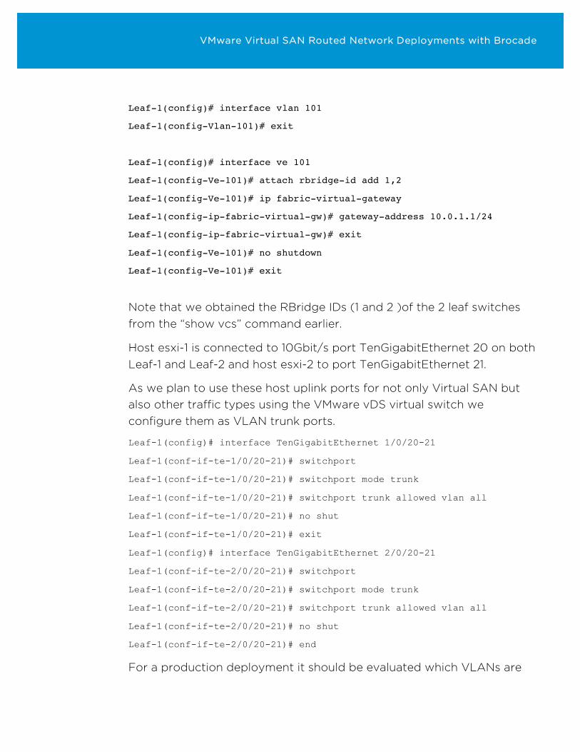
Leaf-1(config)# interface vlan 101
Leaf-1(config-Vlan-101)# exit
Leaf-1(config)# interface ve 101
Leaf-1(config-Ve-101)# attach rbridge-id add 1,2
Leaf-1(config-Ve-101)# ip fabric-virtual-gateway
Leaf-1(config-ip-fabric-virtual-gw)# gateway-address 10.0.1.1/24
Leaf-1(config-ip-fabric-virtual-gw)# exit
Leaf-1(config-Ve-101)# no shutdown
Leaf-1(config-Ve-101)# exit
Note that we obtained the RBridge IDs (1 and 2 )of the 2 leaf switches from the “show vcs” command earlier.
Host esxi-1 is connected to 10Gbit/s port TenGigabitEthernet 20 on both Leaf-1 and Leaf-2 and host esxi-2 to port TenGigabitEthernet 21.
As we plan to use these host uplink ports for not only Virtual SAN but also other traffic types using the VMware vDS virtual switch we configure them as VLAN trunk ports.
Leaf-1(config)# interface TenGigabitEthernet 1/0/20-21
Leaf-1(conf-if-te-1/0/20-21)# switchport
Leaf-1(conf-if-te-1/0/20-21)# switchport mode trunk
Leaf-1(conf-if-te-1/0/20-21)# switchport trunk allowed vlan all
Leaf-1(conf-if-te-1/0/20-21)# no shut
Leaf-1(conf-if-te-1/0/20-21)# exit
Leaf-1(config)# interface TenGigabitEthernet 2/0/20-21
Leaf-1(conf-if-te-2/0/20-21)# switchport
Leaf-1(conf-if-te-2/0/20-21)# switchport mode trunk
Leaf-1(conf-if-te-2/0/20-21)# switchport trunk allowed vlan all
Leaf-1(conf-if-te-2/0/20-21)# no shut
Leaf-1(conf-if-te-2/0/20-21)# end
For a production deployment it should be evaluated which VLANs are
VMware Virtual SAN Routed Network Deployments with Brocade
allowed on the trunk ports in order to comply with security and other policies.
Note how ports are addressed on the different switches with “x/0/y” signifying RBridge ID (“x/”), slot number (“0/”), and port number (“y”).
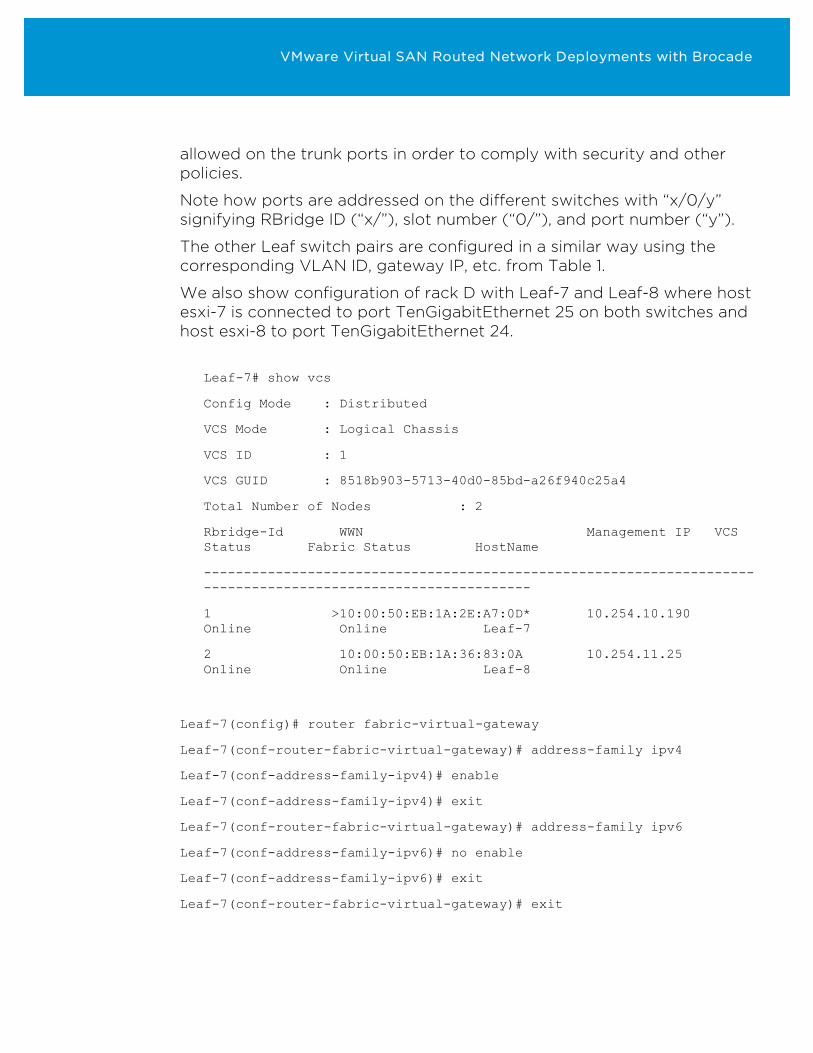
The other Leaf switch pairs are configured in a similar way using the corresponding VLAN ID, gateway IP, etc. from Table 1.
We also show configuration of rack D with Leaf-7 and Leaf-8 where host esxi-7 is connected to port TenGigabitEthernet 25 on both switches and host esxi-8 to port TenGigabitEthernet 24.
Leaf-7# show vcs
Config Mode : Distributed
VCS Mode : Logical Chassis
VCS ID : 1
VCS GUID : 8518b903-5713-40d0-85bd-a26f940c25a4
Total Number of Nodes : 2
Rbridge-Id WWN Management IP VCS Status Fabric Status HostName
--------------------------------------------------------------------------------------------------------------
1 >10:00:50:EB:1A:2E:A7:0D* 10.254.10.190 Online Online Leaf-7
2 10:00:50:EB:1A:36:83:0A 10.254.11.25 Online Online Leaf-8
Leaf-7(config)# router fabric-virtual-gateway
Leaf-7(conf-router-fabric-virtual-gateway)# address-family ipv4
Leaf-7(conf-address-family-ipv4)# enable
Leaf-7(conf-address-family-ipv4)# exit
Leaf-7(conf-router-fabric-virtual-gateway)# address-family ipv6
Leaf-7(conf-address-family-ipv6)# no enable
Leaf-7(conf-address-family-ipv6)# exit
Leaf-7(conf-router-fabric-virtual-gateway)# exit
VMware Virtual SAN Routed Network Deployments with Brocade
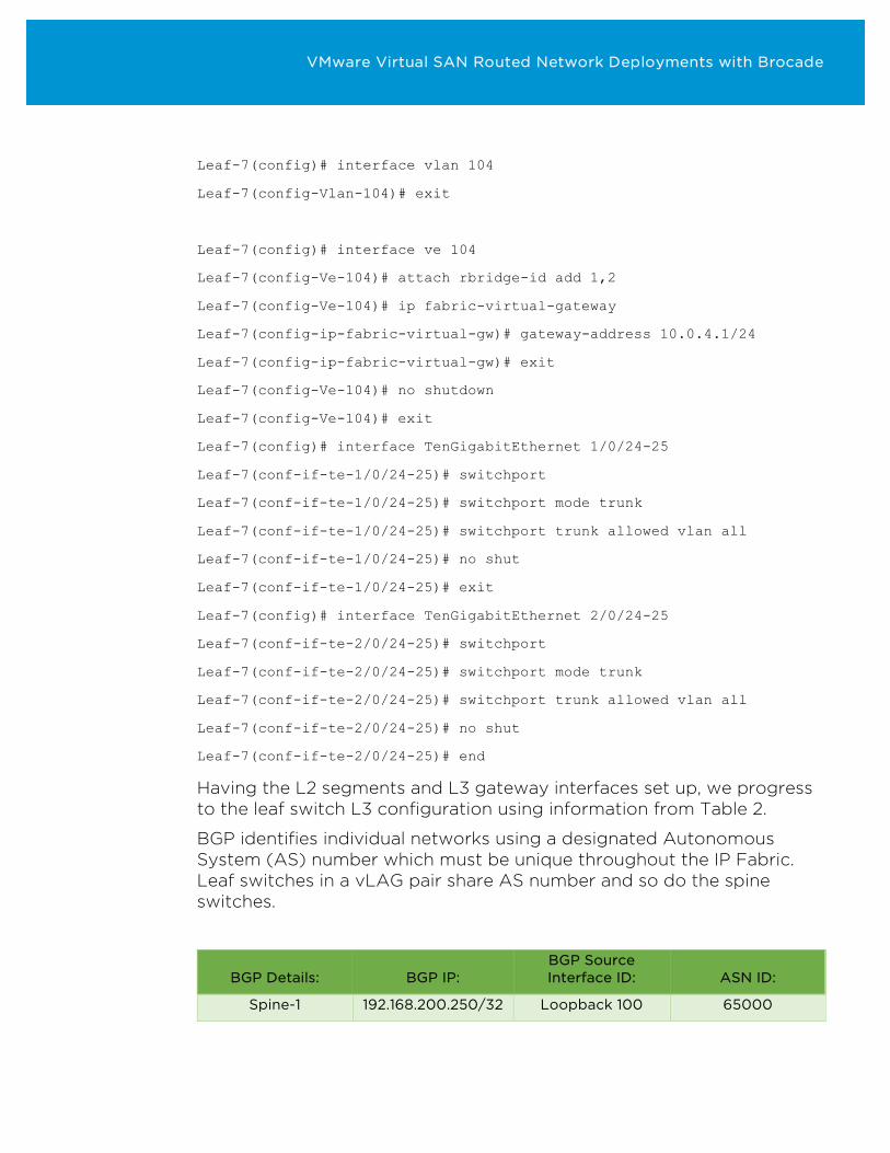
Leaf-7(config)# interface vlan 104
Leaf-7(config-Vlan-104)# exit
Leaf-7(config)# interface ve 104
Leaf-7(config-Ve-104)# attach rbridge-id add 1,2
Leaf-7(config-Ve-104)# ip fabric-virtual-gateway
Leaf-7(config-ip-fabric-virtual-gw)# gateway-address 10.0.4.1/24
Leaf-7(config-ip-fabric-virtual-gw)# exit
Leaf-7(config-Ve-104)# no shutdown
Leaf-7(config-Ve-104)# exit
Leaf-7(config)# interface TenGigabitEthernet 1/0/24-25
Leaf-7(conf-if-te-1/0/24-25)# switchport
Leaf-7(conf-if-te-1/0/24-25)# switchport mode trunk
Leaf-7(conf-if-te-1/0/24-25)# switchport trunk allowed vlan all
Leaf-7(conf-if-te-1/0/24-25)# no shut
Leaf-7(conf-if-te-1/0/24-25)# exit
Leaf-7(config)# interface TenGigabitEthernet 2/0/24-25
Leaf-7(conf-if-te-2/0/24-25)# switchport
Leaf-7(conf-if-te-2/0/24-25)# switchport mode trunk
Leaf-7(conf-if-te-2/0/24-25)# switchport trunk allowed vlan all
Leaf-7(conf-if-te-2/0/24-25)# no shut
Leaf-7(conf-if-te-2/0/24-25)# end
Having the L2 segments and L3 gateway interfaces set up, we progress to the leaf switch L3 configuration using information from Table 2.
BGP identifies individual networks using a designated Autonomous System (AS) number which must be unique throughout the IP Fabric. Leaf switches in a vLAG pair share AS number and so do the spine switches.
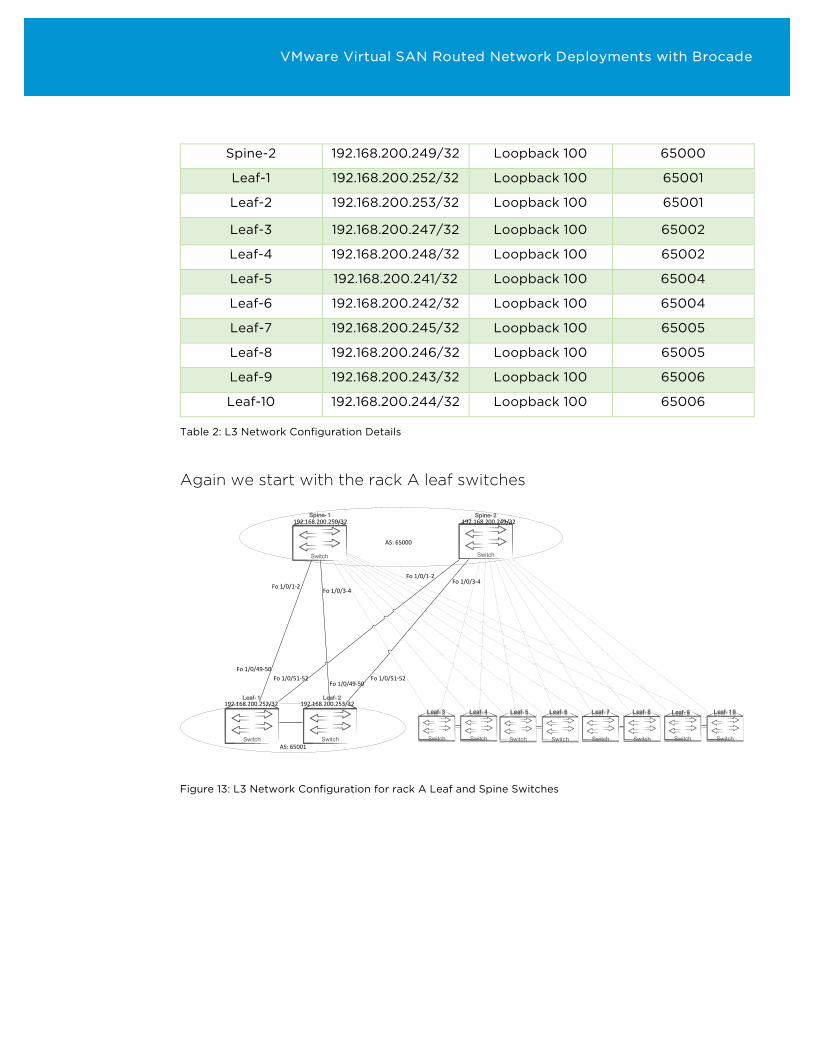
BGP Details: BGP IP: BGP Source Interface ID: ASN ID:
Spine-1 192.168.200.250/32 Loopback 100 65000
VMware Virtual SAN Routed Network Deployments with Brocade
Spine-2 192.168.200.249/32 Loopback 100 65000
Leaf-1 192.168.200.252/32 Loopback 100 65001
Leaf-2 192.168.200.253/32 Loopback 100 65001
Leaf-3 192.168.200.247/32 Loopback 100 65002
Leaf-4 192.168.200.248/32 Loopback 100 65002
Leaf-5 192.168.200.241/32 Loopback 100 65004
Leaf-6 192.168.200.242/32 Loopback 100 65004
Leaf-7 192.168.200.245/32 Loopback 100 65005
Leaf-8 192.168.200.246/32 Loopback 100 65005
Leaf-9 192.168.200.243/32 Loopback 100 65006
Leaf-10 192.168.200.244/32 Loopback 100 65006
Table 2: L3 Network Configuration Details
Again we start with the rack A leaf switches
Switch Switch
Switch Switch
Spine-1 Spine-2
Leaf-1 Leaf-2
Fo1/0/1-2Fo1/0/1-2
Fo1/0/49-50Fo1/0/51-52
Fo1/0/49-50Fo1/0/51-52
Fo1/0/3-4Fo1/0/3-4
AS:65001
AS:65000
192.168.200.250/32 192.168.200.249/32
192.168.200.252/32 192.168.200.253/32
Switch Switch Switch Switch Switch Switch Switch Switch
Leaf-3Leaf-3 Leaf-4Leaf-4 Leaf-5Leaf-5 Leaf-6Leaf-6 Leaf-7Leaf-7 Leaf-8Leaf-8 Leaf-9Leaf-9 Leaf-10Leaf-10
Figure 13: L3 Network Configuration for rack A Leaf and Spine Switches
VMware Virtual SAN Routed Network Deployments with Brocade
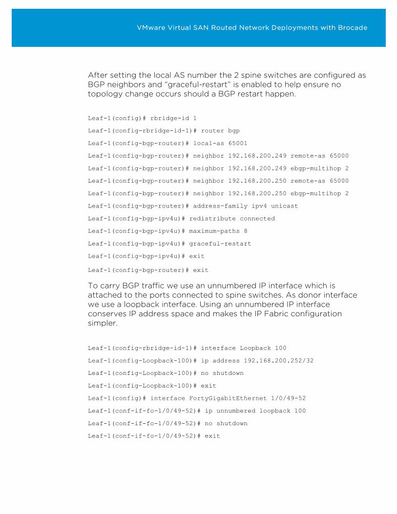
After setting the local AS number the 2 spine switches are configured as BGP neighbors and “graceful-restart” is enabled to help ensure no topology change occurs should a BGP restart happen.
Leaf-1(config)# rbridge-id 1
Leaf-1(config-rbridge-id-1)# router bgp
Leaf-1(config-bgp-router)# local-as 65001
Leaf-1(config-bgp-router)# neighbor 192.168.200.249 remote-as 65000
Leaf-1(config-bgp-router)# neighbor 192.168.200.249 ebgp-multihop 2
Leaf-1(config-bgp-router)# neighbor 192.168.200.250 remote-as 65000
Leaf-1(config-bgp-router)# neighbor 192.168.200.250 ebgp-multihop 2
Leaf-1(config-bgp-router)# address-family ipv4 unicast
Leaf-1(config-bgp-ipv4u)# redistribute connected
Leaf-1(config-bgp-ipv4u)# maximum-paths 8
Leaf-1(config-bgp-ipv4u)# graceful-restart
Leaf-1(config-bgp-ipv4u)# exit
Leaf-1(config-bgp-router)# exit
To carry BGP traffic we use an unnumbered IP interface which is attached to the ports connected to spine switches. As donor interface we use a loopback interface. Using an unnumbered IP interface conserves IP address space and makes the IP Fabric configuration simpler.
Leaf-1(config-rbridge-id-1)# interface Loopback 100
Leaf-1(config-Loopback-100)# ip address 192.168.200.252/32
Leaf-1(config-Loopback-100)# no shutdown
Leaf-1(config-Loopback-100)# exit
Leaf-1(config)# interface FortyGigabitEthernet 1/0/49-52
Leaf-1(conf-if-fo-1/0/49-52)# ip unnumbered loopback 100
Leaf-1(conf-if-fo-1/0/49-52)# no shutdown
Leaf-1(conf-if-fo-1/0/49-52)# exit
VMware Virtual SAN Routed Network Deployments with Brocade
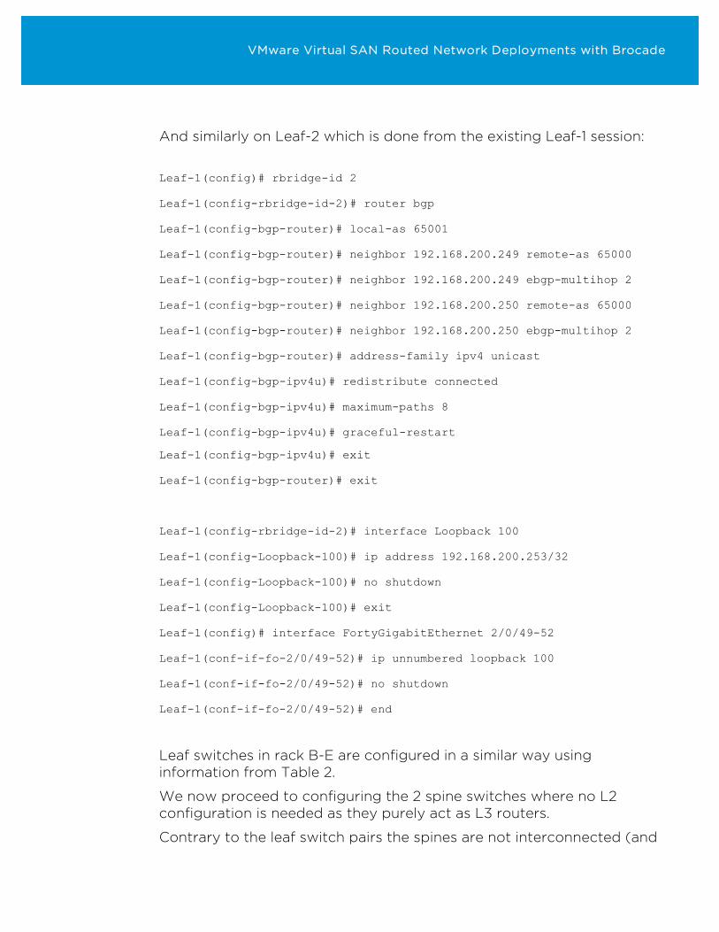
And similarly on Leaf-2 which is done from the existing Leaf-1 session:
Leaf-1(config)# rbridge-id 2
Leaf-1(config-rbridge-id-2)# router bgp
Leaf-1(config-bgp-router)# local-as 65001
Leaf-1(config-bgp-router)# neighbor 192.168.200.249 remote-as 65000
Leaf-1(config-bgp-router)# neighbor 192.168.200.249 ebgp-multihop 2
Leaf-1(config-bgp-router)# neighbor 192.168.200.250 remote-as 65000
Leaf-1(config-bgp-router)# neighbor 192.168.200.250 ebgp-multihop 2
Leaf-1(config-bgp-router)# address-family ipv4 unicast
Leaf-1(config-bgp-ipv4u)# redistribute connected
Leaf-1(config-bgp-ipv4u)# maximum-paths 8
Leaf-1(config-bgp-ipv4u)# graceful-restart
Leaf-1(config-bgp-ipv4u)# exit
Leaf-1(config-bgp-router)# exit
Leaf-1(config-rbridge-id-2)# interface Loopback 100
Leaf-1(config-Loopback-100)# ip address 192.168.200.253/32
Leaf-1(config-Loopback-100)# no shutdown
Leaf-1(config-Loopback-100)# exit
Leaf-1(config)# interface FortyGigabitEthernet 2/0/49-52
Leaf-1(conf-if-fo-2/0/49-52)# ip unnumbered loopback 100
Leaf-1(conf-if-fo-2/0/49-52)# no shutdown
Leaf-1(conf-if-fo-2/0/49-52)# end
Leaf switches in rack B-E are configured in a similar way using information from Table 2.
We now proceed to configuring the 2 spine switches where no L2 configuration is needed as they purely act as L3 routers.
Contrary to the leaf switch pairs the spines are not interconnected (and
VMware Virtual SAN Routed Network Deployments with Brocade
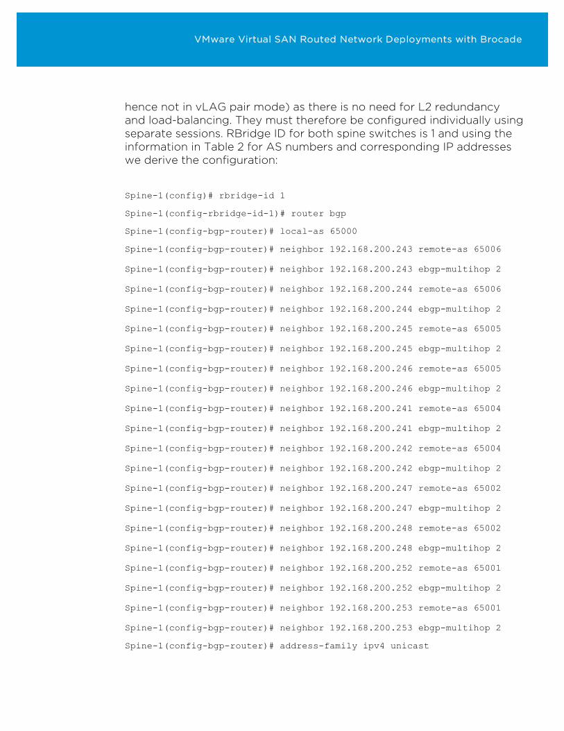
hence not in vLAG pair mode) as there is no need for L2 redundancy and load-balancing. They must therefore be configured individually using separate sessions. RBridge ID for both spine switches is 1 and using the information in Table 2 for AS numbers and corresponding IP addresses we derive the configuration:
Spine-1(config)# rbridge-id 1
Spine-1(config-rbridge-id-1)# router bgp
Spine-1(config-bgp-router)# local-as 65000
Spine-1(config-bgp-router)# neighbor 192.168.200.243 remote-as 65006
Spine-1(config-bgp-router)# neighbor 192.168.200.243 ebgp-multihop 2
Spine-1(config-bgp-router)# neighbor 192.168.200.244 remote-as 65006
Spine-1(config-bgp-router)# neighbor 192.168.200.244 ebgp-multihop 2
Spine-1(config-bgp-router)# neighbor 192.168.200.245 remote-as 65005
Spine-1(config-bgp-router)# neighbor 192.168.200.245 ebgp-multihop 2
Spine-1(config-bgp-router)# neighbor 192.168.200.246 remote-as 65005
Spine-1(config-bgp-router)# neighbor 192.168.200.246 ebgp-multihop 2
Spine-1(config-bgp-router)# neighbor 192.168.200.241 remote-as 65004
Spine-1(config-bgp-router)# neighbor 192.168.200.241 ebgp-multihop 2
Spine-1(config-bgp-router)# neighbor 192.168.200.242 remote-as 65004
Spine-1(config-bgp-router)# neighbor 192.168.200.242 ebgp-multihop 2
Spine-1(config-bgp-router)# neighbor 192.168.200.247 remote-as 65002
Spine-1(config-bgp-router)# neighbor 192.168.200.247 ebgp-multihop 2
Spine-1(config-bgp-router)# neighbor 192.168.200.248 remote-as 65002
Spine-1(config-bgp-router)# neighbor 192.168.200.248 ebgp-multihop 2
Spine-1(config-bgp-router)# neighbor 192.168.200.252 remote-as 65001
Spine-1(config-bgp-router)# neighbor 192.168.200.252 ebgp-multihop 2
Spine-1(config-bgp-router)# neighbor 192.168.200.253 remote-as 65001
Spine-1(config-bgp-router)# neighbor 192.168.200.253 ebgp-multihop 2
Spine-1(config-bgp-router)# address-family ipv4 unicast
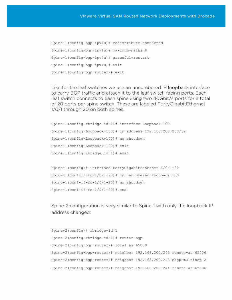
VMware Virtual SAN Routed Network Deployments with Brocade
Spine-1(config-bgp-ipv4u)# redistribute connected
Spine-1(config-bgp-ipv4u)# maximum-paths 8
Spine-1(config-bgp-ipv4u)# graceful-restart
Spine-1(config-bgp-ipv4u)# exit
Spine-1(config-bgp-router)# exit
Like for the leaf switches we use an unnumbered IP loopback interface to carry BGP traffic and attach it to the leaf switch facing ports. Each leaf switch connects to each spine using two 40Gbit/s ports for a total of 20 ports per spine switch. These are labeled FortyGigabitEthernet 1/0/1 through 20 on both spines.
Spine-1(config-rbridge-id-1)# interface Loopback 100
Spine-1(config-Loopback-100)# ip address 192.168.200.250/32
Spine-1(config-Loopback-100)# no shutdown
Spine-1(config-Loopback-100)# exit
Spine-1(config-rbridge-id-1)# exit
Spine-1(config)# interface FortyGigabitEthernet 1/0/1-20
Spine-1(conf-if-fo-1/0/1-20)# ip unnumbered loopback 100
Spine-1(conf-if-fo-1/0/1-20)# no shutdown
Spine-1(conf-if-fo-1/0/1-20)# end
Spine-2 configuration is very similar to Spine-1 with only the loopback IP address changed:
Spine-2(config)# rbridge-id 1
Spine-2(config-rbridge-id-1)# router bgp
Spine-2(config-bgp-router)# local-as 65000
Spine-2(config-bgp-router)# neighbor 192.168.200.243 remote-as 65006
Spine-2(config-bgp-router)# neighbor 192.168.200.243 ebgp-multihop 2
Spine-2(config-bgp-router)# neighbor 192.168.200.244 remote-as 65006
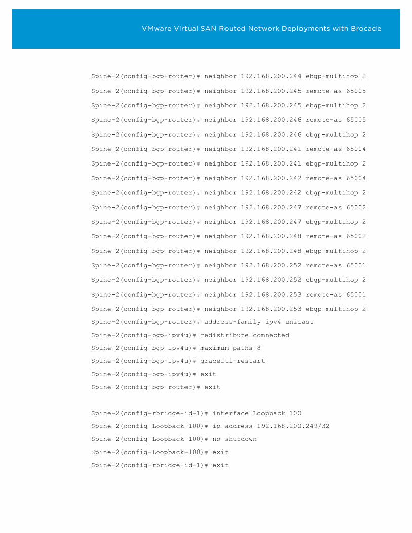
VMware Virtual SAN Routed Network Deployments with Brocade
Spine-2(config-bgp-router)# neighbor 192.168.200.244 ebgp-multihop 2
Spine-2(config-bgp-router)# neighbor 192.168.200.245 remote-as 65005
Spine-2(config-bgp-router)# neighbor 192.168.200.245 ebgp-multihop 2
Spine-2(config-bgp-router)# neighbor 192.168.200.246 remote-as 65005
Spine-2(config-bgp-router)# neighbor 192.168.200.246 ebgp-multihop 2
Spine-2(config-bgp-router)# neighbor 192.168.200.241 remote-as 65004
Spine-2(config-bgp-router)# neighbor 192.168.200.241 ebgp-multihop 2
Spine-2(config-bgp-router)# neighbor 192.168.200.242 remote-as 65004
Spine-2(config-bgp-router)# neighbor 192.168.200.242 ebgp-multihop 2
Spine-2(config-bgp-router)# neighbor 192.168.200.247 remote-as 65002
Spine-2(config-bgp-router)# neighbor 192.168.200.247 ebgp-multihop 2
Spine-2(config-bgp-router)# neighbor 192.168.200.248 remote-as 65002
Spine-2(config-bgp-router)# neighbor 192.168.200.248 ebgp-multihop 2
Spine-2(config-bgp-router)# neighbor 192.168.200.252 remote-as 65001
Spine-2(config-bgp-router)# neighbor 192.168.200.252 ebgp-multihop 2
Spine-2(config-bgp-router)# neighbor 192.168.200.253 remote-as 65001
Spine-2(config-bgp-router)# neighbor 192.168.200.253 ebgp-multihop 2
Spine-2(config-bgp-router)# address-family ipv4 unicast
Spine-2(config-bgp-ipv4u)# redistribute connected
Spine-2(config-bgp-ipv4u)# maximum-paths 8
Spine-2(config-bgp-ipv4u)# graceful-restart
Spine-2(config-bgp-ipv4u)# exit
Spine-2(config-bgp-router)# exit
Spine-2(config-rbridge-id-1)# interface Loopback 100
Spine-2(config-Loopback-100)# ip address 192.168.200.249/32
Spine-2(config-Loopback-100)# no shutdown
Spine-2(config-Loopback-100)# exit
Spine-2(config-rbridge-id-1)# exit
VMware Virtual SAN Routed Network Deployments with Brocade
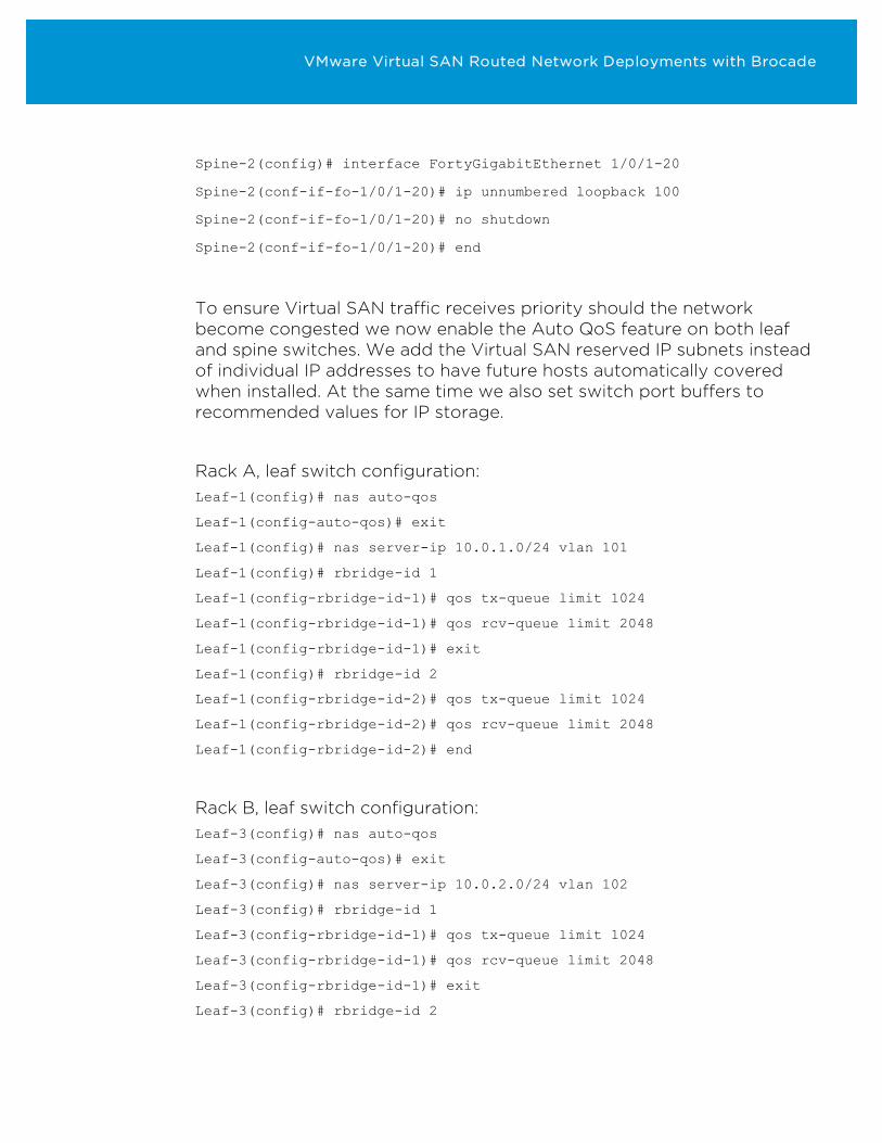
Spine-2(config)# interface FortyGigabitEthernet 1/0/1-20
Spine-2(conf-if-fo-1/0/1-20)# ip unnumbered loopback 100
Spine-2(conf-if-fo-1/0/1-20)# no shutdown
Spine-2(conf-if-fo-1/0/1-20)# end
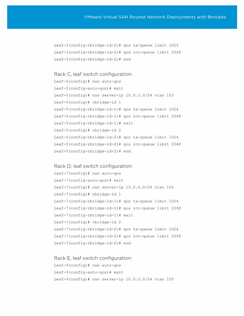
To ensure Virtual SAN traffic receives priority should the network become congested we now enable the Auto QoS feature on both leaf and spine switches. We add the Virtual SAN reserved IP subnets instead of individual IP addresses to have future hosts automatically covered when installed. At the same time we also set switch port buffers to recommended values for IP storage.
Rack A, leaf switch configuration: Leaf-1(config)# nas auto-qos
Leaf-1(config-auto-qos)# exit
Leaf-1(config)# nas server-ip 10.0.1.0/24 vlan 101
Leaf-1(config)# rbridge-id 1
Leaf-1(config-rbridge-id-1)# qos tx-queue limit 1024
Leaf-1(config-rbridge-id-1)# qos rcv-queue limit 2048
Leaf-1(config-rbridge-id-1)# exit
Leaf-1(config)# rbridge-id 2
Leaf-1(config-rbridge-id-2)# qos tx-queue limit 1024
Leaf-1(config-rbridge-id-2)# qos rcv-queue limit 2048
Leaf-1(config-rbridge-id-2)# end
Rack B, leaf switch configuration: Leaf-3(config)# nas auto-qos
Leaf-3(config-auto-qos)# exit
Leaf-3(config)# nas server-ip 10.0.2.0/24 vlan 102
Leaf-3(config)# rbridge-id 1
Leaf-3(config-rbridge-id-1)# qos tx-queue limit 1024
Leaf-3(config-rbridge-id-1)# qos rcv-queue limit 2048
Leaf-3(config-rbridge-id-1)# exit
Leaf-3(config)# rbridge-id 2
VMware Virtual SAN Routed Network Deployments with Brocade
Leaf-3(config-rbridge-id-2)# qos tx-queue limit 1024
Leaf-3(config-rbridge-id-2)# qos rcv-queue limit 2048
Leaf-3(config-rbridge-id-2)# end
Rack C, leaf switch configuration: Leaf-5(config)# nas auto-qos
Leaf-5(config-auto-qos)# exit
Leaf-5(config)# nas server-ip 10.0.3.0/24 vlan 103
Leaf-5(config)# rbridge-id 1
Leaf-5(config-rbridge-id-1)# qos tx-queue limit 1024
Leaf-5(config-rbridge-id-1)# qos rcv-queue limit 2048
Leaf-5(config-rbridge-id-1)# exit
Leaf-5(config)# rbridge-id 2
Leaf-5(config-rbridge-id-2)# qos tx-queue limit 1024
Leaf-5(config-rbridge-id-2)# qos rcv-queue limit 2048
Leaf-5(config-rbridge-id-2)# end
Rack D, leaf switch configuration: Leaf-7(config)# nas auto-qos
Leaf-7(config-auto-qos)# exit
Leaf-7(config)# nas server-ip 10.0.4.0/24 vlan 104
Leaf-7(config)# rbridge-id 1
Leaf-7(config-rbridge-id-1)# qos tx-queue limit 1024
Leaf-7(config-rbridge-id-1)# qos rcv-queue limit 2048
Leaf-7(config-rbridge-id-1)# exit
Leaf-7(config)# rbridge-id 2
Leaf-7(config-rbridge-id-2)# qos tx-queue limit 1024
Leaf-7(config-rbridge-id-2)# qos rcv-queue limit 2048
Leaf-7(config-rbridge-id-2)# end
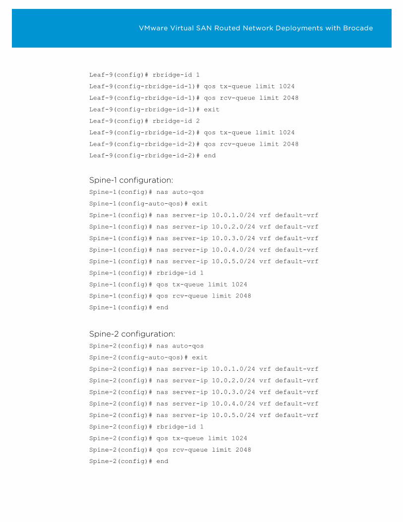
Rack E, leaf switch configuration: Leaf-9(config)# nas auto-qos
Leaf-9(config-auto-qos)# exit
Leaf-9(config)# nas server-ip 10.0.5.0/24 vlan 105
VMware Virtual SAN Routed Network Deployments with Brocade
Leaf-9(config)# rbridge-id 1
Leaf-9(config-rbridge-id-1)# qos tx-queue limit 1024
Leaf-9(config-rbridge-id-1)# qos rcv-queue limit 2048
Leaf-9(config-rbridge-id-1)# exit
Leaf-9(config)# rbridge-id 2
Leaf-9(config-rbridge-id-2)# qos tx-queue limit 1024
Leaf-9(config-rbridge-id-2)# qos rcv-queue limit 2048
Leaf-9(config-rbridge-id-2)# end
Spine-1 configuration: Spine-1(config)# nas auto-qos
Spine-1(config-auto-qos)# exit
Spine-1(config)# nas server-ip 10.0.1.0/24 vrf default-vrf
Spine-1(config)# nas server-ip 10.0.2.0/24 vrf default-vrf
Spine-1(config)# nas server-ip 10.0.3.0/24 vrf default-vrf
Spine-1(config)# nas server-ip 10.0.4.0/24 vrf default-vrf
Spine-1(config)# nas server-ip 10.0.5.0/24 vrf default-vrf
Spine-1(config)# rbridge-id 1
Spine-1(config)# qos tx-queue limit 1024
Spine-1(config)# qos rcv-queue limit 2048
Spine-1(config)# end
Spine-2 configuration: Spine-2(config)# nas auto-qos
Spine-2(config-auto-qos)# exit
Spine-2(config)# nas server-ip 10.0.1.0/24 vrf default-vrf
Spine-2(config)# nas server-ip 10.0.2.0/24 vrf default-vrf
Spine-2(config)# nas server-ip 10.0.3.0/24 vrf default-vrf
Spine-2(config)# nas server-ip 10.0.4.0/24 vrf default-vrf
Spine-2(config)# nas server-ip 10.0.5.0/24 vrf default-vrf
Spine-2(config)# rbridge-id 1
Spine-2(config)# qos tx-queue limit 1024
Spine-2(config)# qos rcv-queue limit 2048
Spine-2(config)# end
VMware Virtual SAN Routed Network Deployments with Brocade
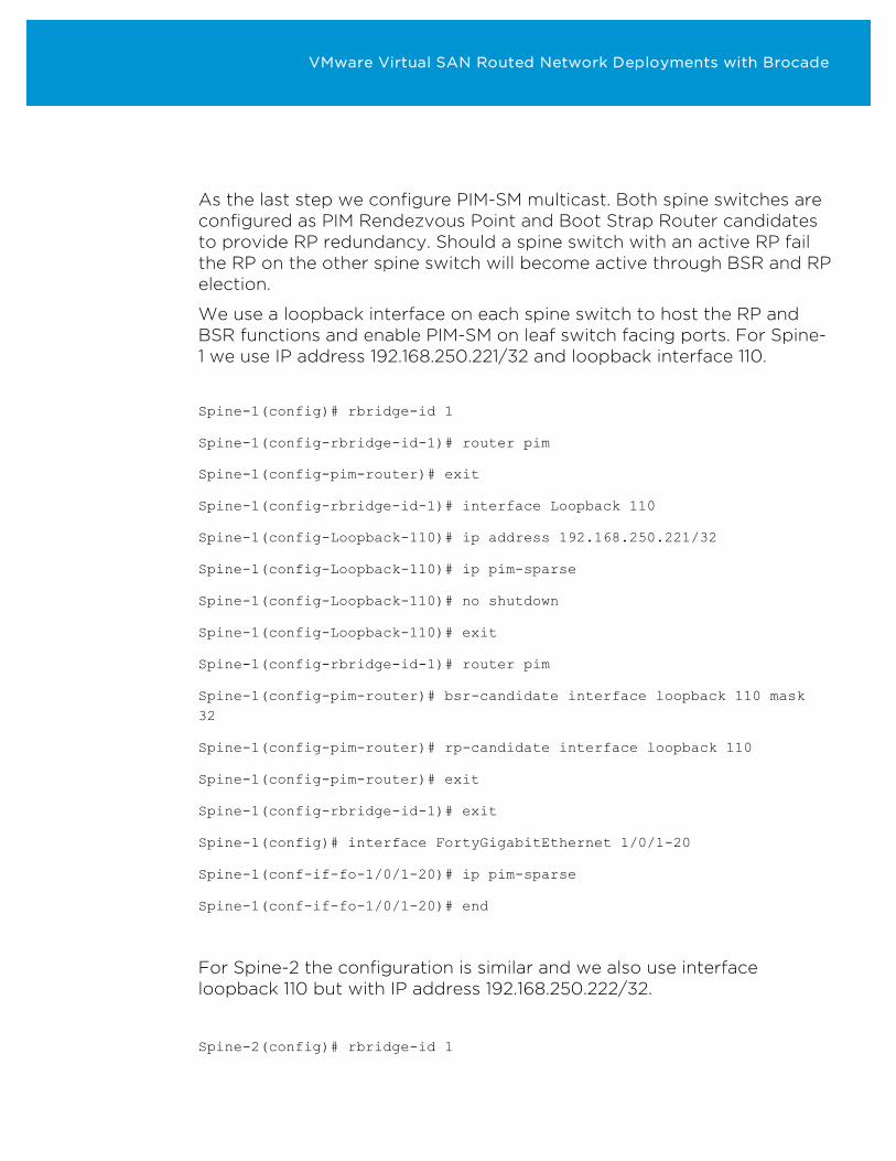
As the last step we configure PIM-SM multicast. Both spine switches are configured as PIM Rendezvous Point and Boot Strap Router candidates to provide RP redundancy. Should a spine switch with an active RP fail the RP on the other spine switch will become active through BSR and RP election.
We use a loopback interface on each spine switch to host the RP and BSR functions and enable PIM-SM on leaf switch facing ports. For Spine-1 we use IP address 192.168.250.221/32 and loopback interface 110.
Spine-1(config)# rbridge-id 1
Spine-1(config-rbridge-id-1)# router pim
Spine-1(config-pim-router)# exit
Spine-1(config-rbridge-id-1)# interface Loopback 110
Spine-1(config-Loopback-110)# ip address 192.168.250.221/32
Spine-1(config-Loopback-110)# ip pim-sparse
Spine-1(config-Loopback-110)# no shutdown
Spine-1(config-Loopback-110)# exit
Spine-1(config-rbridge-id-1)# router pim
Spine-1(config-pim-router)# bsr-candidate interface loopback 110 mask 32
Spine-1(config-pim-router)# rp-candidate interface loopback 110
Spine-1(config-pim-router)# exit
Spine-1(config-rbridge-id-1)# exit
Spine-1(config)# interface FortyGigabitEthernet 1/0/1-20
Spine-1(conf-if-fo-1/0/1-20)# ip pim-sparse
Spine-1(conf-if-fo-1/0/1-20)# end
For Spine-2 the configuration is similar and we also use interface loopback 110 but with IP address 192.168.250.222/32.
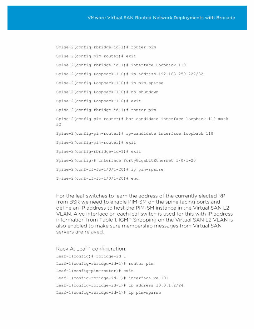
Spine-2(config)# rbridge-id 1
VMware Virtual SAN Routed Network Deployments with Brocade
Spine-2(config-rbridge-id-1)# router pim
Spine-2(config-pim-router)# exit
Spine-2(config-rbridge-id-1)# interface Loopback 110
Spine-2(config-Loopback-110)# ip address 192.168.250.222/32
Spine-2(config-Loopback-110)# ip pim-sparse
Spine-2(config-Loopback-110)# no shutdown
Spine-2(config-Loopback-110)# exit
Spine-2(config-rbridge-id-1)# router pim
Spine-2(config-pim-router)# bsr-candidate interface loopback 110 mask 32
Spine-2(config-pim-router)# rp-candidate interface loopback 110
Spine-2(config-pim-router)# exit
Spine-2(config-rbridge-id-1)# exit
Spine-2(config)# interface FortyGigabitEthernet 1/0/1-20
Spine-2(conf-if-fo-1/0/1-20)# ip pim-sparse
Spine-2(conf-if-fo-1/0/1-20)# end
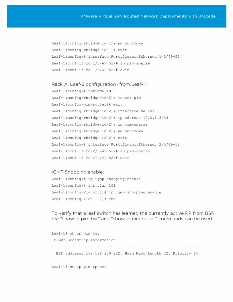
For the leaf switches to learn the address of the currently elected RP from BSR we need to enable PIM-SM on the spine facing ports and define an IP address to host the PIM-SM instance in the Virtual SAN L2 VLAN. A ve interface on each leaf switch is used for this with IP address information from Table 1. IGMP Snooping on the Virtual SAN L2 VLAN is also enabled to make sure membership messages from Virtual SAN servers are relayed.
Rack A, Leaf-1 configuration: Leaf-1(config)# rbridge-id 1
Leaf-1(config-rbridge-id-1)# router pim
Leaf-1(config-pim-router)# exit
Leaf-1(config-rbridge-id-1)# interface ve 101
Leaf-1(config-rbridge-id-1)# ip address 10.0.1.2/24
Leaf-1(config-rbridge-id-1)# ip pim-sparse
VMware Virtual SAN Routed Network Deployments with Brocade
Leaf-1(config-rbridge-id-1)# no shutdown
Leaf-1(config-rbridge-id-1)# exit
Leaf-1(config)# interface FortyGigabitEthernet 1/0/49-52
Leaf-1(conf-if-fo-1/0/49-52)# ip pim-sparse
Leaf-1(conf-if-fo-1/0/49-52)# exit
Rack A, Leaf-2 configuration (from Leaf-1): Leaf-1(config)# rbridge-id 2
Leaf-1(config-rbridge-id-2)# router pim
Leaf-1(config-pim-router)# exit
Leaf-1(config-rbridge-id-2)# interface ve 101
Leaf-1(config-rbridge-id-2)# ip address 10.0.1.3/24
Leaf-1(config-rbridge-id-2)# ip pim-sparse
Leaf-1(config-rbridge-id-2)# no shutdown
Leaf-1(config-rbridge-id-2)# exit
Leaf-1(config)# interface FortyGigabitEthernet 2/0/49-52
Leaf-1(conf-if-fo-2/0/49-52)# ip pim-sparse
Leaf-1(conf-if-fo-2/0/49-52)# exit
IGMP Snooping enable: Leaf-1(config)# ip igmp snooping enable
Leaf-1(config)# int vlan 101
Leaf-1(config-Vlan-101)# ip igmp snooping enable
Leaf-1(config-Vlan-101)# end
To verify that a leaf switch has learned the currently active RP from BSR the “show ip pim bsr” and “show ip pim rp-set” commands can be used.
Leaf-1# sh ip pim bsr
PIMv2 Bootstrap information :
------------------------------------------------------------------
BSR address: 192.168.250.222. Hash Mask Length 32. Priority 64.
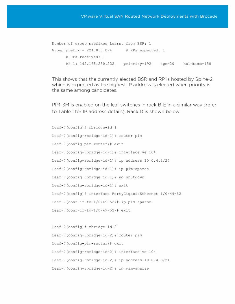
Leaf-1# sh ip pim rp-set
VMware Virtual SAN Routed Network Deployments with Brocade
Number of group prefixes Learnt from BSR: 1
Group prefix = 224.0.0.0/4 # RPs expected: 1
# RPs received: 1
RP 1: 192.168.250.222 priority=192 age=20 holdtime=150
This shows that the currently elected BSR and RP is hosted by Spine-2, which is expected as the highest IP address is elected when priority is the same among candidates.
PIM-SM is enabled on the leaf switches in rack B-E in a similar way (refer to Table 1 for IP address details). Rack D is shown below:
Leaf-7(config)# rbridge-id 1
Leaf-7(config-rbridge-id-1)# router pim
Leaf-7(config-pim-router)# exit
Leaf-7(config-rbridge-id-1)# interface ve 104
Leaf-7(config-rbridge-id-1)# ip address 10.0.4.2/24
Leaf-7(config-rbridge-id-1)# ip pim-sparse
Leaf-7(config-rbridge-id-1)# no shutdown
Leaf-7(config-rbridge-id-1)# exit
Leaf-7(config)# interface FortyGigabitEthernet 1/0/49-52
Leaf-7(conf-if-fo-1/0/49-52)# ip pim-sparse
Leaf-7(conf-if-fo-1/0/49-52)# exit
Leaf-7(config)# rbridge-id 2
Leaf-7(config-rbridge-id-2)# router pim
Leaf-7(config-pim-router)# exit
Leaf-7(config-rbridge-id-2)# interface ve 104
Leaf-7(config-rbridge-id-2)# ip address 10.0.4.3/24
Leaf-7(config-rbridge-id-2)# ip pim-sparse
VMware Virtual SAN Routed Network Deployments with Brocade
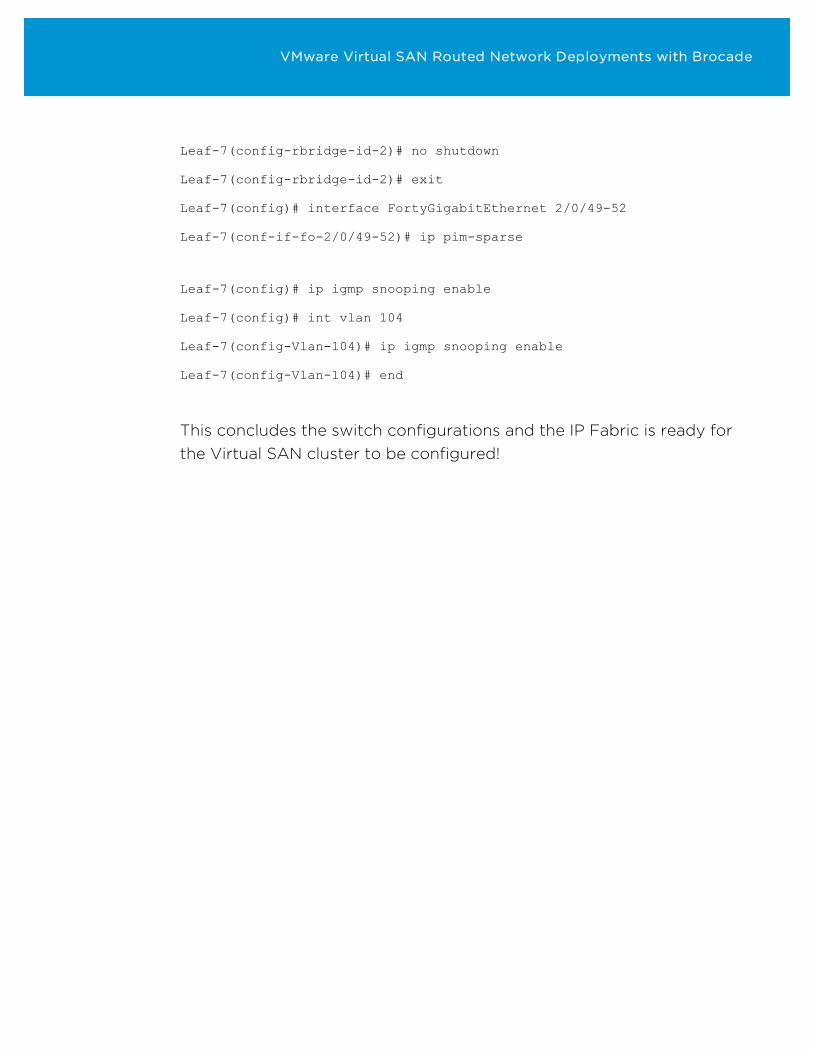
Leaf-7(config-rbridge-id-2)# no shutdown
Leaf-7(config-rbridge-id-2)# exit
Leaf-7(config)# interface FortyGigabitEthernet 2/0/49-52
Leaf-7(conf-if-fo-2/0/49-52)# ip pim-sparse
Leaf-7(config)# ip igmp snooping enable
Leaf-7(config)# int vlan 104
Leaf-7(config-Vlan-104)# ip igmp snooping enable
Leaf-7(config-Vlan-104)# end
This concludes the switch configurations and the IP Fabric is ready for the Virtual SAN cluster to be configured!
VMware Virtual SAN Routed Network Deployments with Brocade
Network Automation & Orchestration To ensure configuration consistency, design adherence, and to ease manual management tasks, the process of configuring the Brocade IP Fabric for VMware Virtual SAN can be automated using the Brocade Workflow Composer (BWC).
Based on workflows grouping the sequence of tasks through which a configuration change is implemented, Brocade Workflow Composer provides a software-driven network automation platform integrating cross-domain everyday tasks.
Based on a micro-services architecture and Powered by StackStorm, an innovator in event-driven, DevOps-style, cross-domain automation, Brocade Workflow Composer provides nearly 2000 points of integration with popular platforms and technologies.
Workflows are composed using 3 key technologies working hand-in-hand.
- Sensors: Listens for specific events through integrating with infrastructure and applications using APIs
- Actions: Executes commands through integrating with infrastructure and applications using APIs
- Rules: Uses IFTTT (if-then-this-that) logic to determine what actions to perform based on input from Sensors
VMware Virtual SAN Routed Network Deployments with Brocade
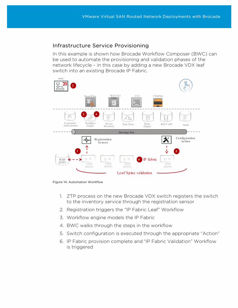
Infrastructure Service Provisioning In this example is shown how Brocade Workflow Composer (BWC) can be used to automate the provisioning and validation phases of the network lifecycle – in this case by adding a new Brocade VDX leaf switch into an existing Brocade IP Fabric.
Rules Engine
Credential / Authorization
Device Inventory
Workflow Engine Data Store REST AP I
Web GUI CLIVisual Flow
//
ChatOps
Message Bus
Audit
VDX (NOS)
VDX (NOS)
VDX (NOS)
VDX (NOS)
DAD(ZTP)
1
Registration Sensor
Configuration Action
5
2
3 4
6 IP fabric
Leaf/ Spine validation
BWC
Figure 14: Automation Workflow
1. ZTP process on the new Brocade VDX switch registers the switch
to the inventory service through the registration sensor
2. Registration triggers the “IP Fabric Leaf” Workflow
3. Workflow engine models the IP Fabric
4. BWC walks through the steps in the workflow
5. Switch configuration is executed through the appropriate “Action”
6. IP Fabric provision complete and “IP Fabric Validation” Workflow is triggered
VMware Virtual SAN Routed Network Deployments with Brocade
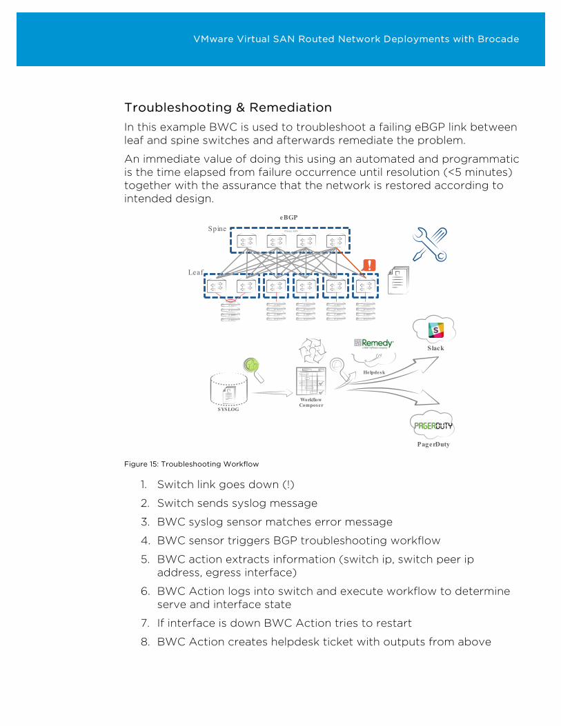
Troubleshooting & Remediation In this example BWC is used to troubleshoot a failing eBGP link between leaf and spine switches and afterwards remediate the problem.
An immediate value of doing this using an automated and programmatic is the time elapsed from failure occurrence until resolution (<5 minutes) together with the assurance that the network is restored according to intended design.
Spine
Leaf
eBGP
Private ASN
SYSLOG
Workflow Composer
Slack
PagerDuty
Helpdesk
Figure 15: Troubleshooting Workflow
1. Switch link goes down (!)
2. Switch sends syslog message
3. BWC syslog sensor matches error message
4. BWC sensor triggers BGP troubleshooting workflow
5. BWC action extracts information (switch ip, switch peer ip address, egress interface)
6. BWC Action logs into switch and execute workflow to determine serve and interface state
7. If interface is down BWC Action tries to restart
8. BWC Action creates helpdesk ticket with outputs from above
VMware Virtual SAN Routed Network Deployments with Brocade
9. BWC initiates an Alert workflow if interface could not be restarted
o Include Helpdesk ID and URL
o Post message to eg. Slack for Network Ops team visibility
o Launch incident to PagerDuty to notify Operator on duty
VMware Virtual SAN Routed Network Deployments with Brocade
Summary VMware Virtual SAN is the next evolution in Storage Virtualization. Virtual SAN implementations utilize the already existing IP Network infrastructure to maximize return on investment while reducing OPEX.
From a deployment perspective, the Virtual SAN network stack is flexible and supported over Layer 2 and Layer 3 network topologies.
While Virtual SAN implementations over Layer 2 network topologies present the least amount of network complexity to implement and simplest option to manage and maintain, the ability of Virtual SAN to natively function in a massively scalable L3 topology shows the flexibility and power of the solution.
Either way, VMware Virtual SAN deployments can be performed on Layer 2 as well as Layer 3 networking topologies right out-of-the box.
Acknowledgments We would like to thank Christos Karamanolis, Fellow and CTO of the Storage and Availability Business Unit at VMware, Ken Werneburg, Manager of the Storage and Availability Technical marketing team at VMware, Reshma Sudarshan, Sr. Manager Software Engineering at Brocade, Srikanth Mulakaluri, Sr. Staff Software Engineer at Brocade, Chirag Taunk, Software Engineer at Brocade, and Marcus Thordal, Director Technical Solutions at Brocade for reviewing this paper.
VMware Virtual SAN Routed Network Deployments with Brocade
Author Rawlinson Rivera is a Principal Architect in the Office of the CTO for the Storage and Availability Business Unit at VMware, Inc. He specializes in cloud enterprise architectures, and Hyper-Converged Infrastructures (HCI).
Primarily focused on Software-Defined Storage products and technologies such as Virtual SAN, vSphere Virtual Volumes, as well as storage related solutions for OpenStack and Cloud-Native Applications. He serves as a trusted adviser to VMware's customers primarily in the US.
Rawlinson is amongst the few VMware Certified Design Experts (VCDX#86) in the world, and is an author of multiple text books publications based on VMware and other technologies. He is the owner and main author of virtualization blog punchingclouds.com.
• Follow Rawlinson’s blogs:
http://blogs.vmware.com/vsphere/storage http://www.punchingclouds.com/
• Follow Rawlinson on Twitter:
@PunchingClouds
Nikolaj Kjeldsen is a Global Architect in the Technology Solutions group at Brocade Communications.
With a background in Storage, Converged Infrastructure, and Networking he architects solutions from a business and application perspective while ensuring the value of the network is fully unlocked.
Nikolaj is active in the enterprise IT architecture community and an author of several publications. He holds a MSc. Degree in Telecommunications engineering.
• Follow Nikolaj on Twitter
@nikolajbk

VMware Virtual SAN Routed Network Deployments with Brocade