Embed Size (px)
Citation preview
PowerBack PB5000
5KVA 220-230Vac 48Vdc INVERTER / CHARGER
USER MANUAL
t h e p o w e r t o p r o t e c t
2 S o l l a t e k P o w e r B a c k M a N U a l
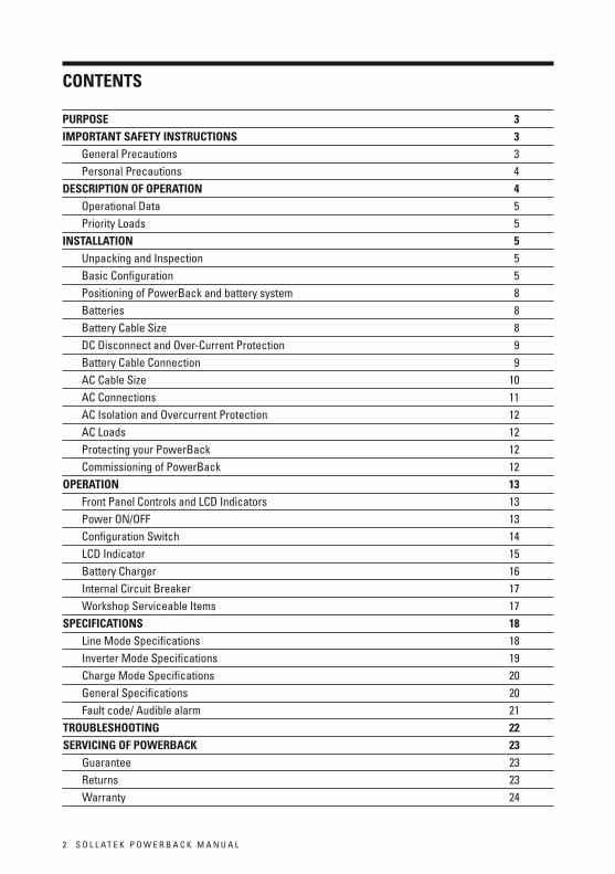
Contents
PURPose 3IMPoRtAntsAFetYInstRUCtIons 3 General Precautions 3 Personal Precautions 4 DesCRIPtIonoFoPeRAtIon 4 operational Data 5 Priority loads 5InstALLAtIon 5 Unpacking and Inspection 5 Basic configuration 5 Positioning of PowerBack and battery system 8 Batteries 8 Battery cable Size 8 Dc Disconnect and over-current Protection 9 Battery cable connection 9 ac cable Size 10 ac connections 11 ac Isolation and overcurrent Protection 12 ac loads 12 Protecting your PowerBack 12 commissioning of PowerBack 12oPeRAtIon 13 Front Panel controls and lcD Indicators 13 Power oN/oFF 13 configuration Switch 14 lcD Indicator 15 Battery charger 16 Internal circuit Breaker 17 workshop Serviceable Items 17sPeCIFICAtIons 18 line Mode Specifications 18 Inverter Mode Specifications 19 charge Mode Specifications 20 General Specifications 20 Fault code/ audible alarm 21 tRoUBLesHootInG 22seRVICInGoFPoWeRBACK 23 Guarantee 23 returns 23 warranty 24
S o l l a t e k P o w e r B a c k M a N U a l 3
PURPosethis manual explains procedures for the unit’s installation, operation and troubleshooting Please take time to understand the contents of this manual prior to installation and operation.
IMPoRtAntsAFetYInstRUCtIonswarNING: this chapter contains important safety and operating instructions. read and keep this User Guide for future reference. Display this notice at location of batteries.
GeneralPrecautions1. Before using the unit, read all instructions and cautionary markings on: the unit (2) the batteries (3) all appropriate sections of this manual.
2. CAUtIon -to reduce risk of injury, charge only deep-cycle lead acid type rechargeable batteries. other types of batteries may burst, causing personal injury and damage.
3. Do not expose the unit to rain, snow or liquids of any type. the unit is designed for indoor use only. Protect the unit from splashing if used in vehicle applications.
4. Do not disassemble the unit. take it to a qualified Sollatek service center when service or repair is required. Incorrect re-assembly may result in a risk of electric shock or fire.
5. to reduce risk of electric shock, disconnect all wiring before attempting any maintenance or cleaning. turning off the unit will not reduce this risk.
WARnInG:WoRKInGInVICInItYoFALeADACIDBAtteRYIsDAnGeRoUs.
BAtteRIesGeneRAteeXPLosIVeGAsesDURInGnoRMALoPeRAtIon. Provide ventilation to outdoors from the battery compartment. the battery enclosure should be designed to prevent accumulation and concentration of hydrogen gas in “pockets” at the top of the compartment. Vent the battery compartment from the highest point. a sloped lid can also be used to direct the flow to the vent opening location.
7. neVeR charge a frozen battery.
8. No terminals or lugs are required for hook-up of the ac wiring.
ac wiring must be no less than 6mm csa (10 awG) gauge copper wire and rated for 75ºc or higher. Battery cables must be rated for 75oc or higher and should be no less than 25mm csa (4awG). crimped and sealed copper ring terminal lugs with an 8mm (5/16) diameter hole should be used to connect the battery cables to the Dc terminals of the unit. Soldered cable lugs are also acceptable.
9. Be extra cautious when working with metal tools on, or around batteries. the potential exists to drop a tool and short-circuit the batteries or other electrical parts resulting in sparks that could cause an explosion.
10. No ac or Dc disconnects are provided as an integral part of this unit. Both ac and Dc disconnects must be provided as part of the system installation. See INStallatIoN section of this manual.
11. No over current protection for the battery supply is provided as an integral part of this unit. over current protection of the battery cables must be provided as part of the system installation. See INStallatIoN section of this manual.
12. GroUNDING INStrUctIoNS -this battery charger should be connected to a grounded permanent wiring system. For most installations, the Ground lug should be bonded to the grounding system at one (and only one point) in the system. all installations should comply with the relevant electrical installation international safety guidelines and local necessary codes and requirements.
PersonalPrecautions
1. Someone should be within range of your voice to come to your aid when you work near batteries.
2. Have plenty of fresh water and soap nearby in case battery acid contacts skin, clothing, or eyes.
3. wear complete eye protection and clothing protection. avoid touching eyes while working near batteries. wash your hands when done.
4. If battery acid contacts skin or clothing, wash immediately with soap and water. If acid enters eyes, immediately flood eyes with running cool water for at least 15 minutes and get medical attention immediately.
5. Baking soda neutralizes lead acid battery electrolyte. keep a supply on hand in the area of the batteries.
6. NeVer smoke or allow a spark or flame in vicinity of a battery or generator.
7. Be extra cautious when working with metal tools on, and around batteries. Potential exists to short-circuit the batteries or other electrical parts which may result in a spark which could cause an explosion.
8. remove personal metal items such as rings, bracelets, necklaces, and watches when working with a battery or any other live electrical equipment. a battery can produce a short-circuit current high enough to weld a ring, or the like, to metal causing severe burns.
9. If a remote or automatic generator start system is used, disable the automatic starting circuit and/ or disconnect the generator from its starting battery while servicing to prevent accidental starting during servicing.
DesCRIPtIonoFoPeRAtIon
Inverter type: offline standby switches to inverter mode (battery backup)when the utility supply goes beyond the selected input range.
Mains supply voltage is 230Vac.
Inverter output is nominal 230Vac.
Inverter input (battery) is 48Vdc.
Depending on which mode has been selected, the unit will switch to inverter mode when the mains voltage (utility supplier) goes outside the following input range:
1. Normal 170-280V.
2. wide 90-280V.
3. Generator 90-280V
4 S o l l a t e k P o w e r B a c k M a N U a l
S o l l a t e k P o w e r B a c k M a N U a l 5
oPeRAtIonALDAtA
Max permissible current drawn from the utility mains is 32.2aac (220-240Vac).
consisting of:
21.7aac for load equipment(5000Va at PF of 0.84)
10.5aac for battery charging.
total is 32.2aac (5000Va at PF of 0.84) 4200w.
Maximum loading in watts (to ensure calculated autonomy) is to be no greater than 85% as shown on the PowerBack lcD display (load % automatically increases as battery discharges).
PRIoRItYLoADs
Depending on the users domestic load commitments , the installer may have to reconfigure the existing ac distribution panel to supply priority loads only.
InstALLAtIon
Warning!
Installationmustonlybecarriedoutbyacompetentpersonwhohassufficientelectricaltrainingandisfamiliarwithsafepracticeswhenworkingonornearelectricalsystems.
UnpackingandInspection
carefully unpack the Sollatek PowerBack inverter/charger from its shipping carton.
Verify all listed items list below are present. Please contact your Sollatek distributor if any items are missing.
• the unit
• 1 Dc red cable
• 1 Dc black cable
• 1 user’s manual
BasicConfiguration
the following illustrations show basic applications for the PowerBack.
they include the following configurations:
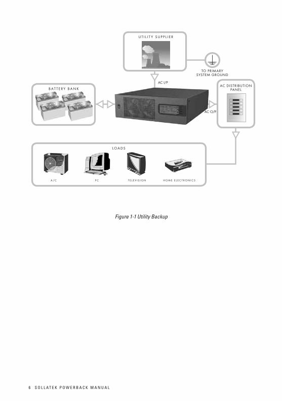
• Utility Backup. see figure 1-1
• renewable energy Source and a Generator, see figure 1-2
consult with your system designer for other possible configurations depending on site or code requirements.
6 S o l l a t e k P o w e r B a c k M a N U a l
Figure 1-1 Utility Backup
B A T T E R Y B A N K
L O A D S
A / C P C T E L E V I S I O N H O M E E L E C T R O N I C S
AC DISTRIBUTION PANEL
U T I L I T Y S U P P L I E R
TO PRIMARY SYSTEM GROUND
AC I/P
AC O/P
S o l l a t e k P o w e r B a c k M a N U a l 7
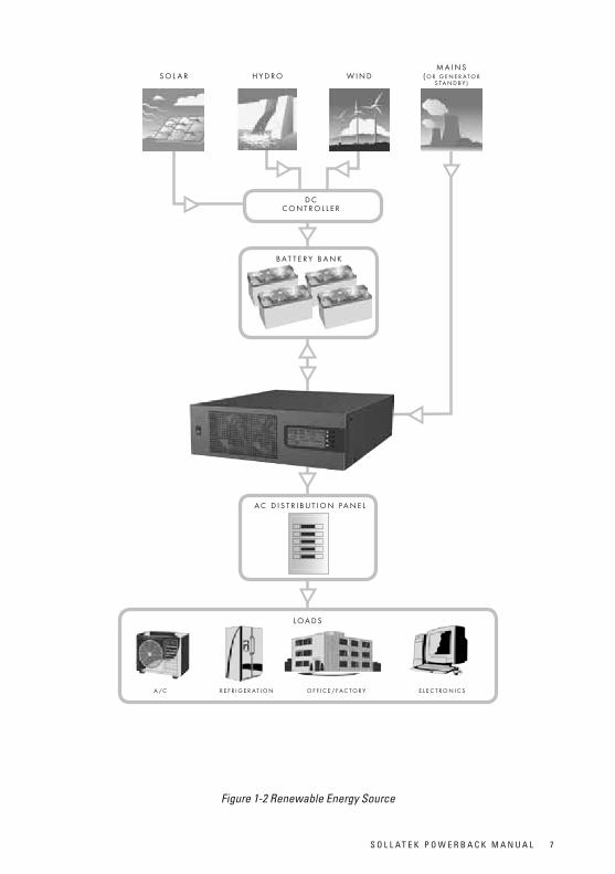
Figure 1-2 Renewable Energy Source
S O L A R H Y D R O W I N D
B A T T E R Y B A N K
L O A D S
A / C R E F R I G E R A T I O N O F F I C E / FA C T O R Y E L E C T R O N I C S
M A I N S ( O R G E N E R A T O R
S T A N D B Y )
D CC O N T R O L L E R
A C D I S T R I B U T I O N PA N E L
the PowerBack PB5000 is able to supply the majority of mains operated domestic and office appliances, including small motors, lights, fans, refrigerators and air conditioners up to a maximum total demand of 5kVa.
Note: In extreme circumstances where the utility supply remains off and the battery back up has expired, appliances such as fridges and air conditioners require approximately 3 minutes restart delay (time is required to balance the refrigerant gas) before utility mains is reinstated . Please contact Sollatek distributors for advice on the Sollatek Voltshield premium range of products.
PositioningofPowerBackandbatterysystem
thePowerbackisdesignedtooperateinarestrictedaccesslocation,lockableandaccessibleonlybycompetentpersons.InstallationmustbeinaccordancewiththerequirementsofIeC60364-4-42.
the PowerBack must be installed in a dry shaded and dust free location with 300mm spacing all round the unit to allow adequate ventilation. the unit has forced cooling and the fans operate full time (Saver mode allow fans to turn off when no load applied)
Batteries must be installed in a dry shaded location. take extra care to ensure there is adequate ventilation to prevent build up of explosive gases (depending on battery type used).
Batteries
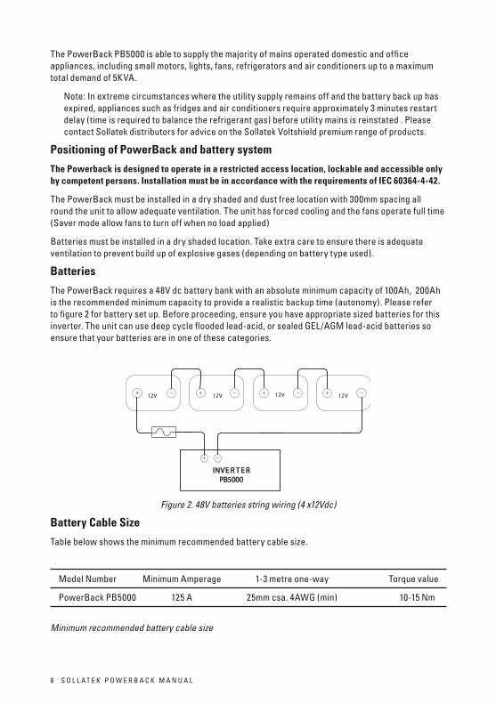
the PowerBack requires a 48V dc battery bank with an absolute minimum capacity of 100ah, 200ah is the recommended minimum capacity to provide a realistic backup time (autonomy). Please refer to figure 2 for battery set up. Before proceeding, ensure you have appropriate sized batteries for this inverter. the unit can use deep cycle flooded lead-acid, or sealed Gel/aGM lead-acid batteries so ensure that your batteries are in one of these categories.
-+-+-+ -+12V 12V 12V 12V
-INVE R T E RPB5000
+ -
Figure 2. 48V batteries string wiring (4 x12Vdc)
BatteryCablesize
table below shows the minimum recommended battery cable size.
Model Number Minimum amperage 1-3 metre one-way torque value
PowerBack PB5000 125 a 25mm csa. 4awG (min) 10-15 Nm
Minimum recommended battery cable size
8 S o l l a t e k P o w e r B a c k M a N U a l
DCDisconnectandover-CurrentProtectionregulations state that battery over-current protection and/or disconnect devices are required. Fuses and disconnects must be correctly sized to protect the Dc cable in use, and must be rated for Dc operation. Do not use devices rated only for ac service – they will not function properly. Note that some installation requirements may not require a disconnect device, although over-current protection is still mandatory. the maximum current drawn from the batteries at the recommended 85% loading is 94adc. Use either cartridge type fuse or appropriately rated McB for Dc use. Fuse rating should always be lower than the amp rating of the battery cable. suggestusingMCB100ACtypeapplicableforDCuse.
BatteryCableConnection
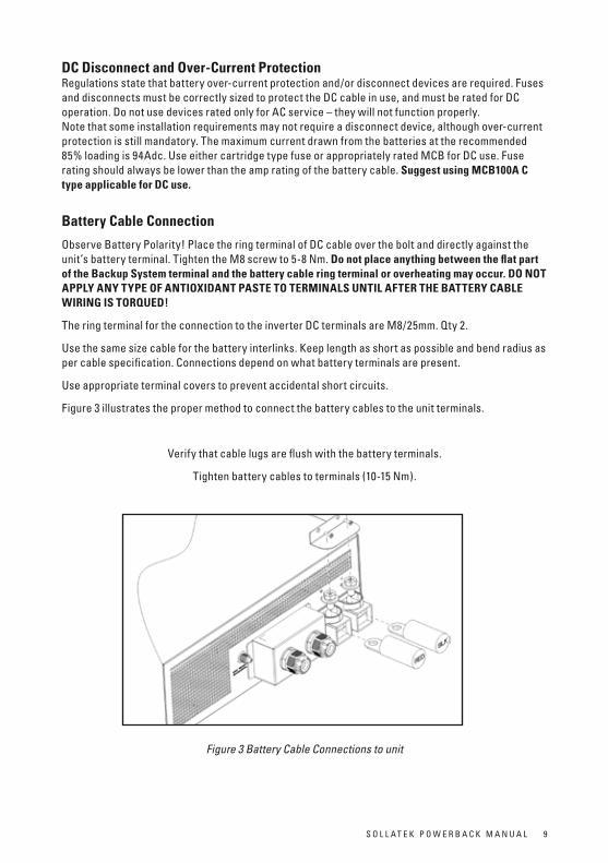
observe Battery Polarity! Place the ring terminal of Dc cable over the bolt and directly against the unit’s battery terminal. tighten the M8 screw to 5-8 Nm. DonotplaceanythingbetweentheflatpartoftheBackupsystemterminalandthebatterycableringterminaloroverheatingmayoccur.DonotAPPLYAnYtYPeoFAntIoXIDAntPAstetoteRMInALsUntILAFteRtHeBAtteRYCABLeWIRInGIstoRQUeD!
the ring terminal for the connection to the inverter Dc terminals are M8/25mm. Qty 2.
Use the same size cable for the battery interlinks. keep length as short as possible and bend radius as per cable specification. connections depend on what battery terminals are present.
Use appropriate terminal covers to prevent accidental short circuits.
Figure 3 illustrates the proper method to connect the battery cables to the unit terminals.
Verify that cable lugs are flush with the battery terminals.
tighten battery cables to terminals (10-15 Nm).
Figure 3 Battery Cable Connections to unit
S o l l a t e k P o w e r B a c k M a N U a l 9
Installationmustonlybecarriedoutbyacompetentperson who has sufficient electrical training and is familiar with safe practices when working on or near electrical systems.
WARnInG:shockHazard.
take appropriate safety measure when dealing with a battery terminal voltage exceeding 40Vdc.
WARnInG:shortcircuithazard.
take special care not to short any battery terminal, shorting of battery terminals will produce large currents and subsequent discharge of molten metals.
Sparks may cause ignition of battery gases if local ventilation is inadequate.
WARnInG:safehandling.
take appropriate safe handling measures when lifting heavy items.
Caution!
Do Not place anything between battery cable ring terminals and terminals on the inverter. the terminal screw is not designed to carry current. apply anti-oxidant paste to terminals aFter terminals have been tightened.
Caution!
ensurethebatteriesstringcircuitisdisconnecteduntilinstructedtodosointhecommissioningprocedure.Bestpracticeistoremovethecablefromthepositiveterminalofthebatteryaswellasoperatingthedisconnectiondevice.
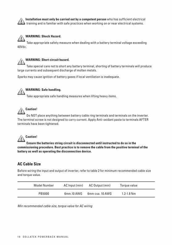
ACCablesize
Before wiring the input and output of inverter, refer to table 2 for minimum recommended cable size and torque value.
Model Number ac Input (min) ac output (min) torque value PB5000 6mm.10 awG 6mm csa. 10 awG 1.2-1.8 Nm
Min recommended cable size, torque value for AC wiring
1 0 S o l l a t e k P o w e r B a c k M a N U a l
S o l l a t e k P o w e r B a c k M a N U a l 1 1
ACConnectionsInstallation should be done by a qualified electrician. consult local regulations for the correct wire sizes, fusing, connectors and conduit requirements. the cable length should be kept to a minimum to prevent excess voltage drop.
the PowerBack is intended for permanent connection (non-pluggable) only. a readily accessible disconnect device (all poles seperation of at least 3mm) shall be incorporated external to this equipment.
the Installer must apply a similar warning label to any remote disconnect device.
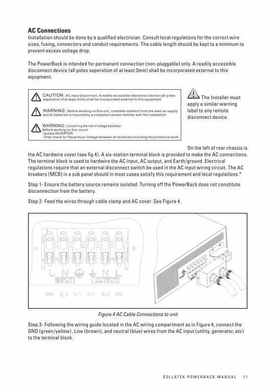
on the left of rear chassis is the ac hardwire cover (see fig 4). a six-station terminal block is provided to make the ac connections. the terminal block is used to hardwire the ac input, ac output, and earth/ground. electrical regulations require that an external disconnect switch be used in the ac input wiring circuit. the ac breakers (McB) in a sub panel should in most cases satisfy this requirement and local regulations.*
Step 1- ensure the battery source remains isolated. turning off the PowerBack does not constitute disconnection from the battery.
Step 2- Feed the wires through cable clamp and ac cover. See Figure 4.
Figure 4 AC Cable Connections to unit
Step 3- Following the wiring guide located in the ac wiring compartment as in Figure 4, connect the GND (green/yellow), line (brown), and neutral (blue) wires from the ac input (utility, generator, etc) to the terminal block.
A
TC-RDW-49-44 2
B
C
D
3
E
F
MECHANICAL
A
B
C
D
E
F
4 765
2 3 4 7651 8
ECN NO.REV.
PHOENIXTEC GROUP
MATERIAL
COATING
DRAW
DESIGN
SAFETY
APPROVED
TITLE
SHEET
UNITS
CHECKEDPART NO.
A4SCALEmm
612-xxxxx-00
PET
NA
1/1
Zhangxin 2011/09/28
1/2
说明:1.材质:2.标签粘贴面为砂纹烤漆3.未注公差: ±0. 2mm
4.印刷清晰,无脏污5.Label must comply with UL approved system PGDQ26.GP等级:GP2P
50# White PET+Matt OPP
CAUTION: AC input disconnect. A readily accessible disconnect device (all-poles separation of at least 3mm) shall be incorporated external to this equipment
WARNING: Before working on this unit, complete isolation from the main ac supply and dc batteries is required by a competent person familiar with the installation.
WARNING:Before working on this circuit-Isolate INVERTER-Then check for Hazardous Voltage between all terminals including the protective earth
Concerning the risk of voltage backfeed
27
.6
82.9
Caution! Be sure that ac source is completely isolated .
Step 4- connect the ac line output wiring to the terminal marked ac line (output) following the wiring guide inside the compartment. connect the ac neutral out to the ac neutral out terminal. connect the output earth to the output earth terminal. ensure the screws in the terminal block are secure.
Step 5- Use the two M3 screws to secure the ac cover.
Step 6-tighten the clamps on the ac cable jackets (not the individual wires) to provide strain relief for the connections.
ACIsolationandovercurrentprotection
the PowerBack has a 40a resettable fuse for internal protection. this fuse is located next to the ac terminals.
*For PerMaNeNtlY coNNecteD eQUIPMeNt a readily accessible disconnect device (all-poles separation of at least 3mm) shall be incorporated external to the equipment.
overcurrent and short circuit protection device must be used to protect the ac mains supply wiring and PowerBack. McB’s 32 or 40a advised depending on cable type selected, installation method and ambient operating temperatures. consult with local regulations.
ACLoads
the ac load or loads must be suitably protected with appropriate fusing according to local regulations.
to ensure calculated battery backup times (autonomy) it is advised to limit the maximum ac loading to 85% measured by the PowerBack lcD indicator :loaD.
ProtectingyourPowerBack
Fittingofvoltageswitcherand/orsurgeprotectiondeviceatmainDBincomer
the PowerBack has limited internal surge protection. to ensure reliable operation installing additional protection at the main DB is recommended.
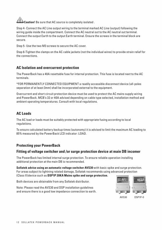
sollatekadviseusinganautomaticvoltageswitcherAVs30 with basic spike and surge protection. For areas subject to lightning related damage, Sollatek recommends using advanced protection (class II)device such as DsP1P20KAMainsspikeandsurgeprotection.
Both devices are obtainable from any Sollatek distributor.
Note: Please read the aVS30 and DSP installation guidelines carefully and ensure there is a good low impedance connection to earth.
1 2 S o l l a t e k P o w e r B a c k M a N U a l
AVS30 DSP1P-0
CommissioningofPowerBackPB5000(systempowerup)
Do not attempt to install or power up the PowerBack unless you are suitably qualified.
ensure install is to local wiring regulations.
ensure terminations and cabling is secure.
ensure the utility and battery supplies are isolated.
ensure PowerBack on/off rocker switch is switched to oFF position.
ensure battery polarity is correct.
ensure there is adequate ventilation for the PowerBack and associated battery bank.
toenergisethePowerBacksystem:
close battery isolator/fuse
Switch on utility mains.
turn power switch to oN. located on front of PowerBack PB5000.
tode-energisethePowerBacksystem:
turn off PowerBack.
Switch off mains.
open battery isolator/fuse
turn on PowerBack for 30 seconds then back off to dissipate any residual power in the inverter.
oPeRAtIon
FrontPanelControlsandLCDIndicators
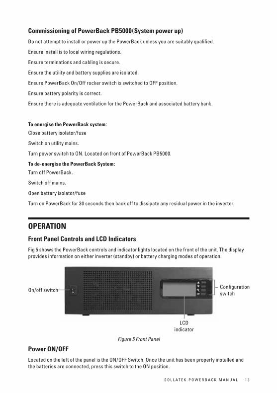
Fig 5 shows the PowerBack controls and indicator lights located on the front of the unit. the display provides information on either inverter (standby) or battery charging modes of operation.
Figure 5 Front Panel
Poweron/oFF
located on the left of the panel is the oN/oFF Switch. once the unit has been properly installed and the batteries are connected, press this switch to the oN position.
S o l l a t e k P o w e r B a c k M a N U a l 1 3
on/off switch configurationswitch
lcD indicator
1 4 S o l l a t e k P o w e r B a c k M a N U a l
Configurationswitch
on the right of panel is the 4 configuration switches which setup unit operation parameters. See table 3 for details.
switch Function Description
up Move up to pre-select
down Move down to pre-select
configuration enter configuration mode, and turn page
enter enter to confirm
Table 3 configuration button function
after you press configuration button and enter configuration mode, there are 4 configuration pages in total. turn page by pressing configuration button.
Page Description selectableoption
1 Input range Normal/generator/wide range
2 output range* 220v/230v/240v
3 Battery type aGM/Gel/FlooDeD
4 charger current** 35a/20a
5 Saver mode oN/oFF
Table 4 configuration button function
*Note: the 220v and 240v output function is reserved for future models. Your PowerBack has a nominal 230V operation only.
**Note: charger current depends on the sourced batteries recommended maximum charge current limit, normally expressed as a percentage of the c20 rate. Your local Sollatek distributor can advise.
S o l l a t e k P o w e r B a c k M a N U a l 1 5
LCDIndicator
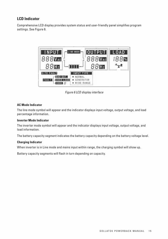
comprehensive lcD display provides system status and user-friendly panel simplifies program settings. See Figure 6.
Figure 6 LCD display interface
ACModeIndicator
the line mode symbol will appear and the indicator displays input voltage, output voltage, and load percentage information.
InverterModeIndicator
the inverter mode symbol will appear and the indicator displays input voltage, output voltage, and load information.
the battery capacity segment indicates the battery capacity depending on the battery voltage level.
ChargingIndicator
when inverter is in line mode and mains input within range, the charging symbol will show up.
Battery capacity segments will flash in turn depending on capacity.
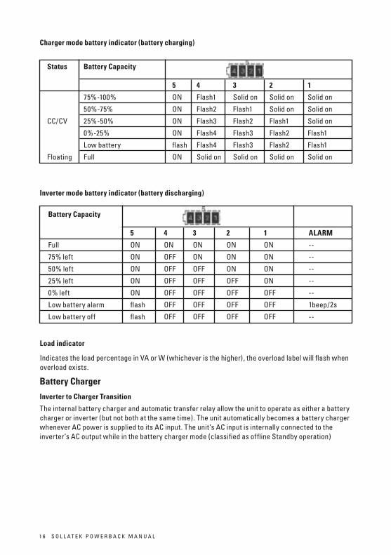
Chargermodebatteryindicator(batterycharging)
status BatteryCapacity 5 4 3 2 1
75%-100% oN Flash1 Solid on Solid on Solid on
50%-75% oN Flash2 Flash1 Solid on Solid on
cc/cV 25%-50% oN Flash3 Flash2 Flash1 Solid on
0%-25% oN Flash4 Flash3 Flash2 Flash1
low battery flash Flash4 Flash3 Flash2 Flash1
Floating Full oN Solid on Solid on Solid on Solid on
Invertermodebatteryindicator(batterydischarging)
BatteryCapacity 5 4 3 2 1 ALARM
Full oN oN oN oN oN --
75% left oN oFF oN oN oN --
50% left oN oFF oFF oN oN --
25% left oN oFF oFF oFF oN --
0% left oN oFF oFF oFF oFF --
low battery alarm flash oFF oFF oFF oFF 1beep/2s
low battery off flash oFF oFF oFF oFF --
Loadindicator
Indicates the load percentage in Va or w (whichever is the higher), the overload label will flash when overload exists.
BatteryCharger
InvertertoChargertransition
the internal battery charger and automatic transfer relay allow the unit to operate as either a battery charger or inverter (but not both at the same time). the unit automatically becomes a battery charger whenever ac power is supplied to its ac input. the unit’s ac input is internally connected to the inverter’s ac output while in the battery charger mode (classified as offline Standby operation)
S o l l a t e k P o w e r B a c k M a N U a l 1 71 6 S o l l a t e k P o w e r B a c k M a N U a l

Chargerterminology
1. ConstantCurrentstage- During this charge cycle, the batteries are charged at a constant current.
2. ConstantVoltagestage- During this charge cycle, the batteries are held at the constant voltage (14.1V/battery aGM&Gel, 14.6v/battery FlooDeD) and accept whatever current (less than the current in cc stage) is required to maintain this voltage. this ensures efficient charging.
3. Floatingstage- During this charge cycle, the batteries are held at the float voltage (13.5V/ battery). If the a/c is reconnected, the charger will reset the cycle as above. If the charge maintains at the float state for 21 days, the charger cycle will then reset.
InternalCircuitBreaker
the unit contains one 40a input circuit breaker located on the rear panel of the chassis adjacent to the ac terminal block. the circuit breaker protects the charger circuit and bypass circuit. the circuit breaker will trip on overload. reset the circuit breaker button after one minute duration.
WorkshopsevicableItems
the PowerBack should only be opened for fuse inspection by an approved Sollatek repair workshop. the fuse details are listed below:
Sollatek Service centre replaceable fuses.
Fc1 to Fc5.
Manufacturer: littlefuse. type: 314030P. rating: F30aH 250V.
S o l l a t e k P o w e r B a c k M a N U a l 1 7
AC lineDisconnect
device
Bypass
Inverter(charger PFC)
Charger
Converter
AC outputto Sub DistributionBoard
Sub DB musthave 2 poleMCB (N+L)
BatteryBank
Disconnectdevice
S o l l a t e k P o w e r B a c k M a N U a l 1 91 8 S o l l a t e k P o w e r B a c k M a N U a l
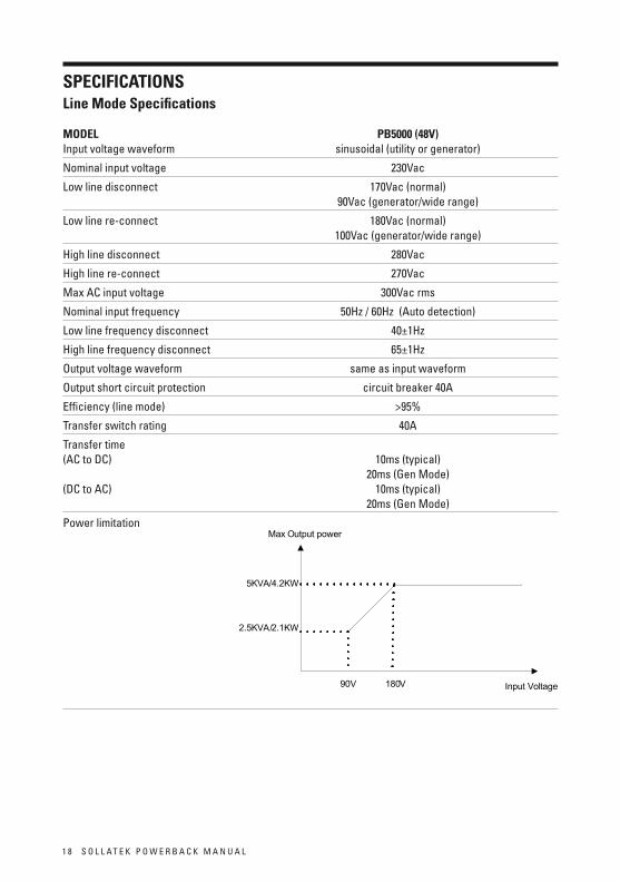
LineModespecificationsMoDeL PB5000(48V)Input voltage waveform sinusoidal (utility or generator)
Nominal input voltage 230Vac
low line disconnect 170Vac (normal) 90Vac (generator/wide range)
low line re-connect 180Vac (normal) 100Vac (generator/wide range)
High line disconnect 280Vac
High line re-connect 270Vac
Max ac input voltage 300Vac rms
Nominal input frequency 50Hz / 60Hz (auto detection)
low line frequency disconnect 40±1Hz
High line frequency disconnect 65±1Hz
output voltage waveform same as input waveform
output short circuit protection circuit breaker 40a
efficiency (line mode) >95%
transfer switch rating 40a
transfer time (ac to Dc) 10ms (typical) 20ms (Gen Mode) (Dc to ac) 10ms (typical) 20ms (Gen Mode)
Power limitation
sPeCIFICAtIons
Input Voltage
Max Output power
5KVA/4.2KW
2.5KVA/2.1KW
90V 180V
S o l l a t e k P o w e r B a c k M a N U a l 1 9
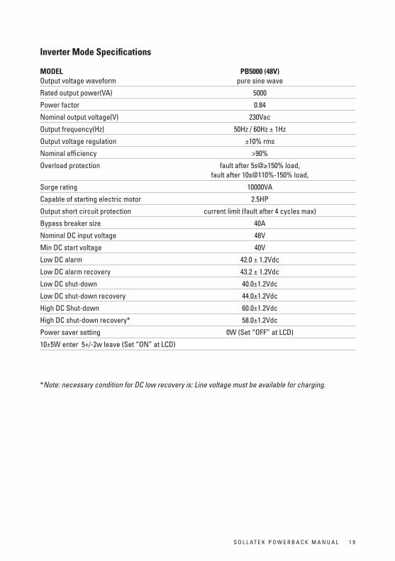
InverterModespecifications MoDeL PB5000(48V)output voltage waveform pure sine wave
rated output power(Va) 5000
Power factor 0.84
Nominal output voltage(V) 230Vac
output frequency(Hz) 50Hz / 60Hz ± 1Hz
output voltage regulation ±10% rms
Nominal efficiency >90%
overload protection fault after 5s@≥150% load, fault after 10s@110%-150% load,
Surge rating 10000Va
capable of starting electric motor 2.5HP
output short circuit protection current limit (fault after 4 cycles max)
Bypass breaker size 40a
Nominal Dc input voltage 48V
Min Dc start voltage 40V
low Dc alarm 42.0 ± 1.2Vdc
low Dc alarm recovery 43.2 ± 1.2Vdc
low Dc shut-down 40.0±1.2Vdc
low Dc shut-down recovery 44.0±1.2Vdc
High Dc Shut-down 60.0±1.2Vdc
High Dc shut-down recovery* 58.0±1.2Vdc
Power saver setting 0w (Set “oFF” at lcD)
10±5w enter 5+/-2w leave (Set “oN” at lcD)
*Note: necessary condition for DC low recovery is: Line voltage must be available for charging.

2 0 S o l l a t e k P o w e r B a c k M a N U a l
ChargeModespecifications MoDeL PB5000(48V) Nominal input voltage 230Vac
Input voltage range 180V- 270Vac(Normal range)
100V- 270Vac(generator/wide range)
Nominal output voltage according to the battery type
Nominal charge current 20a(95-175v,gen/wide,only), 35a(175-275v)@35a setting 20a(175v-275v)@20a setting)
Battery initial voltage(sps setup) >35Vdc
charger short circuit protection Unit shutdown automatic
over charge protection Bat. V ≥60Vdc, Fault, Buzzer alarm
charge algorithm three stage: Boost cc (constant current stage) › Boost cV (constant voltage stage) › Float (constant voltage stage)
Battery type Setting(±0.3v/bat) Boost cc/cV Float Battery type Voltage(V) Voltage(V) 48 48 Flooded 58.4 53.6 aGM/Gel 56.4 54
Generalspecifications
Safety certification ce(eN60950)
eMI classification eN62040-2, claSS a
operating temperature range 0°c to 45°c
Storage temperature -15°c - 60°c
altitude, operational elevation: 0 - 1500 Meters
relative humidity 5% to 95% non-condensing
audible Noise 60dB max
cooling Forced air, variable speed fan
Dimension 350mm w *110mm H *407mm D
Net weight 9kG
S o l l a t e k P o w e r B a c k M a N U a l 2 1
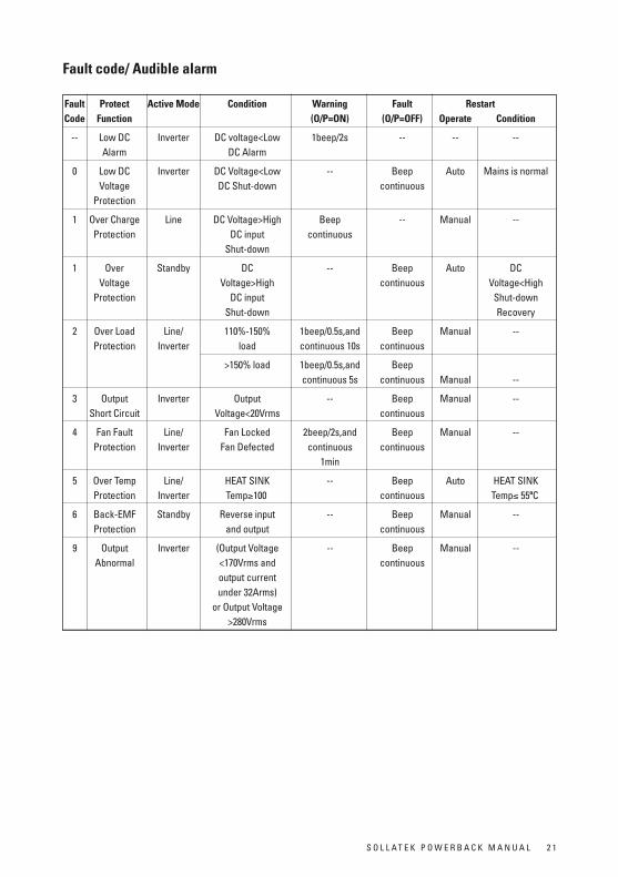
Faultcode/Audiblealarm
Fault Protect ActiveMode Condition Warning Fault RestartCode Function (o/P=on) (o/P=oFF) operate Condition
-- low Dc Inverter Dc voltage<low 1beep/2s -- -- -- alarm Dc alarm
0 low Dc Inverter Dc Voltage<low -- Beep auto Mains is normal Voltage Dc Shut-down continuous Protection
1 over charge line Dc Voltage>High Beep -- Manual -- Protection Dc input continuous Shut-down
1 over Standby Dc -- Beep auto Dc Voltage Voltage>High continuous Voltage<High Protection Dc input Shut-down Shut-down recovery
2 over load line/ 110%-150% 1beep/0.5s,and Beep Manual -- Protection Inverter load continuous 10s continuous
>150% load 1beep/0.5s,and Beep continuous 5s continuous Manual --
3 output Inverter output -- Beep Manual -- Short circuit Voltage<20Vrms continuous
4 Fan Fault line/ Fan locked 2beep/2s,and Beep Manual -- Protection Inverter Fan Defected continuous continuous 1min
5 over temp line/ Heat SINk -- Beep auto Heat SINk Protection Inverter temp≥100 continuous temp≤ 55ºc
6 Back-eMF Standby reverse input -- Beep Manual -- Protection and output continuous
9 output Inverter (output Voltage -- Beep Manual -- abnormal <170Vrms and continuous output current under 32arms) or output Voltage >280Vrms
2 2 S o l l a t e k P o w e r B a c k M a N U a l
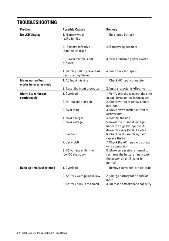
Problem PossibleCauses Remedy
noLCDdisplay 1. Battery weak 1. re-charge battery <35V for 48V 2. Battery defective 2. Battery replacement (can't be charged) 3. Power switch is not 3. Press and hold power switch pressed 4. Battery polarity reversed, 4. Send back for repair can’t start up the unit
Mainsnormalbut 1. ac Input missing 1. check ac input connection worksininvertermode 2. reset the input protector 2. Input protector is effective
Alarmbuzzerbeeps 1. overload 1. Verify that the load matches the continuously capability specified in the specs 2. output short circuit 2. check wiring or remove abnor- mal load 3. over temp 3. Move away barrier in front of airflow inlet 4. over charger 4. restart the unit 5. over voltage 5. lower the Dc input voltage under the high Dc input shut- down recovery (58.0±1.2Vdc) 6. Fan fault 6. check vents are clear, if not replace the fan 7. Back-eMF 7. check the ac Input and output wire connection 8. Dc voltage under the 8. Make sure mains is normal to low Dc shut-down recharge the battery if not switch the power off until mains is normal
Backuptimeisshortened 1. overload 1. remove some non-critical load 2. Battery voltage is too low 2. charge battery for 8 hours or more 3. Battery bank is too small 3. Increase battery bank capacity
tRoUBLesHootInG
S o l l a t e k P o w e r B a c k M a N U a l 2 3
seRVICInGoFPoWeRBACK
thePowerBackcontainsnouser-serviceableparts.
Do not attempt to open or repair your Sollatek PowerBack. warranty will be void.
Please contact your local Sollatek distributor for advice.
www.sollatek.com
Guarantee
Sollatek (Uk) ltd guarantee that if within 2 years of purchase this appliance fails due to faulty workmanship or materials we will repair or replace it free of charge provided that:
• the appliance has been correctly installed and used within the electrical range as specified on the appliance nameplate. • the appliance has been used in accordance with the operating instructions.• there has been no attempt to open the appliance for any reason whatsoever.• the appliance is returned to Sollatek or a Sollatek agent in good condition.• Sollatek shall not be liable under the terms of this guarantee for any material fault or damage as a result of failure of this appliance.• this guarantee does not affect your statutory or common law rights.
Returns
Should your unit need repair, the quickest and simplest way is to return it to your dealer or to a Sollatek Service centre or direct to the nearest Sollatek office.
IMPoRtAnt: Before returning a appliance to a Sollatek Service centre, contact the returns department to obtain a returns number. You will be asked for the following information which you should have ready:
Your name, address, telephone, fax (If available), email (If available)Date purchased, where purchasedSerial number, model numberlocal voltage and type of load.Description of fault
once you have the returns number, ensure that the unit is securely packed enclosing a short note with details as above and mark the unit clearly with the returns number. remember also to add your name and address. complying with the above will ensure that your unit will be treated promptly and efficiently. without a returns number it will not be possible to trace a unit or check progress of repair of the unit.
Sollatek (UK) Ltd
Unit 10 Poyle 14
Newlands drive,
Poyle, Slough SL3 0DX,
United Kingdom.
Tel:
International: +44 1753 688300
National: 01753 688300
Fax:
International: +44 1753 685306
National: 01753 685306
E-mail:
Internet:
www.sollatek.com
All weights and dimensions are approximate.Specifications are subject to change without prior notice.
©Sollatek (UK) Limited 2011. All Rights Reserved.
SOLLATEK and the SOLLATEK device are the trade marks of the Sollatek group of companies. www.sollatek.com
ISO9001: 2008 accredited company
Sollatek provides you with full back up support and a two year worldwide warranty on all products, with local support in over twenty countries worldwide.
P R O VIDING
CLE
AN
RELIABLE POW
ER
WO
RLD
WID E
PowerBack PB5000 Manual October 11
A/I: 10910152
t h e p o w e r t o p r o t e c t
Warranty
Sollatek’s warranty covers the Sollatek unit only and not any other equipment connected to it. Sollatek will not accept any consequential loss or damage to any equipment connected to it directly or indirectly.
the warranty will only be honoured if the Sollatek unit has been used properly and not been tampered with. the warranty is strictly on return to base at the expense of the owner. In certain circumstances, Sollatek may offer to return the repaired unit back to the owner.
the warranty will be void if warranty Seal (where applicable) is broken or the unit has been opened or tampered with. the warranty obligation does not cover any additional charges the owner may incur as a result of the unit needing repair or being sent back to an authorised service centre or a Sollatek workshop.
Caution: opening a Sollatek unit may impair its function and render it inoperable. only experienced Sollatek technicians can service the unit.


![215988-001MD Power Supply -48Vdc +Bias Tee - servsat.comservsat.com/_pdfs/Mitec 215988-001MD_Rev_0_ pwr supply -48Vdc+Bias Te.[1].pdf · The module is a stand-alone Power Supply +](https://img.pdfslide.us/doc/110x75/5d34231f88c993b7748b9a23/215988-001md-power-supply-48vdc-bias-tee-215988-001mdrev0-pwr-supply-48vdcbias.jpg)