Embed Size (px)
Citation preview

The University of AkronIdeaExchange@UAkronWilliams Honors College, Honors ResearchProjects
The Dr. Gary B. and Pamela S. Williams HonorsCollege
Spring 2019
Power Wheelchair CanopyMohamed F. BattahThe University of Akron, [email protected]
Joshua D. BrownThe University of Akron, [email protected]
Dujuan J. McClendonThe University of Akron, [email protected]
Gavin M. FranciscoThe University of Akron, [email protected]
Please take a moment to share how this work helps you through this survey. Your feedback will beimportant as we plan further development of our repository.Follow this and additional works at: https://ideaexchange.uakron.edu/honors_research_projects
Part of the Computer-Aided Engineering and Design Commons, Electro-Mechanical SystemsCommons, and the Manufacturing Commons
This Honors Research Project is brought to you for free and open access by The Dr. Gary B. and Pamela S. WilliamsHonors College at IdeaExchange@UAkron, the institutional repository of The University of Akron in Akron, Ohio,USA. It has been accepted for inclusion in Williams Honors College, Honors Research Projects by an authorizedadministrator of IdeaExchange@UAkron. For more information, please contact [email protected],[email protected].
Recommended CitationBattah, Mohamed F.; Brown, Joshua D.; McClendon, Dujuan J.; and Francisco, Gavin M., "Power WheelchairCanopy" (2019). Williams Honors College, Honors Research Projects. 991.https://ideaexchange.uakron.edu/honors_research_projects/991

Power Wheelchair Canopy
Authors:
Joshua Brown…. Conceptual Design / CAD / Part Design and Tolerancing
Dujuan McClendon…. Conceptual Design / Mechanisms Assembly / Circuitry /
Purchasing / Design
Mohamed Battah…. Conceptual Design / CAD / Design
Gavin Francisco…. Builder / Conceptual Design /Purchasing/Design
Advisors:
Dr. Gopal Nadkarni
Mechanical Engineering
The University of Akron
Spring, 2019

Table of Contents
Chapter 1: Introduction 2
1.1 Background 2
1.2 Product Definition 3
Chapter 2: Conceptual Design 4
Chapter 3: Embodiment Design Error! Bookmark not defined.
Chapter 4: Detail Design 0
Chapter 5: Discussion Error! Bookmark not defined.
Chapter 6: Conclusions Error! Bookmark not defined.
References 0
Chapter 1: Introduction
1.1 Background
Some power wheelchair users can not drive and independently hold an umbrella
at the time because they do not have much upper body strength. Therefore, users are
unprotected from the rain and are getting soaking wet. One of the members of this
group is in a wheelchair and faces this problem. He has previously searched for
something to protect him from rain, but could not found something he could
independently use. What users need is a powered umbrella that attaches to their power
wheelchair. There is no such umbrella available in the market. In this project, the
solution to this problem will be designed and built in the form of an umbrella for his
wheelchair.
Exploration of various methods of rain protect will be explored. Calculations will
be performed to verify that everything will work when assembled. The prototype will
then be built. Assuming there will be some issues, as there always seem to be, several
iterations of the prototype will be built. This is assuming that there will still be money left
in the budget to complete these other iterations. It is also desired to make it
inexpensive. This will allow power wheelchair users all over the world to purchase it for
themselves. In order to achieve this, the project will lean heavily on the 3-D printing
capabilities that the University of Akron has to offer.

1.2 Product Definition
Due to Mohamed’s disability he is incapable of carrying a normal umbrella
because he does not have much upper body strength. Knowing and understanding this
problem, yields possibility for a solution. As a group project, a power wheelchair
mounted umbrella system, will be designed and constructed. There are no umbrellas in
the market that mount directly to power wheelchairs, therefore our design has to. It also
has to be detachable so when it is not raining it can be removed and for easy
transportation. A requirement that Mohamed put into place was that it needs to be
button actuated, with the button requiring little to no force to press. It is also required
that this umbrella system fit through doorways. It will be lightweight and compact for
easy transport, but strong enough to withstand wind and heavy rain. It will also need to
be easily manufacturable, which will be taken into consideration during the design
stages.
Our design is a rectangular box, mounted to a steel post and connected to a
power wheelchair, housing a roller of waterproof material, 2 spools, 2 batteries, 2
rotating motors, and part of the outer most tube of a set of 3 telescoping tubes on each
end.
The way it works is rotating spools powered by motors wind wires, run through a
set of 3 telescoping tubes on each end of the box, in one direction to telescope the
tubes out of each other and unroll the material through a slit in the box. The other
direction telescopes the tubes into each other and rolls the material through the slit in

the box. This is happening while the end of the roller of material is attached to end of
the inner most telescoping tube on each end of the box.

Chapter 2: Conceptual Design
To begin the conceptual design process, each group member began researching
the current market to find existing designs of power wheelchair umbrellas and to find
ideas and opportunities for improvement. Internet searches were conducted to find
products that could accomplish our task and to find out how certain features could help
our own design as well as quickly show us which features would not help our design.
Much information was gathered by each group member before the group met for a
brainstorming session. During brainstorming, each member presented as many new or
modified concepts as possible and these ideas were filtered and improved throughout
the discussion. The ideas developed from brainstorming were then narrowed down to
four different concepts. Concept sketches were created for each of the ideas

.
Figure 1 Hand Drawn Sketches
The group then began identifying and defining design criteria by which the
concepts will be evaluated to break down the ideal design into several categories that
could be looked at individually so that the ideas could be compared easily. These
design criteria were then assigned weighting factors to indicate the importance to the
design as evaluated by the group. The value of each category was easily determined
since one of the group members is the target consumer for this product. An objective
tree was created to display the importance of each criteria.

Table 1 Design Criteria Definitions
Design Criteria Definition
Material Cost How much do all the needed components cost.
Durability Ability to withstand heavy rain and strong winds.
Transportability How easy it is to transport when detached from the power wheelchair.
Operation How easy it is to use.
Reliability Ability to consistently perform its function.
Safety Do any of the components cause harm.
Figure 2 Design Criteria Objective Tree

The objective tree was used to create a weighted decision matrix to evaluate
competing concepts by rating the design criteria with weighting factors and scoring the
degree to which each design concept meets the criteria. A scale from 1-5 with five being
excellent and 1 being poor was used. This made comparing the different concepts into a
more quantitative process instead of a qualitative one. The weighted decision matrix
weighted the scores so that the most important criteria had a stronger effect on the
overall score. Based on the total scores of each concept in the weighted decision
matrix, the group determined that the awning concept was the best design to continue
to work on and improve.

Table 2 Weighted Decision Matrix
Umbrella Baby Carriage
Weighting Factor Score Rating Score Rating Score Rating Score Rating
0.4 2 0.8 3 1.2 5 2 2 0.8
0.12 3 0.36 2 0.24 1 0.12 5 0.6
0.064 2 0.128 3 0.192 4 0.256 0 0
0.096 5 0.48 2 0.192 1 0.096 3 0.288
0.12 5 0.6 4 0.48 1 0.12 2 0.24
0.2 3 0.6 3 0.6 1 0.2 4 0.8
1 2.968 2.904 2.792 2.728
Flip CanopyAwning
Table 3 Reasoning Behind Weighted Decision Matrix
Durability The baby carriage concept was given the best durability rating but the awning concept also scored fairly well because of the fixed supports.
Transportabilty
Operation
Reliability
The umbrella concept was given the highest score because it would be the easiest to attach and detach.
The awning concept got the best score for operation because it could be a one button opertion.
The awning and flip canopy recieved the best reliability scores because we believe they would be the most successful.
The umbrella concept is the least safe due to the size necessary to achieve the task.
It would require a diameter of at least 6 feet so this would be way to large for practical use.
we'd be able to adapt a premade umbrella to the design. The other concepts were about the same.
Material Cost
Safety
The Umbrella concept was determined to have the cheapest material costs because
Chapter 3: Embodiment Design
The next step in the design process was to select a single design concept and
begin to develop and improve it. Based on the results of our conceptual design stage,
the awning concept was selected to be further developed. The group began working to
create the product architecture that would successfully and efficiently carry out the
functions required by the design. We started by identifying the different functions that
would need to be accomplished during the operation of the product. Through the
continuous improvement of the idea, we found a technique that would allow us to use
simple tube and string to telescope the arms of the awning covering from a short
collapsed length to the final extended length. Using this technique, we were able to
develop a design that would involve the awning covering to collapse to a smaller size
when it was not in use and still extend to the full covering length required to fully protect
the consumer from the rain. The physical components of the design began being
identified and a sketch was created to show how they would be configured with respect
to each other in the design.

Figure 3 Collapsible Awning Concept Sketch

It was determined that the covering would be attached to telescoping tubes, so it
extends and collapses the covering. These telescoping tubes would be powered using a
rotating motor and an attached spool to adjust the speed of the extension. The motor
would be driven by a simple switch that will be able to rotate the motor clockwise,
counter clockwise, and stop rotation. Since the covering itself will not be a rigid body, a
pull down blind will be used as the covering material in order to utilize the spring loaded
system involved in drawing the blind. This spring system would make the covering roll
up for easy storage during collapsing as well as keep the covering taught at all times
during operation. All of these components wil=[ be stored in a simple enclosed box that
would be suspended above the user’s head by a support beam. A function structure
diagram was created to show the function each component has on the design. A
schematic diagram was created to explain the operation of the design. There are
several Solidworks drawings that show the configuration of the components in relation
to each other. There are also pictures that show the roller mechanism and the switch
wiring.

Figure 4 Function Structure Diagram

Figure 5 Extended Canopy Schematic Diagram
Figure 6 Collapsed Canopy Schematic Diagram
Press and hold switch in
one direction.
Bateries power
motors.
Motor shafts rotate.
Spools rotate.
Wires unwind.
Tubes telescope
out of each
other.
Material is
unrolled.
Press and hold switch in
the direction.
Bateries power
motors.
Motor shafts
rotate in opposite direction.
Spools rotate in opposite direction.
Wires wind in
opposite direction.
Tubes telescope into each
other.
Material is rolled.

Figure 7 Left Side View Drawing

Figure 8 Inside of Box View Drawing

Figure 9 Top View Drawing

Figure 10 Bottom View Drawing

Figure 11 Roller
Figure 12 Switch

Chapter 4: Detail Design
After embodiment and conceptual designs were completed, the detailed design
stage began. Parts began to be chosen and outsourced to places that could produce
them. Parts that needed custom manufacturing such as the mounts, brackets,
fasteners, and other similar parts, were 3-D modeled and then 3-D printed. Due to the
nature of 3-D printing, detailed 2-D part drawings are not required, thanks to the
capabilities of the machine. The use of 3-D printing was crucial in prototyping, due to its
cost efficiency.
Early on the big question was posed, “how will this assembly mount to the
wheelchair”. The main mounting joint had to fit inside of a bracket, that was on the
existing wheelchair. It was then tightened down using a screw mechanism that was pre-
existent on the chair. This was where it was chosen to be attached, as it was an easy,
and stable, mounting position. The mount will be a ¾ inch thin walled metal rod and a
custom 3-D printed joint, to reduce weight. This will allow the rod to fit tightly, in order to
reduce the assembly from moving or swaying when the chair is in motion.
The next part that had issues were the telescoping tubes. The strings inside that
drive them, had much more friction than what was intended. This would require a high
torque motor to run. It was also desired to run it at a reasonable speed, to allow the
canopy to be extended quickly. In order to complete both of these tasks in conjunction,
a high torque motor was selected and a spool to wind the string was 3-D printed. This
spool was given a much larger diameter than originally intended, to allow an increase in
speed. The diameter that was determined to be sufficient was 3 inches. With a 20 RPM

high torque motor and the 3 inch diameter spool, the calculated time for full extension
would be close to 9 seconds. This was determined by Mohamed to be an acceptable
speed. The spool was 3-D printed using ABS. Unfortunately, during the building process
some issue arose. The box became too congested with the addition of the larger spool.
The team made a quick decision to 3-D print a smaller spool and order a motor with a
higher RPM. With a 100 RPM high torque motor and the 2.75 inch diameter spool, the
calculated time for full extension was close to 3.5 seconds.
Figure 13 Spool
A 5” x 5” x 36” box was built and assembled to hold all the components. The box
was made out of very durable, yet lightweight wood. Flex Seal was purchased in order
to waterproof this wood. Sizing was measured and all components fit nicely in the box,
after the addition of the downsized spool and relocating the motors to be mount on the
bottom of the box, through use of separate motor compartments. These separate motor
compartments were specifically designed to free up space inside of the box, while giving
a more secure mounting point for the motors. Another effect that was gained was wiring
protection. The soldered wires were now secure from outside elements.

Figure 14 Motor to Outside of Box Mount
Over the course of the build, many types and sizes of mounting brackets were
required. These brackets included; inside PVC mounts, outside PVC mounts, inside
bottom mount, outside bottom mounts, motor mounts, and the main mounting joint. All
mounts were 3-D printed with ABS, to allow for quick turnaround time as well as being
an inexpensive material, given the lack of funding.
Figure 15 Rod to Outside of Box Mount

Figure 16 Tube to Outside of Box Mount
Figure 17 Tube to Inside of Box Mount

Figure 18 Wheelchair to Rod Mount

In total the assembly required 10 components to be 3-D printed including: (2)
PVC tube to inside of box mounts, (2) PVC tube to outside of box mounts, (1) rod to
outside of box mount, (1) wheelchair to rod mount, (2) spools, and (2) motor to box
mounts. It also required (1) thin walled metal rod, (3) sizes of PVC (¾”, ½”, and ¼”), (1)
spool of monofilament fishing line, (2) 6V batteries, (1) switch, (1) enclosure box, (2)
motors, and some wiring.
As far as dimensions for components goes, all dimensions were measured,
rather than being calculated. All components have to fit into a confined area of an
already existing body, therefore measurements are a better way to figure out
dimensions, than calculations would be. Two 3-D models show the assembly and
exploded assembly on the next page followed by a bill of materials and total cost of the
materials. The following pages show Solidworks drawings with dimensions for all the
components. Due to advisor instruction, the whole project was designed and built prior
to 3-D modelling. All models were created as the project proceeded, and therefore, any
issues that arose were solved in the same manor.

Figure 19 Assembly
Figure 20 Exploded Assembly

Table 4 Bill of Materials
Parts Number Needed Cost Per Part ($) Source
0.25" X 3' pvc tube 1 1.00$ Home Depot
0.5" X 3' pvc tube 1 2.00$ Home Depot
0.75" X 3' pvc tube 1 2.50$ Home Depot
Steel Bar (0.75" OD x 24") 1 8.00$ Home Depot
Wood Box (30"X 5"X 5") 1 7.00$ Home Depot
Roller (1" ODx30") 1 5.00$ Walmart
Switch 1 10.00$ Amazon
Wiring N/A N/A N/A
Motor (RC motor) 2 12.00$ Amazon
String for the motor N/A N/A N/A
Batteries 2 6.00$ Amazon
Screws, Nuts, Washers, Lock WashersN/A 15.00$ Home Depot
Flex Seal 1 12.00$ Home Depot
Total cost 80.50$
Bill of Materials

Figure 21 0.25 Inch PVC Tube Drawing

Figure 22 0.50 Inch PVC Tube Drawing

Figure 23 0.75 Inch PVC Tube Drawing

Figure 24 Box Drawing

Figure 25 Spool Drawing

Figure 26 Tube to Inside of Box Mount Drawing

Figure 27 Tube to Outside of Box Mount Drawing
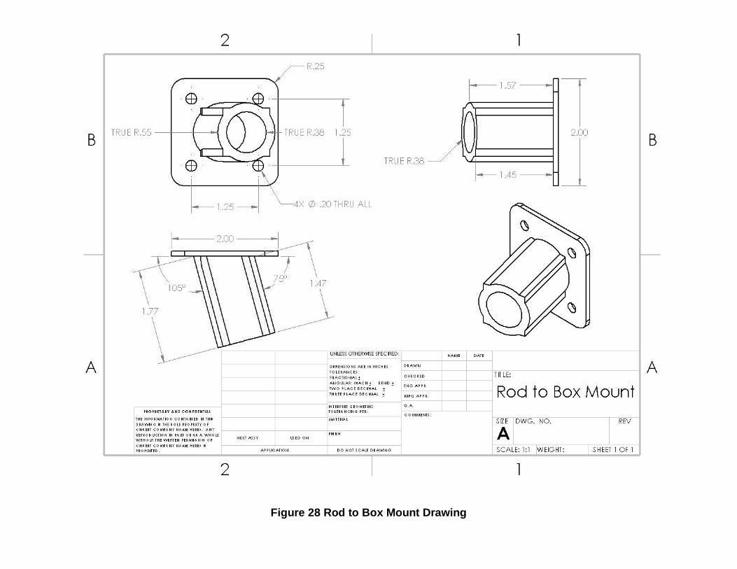
Figure 28 Rod to Box Mount Drawing

Figure 29 Wheelchair to Rod Mount Drawing

Figure 30 Motor to Box Mount Drawing

Figure 31 Assembled View Drawing

Figure 32 Exploded View Drawing

Chapter 5: Discussion
Over the course of the first semester, the group was able to thoroughly
brainstorm ideas and identify a clear design for the project. The design continued to
improve with each meeting and was steadily developing. All of the components required
to construct a rough prototype were identified and acquired. During this semester, a 3D
model of the design was developed to use as a blueprint for actual construction. This
will help in the precise placement and sizing of components to avoid interferences and
other small problems that may occur during the first prototype production. After all the
placement of the components are determined, the group built the first prototype. The
group hoped to make several irritations of the prototype, but due to a lack of funding we
were unable. Also Mohamed was injured and out for two weeks and got a new power
wheelchair. This delayed the ability to redesign the wheelchair to rod mount to work with
new power wheelchair. Since we had time for only one prototype we did everything we
could to identify the problems in our telescoping mechanism in the prototype and fix it.
Chapter 6: Conclusions
The absence of easily accessible weather protection is a struggle that many
power wheelchair users face on a daily basis. This device could ideally allow power
wheelchair users the capability of operating this canopy independently. It will allow for
individuals incapable of opening and supporting an umbrella a safe and easy to use
alternative.
Unfortunately, our first prototype was unsuccessful. The main issue was that the
motors were not strong enough to telescope the tubes out. The springs in the blind want
to roll up in the opposite direction. This resistance plus friction from the fishing line was
too much for the motors handle. Another issue was the fishing line was falling of the
spool and had to be rewind.
This project involved knowledge gained through our combined 19 years of
mechanical engineering schooling at the University of Akron. For example, Solidworks
was used to model several different pieces and parts that were then sent to be 3-D
printed. Several of the parts had to be redesigned and reprinted after troubleshooting
resulted in some unforeseen issues we had not considered.
If given adequate time and funds our group strongly believes that this product
could be taken to market. If so, it could potentially be sold as a wheelchair accessory
that could help many people. With a few mounting modifications this product could be
used with a variety of different power wheelchairs.
After completing the first prototype, our group has several ideas for possible
improvements. For example; it would be beneficial to decrease the overall weight of the

product as it will allow for better operation and safer conditions. A few ways to
accomplish this could be a different selection of materials as well as mounting the 6V
batteries to the wheelchair itself rather than inside the box. Another potential
improvement to the design would be the conversion of telescoping through the use of
wires, spools, and motors to telescoping through hydraulics. Hydraulics would eliminate
many of the problems we have encountered with this type of design and greatly
increase manufacturing capabilities. Therefore, if we were to attempt to take this to
market, it would be in our best interested to redesign the system to use hydraulics.

References
https://www.youtube.com/watch?v=KK_ebAdOiRw
https://www.youtube.com/watch?v=oS4VuXM0SGc&authuser=0
https://www.youtube.com/watch?v=yInMEfrQWwA