Embed Size (px)
Citation preview
The University of AkronIdeaExchange@UAkron
Honors Research Projects The Dr. Gary B. and Pamela S. Williams HonorsCollege
Spring 2017
Lawn Mower LiftRandall E. SchelcherThe University of Akron, [email protected]
Please take a moment to share how this work helps you through this survey. Your feedback will beimportant as we plan further development of our repository.Follow this and additional works at: http://ideaexchange.uakron.edu/honors_research_projects
Part of the Applied Mechanics Commons
This Honors Research Project is brought to you for free and open access by The Dr. Gary B. and Pamela S. WilliamsHonors College at IdeaExchange@UAkron, the institutional repository of The University of Akron in Akron, Ohio,USA. It has been accepted for inclusion in Honors Research Projects by an authorized administrator ofIdeaExchange@UAkron. For more information, please contact [email protected], [email protected].
Recommended CitationSchelcher, Randall E., "Lawn Mower Lift" (2017). Honors Research Projects. 461.http://ideaexchange.uakron.edu/honors_research_projects/461
Lawn Mower Lift
Randall Schelcher: Report, 3D Model, Hand Sketches, Calculations
Brandon Lockhart: Report, 3D Model, Charts, Calculations Kody Teets: Report, Charts
Advisors: Dr. Sawyer
Mechanical Engineering Department University of Akron
Spring 2017
1

2
Randall Schelcher
Brandon Lockhart
Kody Teets
3
Executive Summary
Our team of engineers were given the task of coming up with a design project
and designing the system, creating calculations, and brainstorming ideas. We set out to
design a riding lawn mower lift. The purpose of this design was to assist in general
maintenance like replacing blades, oil changes, etc.
To accomplish this task, our team started to brainstorm ideas and make sketches
to look at all the options. We then did research and looked at different size lawn
mowers and looked at the specifications. This helped our team to be able to design the
size of platform needed to accommodate the size of the tractors. Then, calculations
were performed to see the lifting power needed for the mower. Once all of the
decisions and calculations were made, we designed the 3D model of our design.
As a result, our team of engineers have produced a lawn mower lift concept that
is both functional and user friendly. This will help the customer have a more functional
and more ergonomically friendly design to work on any repairs. We designed the lift to
have the front end lift up significantly more than the back end so the user can change
blades on a mower easier. Also the user could make the front and back end level to get
under the vehicle to change oil or perform general maintenance with more room to work
with under the vehicle. Once the concept was developed, we expanded our capabilities
to other small motorized vehicles with four wheels, like four-wheelers, go-carts, or
side-by-sides.
4
Table of Contents Executive Summary 3
Table of Contents 4
Introduction 5 Background 5 Simple Design Brief 5 Expanded Design Brief 6 Product Description 7
Conceptual Design 7 Free Hand Sketches of Concept Design 9 Analyzed Proposed Solutions 10 Weighted Decision Matrix 11
Embodiment Design 12 Calculations 13 Safety Factor 14 Assembly drawings/part drawings 16 Figure 3 - Assembly Drawing (Top View) 16 Figure 4 - Assembly Drawing (Side View) 17
Discussion 17
Conclusion 18
References 19
Appendices 20
5
Introduction
Our team of engineers began the process of designing a lawn mower lift by
looking at many angles and different product range. Our team began to look at what
products are available in the market and how we could design a lift to best suit customer
needs in a cost and performance perspective. The goal of our lawn mower lift is to be
able to lift the front end of the mower to be able to change the blades on the mower.
Our team of engineers also decided that lifting the back end of the mower up a little bit
would make it ergonomically better on the user.
Background
Our team is very hands-on and wanted to design something that would actually
be useful. Car lifts are common, but what about the people that like working on smaller
vehicles like lawn mowers and four-wheelers? We set out to make a simple and
affordable but also practical lift to make this type of work easier. I believe if the lift works
and is actually manufactured, we would all enjoy having it as another tool in the garage.
Because the project had somewhat of a practical use to us, it made the work more
interesting.
Simple Design Brief
Our team came up with an idea to create a lawn mower lift and make it
ergonomically friendly for the user, make is safe, and make the product cost effective.
6
The system level of design must be made with safety in mind and satisfy criteria of
customers.
Expanded Design Brief
Our design must take multiple factors into consideration. One of the biggest
factors is how to lift the mower up in the front and in the back. Our team is weighing the
decisions for the front lift to be a winch, a pulley, or a come-along. Also, the back lift is
another decision needing to be made, the team is looking at options such as, no lift, low
profile bottle jack, floor jack, and a winch. The size of the overall lift needs to be taken
into consideration. Our team thinks the lift should not be too large but we also believe
we want it to be a reasonable size for a larger product range and not specific to one.
With having the front and back end lift up, the user can easily level the vehicle out and
get underneath the vehicle to change oil. The front lift will have the vehicle lift
approximately three foot off of the platform. The back platform will lift the mower up
about fifteen inches. This will put the vehicle at an angle for easier maintenance.
We then have discussed amongst ourselves to figure out what we want our final
output of the overall system. This includes how easy it will be to lift and lower the
mower. The platform is also designed to accommodate for different types of mowers
not just one brand specific. As the design phase went on, our team of engineers also
realized that the lift could be used for a larger product range. The lift could be used for
four wheelers, side-by-side, and go-carts. We also looked into the mobility of the overall
7
product, we designed the product that if need be could fit into the back of a truck and be
hauled around.
Product Description
The desired lawn mower lift will have a platform of four foot by eight foot. This
will help accommodate a large range of products. Also, with making the product to
those restrictions, it will be able to fit reasonably well in the bed of a truck to be mobile.
The winch will need to lift a weight of approximately 600 pounds. The winch selected is
rated at a load of 2000 pounds. The back end platform will have a jack under it that can
accommodate up to 4000 pounds, so that will be sufficient in lifting a mower or vehicle
on the platform. Using all of these products, this will make this mechanism durable,
safe, and user friendly. The design of this product can also be modified to be able to
change for other types of small motor vehicles.
Conceptual Design
After evaluating customer needs, our team of engineers began brainstorming
concept solutions of how to lay out the design of our lawn mower lift. Our first task we
had to consider was how to get the lawn mower onto our actual device. We decided
that the best option was to drive the lawn mower onto the lift. Another function was how
do we lift the lawn mower up into the air. This included idea such as a winch, a jack, a
pulley system, and a come-along, Then we needed to decide if we had a winch, how
we would power the winch. Our options included, a battery, a wall outlet, or manually
8
crank the winch. Next we looked at the type of material we would want to make our lift
out of to make sure we have a sturdy enough lift. Different materials could include
aluminum, steel, stainless steel, or plastic. Finally, we wanted to look at different ways
to fasten the material together. We looked at either welding or fastening with bolts.
After brainstorming all of these different solutions for each function of our lift, a
morphological chart will be constructed to help organize all of the ideas.
Morphological Chart
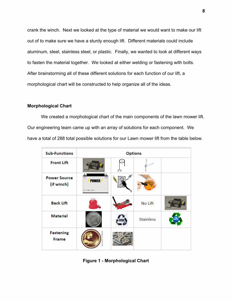
We created a morphological chart of the main components of the lawn mower lift.
Our engineering team came up with an array of solutions for each component. We
have a total of 288 total possible solutions for our Lawn mower lift from the table below.
Figure 1 - Morphological Chart
9
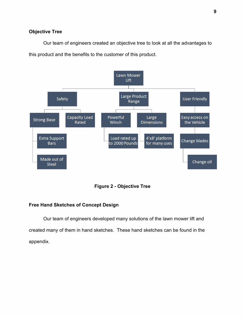
Objective Tree
Our team of engineers created an objective tree to look at all the advantages to
this product and the benefits to the customer of this product.
Figure 2 - Objective Tree
Free Hand Sketches of Concept Design
Our team of engineers developed many solutions of the lawn mower lift and
created many of them in hand sketches. These hand sketches can be found in the
appendix.
10
Analyzed Proposed Solutions
Using solution screening techniques, our team of engineers was able to begin to
eliminate some possible solutions found through our beginning brainstorming
techniques. This was done to narrow down a final solution better. We ruled out a pulley
system on the lift due to concerns of the pulley not being strong enough. We neglected
a wall outlet for the concerns of a mobile lift. There is not always a power source around
and neglected the hand crank because of the manual labor intensity it would need to
crank it. We decided for the system that the back would need to lift up too so the option
of no lift is ruled out. Also, with winch would not be feasible and a normal floor jack
would not be needed. We also decided that the best material for the lift would be a
stronger material and decided on steel. In this stage of the design, we started to narrow
down our design to just three options.
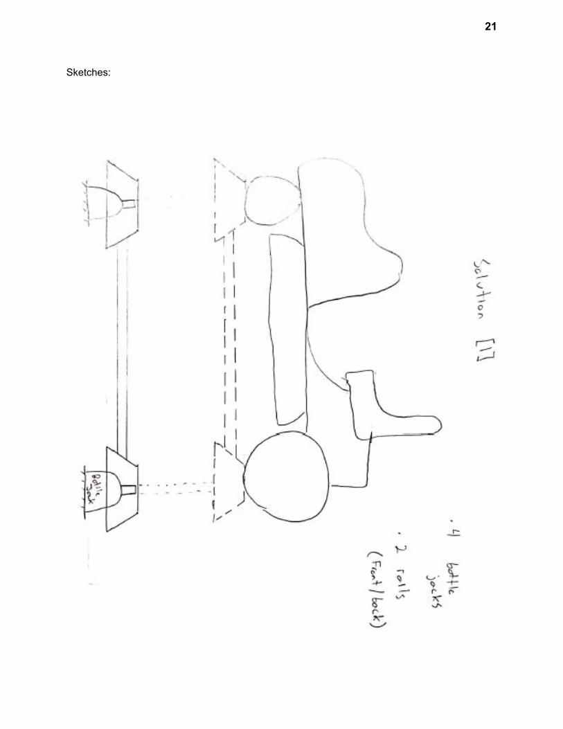
Solution 1: Our first design consisted of two ramps, one for the front tires and one for
the back, they would be connected by square tubing and have 4 bottle jacks (one under
each tire connected to raise the same amounts. This design used guides to ensure the
ramps went up stable and straight.
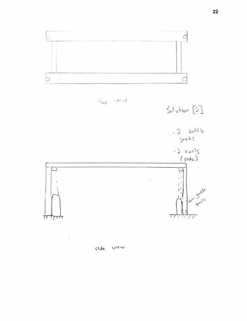
Solution 2: Our second design was similar to the first, with the exception that each side
would have its own rail. This made it a little easier to go to two jacks, but made it harder
to get under the lawn mower which is the problem we are trying to solve.
11
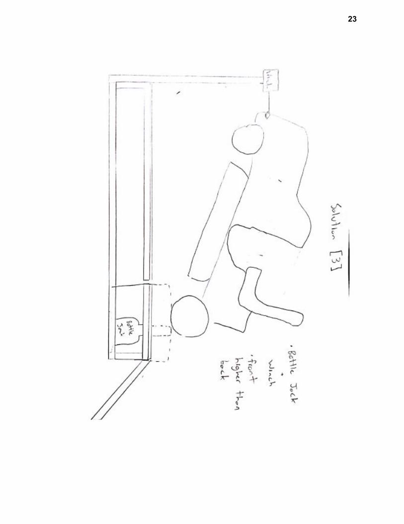
Solution 3: Our last design, was to lift the back of the tractor up a little, and then use a
winch to raise the front to desired level this would allow even more access to the bottom
of the machine and is structurally safer, in that it can’t fall off the rails. This is th design
we are going to use. Although we are not using the first two designs, we have and may
continue to steal ideas from them for improvements and modifications.
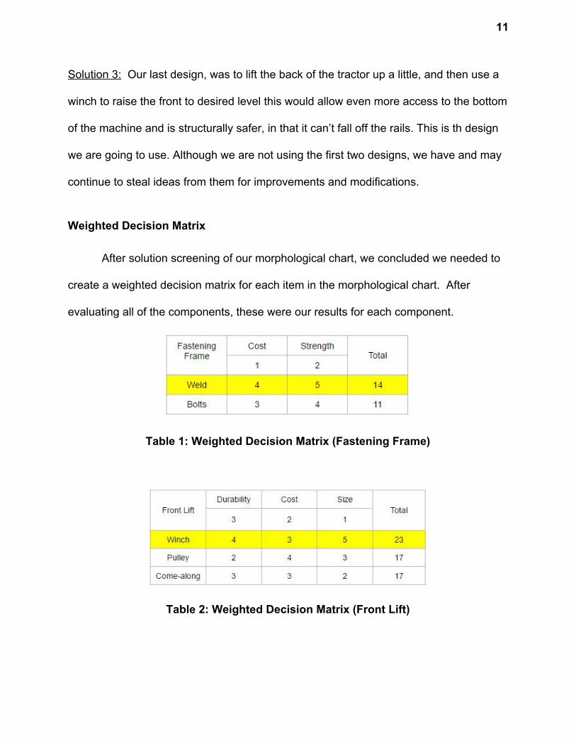
Weighted Decision Matrix
After solution screening of our morphological chart, we concluded we needed to
create a weighted decision matrix for each item in the morphological chart. After
evaluating all of the components, these were our results for each component.
Table 1: Weighted Decision Matrix (Fastening Frame)
Table 2: Weighted Decision Matrix (Front Lift)
12
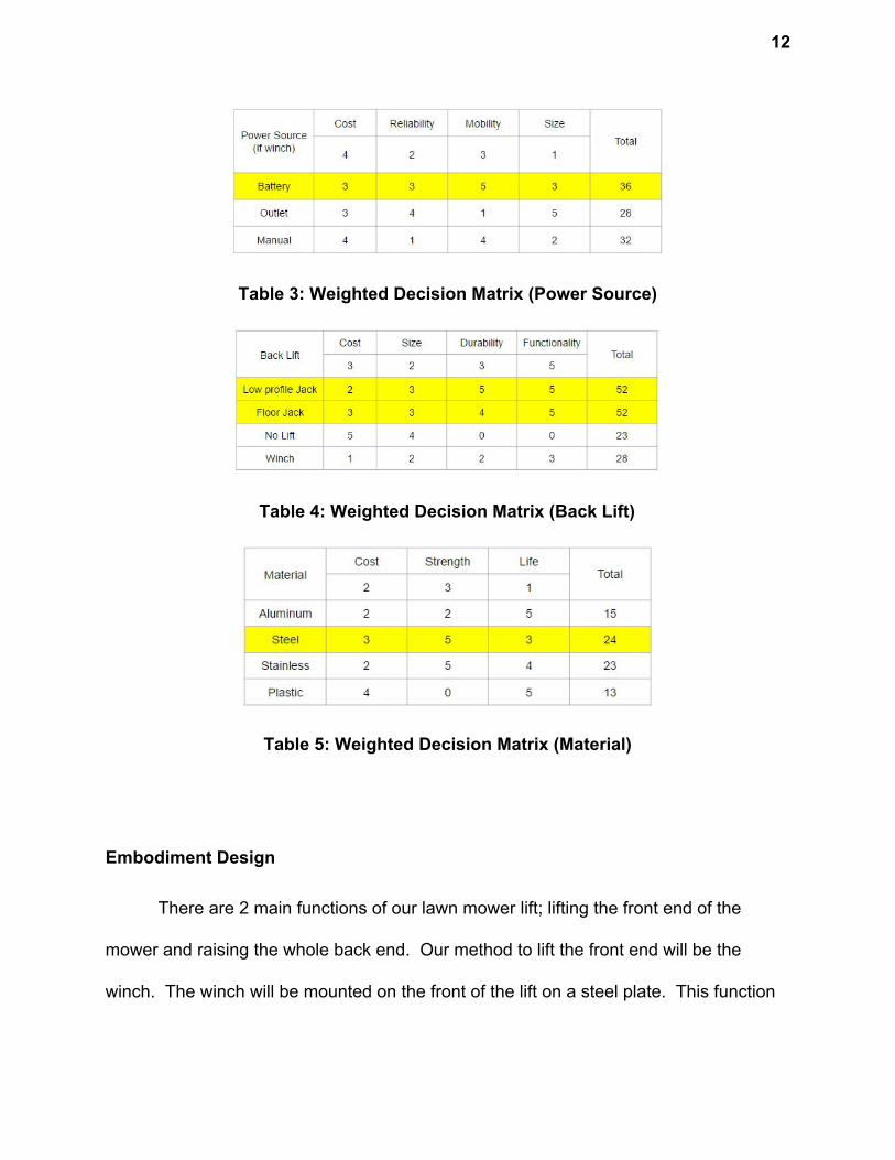
Table 3: Weighted Decision Matrix (Power Source)
Table 4: Weighted Decision Matrix (Back Lift)
Table 5: Weighted Decision Matrix (Material)
Embodiment Design
There are 2 main functions of our lawn mower lift; lifting the front end of the
mower and raising the whole back end. Our method to lift the front end will be the
winch. The winch will be mounted on the front of the lift on a steel plate. This function
13
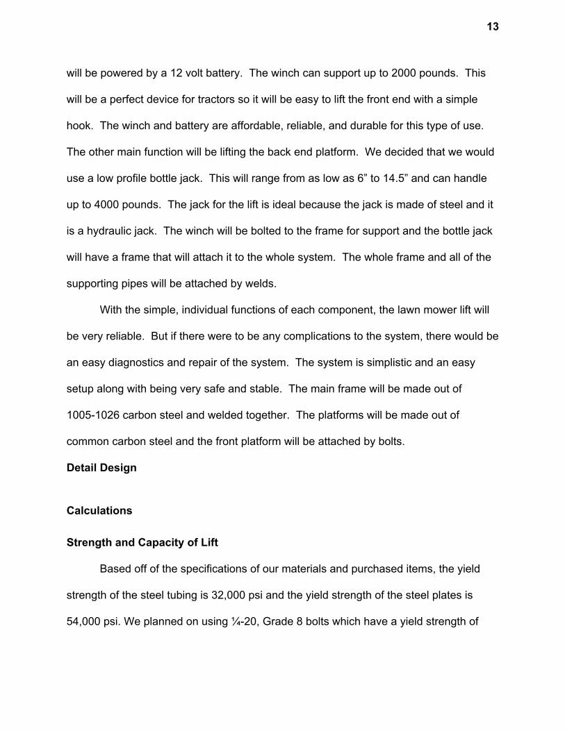
will be powered by a 12 volt battery. The winch can support up to 2000 pounds. This
will be a perfect device for tractors so it will be easy to lift the front end with a simple
hook. The winch and battery are affordable, reliable, and durable for this type of use.
The other main function will be lifting the back end platform. We decided that we would
use a low profile bottle jack. This will range from as low as 6” to 14.5” and can handle
up to 4000 pounds. The jack for the lift is ideal because the jack is made of steel and it
is a hydraulic jack. The winch will be bolted to the frame for support and the bottle jack
will have a frame that will attach it to the whole system. The whole frame and all of the
supporting pipes will be attached by welds.
With the simple, individual functions of each component, the lawn mower lift will
be very reliable. But if there were to be any complications to the system, there would be
an easy diagnostics and repair of the system. The system is simplistic and an easy
setup along with being very safe and stable. The main frame will be made out of
1005-1026 carbon steel and welded together. The platforms will be made out of
common carbon steel and the front platform will be attached by bolts.
Detail Design
Calculations
Strength and Capacity of Lift
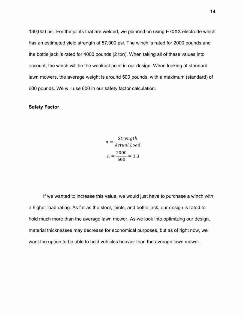
Based off of the specifications of our materials and purchased items, the yield
strength of the steel tubing is 32,000 psi and the yield strength of the steel plates is
54,000 psi. We planned on using ¼-20, Grade 8 bolts which have a yield strength of
14
130,000 psi. For the joints that are welded, we planned on using E70XX electrode which
has an estimated yield strength of 57,000 psi. The winch is rated for 2000 pounds and
the bottle jack is rated for 4000 pounds (2 ton). When taking all of these values into
account, the winch will be the weakest point in our design. When looking at standard
lawn mowers, the average weight is around 500 pounds, with a maximum (standard) of
600 pounds. We will use 600 in our safety factor calculation.
Safety Factor
If we wanted to increase this value, we would just have to purchase a winch with
a higher load rating. As far as the steel, joints, and bottle jack, our design is rated to
hold much more than the average lawn mower. As we look into optimizing our design,
material thicknesses may decrease for economical purposes, but as of right now, we
want the option to be able to hold vehicles heavier than the average lawn mower.
15
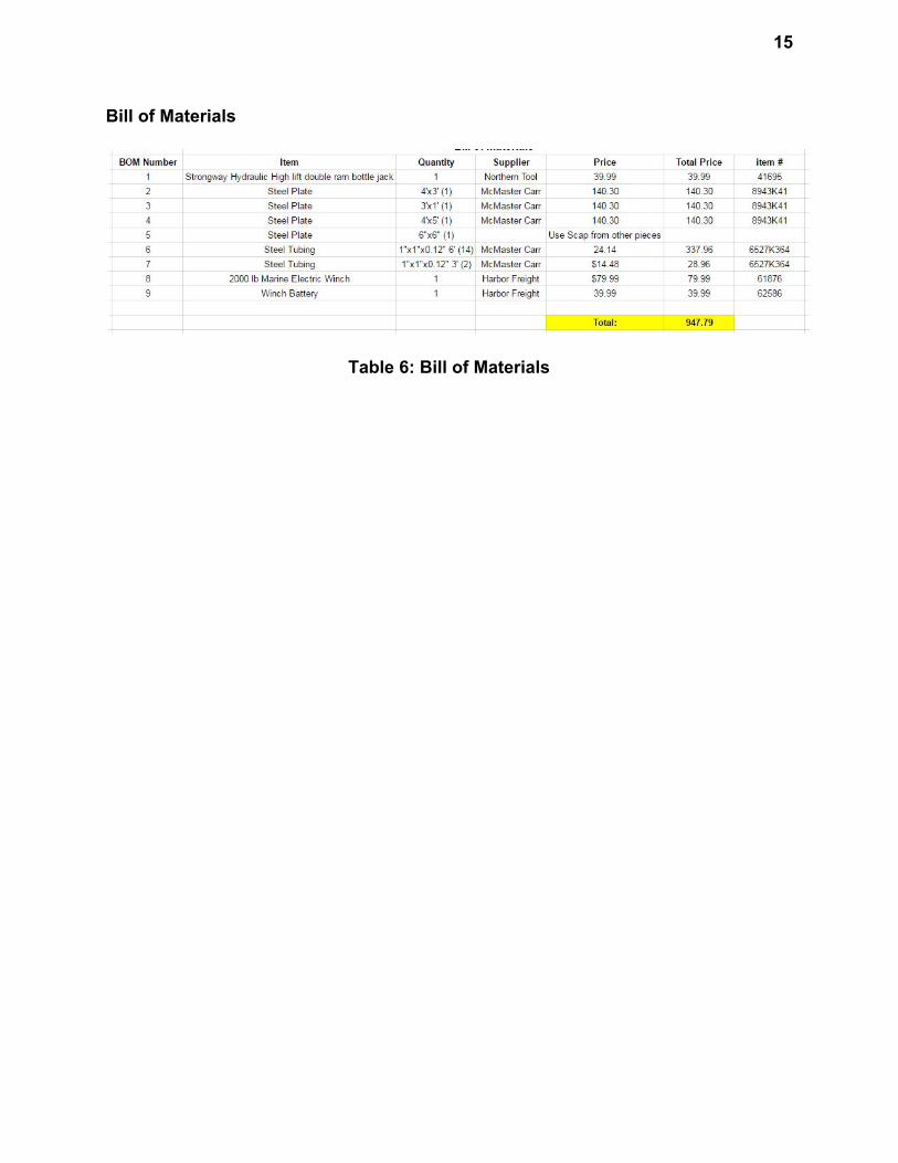
Bill of Materials
Table 6: Bill of Materials
16
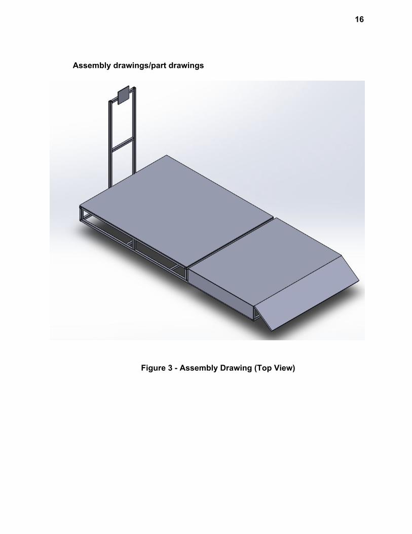
Assembly drawings/part drawings
Figure 3 - Assembly Drawing (Top View)
17
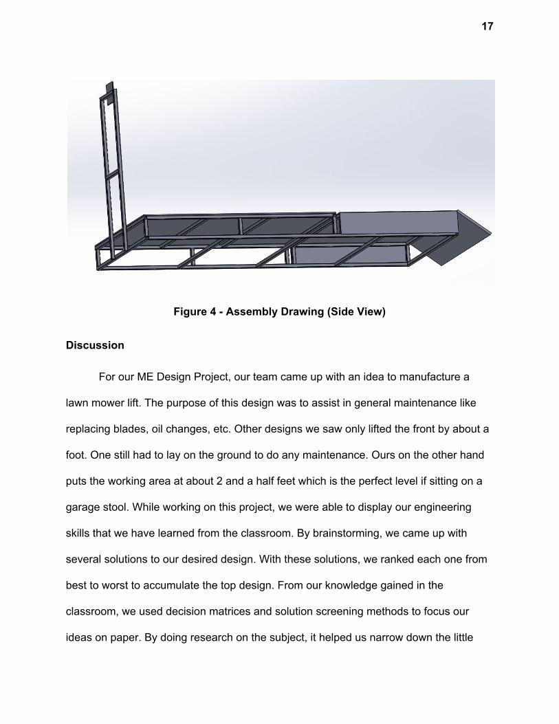
Figure 4 - Assembly Drawing (Side View)
Discussion
For our ME Design Project, our team came up with an idea to manufacture a
lawn mower lift. The purpose of this design was to assist in general maintenance like
replacing blades, oil changes, etc. Other designs we saw only lifted the front by about a
foot. One still had to lay on the ground to do any maintenance. Ours on the other hand
puts the working area at about 2 and a half feet which is the perfect level if sitting on a
garage stool. While working on this project, we were able to display our engineering
skills that we have learned from the classroom. By brainstorming, we came up with
several solutions to our desired design. With these solutions, we ranked each one from
best to worst to accumulate the top design. From our knowledge gained in the
classroom, we used decision matrices and solution screening methods to focus our
ideas on paper. By doing research on the subject, it helped us narrow down the little
18
details to construct our fully developed design. Using the methods mentioned earlier, a
prototype drawing of our lawn mower lift design was generated. We genuinely believe
that this product may have a chance in the market place. In our decision making of
going with this final design, it was determined that this product will be easy to use,
extremely reliable, and cost friendly. Hopefully, The University of Akron will be able to
grant us with the money needed in able to construct the prototype product. This will help
us visualize possible drawbacks/designs of our system. In conclusion, this project was
very helpful in exposing us to a variety of tools to provide solutions for the customers in
our future careers.
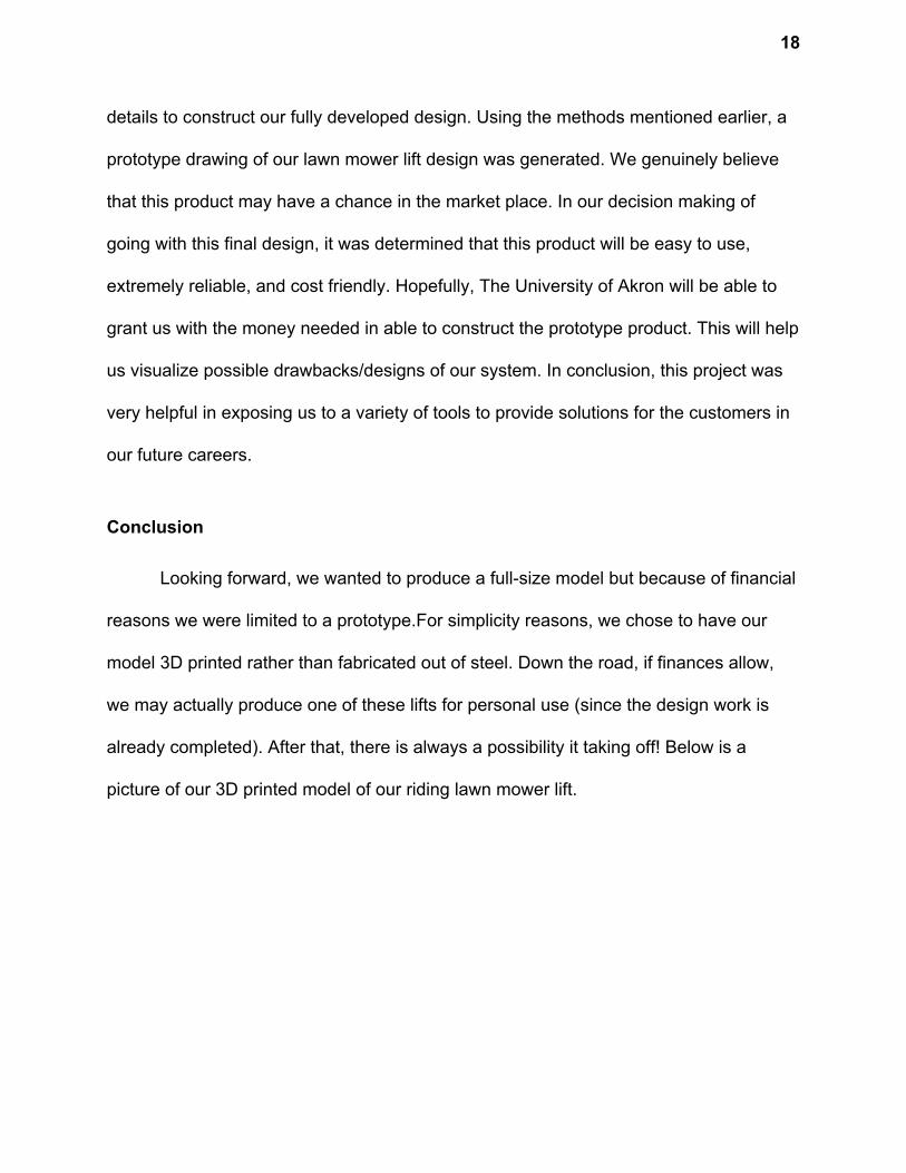
Conclusion
Looking forward, we wanted to produce a full-size model but because of financial
reasons we were limited to a prototype.For simplicity reasons, we chose to have our
model 3D printed rather than fabricated out of steel. Down the road, if finances allow,
we may actually produce one of these lifts for personal use (since the design work is
already completed). After that, there is always a possibility it taking off! Below is a
picture of our 3D printed model of our riding lawn mower lift.
19
Figure 5 - Prototype (3D Printed Model)
References
"McMaster-Carr." McMaster-Carr. N.p., n.d. Web. 14 Dec. 2016.
20
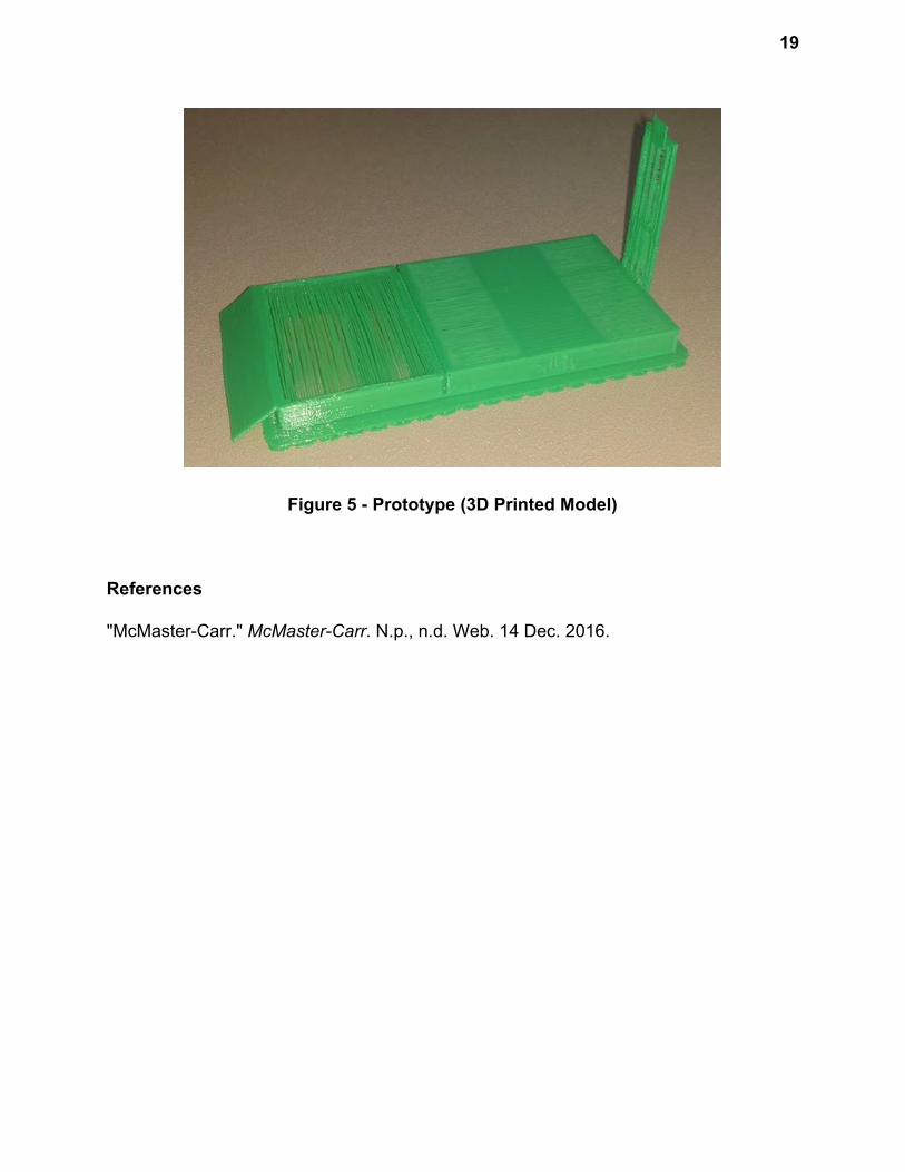
Appendices
Updated Timeline:
Tractor Specifications:
21
Sketches:
22
23