Embed Size (px)
Citation preview
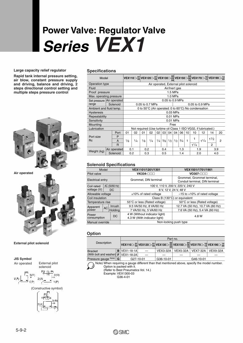
Specifications
Power Valve: Regulator Valve
Series VEX1
Solenoid Specifications
Large capacity relief regulator
Rapid tank internal pressure setting, air blow, constant pressure supply and driving, balance and driving, 2 steps directional control setting and multiple steps pressure control
Operation type
Model VEX110�- 0102
Fluid Air/Inert gas1.5 MPa1.0 MPa
0.05 to 0.9 MPa0.05 to 0.7 MPa 0.05 to 0.9 MPa0 to 50°C (Air operated: 0 to 60°C) No condensation
0.03 MPa0.01 MPa0.01 MPa
FreeNot required (Use turbine oil Class 1 ISO VG32, if lubricated.)
Air operated, External pilot solenoid
Proof pressureMax. operating pressureSet pressure range
Air operatedSolenoid
Air operatedSolenoid
Ambient and fluid temp.HysteresisRepeatabilitySensitivityMountingLubrication
01PortPAR
Port sizeRc
Weight (kg)
VEX120�- 0102 VEX130�-
020304
040610
VEX150�- VEX170�-1012 VEX190�-14
20
1 8
02
1 4
01
1 8
02
1 4
10
1
11 4
11 4
12
0.10.2
0.20.3
0.40.5
1.31.4
1.92.0
02
1 4
03
3 8
04
1 2
04
1 2
06
3 4
10
1
14
2
11 2
20
2
3.94.0
Pilot valveModel
Electrical entry
100 V, 110 V, 200 V, 220 V, 240 V6 V, 12 V, 24 V, 48 V
±10% of rated voltage
VEX1101/1201/1301 VEX1501/1701/1901VK334-��� VO307-���
Grommet, DlN terminalGrommet, Grommet terminal,Conduit terminal, DIN terminal
–15 to +10% of rated voltage
55°C or less (Rated voltage) 50°C or less (Rated voltage)9.5 VA/50 Hz, 8 VA/60 Hz 12.7 VA (50 Hz), 10.7 VA (60 Hz)7 VA/50 Hz, 5 VA/60 Hz 7.6 VA (50 Hz), 5.4 VA (60 Hz)
4 W (Without indicator light) 4.3 W (With indicator light) 4.8 W
Class B (130°C) or equivalent
Non-locking push type
Coil ratedvoltage (V)
AC (50/60 Hz)DC
Allowable voltageCoil insulationTemperature rise
Apparent power
Power consumption
Manual override
ACInrush
Holding
DC
Option
Bracket(With bolt and washer)
DescriptionVEX110�- 01
02
VEX3-32A VEX5-32A VEX7-32A VEX9-32A—VEX1-18-1A—
G27-10-01—
G36-10-01
Part no.
— —G46-10-01
—VEX1-18-2APressure gauge Note)
BFG
VEX120�- 0102 VEX130�-
020304
040610
VEX150�- VEX170�- 1012 VEX190�- 14
20
Note) When requiring a gauge different than that mentioned above, specify the model number.Option is packed with it.(Refer to Best Pneumatics Vol. 14.)Example: VEX1300-03
G36-4-01
Air operated
External pilot solenoid
JIS SymbolAir operated External pilot
solenoid
(Constructive symbol)
5-9-2
VEX
Option
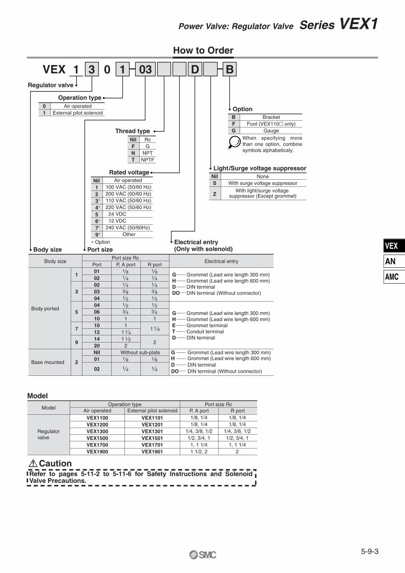
1 03 D31 0 B
Operation type
Regulator valve
Thread type
Light/Surge voltage suppressor
∗ Option
Rated voltage
When specifying more than one option, combine symbols alphabeticaly.
Body size Electrical entry
Body ported
Base mounted
Body size Port sizeElectrical entry (Only with solenoid)
Port01
102
Port size Rc P, A port R port
1 8 1 81 4 1 4
107
1214
920 2
Without sub-plate
2
1 41 2
023 03
1 4 1 43 8 3 8
04 1 2
045 06
1 23 4
10 11
11 41
1
1 23 4
1
1 2
Nil
2 01 1 8 1 8
02 1 4 1 4
G Grommet (Lead wire length 300 mm)H Grommet (Lead wire length 600 mm)D DIN terminalDO DIN terminal (Without connector)
G Grommet (Lead wire length 300 mm)
G Grommet (Lead wire length 300 mm)Grommet (Lead wire length 600 mm)DIN terminalDIN terminal (Without connector)
HDDO
H Grommet (Lead wire length 600 mm)E Grommet terminalT Conduit terminalD DIN terminal
Model
Model
Regulatorvalve
Operation typeAir operated External pilot solenoid P, A port
Port size RcR port
VEX1100 VEX1101VEX1200VEX1300VEX1500VEX1700VEX1900
VEX1201VEX1301VEX1501VEX1701VEX1901
Caution
How to Order
1/8, 1/41/8, 1/4
1/4, 3/8, 1/21/2, 3/4, 1
1, 1 1/41 1/2, 2
1/8, 1/41/8, 1/4
1/4, 3/8, 1/21/2, 3/4, 1
1, 1 1/42
01
Air operatedExternal pilot solenoid
NilS
Z
NoneWith surge voltage suppressor
With light/surge voltage suppressor (Except grommet)
BFG
BracketFoot (VEX110� only)
Gauge
NilFNT
RcG
NPTNPTF
Nil123∗
4∗
56∗
7∗
9∗
Air operated100 VAC (50/60 Hz)200 VAC (50/60 Hz)110 VAC (50/60 Hz)220 VAC (50/60 Hz) 24 VDC 12 VDC240 VAC (50/60Hz) Other
Refer to pages 5-11-2 to 5-11-6 for Safety Instructions and Solenoid Valve Precautions.
5-9-3
Power Valve: Regulator Valve Series VEX1
VEX
AN
AMC
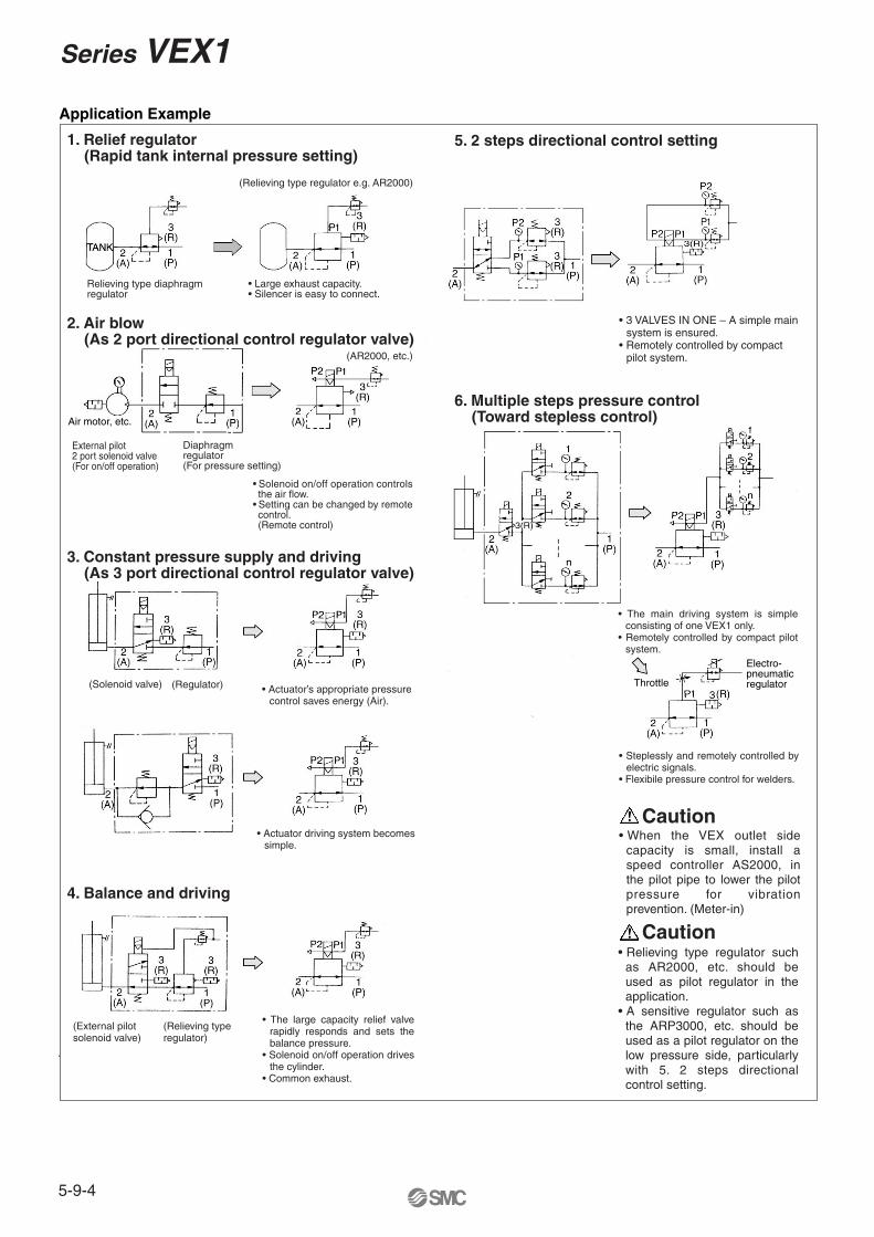
1. Relief regulator (Rapid tank internal pressure setting)
5. 2 steps directional control setting
2. Air blow (As 2 port directional control regulator valve)
3. Constant pressure supply and driving (As 3 port directional control regulator valve)
4. Balance and driving
• Large exhaust capacity.• Silencer is easy to connect.
Relieving type diaphragm regulator
(Relieving type regulator e.g. AR2000)
External pilot2 port solenoid valve(For on/off operation)
• Solenoid on/off operation controls the air flow.
• Setting can be changed by remote control.(Remote control)
Diaphragmregulator(For pressure setting)
(AR2000, etc.)
• Actuator’s appropriate pressure control saves energy (Air).
• Actuator driving system becomes simple.
• The large capacity relief valve rapidly responds and sets the balance pressure.
• Solenoid on/off operation drives the cylinder.
• Common exhaust.
(Solenoid valve) (Regulator)
(External pilot solenoid valve)
(Relieving type regulator)
• 3 VALVES IN ONE – A simple main system is ensured.
• Remotely controlled by compact pilot system.
6. Multiple steps pressure control (Toward stepless control)
• The main driving system is simple consisting of one VEX1 only.
• Remotely controlled by compact pilot system.
• Steplessly and remotely controlled by electric signals.
• Flexibile pressure control for welders.
Caution• When the VEX outlet side
capacity is small, install a speed controller AS2000, in the pilot pipe to lower the pilot pressure for vibration prevention. (Meter-in)
• Relieving type regulator such as AR2000, etc. should be used as pilot regulator in the application.
• A sensitive regulator such as the ARP3000, etc. should be used as a pilot regulator on the low pressure side, particularly with 5. 2 steps directional control setting.
Application Example
Air motor, etc.
Throttle
Electro-pneumaticregulator
Caution
Series VEX1
5-9-4
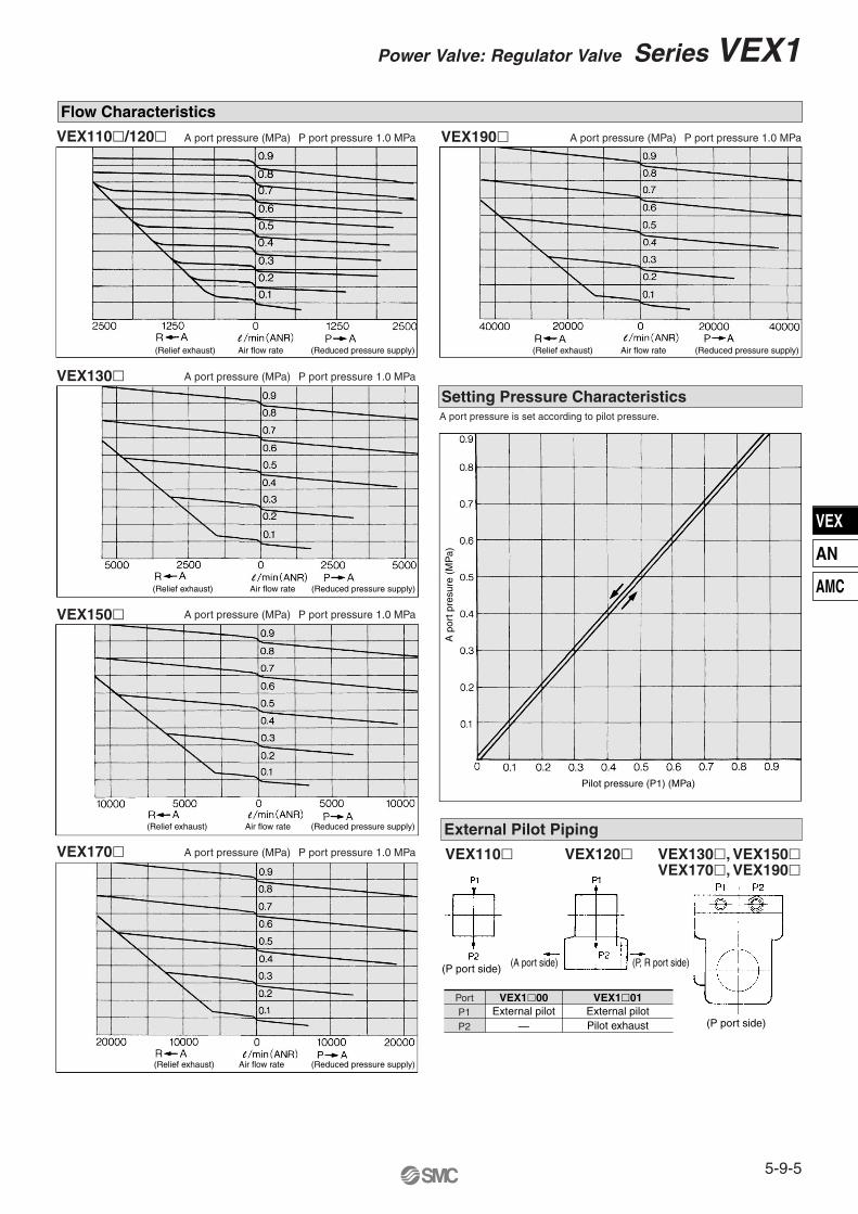
Flow Characteristics
VEX130�
VEX150�
VEX170�
VEX190�
Setting Pressure CharacteristicsA port pressure is set according to pilot pressure.
External Pilot Piping
Port VEX1�00 VEX1�01P1 External pilot External pilotP2 — Pilot exhaust
VEX110�/120�
VEX110� VEX120� VEX130�, VEX150�VEX170�, VEX190�
(Relief exhaust) Air flow rate (Reduced pressure supply)
(Relief exhaust) Air flow rate (Reduced pressure supply)
(Relief exhaust) Air flow rate (Reduced pressure supply)
(Relief exhaust) Air flow rate (Reduced pressure supply)
(Relief exhaust) Air flow rate (Reduced pressure supply)
(P port side) (A port side) (P, R port side)
(P port side)
Pilot pressure (P1) (MPa)
A p
ort p
resu
re (
MP
a)
P port pressure 1.0 MPaA port pressure (MPa) P port pressure 1.0 MPaA port pressure (MPa)
P port pressure 1.0 MPaA port pressure (MPa)
P port pressure 1.0 MPaA port pressure (MPa)
P port pressure 1.0 MPaA port pressure (MPa)
5-9-5
Power Valve: Regulator Valve Series VEX1
VEX
AN
AMC
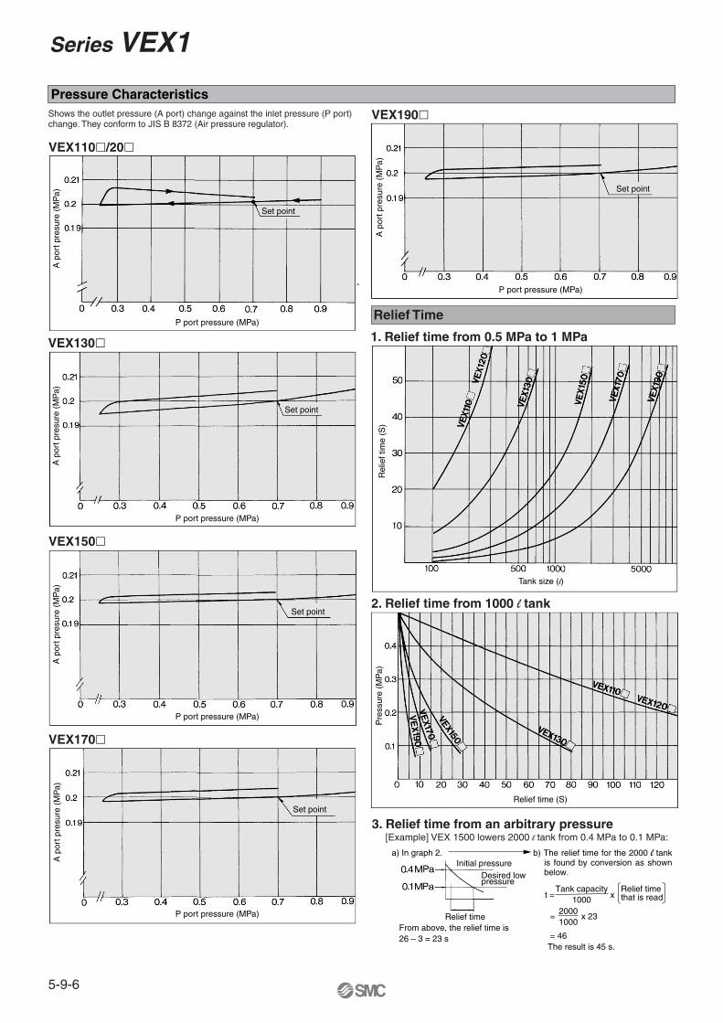
Pressure Characteristics
VEX110�/20�
VEX130�
VEX150�
VEX170�
VEX190�
Relief Time
1. Relief time from 0.5 MPa to 1 MPa
Shows the outlet pressure (A port) change against the inlet pressure (P port) change. They conform to JIS B 8372 (Air pressure regulator).
2. Relief time from 1000 l tank
3. Relief time from an arbitrary pressure [Example] VEX 1500 lowers 2000 l tank from 0.4 MPa to 0.1 MPa:
a) In graph 2.
t =
=
= 46The result is 45 s.
From above, the relief time is26 – 3 = 23 s
x 23
x Tank capacity
1000Relief time that is read
20001000
b) The relief time for the 2000 l tank is found by conversion as shown below.
A p
ort p
resu
re (
MP
a)
P port pressure (MPa)
Set point
A p
ort p
resu
re (
MP
a)
P port pressure (MPa)
Set point
A p
ort p
resu
re (
MP
a)
P port pressure (MPa)
Set point
A p
ort p
resu
re (
MP
a)
P port pressure (MPa)
Set point
A p
ort p
resu
re (
MP
a)
P port pressure (MPa)
Set point
Rel
ief t
ime
(S)
Tank size (l)
Pre
ssur
e (M
Pa)
Relief time (S)
Initial pressureDesired lowpressure
Relief time
Series VEX1
5-9-6
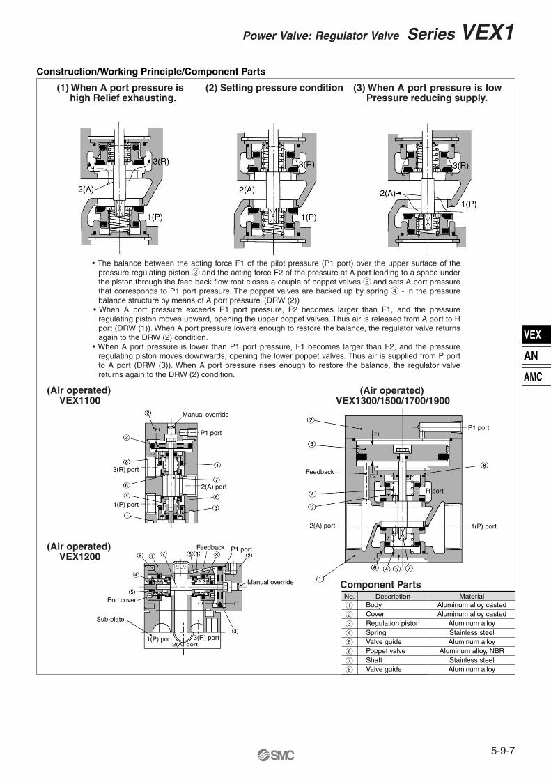
Construction/Working Principle/Component Parts
(Air operated) VEX1100
• The balance between the acting force F1 of the pilot pressure (P1 port) over the upper surface of the pressure regulating piston e and the acting force F2 of the pressure at A port leading to a space under the piston through the feed back flow root closes a couple of poppet valves y and sets A port pressure that corresponds to P1 port pressure. The poppet valves are backed up by spring r - in the pressure balance structure by means of A port pressure. (DRW (2))
• When A port pressure exceeds P1 port pressure, F2 becomes larger than F1, and the pressure regulating piston moves upward, opening the upper poppet valves. Thus air is released from A port to R port (DRW (1)). When A port pressure lowers enough to restore the balance, the regulator valve returns again to the DRW (2) condition.
• When A port pressure is lower than P1 port pressure, F1 becomes larger than F2, and the pressure regulating piston moves downwards, opening the lower poppet valves. Thus air is supplied from P port to A port (DRW (3)). When A port pressure rises enough to restore the balance, the regulator valve returns again to the DRW (2) condition.
(1) When A port pressure is high Relief exhausting.
(3) When A port pressure is low Pressure reducing supply.
(Air operated) VEX1300/1500/1700/1900
Component PartsNo.
w
e
q
Description
Aluminum alloy castedAluminum alloy casted
Material
Aluminum alloyr Stainless steelt Aluminum alloyy Aluminum alloy, NBRu Stainless steeli Aluminum alloy
CoverBody
Regulation pistonSpringValve guidePoppet valveShaftValve guide
(Air operated) VEX1200
Manual override
3(R) port
1(P) port
P1 port
2(A) port
End cover
Sub-plate
1(P) port 3(R) port
Feedback
2(A) port
P1 port
Manual override
Feedback
2(A) port
P1 port
R port
1(P) port
(2) Setting pressure condition
5-9-7
Power Valve: Regulator Valve Series VEX1
VEX
AN
AMC
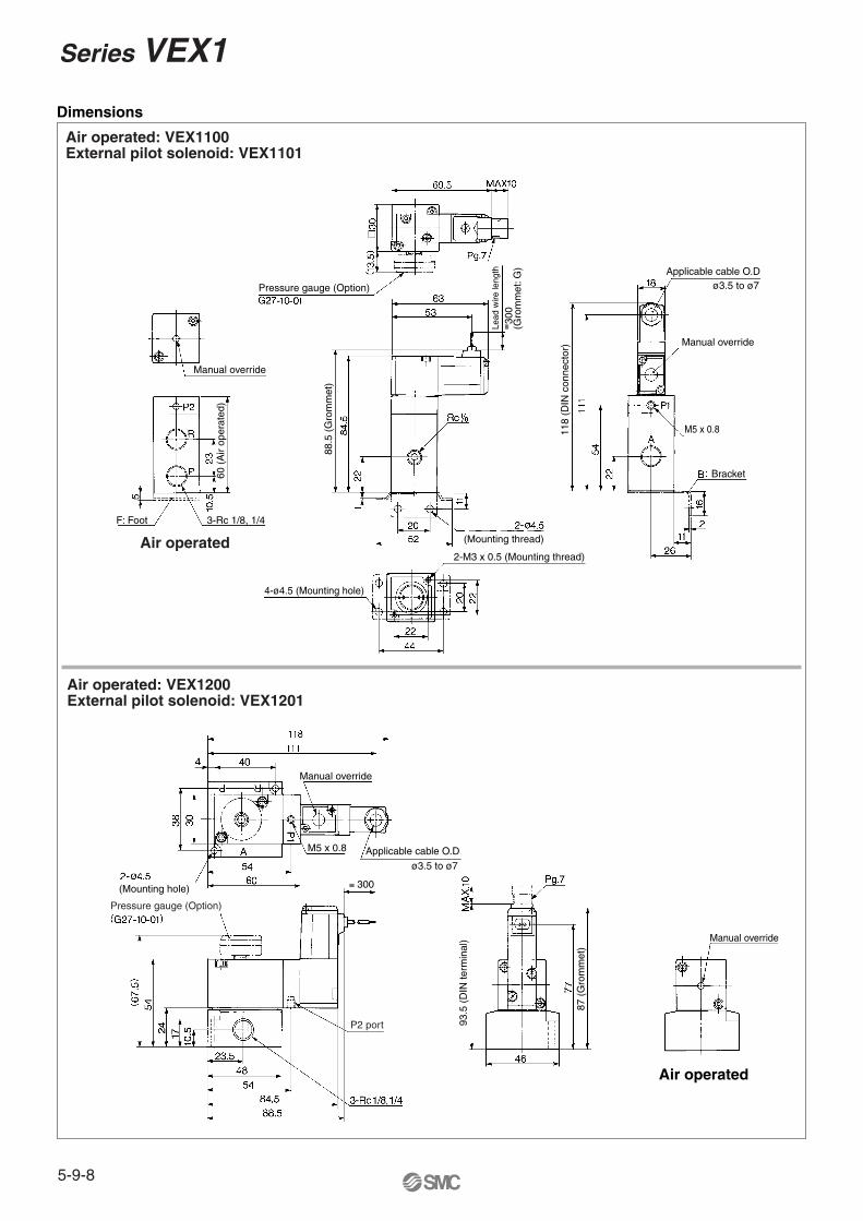
Dimensions
Air operated: VEX1100External pilot solenoid: VEX1101
Air operated: VEX1200External pilot solenoid: VEX1201
Air operated
Manual override
F: Foot
60 (
Air
oper
ated
)
3-Rc 1/8, 1/4
Pressure gauge (Option)
88.5
(G
rom
met
)
Lead
wire
leng
th≅ 3
00(G
rom
met
: G)
4-ø4.5 (Mounting hole)
2-M3 x 0.5 (Mounting thread)
(Mounting thread)
118
(DIN
con
nect
or)
Applicable cable O.Dø3.5 to ø7
Manual override
M5 x 0.8
Bracket
(Mounting hole)
Manual override
M5 x 0.8 Applicable cable O.D
ø3.5 to ø7
≅ 300
Pressure gauge (Option)
P2 port 93.5
(D
IN te
rmin
al)
87 (
Gro
mm
et)
Manual override
Air operated
Series VEX1
5-9-8
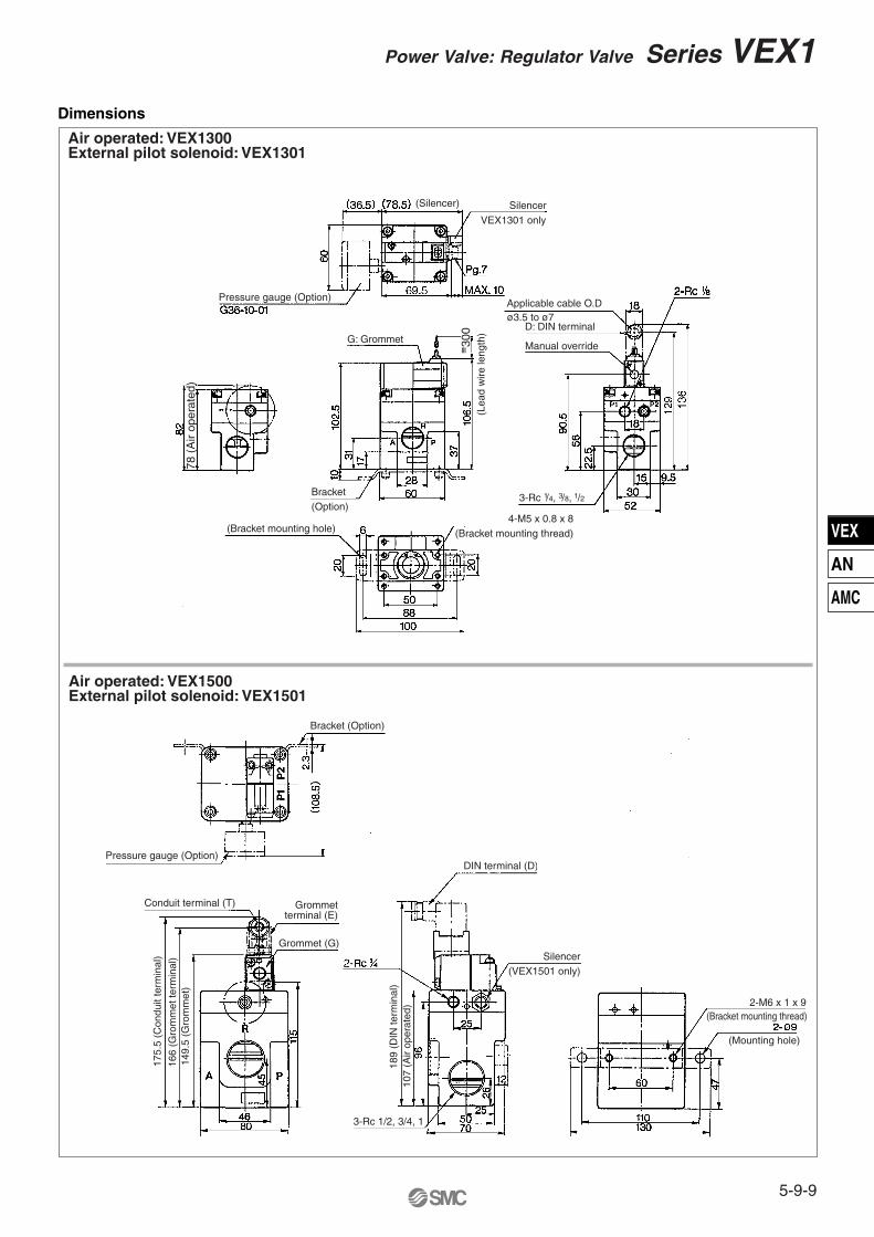
Dimensions
Air operated: VEX1300External pilot solenoid: VEX1301
Air operated: VEX1500External pilot solenoid: VEX1501
Pressure gauge (Option)
(Silencer) SilencerVEX1301 only
78 (
Air
oper
ated
)
G: Grommet
≅ 300
Bracket(Option)
(Lea
d w
ire le
ngth
)
(Bracket mounting hole)4-M5 x 0.8 x 8
(Bracket mounting thread)
Applicable cable O.D
D: DIN terminal
Manual override
3-Rc 1/4, 3/8, 1/2
ø3.5 to ø7
Pressure gauge (Option)
Bracket (Option)
Conduit terminal (T)
175.
5 (C
ondu
it te
rmin
al)
166
(Gro
mm
et te
rmin
al)
149.
5 (G
rom
met
)
Grommetterminal (E)
Grommet (G)
189
(DIN
term
inal
)10
7 (A
ir op
erat
ed)
3-Rc 1/2, 3/4, 1
DIN terminal (D)
Silencer(VEX1501 only)
2-M6 x 1 x 9(Bracket mounting thread)
(Mounting hole)
5-9-9
Power Valve: Regulator Valve Series VEX1
VEX
AN
AMC
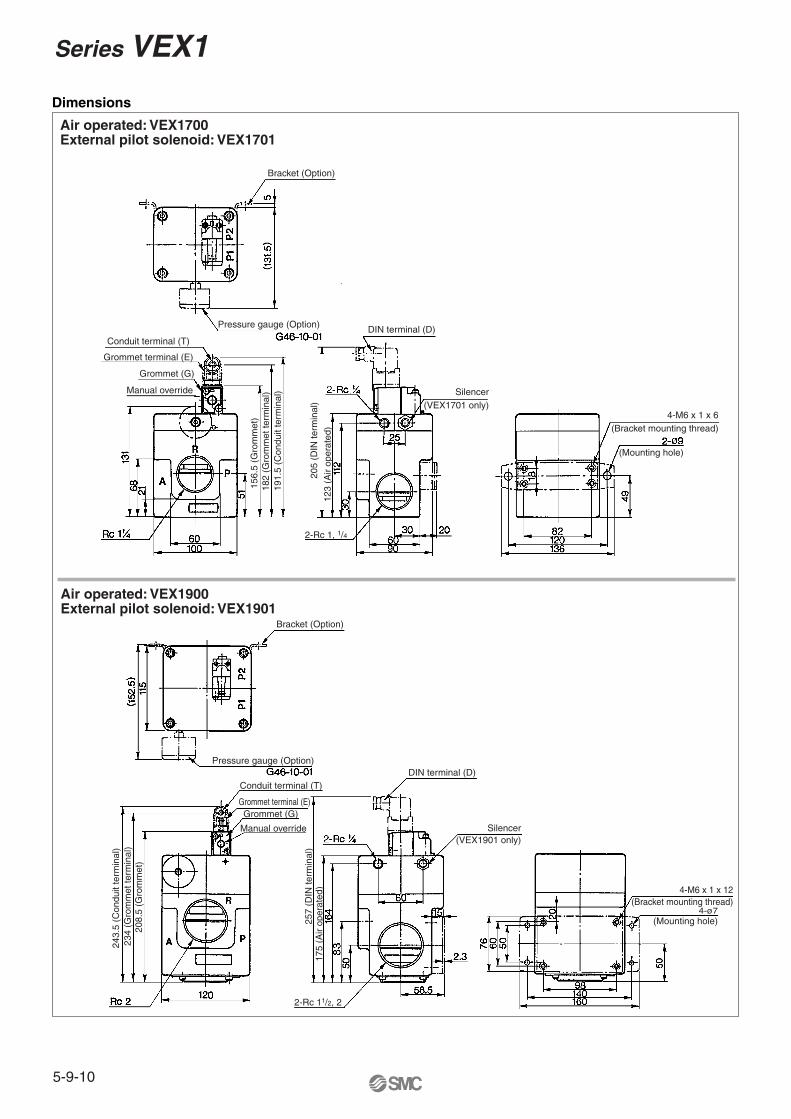
Dimensions
Air operated: VEX1900External pilot solenoid: VEX1901
Air operated: VEX1700External pilot solenoid: VEX1701
Bracket (Option)
Pressure gauge (Option)
Conduit terminal (T)
Grommet terminal (E)
Grommet (G)
Manual override
156.
5 (G
rom
met
)
205
(DIN
term
inal
)
182
(Gro
mm
et te
rmin
al)
191.
5 (C
ondu
it te
rmin
al)
123
(Air
oper
ated
)
2-Rc 1, 1/4
DIN terminal (D)
Silencer(VEX1701 only)
4-M6 x 1 x 6(Bracket mounting thread)
(Mounting hole)
Bracket (Option)
Pressure gauge (Option)
243.
5 (C
ondu
it te
rmin
al)
234
(Gro
mm
et te
rmin
al)
208.
5 (G
rom
met
)
Conduit terminal (T)
Grommet terminal (E)Grommet (G)
Manual override
257
(DIN
term
inal
)17
5 (A
ir op
erat
ed)
DIN terminal (D)
Silencer(VEX1901 only)
2-Rc 11/2, 2
4-M6 x 1 x 12(Bracket mounting thread)
4-ø7(Mounting hole)
Series VEX1
5-9-10