Embed Size (px)
Citation preview
TYPICAL SYSTEM ARRANGEMENTS
SCREW JACKPOWER TRANSMISSION COMPONENTS
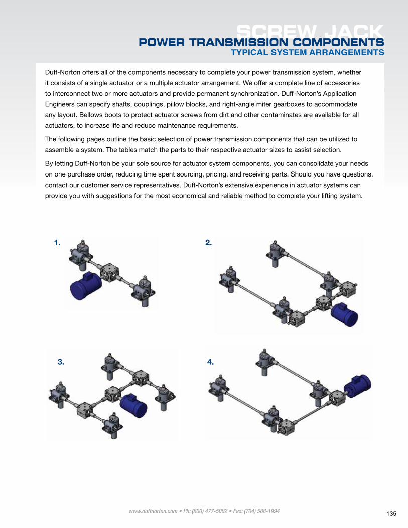
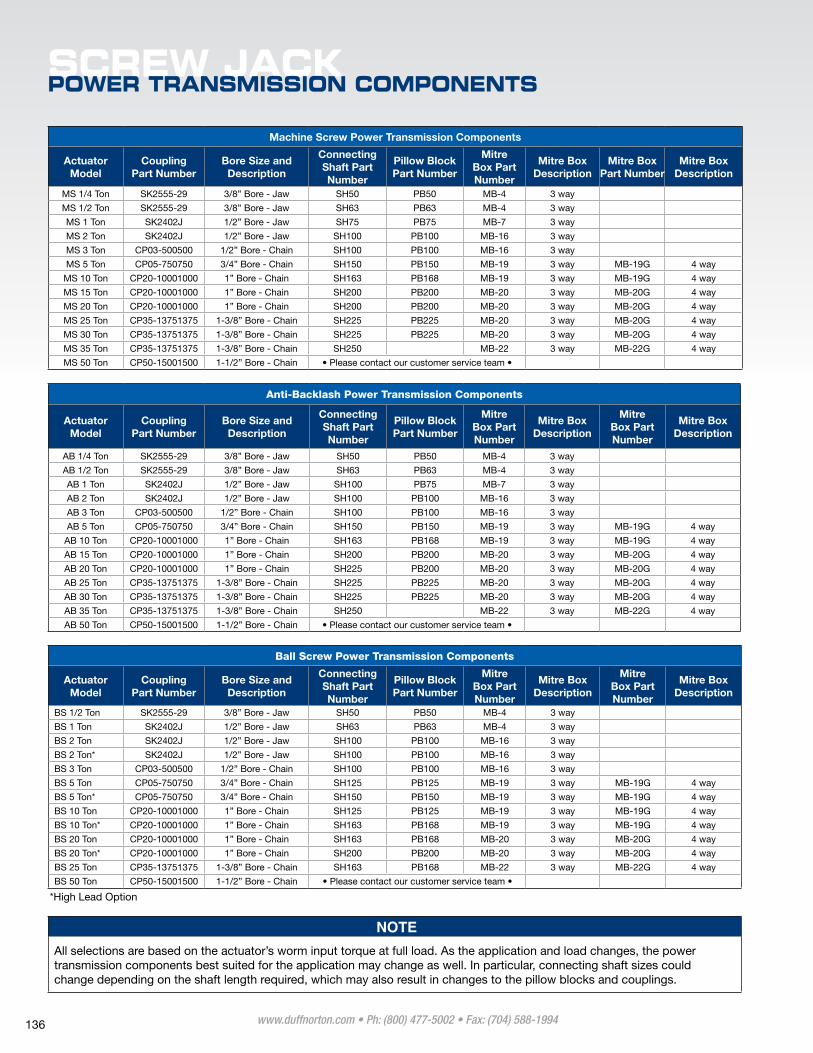
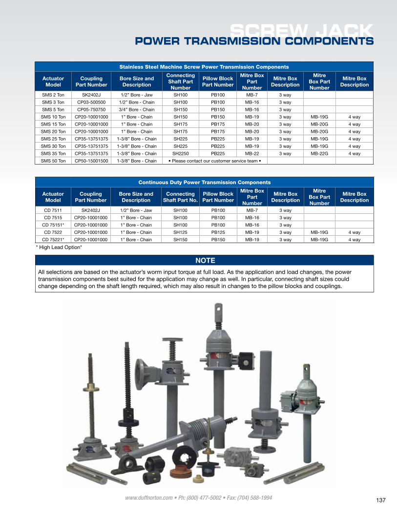
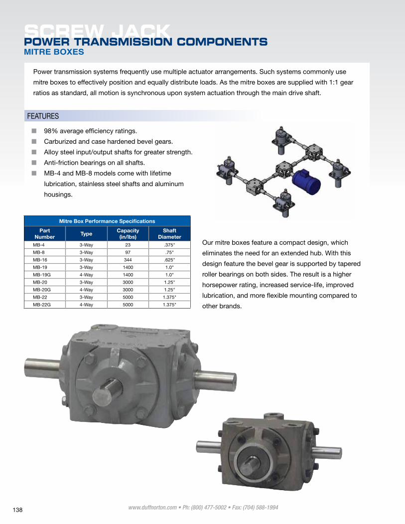
Duff-Norton offers all of the components necessary to complete your power transmission system, whether
it consists of a single actuator or a multiple actuator arrangement. We offer a complete line of accessories
to interconnect two or more actuators and provide permanent synchronization. Duff-Norton’s Application
engineers can specify shafts, couplings, pillow blocks, and right-angle miter gearboxes to accommodate
any layout. Bellows boots to protect actuator screws from dirt and other contaminates are available for all
actuators, to increase life and reduce maintenance requirements.
The following pages outline the basic selection of power transmission components that can be utilized to
assemble a system. The tables match the parts to their respective actuator sizes to assist selection.
By letting Duff-Norton be your sole source for actuator system components, you can consolidate your needs
on one purchase order, reducing time spent sourcing, pricing, and receiving parts. Should you have questions,
contact our customer service representatives. Duff-Norton’s extensive experience in actuator systems can
provide you with suggestions for the most economical and reliable method to complete your lifting system.
1.
3.
2.
4.
www.duffnorton.com • Ph: (800) 477-5002 • Fax: (704) 588-1994 135
SCREW JACKPOWER TRANSMISSION COMPONENTS
Machine Screw Power Transmission Components
Actuator Model
Coupling Part Number
Bore Size and Description
Connecting Shaft Part Number
Pillow Block Part Number
Mitre Box Part Number
Mitre Box Description
Mitre Box Part Number
Mitre Box Description
mS 1/4 Ton Sk2555-29 3/8” Bore - Jaw Sh50 pB50 mB-4 3 way
mS 1/2 Ton Sk2555-29 3/8” Bore - Jaw Sh63 pB63 mB-4 3 way
mS 1 Ton Sk2402J 1/2” Bore - Jaw Sh75 pB75 mB-7 3 way
mS 2 Ton Sk2402J 1/2” Bore - Jaw Sh100 pB100 mB-16 3 way
mS 3 Ton Cp03-500500 1/2” Bore - Chain Sh100 pB100 mB-16 3 way
mS 5 Ton Cp05-750750 3/4” Bore - Chain Sh150 pB150 mB-19 3 way mB-19G 4 way
mS 10 Ton Cp20-10001000 1” Bore - Chain Sh163 pB168 mB-19 3 way mB-19G 4 way
mS 15 Ton Cp20-10001000 1” Bore - Chain Sh200 pB200 mB-20 3 way mB-20G 4 way
mS 20 Ton Cp20-10001000 1” Bore - Chain Sh200 pB200 mB-20 3 way mB-20G 4 way
mS 25 Ton Cp35-13751375 1-3/8” Bore - Chain Sh225 pB225 mB-20 3 way mB-20G 4 way
mS 30 Ton Cp35-13751375 1-3/8” Bore - Chain Sh225 pB225 mB-20 3 way mB-20G 4 way
mS 35 Ton Cp35-13751375 1-3/8” Bore - Chain Sh250 mB-22 3 way mB-22G 4 way
mS 50 Ton Cp50-15001500 1-1/2” Bore - Chain • Please contact our customer service team •
Anti-Backlash Power Transmission Components
Actuator Model
Coupling Part Number
Bore Size and Description
Connecting Shaft Part Number
Pillow Block Part Number
Mitre Box Part Number
Mitre Box Description
Mitre Box Part Number
Mitre Box Description
AB 1/4 Ton Sk2555-29 3/8” Bore - Jaw Sh50 pB50 mB-4 3 way
AB 1/2 Ton Sk2555-29 3/8” Bore - Jaw Sh63 pB63 mB-4 3 way
AB 1 Ton Sk2402J 1/2” Bore - Jaw Sh100 pB75 mB-7 3 way
AB 2 Ton Sk2402J 1/2” Bore - Jaw Sh100 pB100 mB-16 3 way
AB 3 Ton Cp03-500500 1/2” Bore - Chain Sh100 pB100 mB-16 3 way
AB 5 Ton Cp05-750750 3/4” Bore - Chain Sh150 pB150 mB-19 3 way mB-19G 4 way
AB 10 Ton Cp20-10001000 1” Bore - Chain Sh163 pB168 mB-19 3 way mB-19G 4 way
AB 15 Ton Cp20-10001000 1” Bore - Chain Sh200 pB200 mB-20 3 way mB-20G 4 way
AB 20 Ton Cp20-10001000 1” Bore - Chain Sh225 pB200 mB-20 3 way mB-20G 4 way
AB 25 Ton Cp35-13751375 1-3/8” Bore - Chain Sh225 pB225 mB-20 3 way mB-20G 4 way
AB 30 Ton Cp35-13751375 1-3/8” Bore - Chain Sh225 pB225 mB-20 3 way mB-20G 4 way
AB 35 Ton Cp35-13751375 1-3/8” Bore - Chain Sh250 mB-22 3 way mB-22G 4 way
AB 50 Ton Cp50-15001500 1-1/2” Bore - Chain • Please contact our customer service team •
Ball Screw Power Transmission Components
Actuator Model
Coupling Part Number
Bore Size and Description
Connecting Shaft Part Number
Pillow Block Part Number
Mitre Box Part Number
Mitre Box Description
Mitre Box Part Number
Mitre Box Description
BS 1/2 Ton Sk2555-29 3/8” Bore - Jaw Sh50 pB50 mB-4 3 way
BS 1 Ton Sk2402J 1/2” Bore - Jaw Sh63 pB63 mB-4 3 way
BS 2 Ton Sk2402J 1/2” Bore - Jaw Sh100 pB100 mB-16 3 way
BS 2 Ton* Sk2402J 1/2” Bore - Jaw Sh100 pB100 mB-16 3 way
BS 3 Ton Cp03-500500 1/2” Bore - Chain Sh100 pB100 mB-16 3 way
BS 5 Ton Cp05-750750 3/4” Bore - Chain Sh125 pB125 mB-19 3 way mB-19G 4 way
BS 5 Ton* Cp05-750750 3/4” Bore - Chain Sh150 pB150 mB-19 3 way mB-19G 4 way
BS 10 Ton Cp20-10001000 1” Bore - Chain Sh125 pB125 mB-19 3 way mB-19G 4 way
BS 10 Ton* Cp20-10001000 1” Bore - Chain Sh163 pB168 mB-19 3 way mB-19G 4 way
BS 20 Ton Cp20-10001000 1” Bore - Chain Sh163 pB168 mB-20 3 way mB-20G 4 way
BS 20 Ton* Cp20-10001000 1” Bore - Chain Sh200 pB200 mB-20 3 way mB-20G 4 way
BS 25 Ton Cp35-13751375 1-3/8” Bore - Chain Sh163 pB168 mB-22 3 way mB-22G 4 way
BS 50 Ton Cp50-15001500 1-1/2” Bore - Chain • Please contact our customer service team •
*high lead Option
NOTE
All selections are based on the actuator’s worm input torque at full load. As the application and load changes, the power transmission components best suited for the application may change as well. In particular, connecting shaft sizes could change depending on the shaft length required, which may also result in changes to the pillow blocks and couplings.
www.duffnorton.com • Ph: (800) 477-5002 • Fax: (704) 588-1994 136
SCREW JACKPOWER TRANSMISSION COMPONENTS
Continuous Duty Power Transmission Components
Actuator Model
Coupling Part Number
Bore Size and Description
Connecting Shaft Part No.
Pillow Block Part Number
Mitre Box Part
Number
Mitre Box Description
Mitre Box Part Number
Mitre Box Description
CD 7511 Sk2402J 1/2” Bore - Jaw Sh100 pB100 mB-7 3 way
CD 7515 Cp20-10001000 1” Bore - Chain Sh100 pB100 mB-16 3 way
CD 75151* Cp20-10001000 1” Bore - Chain Sh100 pB100 mB-16 3 way
CD 7522 Cp20-10001000 1” Bore - Chain Sh125 pB125 mB-19 3 way mB-19G 4 way
CD 75221* Cp20-10001000 1” Bore - Chain Sh150 pB150 mB-19 3 way mB-19G 4 way
* high lead Option*
Stainless Steel Machine Screw Power Transmission Components
Actuator Model
Coupling Part Number
Bore Size and Description
Connecting Shaft Part Number
Pillow Block Part Number
Mitre Box Part
Number
Mitre Box Description
Mitre Box Part Number
Mitre Box Description
SmS 2 Ton Sk2402J 1/2” Bore - Jaw Sh100 pB100 mB-7 3 way
SmS 3 Ton Cp03-500500 1/2” Bore - Chain Sh100 pB100 mB-16 3 way
SmS 5 Ton Cp05-750750 3/4” Bore - Chain Sh150 pB150 mB-16 3 way
SmS 10 Ton Cp20-10001000 1” Bore - Chain Sh150 pB150 mB-19 3 way mB-19G 4 way
SmS 15 Ton Cp20-10001000 1” Bore - Chain Sh175 pB175 mB-20 3 way mB-20G 4 way
SmS 20 Ton Cp20-10001000 1” Bore - Chain Sh175 pB175 mB-20 3 way mB-20G 4 way
SmS 25 Ton Cp35-13751375 1-3/8” Bore - Chain Sh225 pB225 mB-19 3 way mB-19G 4 way
SmS 30 Ton Cp35-13751375 1-3/8” Bore - Chain Sh225 pB225 mB-19 3 way mB-19G 4 way
SmS 35 Ton Cp35-13751375 1-3/8” Bore - Chain Sh2250 pB225 mB-22 3 way mB-22G 4 way
SmS 50 Ton Cp50-15001500 1-3/8” Bore - Chain • Please contact our customer service team •
NOTE
All selections are based on the actuator’s worm input torque at full load. As the application and load changes, the power transmission components best suited for the application may change as well. In particular, connecting shaft sizes could change depending on the shaft length required, which may also result in changes to the pillow blocks and couplings.
www.duffnorton.com • Ph: (800) 477-5002 • Fax: (704) 588-1994 137
SCREW JACKPOWER TRANSMISSION COMPONENTSMITRE BOXES
power transmission systems frequently use multiple actuator arrangements. Such systems commonly use
mitre boxes to effectively position and equally distribute loads. As the mitre boxes are supplied with 1:1 gear
ratios as standard, all motion is synchronous upon system actuation through the main drive shaft.
Our mitre boxes feature a compact design, which
eliminates the need for an extended hub. With this
design feature the bevel gear is supported by tapered
roller bearings on both sides. The result is a higher
horsepower rating, increased service-life, improved
lubrication, and more flexible mounting compared to
other brands.
Mitre Box Performance Specifications
PartNumber
TypeCapacity(in/lbs)
Shaft Diameter
mB-4 3-Way 23 .375"
mB-8 3-Way 97 .75"
mB-16 3-Way 344 .625"
mB-19 3-Way 1400 1.0"
mB-19G 4-Way 1400 1.0"
mB-20 3-Way 3000 1.25"
mB-20G 4-Way 3000 1.25"
mB-22 3-Way 5000 1.375"
mB-22G 4-Way 5000 1.375"
■■ 98% average efficiency ratings.
■■ Carburized and case hardened bevel gears.
■■ Alloy steel input/output shafts for greater strength.
■■ Anti-friction bearings on all shafts.
■■ mB-4 and mB-8 models come with lifetime
lubrication, stainless steel shafts and aluminum
housings.
FeATUReS
www.duffnorton.com • Ph: (800) 477-5002 • Fax: (704) 588-1994 138
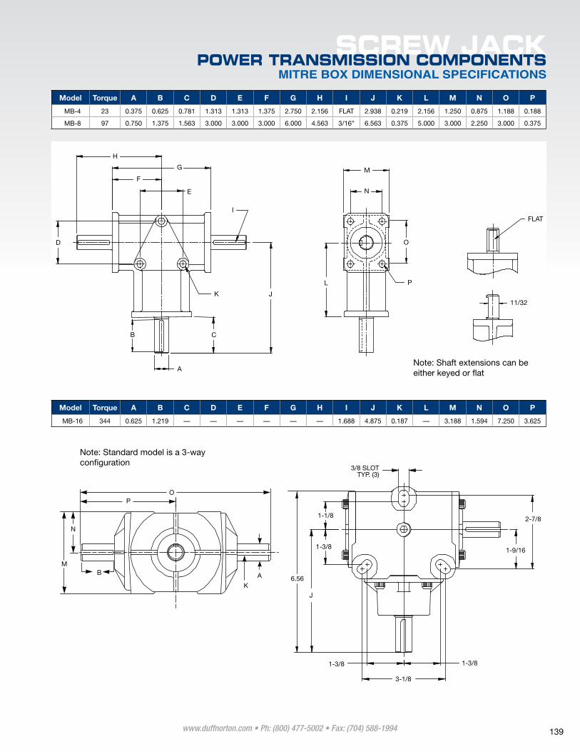
MITRE BOX DIMENSIONAL SPECIFICATIONS
SCREW JACKPOWER TRANSMISSION COMPONENTS
H
G
F
E
I
D
B C
J
L
M
N
O
P
FLAT
11/32
A
K
M
N
B
K
A
3/8 SLOTTYP. (3)
1-1/8
1-3/8
1-3/8 1-3/8
3-1/8
2-7/8
1-9/16
PO
6.56
J
Note: Shaft extensions can be either keyed or flat
Note: Standard model is a 3-way configuration
Model Torque A B C D E F G H I J K L M N O P
mB-4 23 0.375 0.625 0.781 1.313 1.313 1.375 2.750 2.156 FlAT 2.938 0.219 2.156 1.250 0.875 1.188 0.188
mB-8 97 0.750 1.375 1.563 3.000 3.000 3.000 6.000 4.563 3/16” 6.563 0.375 5.000 3.000 2.250 3.000 0.375
Model Torque A B C D E F G H I J K L M N O P
mB-16 344 0.625 1.219 — — — — — — 1.688 4.875 0.187 — 3.188 1.594 7.250 3.625
www.duffnorton.com • Ph: (800) 477-5002 • Fax: (704) 588-1994 139
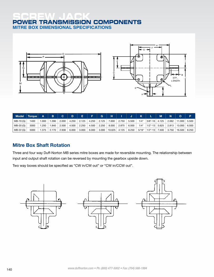
SCREW JACKPOWER TRANSMISSION COMPONENTSMITRE BOX DIMENSIONAL SPECIFICATIONS
Mitre Box Shaft Rotation Three and four way Duff-Norton mB series mitre boxes are made for reversible mounting. The relationship between
input and output shaft rotation can be reversed by mounting the gearbox upside down.
Two way boxes should be specified as “CW in/CW out” or “CW in/CCW out”.
K
A
L
GF
H
E
D
I
J
B
C
EFF . L ENGTH
M
N
OP
Model Torque A B C D E F G H I J K L M N O P
mB-19 (G) 1400 1.000 1.396 2.000 4.250 2.125 4.250 2.125 7.000 2.750 5.500 1/4" 3/8"-16 4.125 2.062 11.000 5.500
mB-20 (G) 3000 1.250 1.840 2.500 4.500 2.250 4.500 2.250 8.000 2.875 6.500 1/4" 1/2"-13 5.625 2.813 13.000 6.500
mB-22 (G) 5000 1.375 2.170 2.938 6.000 3.000 6.000 3.000 10.625 4.125 8.250 5/16" 1/2"-13 7.500 3.750 16.500 8.250
www.duffnorton.com • Ph: (800) 477-5002 • Fax: (704) 588-1994 140
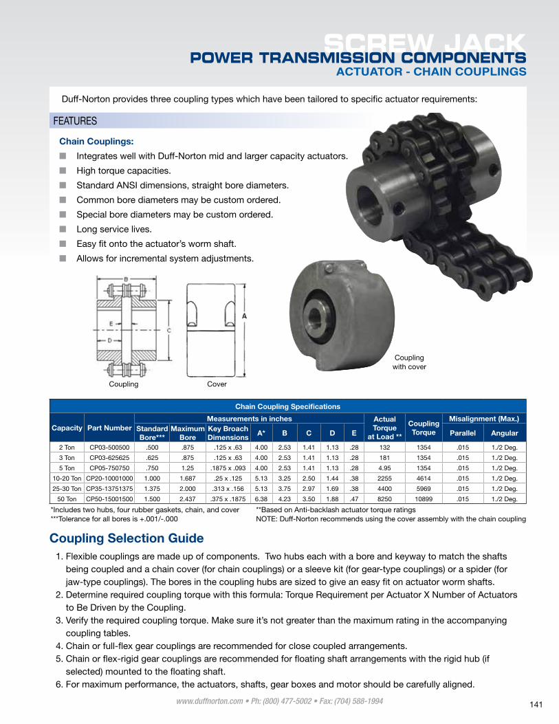
ACTUATOR - CHAIN COUPLINGS
SCREW JACKPOWER TRANSMISSION COMPONENTS
Duff-Norton provides three coupling types which have been tailored to specific actuator requirements:
Coupling Selection Guide1. Flexible couplings are made up of components. T wo hubs each with a bore and keyway to match the shafts
being coupled and a chain cover (for chain couplings) or a sleeve kit (for gear-type couplings) or a spider (for jaw-type couplings). The bores in the coupling hubs are sized to give an easy fit on actuator worm shafts.
2. Determine required coupling torque with this formula: Torque Requirement per Actuator X Number of Actuators to Be Driven by the Coupling.
3. verify the required coupling torque. make sure it’s not greater than the maximum rating in the accompanying coupling tables.
4. Chain or full-flex gear couplings are recommended for close coupled arrangements. 5. Chain or flex-rigid gear couplings are recommended for floating shaft arrangements with the rigid hub (if
selected) mounted to the floating shaft. 6. For maximum performance, the actuators, shafts, gear boxes and motor should be carefully aligned.
Coupling with cover
Coupling Cover
Chain Coupling Specifications
Capacity Part NumberMeasurements in inches Actual
Torque at Load **
Coupling Torque
Misalignment (Max.)Standard Bore***
Maximum Bore
Key Broach Dimensions
A* B C D E Parallel Angular
2 Ton Cp03-500500 .500 .875 .125 x .63 4.00 2.53 1.41 1.13 .28 132 1354 .015 1./2 Deg.
3 Ton Cp03-625625 .625 .875 .125 x .63 4.00 2.53 1.41 1.13 .28 181 1354 .015 1./2 Deg.
5 Ton Cp05-750750 .750 1.25 .1875 x .093 4.00 2.53 1.41 1.13 .28 4.95 1354 .015 1./2 Deg.
10-20 Ton Cp20-10001000 1.000 1.687 .25 x .125 5.13 3.25 2.50 1.44 .38 2255 4614 .015 1./2 Deg.
25-30 Ton Cp35-13751375 1.375 2.000 .313 x .156 5.13 3.75 2.97 1.69 .38 4400 5969 .015 1./2 Deg.
50 Ton Cp50-15001500 1.500 2.437 .375 x .1875 6.38 4.23 3.50 1.88 .47 8250 10899 .015 1./2 Deg.
*Includes two hubs, four rubber gaskets, chain, and cover **Based on Anti-backlash actuator torque ratings ***Tolerance for all bores is +.001/-.000 NOTe: Duff-Norton recommends using the cover assembly with the chain coupling
Chain Couplings:
■■ Integrates well with Duff-Norton mid and larger capacity actuators.
■■ high torque capacities.
■■ Standard ANSI dimensions, straight bore diameters.
■■ Common bore diameters may be custom ordered.
■■ Special bore diameters may be custom ordered.
■■ long service lives.
■■ easy fit onto the actuator’s worm shaft.
■■ Allows for incremental system adjustments.
FeATUReS
www.duffnorton.com • Ph: (800) 477-5002 • Fax: (704) 588-1994 141
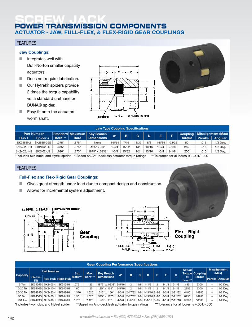
SCREW JACKPOWER TRANSMISSION COMPONENTSACTUATOR - JAW, FULL-FLEX, & FLEX-RIGID GEAR COUPLINGS
Jaw Type Coupling Specifications
Part Number Standard Bore***
Maximum Bore
Key Broach Dimensions
A* B C D E FCoupling Torque
Misalignment (Max)Hub # Spider # Parallel Angular
Sk2555h2 Sk2555-29S .375" .875" None 1-5/64 7/16 15/32 5/8 1-5/64 1-23/32 50 .015 1/2 Deg.
Sk2402J-h1 Sk2402-JS .375" .875" .125" x .63" 1-3/4 15/32 1/2 13/16 1-3/4 2-1/8 250 .015 1/2 Deg.
Sk2402J-h2 Sk2402-JS .626" .875" .1875" x .0938" 1-3/4 15/32 1/2 13/16 1-3/4 2-1/8 250 .015 1/2 Deg.
*Includes two hubs, and hytrel spider **Based on Anti-backlash actuator torque ratings ***Tolerance for all bores is +.001/-.000
Gear Coupling Performance Specifications
CapacityPart Number
Std. Bore***
Max. Bore***
Key Broach Dimensions
A* B C D E F H
Actual Torque
at Load**
Coupling Torque
Misalignment (Max)
Sleeve Kit
Flex Hub Rigid Hub Parallel Angular
5 Ton Sk2405S Sk2405h Sk2404h .0751 1.25 .1875" x .0938" 3-5/16 2 1/8 1-1/2 2 3-1/8 2-1/8 495 6300 + 1/2 Deg.
10-20 Ton Sk2410S Sk2410h Sk2409h 1.001 1.25 .25" x .125" 3-5/16 2 1/8 1-1/2 2 3-1/8 2-1/8 2255 6300 + 1/2 Deg.
25-35 Ton Sk2425S Sk2425h Sk2424h 1.376 1.625 .313" x .156" 3-3/4 2-17/32 1/8 1-13/16 2-3/8 3-3/4 2-21/32 4400 18900 + 1/2 Deg.
50 Ton Sk2450S Sk2450h Sk2449h 1.501 1.625 .375" x .1875" 3-3/4 2-17/32 1/8 1-13/16 2-3/8 3-3/4 2-21/32 8250 18900 + 1/2 Deg.
100 Ton Sk2499S Sk2499h Sk2498h 1.751 2.125 .50" x .25" 4-3/4 2-9/16 1/8 2-1/16 3-1/4 4-1/4 2-11/16 17600 50000 + 1/2 Deg.
*Includes two hubs, and hytrel spider **Based on Anti-backlash actuator torque ratings ***Tolerance for all bores is +.001/-.000
FeATUReS
FeATUReS
Jaw Couplings:
■■ Integrates well with
Duff-Norton smaller capacity
actuators.
■■ Does not require lubrication.
■■ Our hytrel® spiders provide
2 times the torque capability
vs. a standard urethane or
BUNA® spider.
■■ easy fit onto the actuators
worm shaft.
Full-Flex and Flex-Rigid Gear Couplings:
■■ Gives great strength under load due to compact design and construction.
■■ Allows for incremental system adjustment.
www.duffnorton.com • Ph: (800) 477-5002 • Fax: (704) 588-1994 142
CONNECTING SHAFTS
SCREW JACKPOWER TRANSMISSION COMPONENTS
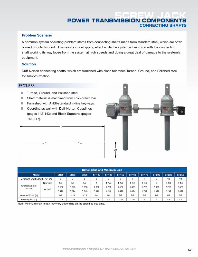
Problem Scenario
A common system operating problem stems from connecting shafts made from standard steel, which are often
bowed or out-of-round. This results in a whipping effect while the system is being run with the connecting
shaft working its way loose from the system at high speeds and doing a great deal of damage to the system’s
equipment.
Solution
Duff-Norton connecting shafts, which are furnished with close tolerance Turned, Ground, and polished steel
for smooth rotation.
Dimensions and Minimum Size
Model SH50 SH63 SH75 SH100 SH125 SH150 SH163 SH175 SH200 SH225 SH250
minimum Shaft length* “l” (in) 5 5 5 5 6 7 7 7 8 10 10
Shaft Diameter “D” (in)
Nominal 1/2 5/8 3/4 1 1-1/4 1-1/2 1-5/8 1-3/4 2 2-1/4 2-1/2
Actual0.500 0.625 0.750 1.000 1.250 1.500 1.625 1.750 2.000 2.250 2.500
0.499 0.624 0.749 0.999 1.249 1.499 1.624 1.749 1.999 2.247 2.497
keyway Width (in) 1/8 3/16 3/16 1/4 1/4 3/8 3/8 3/8 1/2 1/2 5/8
keyway Flat (in) 1.25 1.25 1.25 1.25 1.5 1.75 1.75 2 2 2.5 2.5
Note: minimum shaft length may vary depending on the specified coupling.
■■ Turned, Ground, and polished steel
■■ Shaft material is machined from cold-drawn bar.
■■ Furnished with ANSI-standard in-line keyways.
■■ Coordinates well with Duff-Norton Couplings
(pages 142-143) and Block Supports (pages
146-147).
FeATUReS
DØ
L
www.duffnorton.com • Ph: (800) 477-5002 • Fax: (704) 588-1994 143
SCREW JACKPOWER TRANSMISSION COMPONENTSSHAFT SELECTION CRITERIA
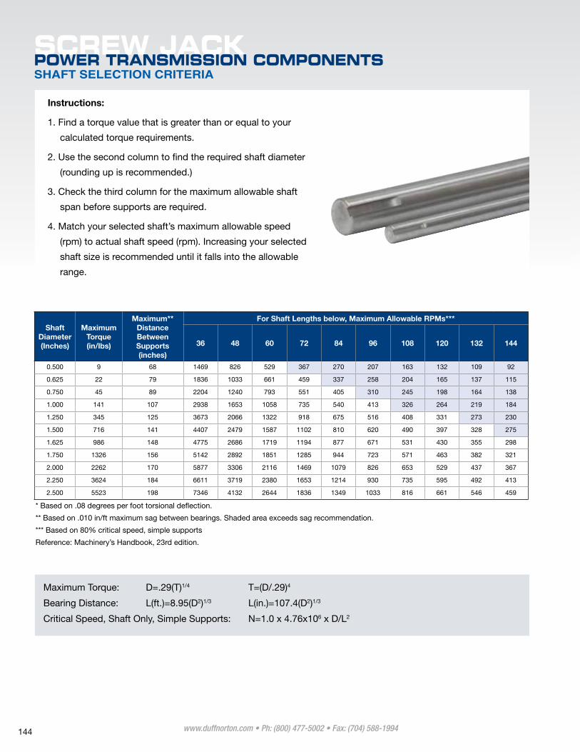
Instructions:
1. Find a torque value that is greater than or equal to your
calculated torque requirements.
2. Use the second column to find the required shaft diameter
(rounding up is recommended.)
3. Check the third column for the maximum allowable shaft
span before supports are required.
4. match your selected shaft’s maximum allowable speed
(rpm) to actual shaft speed (rpm). Increasing your selected
shaft size is recommended until it falls into the allowable
range.
Shaft Diameter (Inches)
Maximum Torque (in/lbs)
Maximum** Distance Between Supports (inches)
For Shaft Lengths below, Maximum Allowable RPMs***
36 48 60 72 84 96 108 120 132 144
0.500 9 68 1469 826 529 367 270 207 163 132 109 92
0.625 22 79 1836 1033 661 459 337 258 204 165 137 115
0.750 45 89 2204 1240 793 551 405 310 245 198 164 138
1.000 141 107 2938 1653 1058 735 540 413 326 264 219 184
1.250 345 125 3673 2066 1322 918 675 516 408 331 273 230
1.500 716 141 4407 2479 1587 1102 810 620 490 397 328 275
1.625 986 148 4775 2686 1719 1194 877 671 531 430 355 298
1.750 1326 156 5142 2892 1851 1285 944 723 571 463 382 321
2.000 2262 170 5877 3306 2116 1469 1079 826 653 529 437 367
2.250 3624 184 6611 3719 2380 1653 1214 930 735 595 492 413
2.500 5523 198 7346 4132 2644 1836 1349 1033 816 661 546 459
* Based on .08 degrees per foot torsional deflection.
** Based on .010 in/ft maximum sag between bearings. Shaded area exceeds sag recommendation.
*** Based on 80% critical speed, simple supports
Reference: machinery’s handbook, 23rd edition.
maximum Torque: D=.29(T)1/4 T=(D/.29)4
Bearing Distance: l(ft.)=8.95(D2)1/3 l(in.)=107.4(D2)1/3
Critical Speed, Shaft Only, Simple Supports: N=1.0 x 4.76x106 x D/l2
www.duffnorton.com • Ph: (800) 477-5002 • Fax: (704) 588-1994 144
ACTUATOR PILLOW BLOCKS
SCREW JACKPOWER TRANSMISSION COMPONENTS
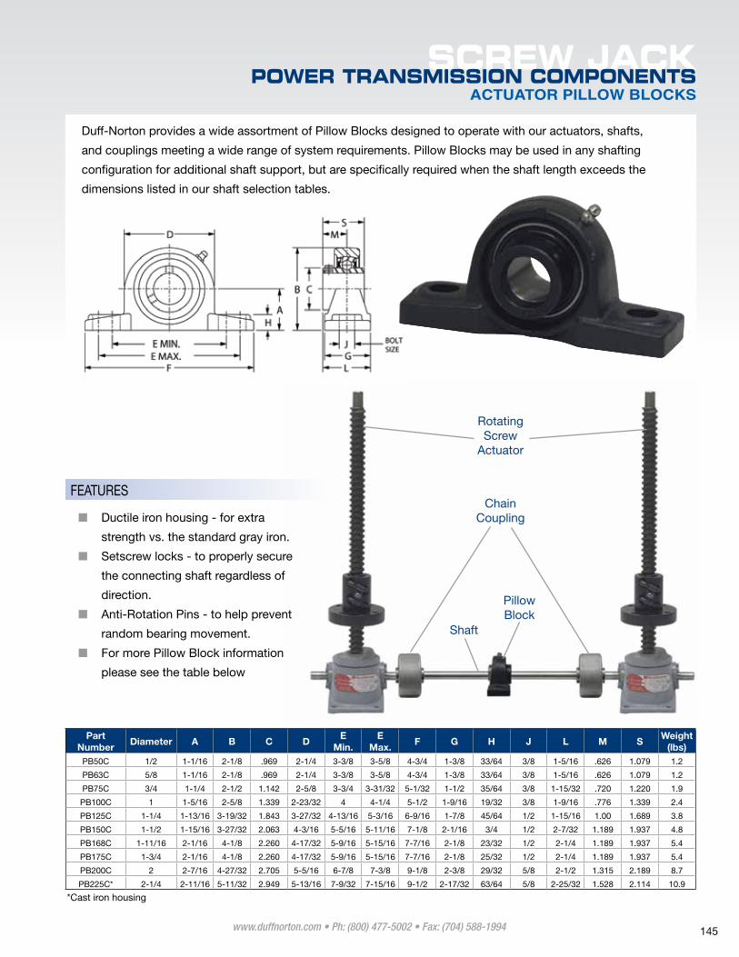
Duff-Norton provides a wide assortment of pillow Blocks designed to operate with our actuators, shafts,
and couplings meeting a wide range of system requirements. pillow Blocks may be used in any shafting
configuration for additional shaft support, but are specifically required when the shaft length exceeds the
dimensions listed in our shaft selection tables.
Chain Coupling
Shaft
pillow Block
Rotating Screw
Actuator
Part Number
Diameter A B C DE
Min.E
Max.F G H J L M S
Weight (lbs)
pB50C 1/2 1-1/16 2-1/8 .969 2-1/4 3-3/8 3-5/8 4-3/4 1-3/8 33/64 3/8 1-5/16 .626 1.079 1.2
pB63C 5/8 1-1/16 2-1/8 .969 2-1/4 3-3/8 3-5/8 4-3/4 1-3/8 33/64 3/8 1-5/16 .626 1.079 1.2
pB75C 3/4 1-1/4 2-1/2 1.142 2-5/8 3-3/4 3-31/32 5-1/32 1-1/2 35/64 3/8 1-15/32 .720 1.220 1.9
pB100C 1 1-5/16 2-5/8 1.339 2-23/32 4 4-1/4 5-1/2 1-9/16 19/32 3/8 1-9/16 .776 1.339 2.4
pB125C 1-1/4 1-13/16 3-19/32 1.843 3-27/32 4-13/16 5-3/16 6-9/16 1-7/8 45/64 1/2 1-15/16 1.00 1.689 3.8
pB150C 1-1/2 1-15/16 3-27/32 2.063 4-3/16 5-5/16 5-11/16 7-1/8 2-1/16 3/4 1/2 2-7/32 1.189 1.937 4.8
pB168C 1-11/16 2-1/16 4-1/8 2.260 4-17/32 5-9/16 5-15/16 7-7/16 2-1/8 23/32 1/2 2-1/4 1.189 1.937 5.4
pB175C 1-3/4 2-1/16 4-1/8 2.260 4-17/32 5-9/16 5-15/16 7-7/16 2-1/8 25/32 1/2 2-1/4 1.189 1.937 5.4
pB200C 2 2-7/16 4-27/32 2.705 5-5/16 6-7/8 7-3/8 9-1/8 2-3/8 29/32 5/8 2-1/2 1.315 2.189 8.7
pB225C* 2-1/4 2-11/16 5-11/32 2.949 5-13/16 7-9/32 7-15/16 9-1/2 2-17/32 63/64 5/8 2-25/32 1.528 2.114 10.9
*Cast iron housing
■■ Ductile iron housing - for extra
strength vs. the standard gray iron.
■■ Setscrew locks - to properly secure
the connecting shaft regardless of
direction.
■■ Anti-Rotation pins - to help prevent
random bearing movement.
■■ For more pillow Block information
please see the table below
FeATUReS
www.duffnorton.com • Ph: (800) 477-5002 • Fax: (704) 588-1994 145
SCREW JACKPOWER TRANSMISSION COMPONENTSACTUATOR FLANGE BLOCKS
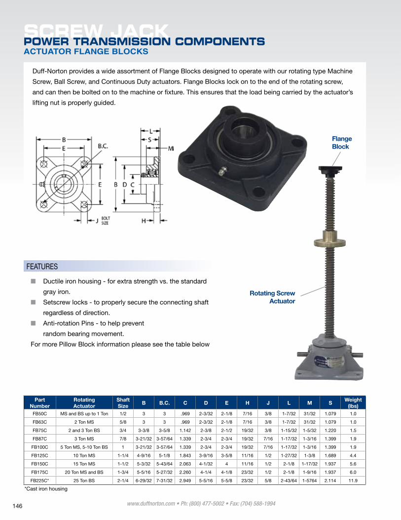
Duff-Norton provides a wide assortment of Flange Blocks designed to operate with our rotating type machine
Screw, Ball Screw, and Continuous Duty actuators. Flange Blocks lock on to the end of the rotating screw,
and can then be bolted on to the machine or fixture. This ensures that the load being carried by the actuator’s
lifting nut is properly guided.
Rotating Screw Actuator
Flange Block
Part Number
Rotating Actuator
Shaft Size
B B.C. C D E H J L M SWeight
(lbs)FB50C mS and BS up to 1 Ton 1/2 3 3 .969 2-3/32 2-1/8 7/16 3/8 1-7/32 31/32 1.079 1.0
FB63C 2 Ton mS 5/8 3 3 .969 2-3/32 2-1/8 7/16 3/8 1-7/32 31/32 1.079 1.0
FB75C 2 and 3 Ton BS 3/4 3-3/8 3-5/8 1.142 2-3/8 2-1/2 19/32 3/8 1-15/32 1-5/32 1.220 1.5
FB87C 3 Ton mS 7/8 3-21/32 3-57/64 1.339 2-3/4 2-3/4 19/32 7/16 1-17/32 1-3/16 1.399 1.9
FB100C 5 Ton mS, 5-10 Ton BS 1 3-21/32 3-57/64 1.339 2-3/4 2-3/4 19/32 7/16 1-17/32 1-3/16 1.399 1.9
FB125C 10 Ton mS 1-1/4 4-9/16 5-1/8 1.843 3-9/16 3-5/8 11/16 1/2 1-27/32 1-3/8 1.689 4.4
FB150C 15 Ton mS 1-1/2 5-3/32 5-43/64 2.063 4-1/32 4 11/16 1/2 2-1/8 1-17/32 1.937 5.6
FB175C 20 Ton mS and BS 1-3/4 5-5/16 5-27/32 2.260 4-1/4 4-1/8 23/32 1/2 2-1/8 1-9/16 1.937 6.0
FB225C* 25 Ton BS 2-1/4 6-29/32 7-31/32 2.949 5-5/16 5-5/8 23/32 5/8 2-43/64 1-5764 2.114 11.9
*Cast iron housing
■■ Ductile iron housing - for extra strength vs. the standard
gray iron.
■■ Setscrew locks - to properly secure the connecting shaft
regardless of direction.
■■ Anti-rotation pins - to help prevent
random bearing movement.
For more pillow Block information please see the table below
FeATUReS
www.duffnorton.com • Ph: (800) 477-5002 • Fax: (704) 588-1994 146
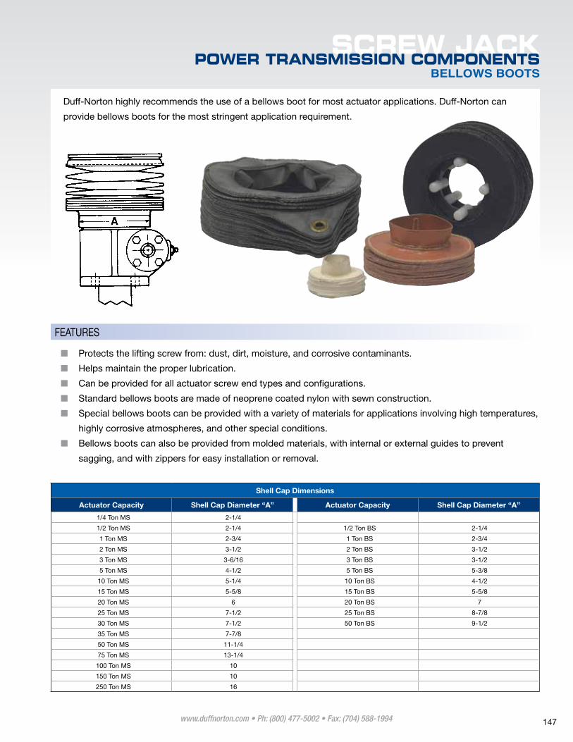
Duff-Norton highly recommends the use of a bellows boot for most actuator applications. Duff-Norton can
provide bellows boots for the most stringent application requirement.
BELLOWS BOOTS
SCREW JACKPOWER TRANSMISSION COMPONENTS
Shell Cap Dimensions
Actuator Capacity Shell Cap Diameter “A” Actuator Capacity Shell Cap Diameter “A”
1/4 Ton mS 2-1/4
1/2 Ton mS 2-1/4 1/2 Ton BS 2-1/4
1 Ton mS 2-3/4 1 Ton BS 2-3/4
2 Ton mS 3-1/2 2 Ton BS 3-1/2
3 Ton mS 3-6/16 3 Ton BS 3-1/2
5 Ton mS 4-1/2 5 Ton BS 5-3/8
10 Ton mS 5-1/4 10 Ton BS 4-1/2
15 Ton mS 5-5/8 15 Ton BS 5-5/8
20 Ton mS 6 20 Ton BS 7
25 Ton mS 7-1/2 25 Ton BS 8-7/8
30 Ton mS 7-1/2 50 Ton BS 9-1/2
35 Ton mS 7-7/8
50 Ton mS 11-1/4
75 Ton mS 13-1/4
100 Ton mS 10
150 Ton mS 10
250 Ton mS 16
■■ protects the lifting screw from: dust, dirt, moisture, and corrosive contaminants.
■■ helps maintain the proper lubrication.
■■ Can be provided for all actuator screw end types and configurations.
■■ Standard bellows boots are made of neoprene coated nylon with sewn construction.
■■ Special bellows boots can be provided with a variety of materials for applications involving high temperatures,
highly corrosive atmospheres, and other special conditions.
■■ Bellows boots can also be provided from molded materials, with internal or external guides to prevent
sagging, and with zippers for easy installation or removal.
FeATUReS
www.duffnorton.com • Ph: (800) 477-5002 • Fax: (704) 588-1994 147
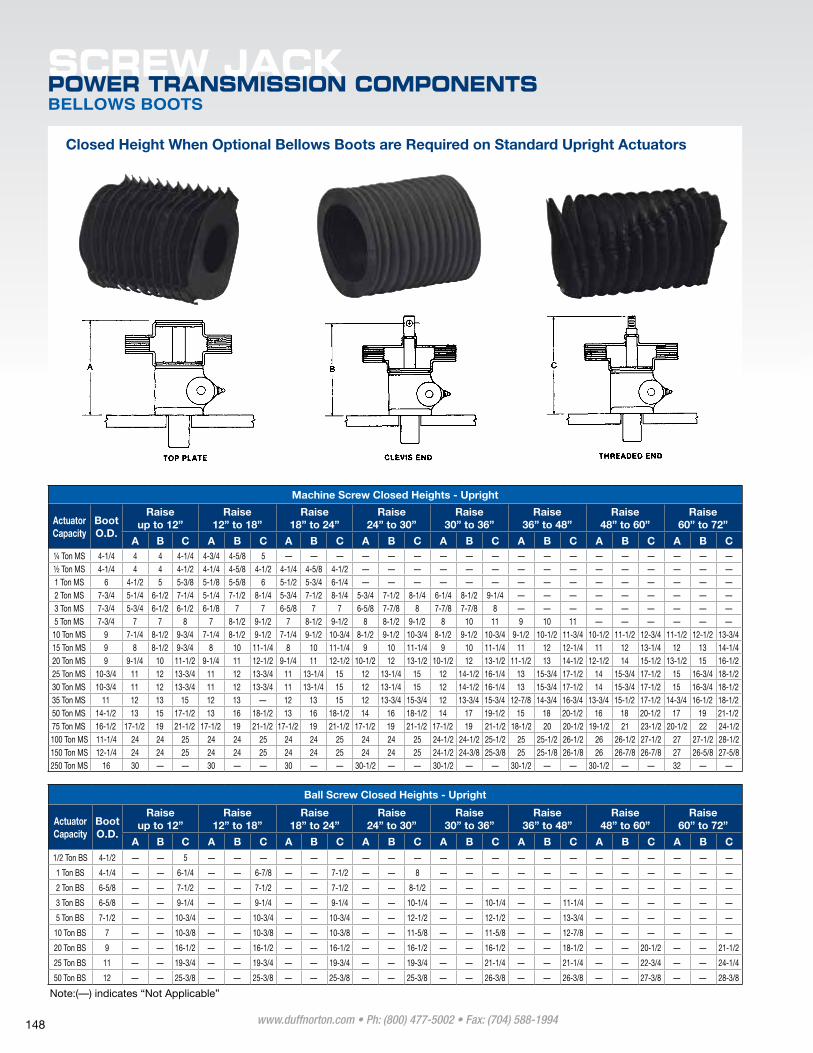
SCREW JACKPOWER TRANSMISSION COMPONENTSBELLOWS BOOTS
Closed Height When Optional Bellows Boots are Required on Standard Upright Actuators
Machine Screw Closed Heights - Upright
Actuator Capacity
Boot O.D.
Raiseup to 12”
Raise 12” to 18”
Raise 18” to 24”
Raise 24” to 30”
Raise 30” to 36”
Raise 36” to 48”
Raise 48” to 60”
Raise 60” to 72”
A B C A B C A B C A B C A B C A B C A B C A B C¼ Ton mS 4-1/4 4 4 4-1/4 4-3/4 4-5/8 5 — — — — — — — — — — — — — — — — — —½ Ton mS 4-1/4 4 4 4-1/2 4-1/4 4-5/8 4-1/2 4-1/4 4-5/8 4-1/2 — — — — — — — — — — — — — — —1 Ton mS 6 4-1/2 5 5-3/8 5-1/8 5-5/8 6 5-1/2 5-3/4 6-1/4 — — — — — — — — — — — — — — —2 Ton mS 7-3/4 5-1/4 6-1/2 7-1/4 5-1/4 7-1/2 8-1/4 5-3/4 7-1/2 8-1/4 5-3/4 7-1/2 8-1/4 6-1/4 8-1/2 9-1/4 — — — — — — — — —3 Ton mS 7-3/4 5-3/4 6-1/2 6-1/2 6-1/8 7 7 6-5/8 7 7 6-5/8 7-7/8 8 7-7/8 7-7/8 8 — — — — — — — — —5 Ton mS 7-3/4 7 7 8 7 8-1/2 9-1/2 7 8-1/2 9-1/2 8 8-1/2 9-1/2 8 10 11 9 10 11 — — — — — —
10 Ton mS 9 7-1/4 8-1/2 9-3/4 7-1/4 8-1/2 9-1/2 7-1/4 9-1/2 10-3/4 8-1/2 9-1/2 10-3/4 8-1/2 9-1/2 10-3/4 9-1/2 10-1/2 11-3/4 10-1/2 11-1/2 12-3/4 11-1/2 12-1/2 13-3/415 Ton mS 9 8 8-1/2 9-3/4 8 10 11-1/4 8 10 11-1/4 9 10 11-1/4 9 10 11-1/4 11 12 12-1/4 11 12 13-1/4 12 13 14-1/420 Ton mS 9 9-1/4 10 11-1/2 9-1/4 11 12-1/2 9-1/4 11 12-1/2 10-1/2 12 13-1/2 10-1/2 12 13-1/2 11-1/2 13 14-1/2 12-1/2 14 15-1/2 13-1/2 15 16-1/225 Ton mS 10-3/4 11 12 13-3/4 11 12 13-3/4 11 13-1/4 15 12 13-1/4 15 12 14-1/2 16-1/4 13 15-3/4 17-1/2 14 15-3/4 17-1/2 15 16-3/4 18-1/230 Ton mS 10-3/4 11 12 13-3/4 11 12 13-3/4 11 13-1/4 15 12 13-1/4 15 12 14-1/2 16-1/4 13 15-3/4 17-1/2 14 15-3/4 17-1/2 15 16-3/4 18-1/235 Ton mS 11 12 13 15 12 13 — 12 13 15 12 13-3/4 15-3/4 12 13-3/4 15-3/4 12-7/8 14-3/4 16-3/4 13-3/4 15-1/2 17-1/2 14-3/4 16-1/2 18-1/250 Ton mS 14-1/2 13 15 17-1/2 13 16 18-1/2 13 16 18-1/2 14 16 18-1/2 14 17 19-1/2 15 18 20-1/2 16 18 20-1/2 17 19 21-1/275 Ton mS 16-1/2 17-1/2 19 21-1/2 17-1/2 19 21-1/2 17-1/2 19 21-1/2 17-1/2 19 21-1/2 17-1/2 19 21-1/2 18-1/2 20 20-1/2 19-1/2 21 23-1/2 20-1/2 22 24-1/2100 Ton mS 11-1/4 24 24 25 24 24 25 24 24 25 24 24 25 24-1/2 24-1/2 25-1/2 25 25-1/2 26-1/2 26 26-1/2 27-1/2 27 27-1/2 28-1/2150 Ton mS 12-1/4 24 24 25 24 24 25 24 24 25 24 24 25 24-1/2 24-3/8 25-3/8 25 25-1/8 26-1/8 26 26-7/8 26-7/8 27 26-5/8 27-5/8250 Ton mS 16 30 — — 30 — — 30 — — 30-1/2 — — 30-1/2 — — 30-1/2 — — 30-1/2 — — 32 — —
Ball Screw Closed Heights - Upright
Actuator Capacity
Boot O.D.
Raise up to 12”
Raise 12” to 18”
Raise 18” to 24”
Raise 24” to 30”
Raise 30” to 36”
Raise 36” to 48”
Raise 48” to 60”
Raise 60” to 72”
A B C A B C A B C A B C A B C A B C A B C A B C1/2 Ton BS 4-1/2 — — 5 — — — — — — — — — — — — — — — — — — — — —
1 Ton BS 4-1/4 — — 6-1/4 — — 6-7/8 — — 7-1/2 — — 8 — — — — — — — — — — — —
2 Ton BS 6-5/8 — — 7-1/2 — — 7-1/2 — — 7-1/2 — — 8-1/2 — — — — — — — — — — — —
3 Ton BS 6-5/8 — — 9-1/4 — — 9-1/4 — — 9-1/4 — — 10-1/4 — — 10-1/4 — — 11-1/4 — — — — — —
5 Ton BS 7-1/2 — — 10-3/4 — — 10-3/4 — — 10-3/4 — — 12-1/2 — — 12-1/2 — — 13-3/4 — — — — — —
10 Ton BS 7 — — 10-3/8 — — 10-3/8 — — 10-3/8 — — 11-5/8 — — 11-5/8 — — 12-7/8 — — — — — —
20 Ton BS 9 — — 16-1/2 — — 16-1/2 — — 16-1/2 — — 16-1/2 — — 16-1/2 — — 18-1/2 — — 20-1/2 — — 21-1/2
25 Ton BS 11 — — 19-3/4 — — 19-3/4 — — 19-3/4 — — 19-3/4 — — 21-1/4 — — 21-1/4 — — 22-3/4 — — 24-1/4
50 Ton BS 12 — — 25-3/8 — — 25-3/8 — — 25-3/8 — — 25-3/8 — — 26-3/8 — — 26-3/8 — — 27-3/8 — — 28-3/8
Note:(—) indicates “Not Applicable”
www.duffnorton.com • Ph: (800) 477-5002 • Fax: (704) 588-1994 148
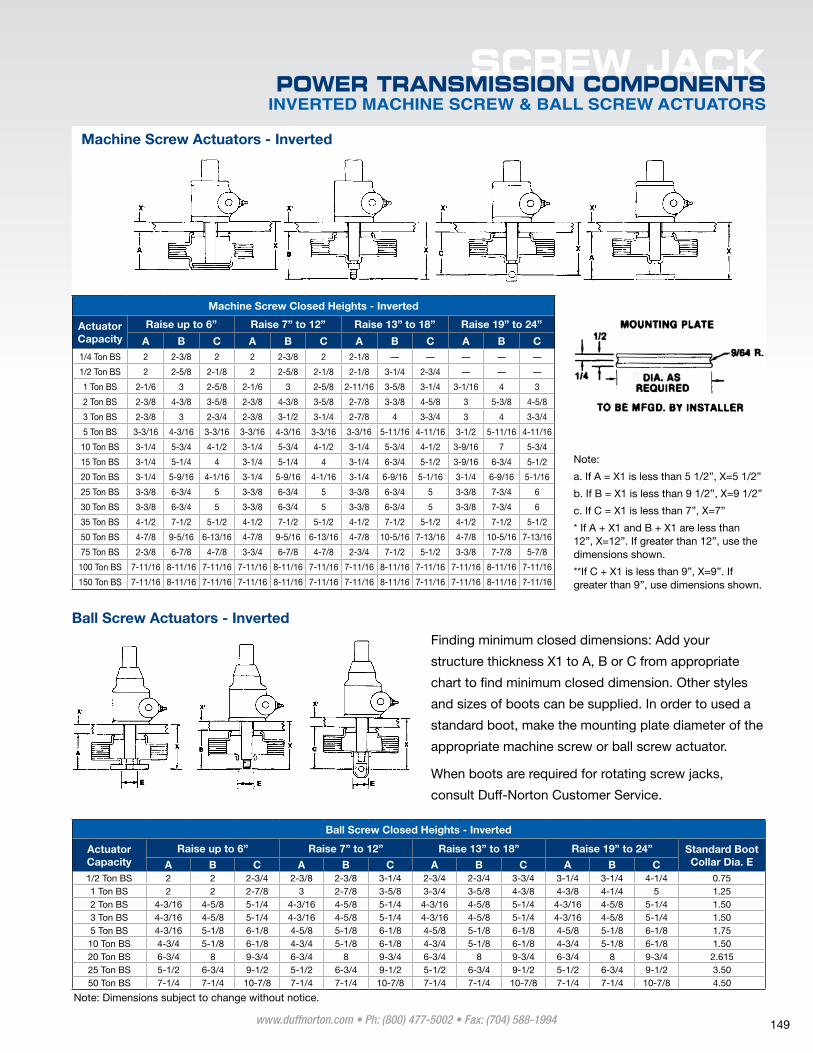
INVERTED MACHINE SCREW & BALL SCREW ACTUATORS
SCREW JACKPOWER TRANSMISSION COMPONENTS
Ball Screw Actuators - InvertedFinding minimum closed dimensions: Add your
structure thickness X1 to A, B or C from appropriate
chart to find minimum closed dimension. Other styles
and sizes of boots can be supplied. In order to used a
standard boot, make the mounting plate diameter of the
appropriate machine screw or ball screw actuator.
When boots are required for rotating screw jacks,
consult Duff-Norton Customer Service.
Note: Same values can be used for 4800 and 9400 series actuator units.
Machine Screw Closed Heights - Inverted
Actuator Capacity
Raise up to 6” Raise 7” to 12” Raise 13” to 18” Raise 19” to 24”
A B C A B C A B C A B C1/4 Ton BS 2 2-3/8 2 2 2-3/8 2 2-1/8 — — — — —
1/2 Ton BS 2 2-5/8 2-1/8 2 2-5/8 2-1/8 2-1/8 3-1/4 2-3/4 — — —
1 Ton BS 2-1/6 3 2-5/8 2-1/6 3 2-5/8 2-11/16 3-5/8 3-1/4 3-1/16 4 3
2 Ton BS 2-3/8 4-3/8 3-5/8 2-3/8 4-3/8 3-5/8 2-7/8 3-3/8 4-5/8 3 5-3/8 4-5/8
3 Ton BS 2-3/8 3 2-3/4 2-3/8 3-1/2 3-1/4 2-7/8 4 3-3/4 3 4 3-3/4
5 Ton BS 3-3/16 4-3/16 3-3/16 3-3/16 4-3/16 3-3/16 3-3/16 5-11/16 4-11/16 3-1/2 5-11/16 4-11/16
10 Ton BS 3-1/4 5-3/4 4-1/2 3-1/4 5-3/4 4-1/2 3-1/4 5-3/4 4-1/2 3-9/16 7 5-3/4
15 Ton BS 3-1/4 5-1/4 4 3-1/4 5-1/4 4 3-1/4 6-3/4 5-1/2 3-9/16 6-3/4 5-1/2
20 Ton BS 3-1/4 5-9/16 4-1/16 3-1/4 5-9/16 4-1/16 3-1/4 6-9/16 5-1/16 3-1/4 6-9/16 5-1/16
25 Ton BS 3-3/8 6-3/4 5 3-3/8 6-3/4 5 3-3/8 6-3/4 5 3-3/8 7-3/4 6
30 Ton BS 3-3/8 6-3/4 5 3-3/8 6-3/4 5 3-3/8 6-3/4 5 3-3/8 7-3/4 6
35 Ton BS 4-1/2 7-1/2 5-1/2 4-1/2 7-1/2 5-1/2 4-1/2 7-1/2 5-1/2 4-1/2 7-1/2 5-1/2
50 Ton BS 4-7/8 9-5/16 6-13/16 4-7/8 9-5/16 6-13/16 4-7/8 10-5/16 7-13/16 4-7/8 10-5/16 7-13/16
75 Ton BS 2-3/8 6-7/8 4-7/8 3-3/4 6-7/8 4-7/8 2-3/4 7-1/2 5-1/2 3-3/8 7-7/8 5-7/8
100 Ton BS 7-11/16 8-11/16 7-11/16 7-11/16 8-11/16 7-11/16 7-11/16 8-11/16 7-11/16 7-11/16 8-11/16 7-11/16
150 Ton BS 7-11/16 8-11/16 7-11/16 7-11/16 8-11/16 7-11/16 7-11/16 8-11/16 7-11/16 7-11/16 8-11/16 7-11/16
Ball Screw Closed Heights - Inverted
Actuator Capacity
Raise up to 6” Raise 7” to 12” Raise 13” to 18” Raise 19” to 24” Standard Boot Collar Dia. EA B C A B C A B C A B C
1/2 Ton BS 2 2 2-3/4 2-3/8 2-3/8 3-1/4 2-3/4 2-3/4 3-3/4 3-1/4 3-1/4 4-1/4 0.751 Ton BS 2 2 2-7/8 3 2-7/8 3-5/8 3-3/4 3-5/8 4-3/8 4-3/8 4-1/4 5 1.252 Ton BS 4-3/16 4-5/8 5-1/4 4-3/16 4-5/8 5-1/4 4-3/16 4-5/8 5-1/4 4-3/16 4-5/8 5-1/4 1.503 Ton BS 4-3/16 4-5/8 5-1/4 4-3/16 4-5/8 5-1/4 4-3/16 4-5/8 5-1/4 4-3/16 4-5/8 5-1/4 1.505 Ton BS 4-3/16 5-1/8 6-1/8 4-5/8 5-1/8 6-1/8 4-5/8 5-1/8 6-1/8 4-5/8 5-1/8 6-1/8 1.7510 Ton BS 4-3/4 5-1/8 6-1/8 4-3/4 5-1/8 6-1/8 4-3/4 5-1/8 6-1/8 4-3/4 5-1/8 6-1/8 1.5020 Ton BS 6-3/4 8 9-3/4 6-3/4 8 9-3/4 6-3/4 8 9-3/4 6-3/4 8 9-3/4 2.61525 Ton BS 5-1/2 6-3/4 9-1/2 5-1/2 6-3/4 9-1/2 5-1/2 6-3/4 9-1/2 5-1/2 6-3/4 9-1/2 3.5050 Ton BS 7-1/4 7-1/4 10-7/8 7-1/4 7-1/4 10-7/8 7-1/4 7-1/4 10-7/8 7-1/4 7-1/4 10-7/8 4.50
Note: Dimensions subject to change without notice.
Note:
a. If A = X1 is less than 5 1/2”, X=5 1/2”
b. If B = X1 is less than 9 1/2”, X=9 1/2”
c. If C = X1 is less than 7”, X=7”
* If A + X1 and B + X1 are less than 12”, X=12”. If greater than 12”, use the dimensions shown.
**If C + X1 is less than 9”, X=9”. If greater than 9”, use dimensions shown.
Machine Screw Actuators - Inverted
www.duffnorton.com • Ph: (800) 477-5002 • Fax: (704) 588-1994 149