Embed Size (px)
Citation preview
GEK-14992D
INSTRUCTIONS
3S7932lA100, LAlOl, LA102, LA103 POWER SYSTEM STABILIZER
INTRODUCTION
This Supplementary Control Panel equipment is de- signed for siding system stability by introducing a supplementary control panel signal into a continuously acting voltage regulator equipment which is already installed on steam driven or hydro driven generators. The control may also be furnished with new excitation controls. This control can be supplied to operate with General Electric generator excitation systems consist- ing of a rotating exciter controlled by regulators of the rotating amplifier or static type.
The equipment will supplement the conventional volt- age regulator control with a control function derived so that, under deviations in machine speed or load, excrtation becomes regulated as a composite function of voltage and some other appropriate quantity such as speed.
This supplementary control panel equipment includes the functions of input transducer (not including shaft- mounted tachometers on units using speed as a sup- plementary control panel signal), signal conditioning, limiting, and provisions for addition or injection of the signal into the appropriate type of conventional voltage regulator.
The signal conditioning transfer function applied to the input variable by the signal conditioning portion will be of the form:
RECEIVING AND HANDLING
Immediately upon receipt, the equipment should be carefully unpacked to avoid damage. As soon as the equipment is unpacked, it should be examined for any damage that may have been sustained in transit.
@ CopyrIght General Electric Company. USA 1971
If injury or rough handling is evident, a damage claim should be flied immediately with the transporatlon company and the nearest General Electric Sales Office should be notified promptly.
FUNCTIONAL DESCRIPTION
SPEED INPUT TRANSDUCER
For supplementary control panel equipment operating from shaft speed, a signal from a turbine-mounted tachometer is required for input to the power system stabilizer. This speed signal input shall be,three- phase AC, not less than 90 hertz and 35 volts rms at generator rated speed, with linear voltage variation near rated speed.
An input circuit for accepting the speed (tachometer output) signal will be furnished in the supplementary control panel.
Modulation and noise content of the input signal to the supplementary control equipment must be below the level which would produce a change of more than 0.1% in the output to the voltage regulator.
FREQUENCY INPUT TRANSDUCER
For supplementary control panel equipment operating with hydrogenerator regulators, a frequency input signal will be used for stabilizing. A frequency transducer is included with the supplementary control panel to operate from the user’s three-phase potential transformer secondary. The input may be from the same potential transformer circuit that supplies the generator voltage signal to the voltage regulator.
The transducer output will be accurate over a range between 59.5 and 60.5 hertz. Any associated filter- ing is compatible with the required characteristics of the supplementary control panel.
These insfrucfions do not purport fo cover all defarls or variafions in equrpmenf nor to provrde for every possrbfe confrngency to be met m connecfron wfh insfalkaflon, operafron or mainfenance. Should furfher informafion be desired or should parfrcular problems arose which are not covered suffrcienfly for the purchaser’s purposes, the matter should be referred fo the General Fleck Company.
GENERAL@ ELECTRIC
Supplementary Control Panel GEK-14992
Modulation and noise content of the input signal to the frequency transducer must be below the level which would produce a change of more than 0.1% in the out- put of the supplementary control panel.
SIGNAL CONDITIONING
The signal conditioning function will take its input from the transducer and provide an output that is a function of the deviation in the input signal.
The signal conditionme; function is capable of process- ing signals from the input transducer that vary at fre- quencies from approximately 1 cycle/minute to 80 cycles/minute.
The signal conditioning function will apply the follow- ing transfer function to modify the sensed variable signal for insertion into the voltage regulator:
K @IS) (l+T2S) (l+TlS) (l+T3S)
Adjustments are provided to vary the parameters of the signal conditioning function so as to permit com- pensation for the variations m the characteristics of the regulator, excitation system, and generator to which it is applied. These adjustments can be made by calibrated dial settings which will be accurate to within 10% of the desired parameter value.
The adjustments are capable of modifying the transfer function parameters through the following typical ranges:
K = 2 to 100 (in per umt)
Tl = 0.1 to 50 seconds
T2 = 0.2 to 1.5 seconds
T3 = 0.02 to 0.1 second
T4 = 0.2 to 1.5 seconds
T5 = 0.02 through 0.1 second
The signal conditioning equipment will reset to zero, and wash out or otherwise eliminate output signals that may occur because of a long time deviation in input signal level or due to drift that exists for longer than a period of approximately 1 cycle/minute.
LIMITING
Limiting is provided in the supplementary control panel equipment so that the output signal will not completely override voltage regulating action. Limiting will be
such as to prevent supplementary control panel output from causing changes in voltage regulator output that would exceed preset limits. This limit will be of the clamping or “wind-up” type which will hold the sup- plementary control output at the preset limit value whenever the input signal is such as to produce an unlimited output equal to or greater than the limit setting . The amount of limiting is adjusted by a calibrated dial between &2% and lo%, corresponding to limiting the effect on voltage regulator output to that which the same % voltage error would have.
OUTPUT --
The supplementary control panel equipment has in- cluded provisions for the insertion of its output into the amplifier circuitry of the voltage regulator by a means suitable for the type of regulator with which the supplementary control panel is to be used.
The supplementary control panel equipment includes a relay for disconnecting its output from the voltage regulator. This relay can be controlled by an “OFF- ON” momentary contact or switch located on the supplementary control panel and through a set of terminal points to which the user can connect logic of his choice for removing the supplementary control panel signal from regulator control.
The output relay will also be controlled by a circuit which will operate to disconnect the supplementary control panel from the voltage regulator if the sup- plementary control panel output goes into the limit and remains to Limit for longer than a preset time (adjustable from 2 to 60 seconds).
A zero-center meter is furnished on the panel to indicate supplementary control panel output. A re- mote high impedance (2000 ohms/volt) meter may be added in parallel for remote indication.
APPLICATION
The supplementary control panel equipment described herein is designed for operation only with voltage regulators of the continuous-acting type manufac- tured by the General Electric Company,
Each voltage regulator will required a correspond- ing separate supplementary control panel. The control is not designed to be compatible with more than one regulator unit.
2’
Supplementary Control Panel GEK-14992
EQUIPMENT DESCRIPTION Signal Input
GENERAL
The supplementary control panel circuitry is furnished with static components with the exception of adjustable devices and relays required for switching the output.
For the speed signal, use a three-conductor shielded lead from the tachometer to the control panel. Tie the shield to common atthe control panel.
Circuit components are conservatively rated and are protected against harmful transients which might occur. The equipment is designed to operate satisfactorily in ambient temperatures from -10°C to +55”C without auxiliary cooling equipment.
For the frequency signal, use a three-conductor shielded lead from the potential transformer secon- daries to the control panel (100 - 130 volt).
Auxiliary Power -
Use two leads for single phase AC input power (500 vo It amps).
Where practical, electronic circuit components are assembled on modular printed-circuit boards, each with its individual terminal block located at the front of the board for off-board connections.
Output to Regulator
POWER SUPPLY
Use a two-conductor lead for transmitting the power system stabilizer signal from the panel to the regula- tor amplifier circuit. The lead should be shielded if the distance is over 10 feet.
Each supplementary control panel equipment is furnished with its own power supply, arranged to utilize power from the same AC source that supplied auxiliary power to the voltage regulator. Maximum power requirement will be 500 VA, single-phase, 60 Hz, 230, 460, or 575 volts.
Permissive Contact
INSTALLATION
A permissive contact (N. 0. ) from the line breaker is required to permit the supplementary Control pans1 signal to modulate the excitation only while the gen- erator is connected to the load. The speed may vary several percent with the machine disconnected from the system and should not modulate the excitation.
MOUNTING Remote Control (Optional)
The supplementary control panel equipment will be furnished completely mounted and wired on a steel panel. All connections will be made at the front with components and connections arranged for maximum accessibility.
The panel will be mounted and wired with the regulator, when ordered with new excitation controls.
The panel may be furnished (for existing regulators) mounted in a rigid, self-supporting sheet steel NEMA I, indoor enclosure with full length, hinged front door. Louvered openings will be provided as required for pro- per coolmg. This enciosure ~111 be suitable for either floor or wall mounting.
Local control and indication are provided. A three- conductor lead is required for remote ON, OFF con- trol and a two-conductor lead is required for an ON indicating light. A two-conductor lead is required for an alarm from the time delay relay contact. A two-conductor lead is necessary from the output to a remote mdicatmg meter (2000 ohm per volt). (Scale 10-O-10 volts)
SETTINGS AND ADJUSTMENTS
Approximate dimensions of the enclosure will be 60 inches high by 28 inches wide by 18 inches deep. An additional 14 inches is required for the door opening.
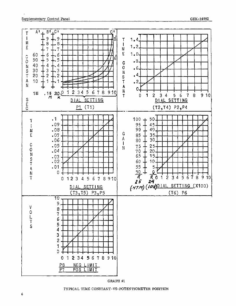
The time constants can be set with the potentiometer using Graph 1. A typical reference is the element- ary diagram (Figure 1).
An arbitrary set of time constants with gain and phase iS plotted against radians as shown on Graphs 2 and 3.
INTERCONNECTIONS
A very high AC gain is developed in this panel and care must be used m connect- ing the input signal. The AC gain will change with a change in time constant. Refer to the following recommendations.
The adjustments are best derived from an analytical group or from the General Electric Company. Con- tact your local Sales Office. A paper, “Concepts of Synchronous Machine Stability as Affected by Exci- tation Control”, by F. P. deMello and C. Concordia may also be used as a reference (68TP129PWR).
Supplementary Control Panel GEK-14992
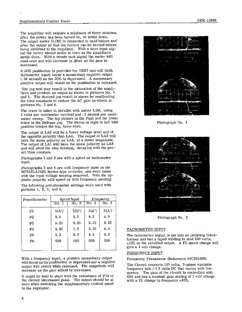
The amplifier will require a minimum of three minutes, after the power has been turned on, to settle down. The output meter (LlM) is connected to read before and after the output so that the control can be zeroed before being switched to the regulator. With a zero input sig- nal the meter should settle to zero as the amplifiers settle down. With a steady tach signal the meter will read zero and will increase in jitter as the gam is increased. A JOG pushbutton is provided for TEST and will (with tachometer input) cause a momentary negative output (. 04 second) as the JOG is depressed. A momentary positive output will result as the pushbutton is released.
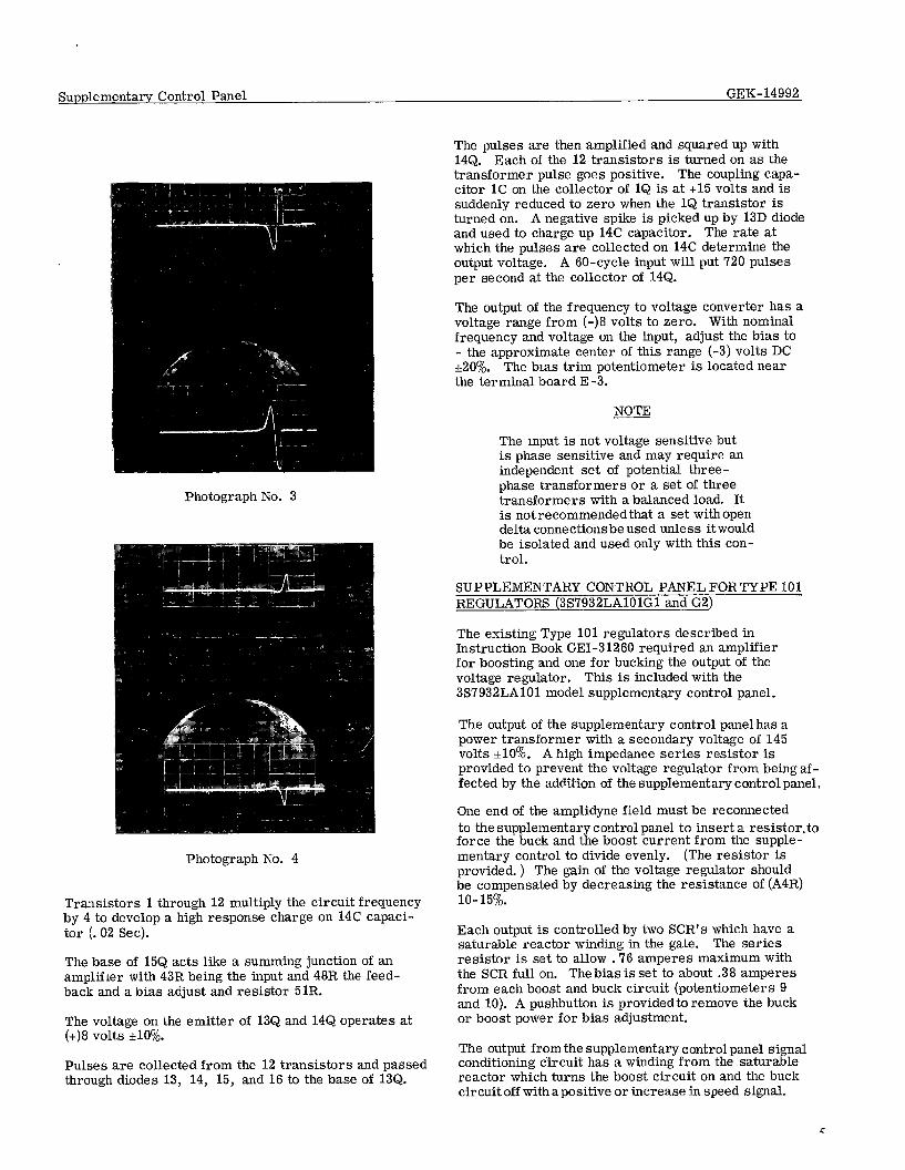
The jog test may result in the saturation of the ampli- fiers and produce an output as shown in pictures No. 1 and 3. The desired jog result is shown by readjusting the time constants to reduce the AC gain as shown in pictures No. 2 and 4.
The trace is taken in parallel with meter LlM, using 5 volts per centimeter vertical and .5 second per centi- meter sweep. The top picture is the Push and the lower trace is the Release log. The sweep is right to left with positive toward the top, from zero.
The output of LA3 will be a lower voltage level and of the opposite polarity than LA4. The output of LA2 will have the same polarity as LA4, at a lower magnitude. The output of LA1 will have the same polarity as LA3 and will show the step function, decaying with the pre- set time constant.
Photographs 1 and 2 are with a speed or tachometer input.
Photographs 3 and 4 are with frequency input on the 3S7932LA102G Series type controls, and were taken with the input voltage sensing removed. Note the op- posite polarity with speed or with frequency sensing.
The following potentiometer settings were used with pictures 1, 2, 3, and 4.
potentiometer l-
Pl
P2
P3
P4
P5
P6
Speed I Input No. 2
503’) 1. 5
9.35
1. 5 9. 3
030
Fref No. 3
p lency No. 4
5(A’) 5(A’) 9.3 4. 0
9.35 9. 35
9.35 4.0 9.3 9.3
030 030
With a frequency input, a positive momentary output will occur as the pushbutton is depressed and a negative output will result when released. The magnitude will increase as the gain adjust is mcreased.
It might be well to start with the resistance of PI4 in the circuit (decreased gain). The output should be at zero when switching the supplementary control panel to the regulator.
Photograph No. 1
Photograph No. 2
TACHOMETER INPUT
The tachometer signal is put into an isolating trans- former and has a taped winding to hold 100 volts, rtlO% on the rectified output. A 1% speed change will give a 1 volt change.
FREQUENCY INPUT
Frequency Transducer (Reference 44C301602) The Circuit converts 115 volts, J-phase variable frequency into (-) 3 volts DC that varies with fre- quency. The gain of the circuit is controlled with 48R and has a. nominal gain setting of 1 volt change with a 1% change in frequency *lo’?&.
4
Supplementary Control Panel
Photograph No. 3
Photograph No. 4
Transistors 1 through 12 multiply the circuit frequency by 4 to develop a high response charge on 14C capaci- tor (. 02 Set).
The base of 15Q acts like a summing junction of an amplifier with 43R being the input and 48R the feed- back and a bias adjust and resistor 5lR.
The voltage on the emitter of 13Q and 14Q operates at (+)8 volts *lO%J.
Pulses are collected from the 12 transistors and passed through diodes 13, 14, 15, and 16 to the base of 13Q.
GEK- 14992
The pulses are then amplified and squared up with 14Q. Each of the 12 transistors is turned on as the transformer pulse goes positive. The coupling capa- citor 1C on the collector of 1Q is at +15 volts and is suddenly reduced to zero when the 1Q transistor is turned on. A negative spike is picked up by 13D diode and used to charge up 14C capacitor. The rate at which the pulses are collected on 14C determine the output voltage. A 60-cycle input will put 720 pulses per second at the collector of 14Q.
The output of the frequency to voltage converter has a voltage range from (-)8 volts to zero. With nominal frequency and voltage on the input, adjust the bias to - the approximate center of this range (-3) volts DC &200/o. The bras trim potentiometer is located near the terminal board E-3.
NOTE
The input is not voltage sensitive but is phase sensitive and may require an independent set of potential three- phase transformers or a set of three transformers with a balanced load. It is not recommended that a set withopen delta connectionsbe used unless itwould be isolated and used only with this con- trol.
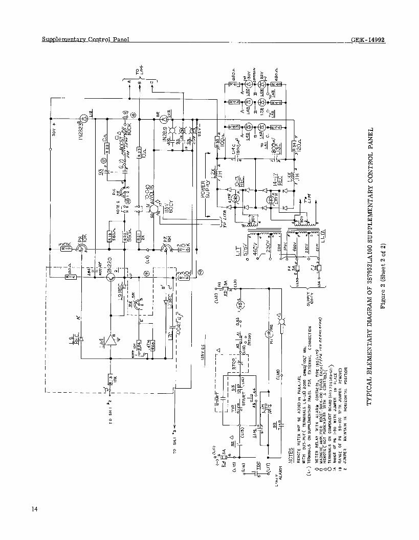
SUPPLEMENTARY CONTROL PANEL FORTYPE 101 REGULATORS (3S7932LAlOlGl and G2)
The existing Type 101 regulators described in Instruction Book GEI-31260 required an amplifier for boosting and one for bucking the output of the voltage regulator. This is included with the 3S7932LAlOl model supplementary control panel.
The output of the supplementary control panel has a power transformer with a secondary voltage of 145 volts *lo’%. A high impedance series resistor is provided to prevent the voltage regulator from being af- fected by the addition of the supplementary control panel,
One end of the amplidyne field must be reconnected to the supplementary control panel to insert a resistor,to force the buck and the boost current from the supple- mentary control to divide evenly. (The resistor is provided. ) The gain of the voltage regulator should be compensated by decreasing the resistance of (A4R) lo- 15%.
Each output is controlled by two SCR’s which have a saturable reactor winding in the gate. The series resistor is set to allow .76 amperes maximum with the SCR full on. The bias is set to about .38 amperes from each boost and buck circuit (potentiometers 9 and 10). A pushbutton is provided to remove the buck or boost power for bias adjustment.
The output from the supplementary control panel signal conditioning circuit has a winding from the saturable reactor which turns the boost circuit on and the buck circuit off with a positive or increase in speed signal.
Supplementary Control Panel GEK-14992
12 34 5 678 91C
T 1 M E
.I
.OY .08 .07 .06 .05 .04 .03 .02 . 0'1
0 0123 4 5 6 7 891C
DIAL SETTING (T3,T5) P3,P5
4i-l IU
9
7” 6
4” 3 2 I 0 .., . . . .
0 12 34 56 78 91(
P8 NEG LiMlT P7 POS LIMIT
DIAL SETTING (T2,T4) P2,P4
D I AL SETTI NG (X100)
GRAPH #1
TYPICAL TIME CONSTANT-W-POTENTIOMETER POSITION 6

Supplementary Control Panel GEK-14992
GRAPH #2
60
50
40
30
20
IO
0
-10
RADIANS/SEcOND
GRAPH #3
LEAD
100
80
60
P H A 40 S E
20
0
FiADIANS/SECOND
Supplementary Control Panel GEK-14992
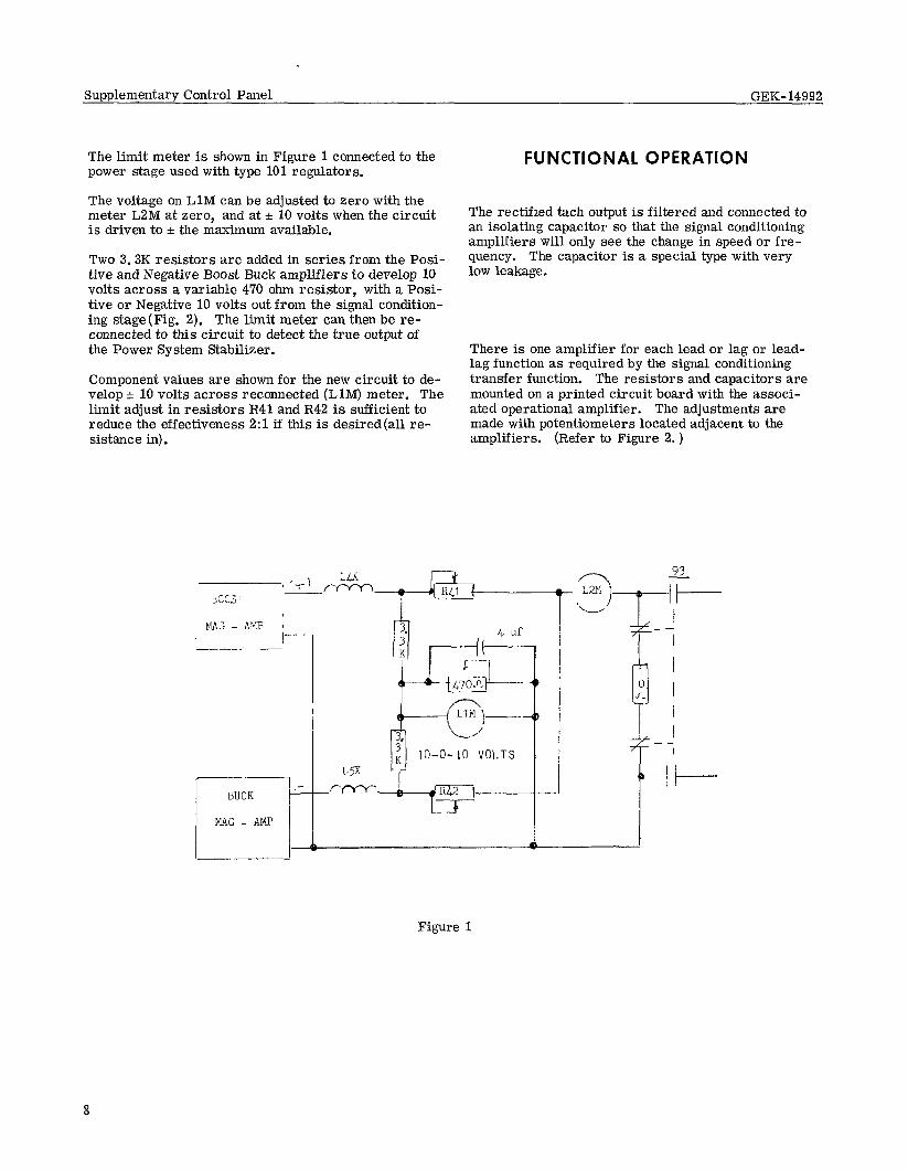
The limit meter is shown in Figure 1 connected to the power stage used with type 101 regulators.
The voltage on LlM can be adjusted to zero with the meter LZM at zero, and at f 10 volts when the circuit is driven to & the maximum available.
Two 3.3K resistors are added in series from the Posi- tive and Negative Boost Buck amplifiers to develop 10 volts across a variable 470 ohm resistor, with a Posi- tive or Negative 10 volts out from the signal condition- ing stage (Fig. 2). The limit meter can then be re- connected to this circuit to detect the true output of the Power System Stabilizer.
Component values are shown for the new circuit to de- velop f 10 volts across reconnected (LlM) meter. The limit adjust in resistors R41 and R42 is sufficient to reduce the effectiveness 2:l if this is desired(al1 re- sistance in).
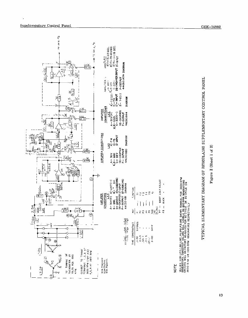
FUNCTIONAL OPERATION
The rectified tach output is filtered and connected to an isolating capacitor so that the signal conditioning amplifiers will only see the change in speed or fre- quency. The capacitor is a special type with very low leakage.
There is one amplifier for each lead or lag or lead- lag function as required by the signal conditioning transfer function. The resistors and capacitors are mounted on a printed circuit board with the associ- ated operational amplifier. The adjustments are made with potentiometers located adjacent to the amplifiers. (Refer to Figure 2. )
Figure 1

SuppIementa-iy ControI Panel GEK-14992
There are three ranges for Tl function with 30% over- lap between ranges. The range is selected by changing the connection to the proper terminal. (Refer to Figure 2 and Graph 1. )
There are two ranges for gam (K). The equipment is furnished with a jumper on the gain amplifier board which puts the gain in the low range (l-50). The jumper is located on the amplifier board just back of the termi- nal board. Removing the jumper will give 50-100 range on gain.
The adjustment of the Twin-T filter on frequency sen- sing controls or hydro driven controls may vary. Refer to note under frequency input. These units will be furnished with 30 Hz adjusted Twin-T filter but may be changed as needed. Calculations may be made as follows. Wo = resonant frequency required for attenuation.
An increase in speed or frequency will give the regulator a signal to increase the excitation.
GAIN
Decreasmg the tuned frequency will cut into the response. Increasing the resistor above 530 ohms will also de- crease response. For example, to change the tuned fre- quency from 30 Hz to 45 Hz, decrease the resistors from 530 ohms to 354 ohms.
The overall gain of the supplementary Control panel is as follows. A 1% speed change per second will drive the excitation to a level equivalent to a 1% voltage change. The gain adjustment (P6) should be at zero. There is an additional potentiometer (P14) in the output that should be shorted. The adjustment of P14 can be Set to decrease the gain to l/3 or l/10. (Note Graph No. 1)
TACHOMETER MODULATION
‘ihere is a slight modulation in the tach signal on each revolution due to unbalance or vibration or misalign- ment. This develops a 30 Hz modulation on the 1800 RPM machines and a 60 Hz modulation with 3600 RPM machines. A Twin-T filter has been inserted on the second amplifier to tune-out this specific frequency.
TWIN-T FILTER
TWIN-T FILTER POWER SUPPLY
The filter has been carefully adjusted for the specific machine speed for which the panel was ordered. The filter is made with 5 $ capacitors and resistors ad- justed for value to 60 Hz attenuation. When 30 Hz is required, an additional 5 IJf is added.
To hold down generated noise, the power supply was designed with a reference zener for each amplifier. The wiring has been twisted to prevent pickup and the commonjumpered together in a sequence and tied to ground at the common of LAl.
SHAF’T SPEED
OR FREQUEXY
LA1 LA2 r I I 9% INPUT IfT2S IUrjS K
l+T3S IfT4S -+f+ LIMIT
TYPE 143 - 330 MA TURNS/% TYPE 101 - 30 W%
BLOCK DIAGRAM
9
Supplementary Control Panel GEK-14992 -
LIMIT
The amplifier, LA4, has a power stage on the output, Ql transistor. The feedback circuit is taken from the emitter of Ql and will control gain at that point. The limit adjustments feed back to the same amplifier through directional diodes. The position of P7 will hold the output from going further positive and the position of P8 will hold the output from going further negative. A setting of 10 on the dial will allow the output to go to (10) volts. A zero on the dial will hold output to (0.6) volts.
OUTPUT
The output from the supplementary control panel will connect to the voltage regulator, peculiar to the spe- cific regulator involved.
TROUBLE SHOOTING Trouble Fix
Output does not go to zero.
Low gain in output.
1. Remove tachometer input for initial check.
2. Check output voltage of each amplifier. Look for trouble in first amplifier in which voltage first appears.
3. Check supply voltages.
1. With oscilloscope on output, make sure amplifiers do not have high frequency oscilla- tions.
2. Check supply voltages.
3. Open-circuit.
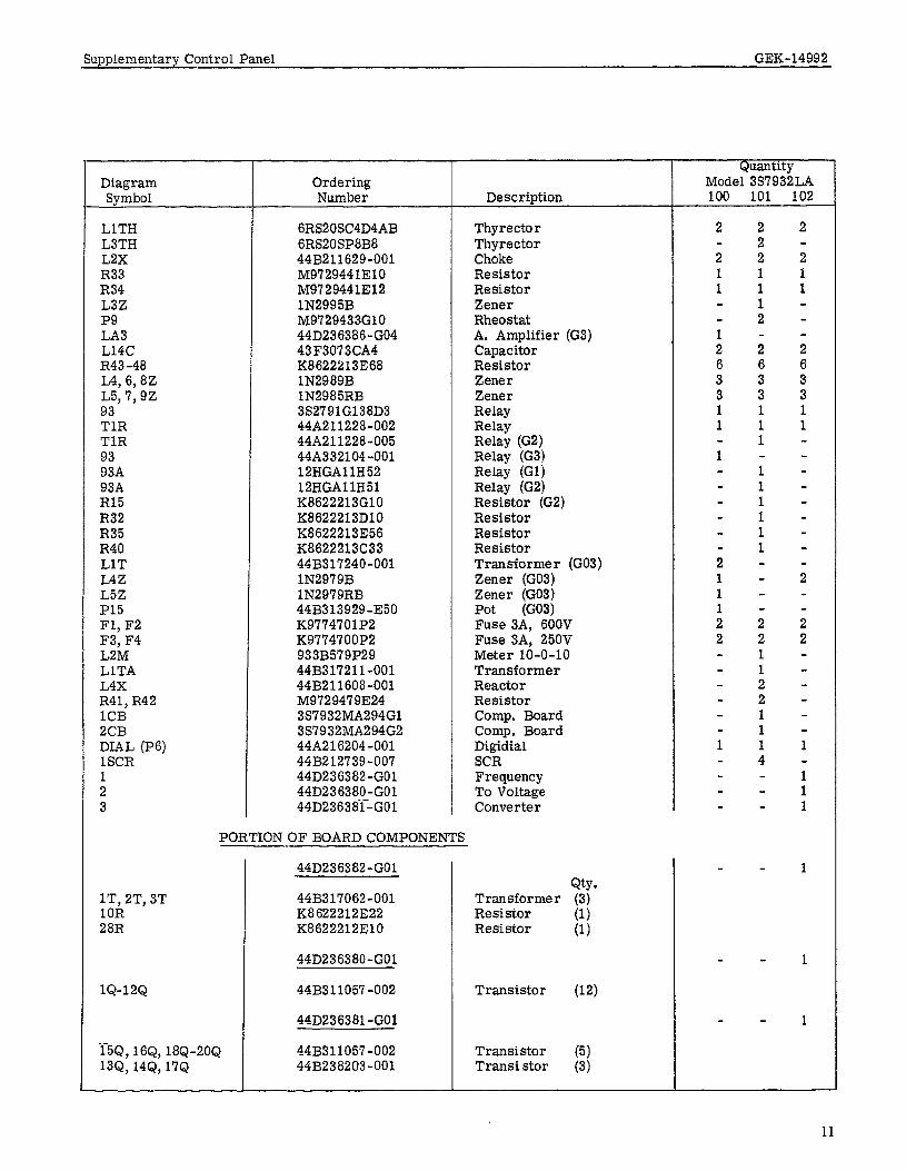
RENEWAL PARTS When ordering renewal parts, address the nearest General Electric Sales Office, specify the quantity required and give the rating and catalog numbers or describe the required parts in detail. In addition, give the 3s num- ber and complete nameplate data.
PRINCIPAL RENEWAL PARTS LIST
Diagram Symbol
LT2 Comp. Board
LlC Pl-P5, P7, I’8 Pl-P5 P7, P8 P6 LA1 LA2 LA3 LA4 LAl, LA2 JOG LlM ON LlZ L2Z P14 P14 LlT LlTA lo-17REC
Ordering Number
44B317107-001 44C384427GOl 44C384427GO2 44C384427GO3 44C384427GO4 44B312446-550 44B313929-610 44A335863 -GlO 44A335R61 -F25 K9770328H50 44D236386-GO1 44D331902-GO1 44D236386-GO2 44D236386-GO3 44D331903-(302, GO3 CRlOIDNlCl 44B313992-002 327 lN2823B lN2819RB M9729433F50 M9729433GlO 44B317098-001 44B317211-001 44B232019-005
Description
Transformer Filter Board Filter Board Filter Board (G2) Filter Board (G3) Capacitor Rheostat Rheostat (G2) Rheostat Potentiometer A. Amplifier (Gl, G2) A. Amplifier (Gl, G2) A. Amplifier (Gl, G2) A. Amplifier A. Amplifier (G3) Pushbutton Meter Relay Lamp Zener Zgner Rheostat Rheostat Transformer Transformer Rectifier
Quantity Model 3S7932LAA
100 101 102 103
1 1
1 1 1 1 1 1
f 3 1 1 1
2
8
1 1
1
1 1 8 7
2
8
1
1
5 2 1
1 1 1
1”
1” 1 1
1 1 10
10
Supplementary Control Panel GEK-14992
Diagram Symbol
LlTH LSTH L2X R33 R34 L3Z PQ LA3 L14C R43-48 L4, 6,8Z L5,7, QZ 93 TlR TlR 93 Q3A 93A R15 R32 R35 R40 LlT L4Z L5Z P15 Fl, F2 F3, F4 L2M LlTA L4X R41, R42 1CB 2CB DIAL (P6) 1SCR 1 2 3
lT, 2T, 3T 10R 28R
IQ-12Q
Ordering Number
6RS20SC4D4AB 6RS20SP8B8 44B21162Q-001 M9729441310 MQ729441312 lN2QQ5B MQ’729433GlO 44D236386-GO4 43F3073CA4 K8622213368 lN298QB lN2985RB 3527QlG138D3 44A211228-002 44A211228-005 448332104 -001 12HGAllH52 12HGAllH51 K8622213GlO IS86222131310 K8622213356 K8622213C33 44B317240-001 lN297QB lN297QRB 44B313929-350 KQ774701P2 KQ774700P2 Q33B57QP2Q 44B317211-001 44B211608-001 M972947QE24 3S7932MA294Gl 3S7932MA294G2 44A216204-001 44B212739-007 44D236382-GO1 441)236380-GO1 44D236381--GO1
PORTION OF BOARD COMPONENTS
Description
Thyrecto r Thyrector Choke Resistor Resistor Zener Rheostat A. Amplifier (G3) Capacitor Resistor Zener Zener Relay Relay Relay (G2) Relay (G3) Relay (Gl) Relay (G2) Resistor (G2) Resistor Resistor Resistor Transformer (G03) Zener (G03) Zener (GO3) Pot (GO3) Fuse 3A, 600V Fuse 3A, 250V Meter lo-O-10 Transformer React0 r Resistor Comp. Board Comp. Board Digidial SCR Frequency To Voltage Converter
l-5Q, 16Q, 18Q-20Q 13Q, 14Q, 17Q
44D236382-GO1
44B317062-001 K.8622212322 K8622212ElO
440236380-GO1
44B311057-002
44D236381 -GO1
44B31105’7-002 44B238203 -001
Qty. Transformer (3) Resistor Resistor I:;
Transistor (12)
Transistor (5) Transi stor (3)
Quantity Model 3S7932LA 100 101 102
1 1 1 1 1 1
2 2 1
; 2 1 1 1 4
2
2 2
1
1 1 1
1
1
1
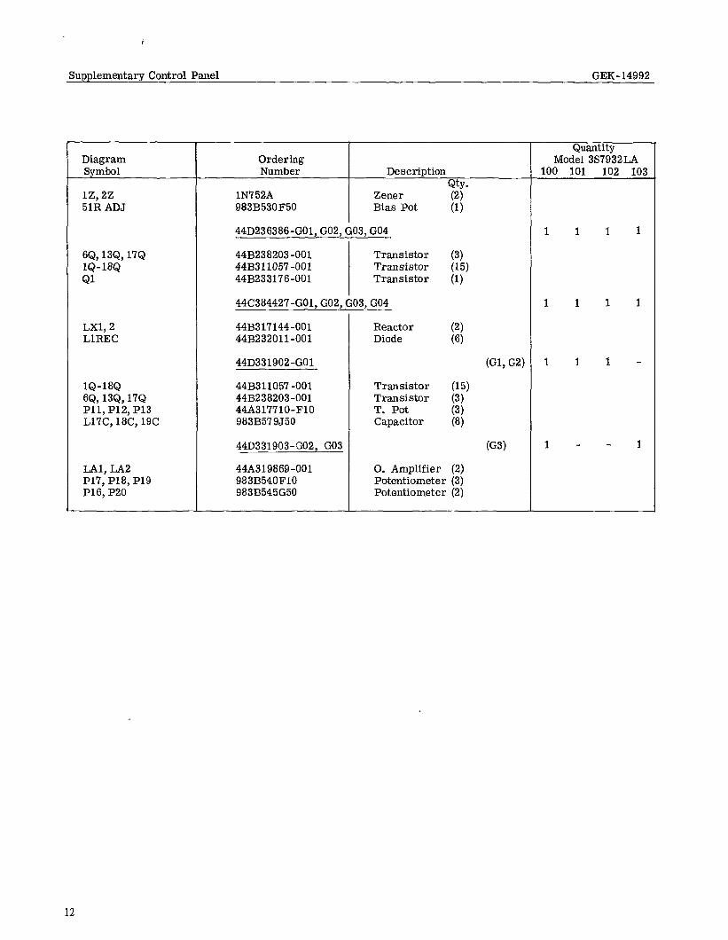
Supplem.entary Control Panel GEK-14992
Diagram Symbol
lZ, 22 51R ADJ
‘3Q, 13Q, 17Q IQ-18Q Ql
LXl, 2 LlREC
IQ-18Q SQ, 13Q, 17Q Pll, P12, P13 L17C, 18C, 19C
LAl, LA2 P17, P18, P19 P16, P20
Quantity Ordering Model 3S7932LA Number Description 100 101 102 103
Qty. lN7 52A Zener 983B530F50 Bias Pot ;;
44D236386-601, G02, G03, GO4 1 1 1 1
44B238203-001 Transistor (3) 44B311057 -001 Transistor 44B233176-001 Transistor I:,“’
44C384427-(302, G02, G03, GO4 1 1 1 1
44B317144-001 Reactor 44B232011-001 Diode g
44D331902-GO1 (Gl, G2) 1 1 1 -
44B311057-001 Transistor (15) 44B238203 -001 Transistor (3) 44A317710-FlO T. Pot 983B579J50 Capacitor ii;
44D331903-G02, GO3 (G3) 1 - - 1
44A319869-001 0. Amplifier (2) 983B540FlO Potentiometer (3) 983B545G50 Potentiometer (2)
12
TO
TUR
BIN
E 3d
TA
CH
OM
ETER
20
VO
LTS
PE
R
1000
R
PM
l----
----
-_--
--
--.A
’ C
ON
NEC
T TO
TR
ANSr
UR
E_CI
)
I TJ
KI
L ,
TER
MIN
ALS
1,2.
3 AT
-1
Ls
I
3600
RP
M
(I80
HZ)
4,5,
6
AT
IBO
O R
PM
I ---
-.
w,t,
, Fr
eque
ncy
AMPL
IFIE
R
InpI
t R
Epla
ce
With
Fl
c3ne
3.
C
CFI
NEC
TIO
NS
A-
30”(+
?Ai-
LIM
IT(--
I E-
G
ND
. &
”
(+I
C-
22Vk
) C
[-LO
ADW
6~
DE-
CH
OPP
ER
DC
-INPU
T
K,(T
S).M
&.W
F-
O
UTP
UT
ELG
AIN
(P6)
I fT
5 ItT
jS
I +T
$ 44
C30
1681
D
IAG
RAM
TIM
E C
ON
STAN
TAN
T PO
T FU
NC
TIO
N
- -
.,-50
SE
CO
ND
S PI
-
TI
2-1.
5 ,,
PP.
- T3
.0
2-
I I(
P3
- T3
.2-l
5 I.
P4
- T4
.0
2-
.I .,
P5
- T5
2-
100
GAIN
/P
6)
- K,
(1
0)
(TUR
N)
P7
- 80
05T
LIM
ITA~
JuST
P
B
- BU
CK
” I
AMPL
IFIE
R
CO
NN
ECTI
ON
S
LA3
.A-
3OV
7-T
4 E;
E-
GN
D
d-T5
c-
22
v d-
INPU
T D
E-C
HO
PPER
F-
O
UTP
UT
44C
3016
80
DIA
GR
AM
1 1
z-
TO
SH
2,
“3
AMPL
IFIE
R
CO
NN
ECTI
ON
S A
MP
LlFl
ER
t.
ION
&&!
L&
,A-
JO”+
A’
TI-S
--55S
EC.
A-30
VM)
+2(2
) E,
E-G
NO
B’
-TI-7
5-63
SEC
B;
B-G
ND
. c-
ZPV-
&T
I- l-l
15
SEC
. c-
22
V(-
1 C
,-T3
D,-
INPU
T D
E-C
HO
PPER
INPU
T D
/-IN
PUT
DE-
CH
OPP
ER
E-
T-Z(
l) F-
OU
TPU
T F-
O
UTP
UT
44C
30
I679
D
IAG
RAM
44
C30
1644
D
IAG
RAM
NOTE
VA
LUE
S
FOR
.L17
C,L
l8C
,LIS
C,
PIIP
lZ,P
l3AR
E SH
OW
N
NO
MIN
AL
FOR
3600
R
PM
GEN
ERAT
OR
S.
CAP
ACIT
OR
V
ALU
ES
W
ILL
LJO
UBL
E O
N 18
00 R
PM G
ENER
ATO
RS
CIR
CU
ITS
WIL
L B
E F
ACTO
RY
ADJU
STED
FO
R 60
C
YCLE
O
R 30
C
YCLE
O
N 36
00
RPM
O
R 18
00
RPM
G
ENER
ATO
RS
RES
PEC
TIVE
LY
TYPI
CAL
ELEM
ENTA
RY
DIAG
RAM
OF
3S
9932
LAlO
O SU
PPLE
MEN
TARY
CO
NTRO
L PA
NEL
Figu
re
2 (S
heet
1
of
2)
TO
SKI
r ---
- ---
-----
----
-----
I I
1 JO
Y +
TOSH
’
‘d I”n
I .5
M
E’
, IR
ZJf-
I0d-
L
I 6O
cy
‘3 -
L---
-ur
- - eF
2:
- --
-700
47~j-
125v
DC
@
NOTE
S RE
MOT
E M
ETER
M
AY
BE
ADDE
D IN
PA
RALL
EL
WIT
H O
UT-
PUT
( TE
RMIN
ALS
L6-L
6.l
2000
O
HMS/
VOG
T M
,N
(L-)
TE
RMIN
ALS
ON
SUPP
LEM
ENTA
RY
PANE
L FO
R EX
TERN
AL
CONN
ECTI
ON
0 M
AGNE
TIC
AMPL
lFlE
P,
BOO
ST.
BUCK
-100
TU
RN;
EACH
(?
PE
Iv3
ffE
G“‘4
’-0K)
0
MET
ER
RELA
Y W
ITH
ALAR
M
CONT
ACTS
TY
PE
1951
(LIM
)
n RE
MOT
E CN
OT
FURN
INSH
ED
WIT
H S
CONT
ROL)
(
0 TE
RMIN
ALS
ON
COM
PONE
NT
BOAR
D (&
ID
2363
63-G
o,\
IA
RANG
E O
F P6
I-5
0 W
ITH
JUM
PER
IN
PLAC
E ’
16
RANG
E O
F P6
50
-100
W
ITH
JUM
PER
REM
OVED
2 JU
MPE
R M
AINT
AIN
IN
HORI
ZONT
AL
POS,
T,oN
TYPI
CAL
ELEM
ENTA
RY
DIAG
RAM
OF
3S
7932
LAlO
O SU
PPLE
MEN
TARY
CO
KTRO
L PA
NEL
Figu
re
2 (S
heet
2
of
2)
Supplementary Control Panel GEK-14992
I
t
t
i
i ,
15
. Supplementary Control Panel GEK-14992
16
2-74 (500)
DRIVE SYSTEMS PRODUCT DEPARTMENT GENERAL ELECTRIC COMPANY, WAYNESBORO, VIRGINIA 22980