Embed Size (px)
Citation preview
Power System Protection
Dr. Ibrahim El-Amin
Protective Device Coordination
Definition
Overcurrent Coordination A systematic study of current responsive devices
in an electrical power system.
Objective
To determine the ratings and settings of fuses, breakers, relay, etc.
To isolate the fault or overloads.
Criteria Economics
Available Measures of Fault
Operating Practices
Previous Experience

Design Open only PD upstream of the fault or overload Provide satisfactory protection for overloads Interrupt SC as rapidly (instantaneously) as
possible Comply with all applicable standards and codes Plot the Time Current Characteristics of
different PDs

AnalysisWhen:
New electrical systems
Plant electrical system expansion/retrofits
Coordination failure in an existing plant
Protection vs. Coordination Coordination is not an exact science Compromise between protection and
coordination Reliability Speed Performance Economics Simplicity

Protection Prevent injury to personnel
Minimize damage to components
Quickly isolate the affected portion of the system
Minimize the magnitude of available short-circuit
Spectrum Of Currents Load Current
Up to 100% of full-load 115-125% (mild overload)
Overcurrent Abnormal loading condition (Locked-Rotor)
Fault Current Fault condition Ten times the full-load current and higher
Coordination
Limit the extend and duration of service interruption
Selective fault isolation
Provide alternate circuits
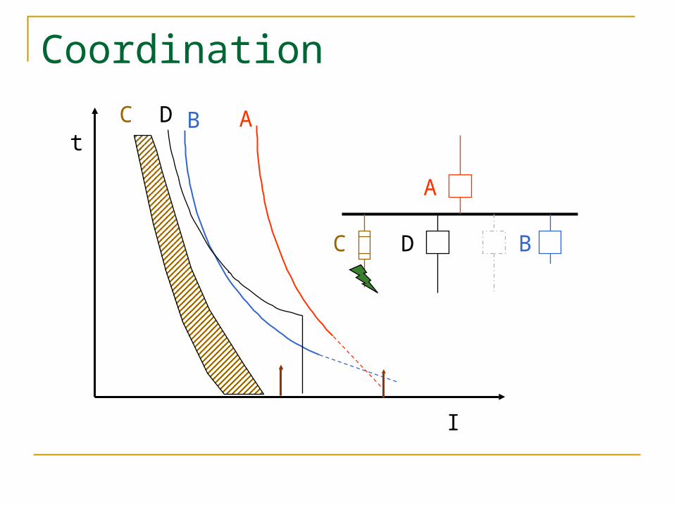
Coordination
t
I
C B A
C
D
D B
A
Equipment Motor
Transformer
Generator
Cable
Busway
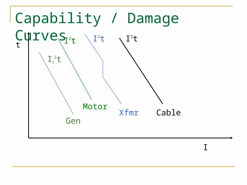
Capability / Damage Curvest
I
I22t
Gen
I2t
MotorXfmr
I2t
Cable
I2t

Transformer CategoryANSI/IEEE C-57.109
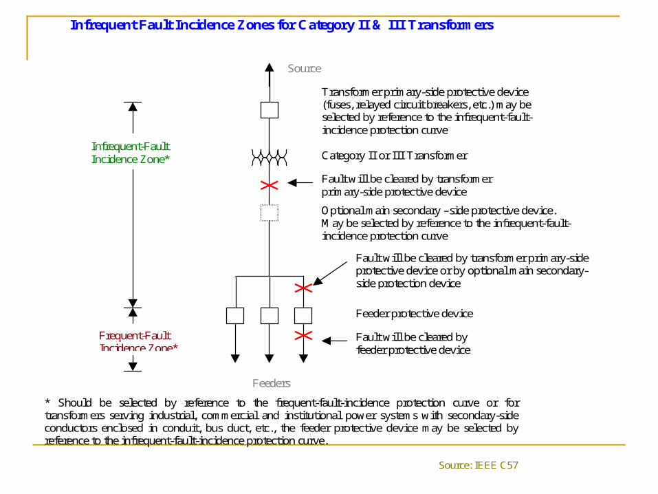
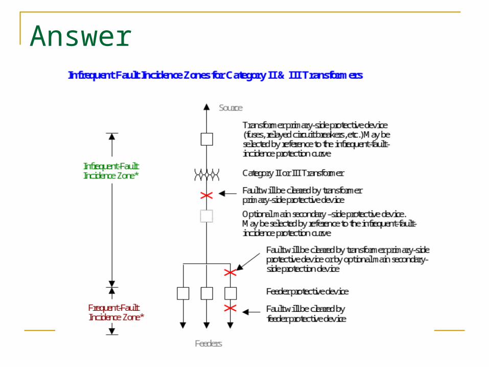
Infrequent Fault Incidence Zones for Category II & III Transformers
* Should be selected by reference to the frequent-fault-incidence protection curve or for transformers serving industrial, commercial and institutional power systems with secondary-side conductors enclosed in conduit, bus duct, etc., the feeder protective device may be selected by reference to the infrequent-fault-incidence protection curve.
Source: IEEE C57
Source
Transformer primary-side protective device (fuses, relayed circuit breakers, etc.) may be selected by reference to the infrequent-fault-incidence protection curve
Category II or III Transformer
Fault will be cleared by transformer primary-side protective device
Optional main secondary –side protective device. May be selected by reference to the infrequent-fault-incidence protection curve
Feeder protective device
Fault will be cleared by transformer primary-side protective device or by optional main secondary-side protection device
Fault will be cleared by feeder protective device
Infrequent-Fault Incidence Zone*
Feeders
Frequent-Fault Incidence Zone*
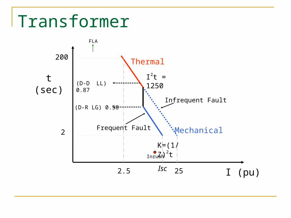
Transformer
t(sec)
I (pu)
Thermal200
2.5
I2t = 1250
2
25Isc
Mechanical
K=(1/Z)2t
(D-D LL) 0.87
(D-R LG) 0.58
Frequent Fault
Infrequent Fault
Inrush
FLA
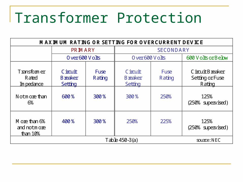
Transformer Protection
MAXIMUM RATING OR SETTING FOR OVERCURRENT DEVICE PRIMARY SECONDARY
Over 600 Volts Over 600 Volts 600 Volts or Below
Transformer Rated
Impedance
Circuit Breaker Setting
Fuse
Rating
Circuit Breaker Setting
Fuse
Rating
Circuit Breaker Setting or Fuse
Rating
Not more than 6%
600 %
300 %
300 %
250%
125%
(250% supervised)
More than 6% and not more
than 10%
400 %
300 %
250%
225%
125%
(250% supervised)
Table 450-3(a) source: NEC

Protective Devices Fuse
Relay (50/51 P, N, G, SG, 51V, 67, 46, 79, 21, …)
Thermal Magnetic
Low Voltage Solid State Trip
Electro-Mechanical
MCP
Overload Heater

Fuse Non Adjustable Device
Continuous and Interrupting Rating
Voltage Levels
Characteristic Curves Min. Melting
Total Clearing
Application

Minimum Melting Time Curve
Total Clearing Time Curve

Current Limiting Fuse(CLF)
Limits the peak current of short-circuit
Reduces magnetic stresses (mechanical damage)
Reduces thermal energy
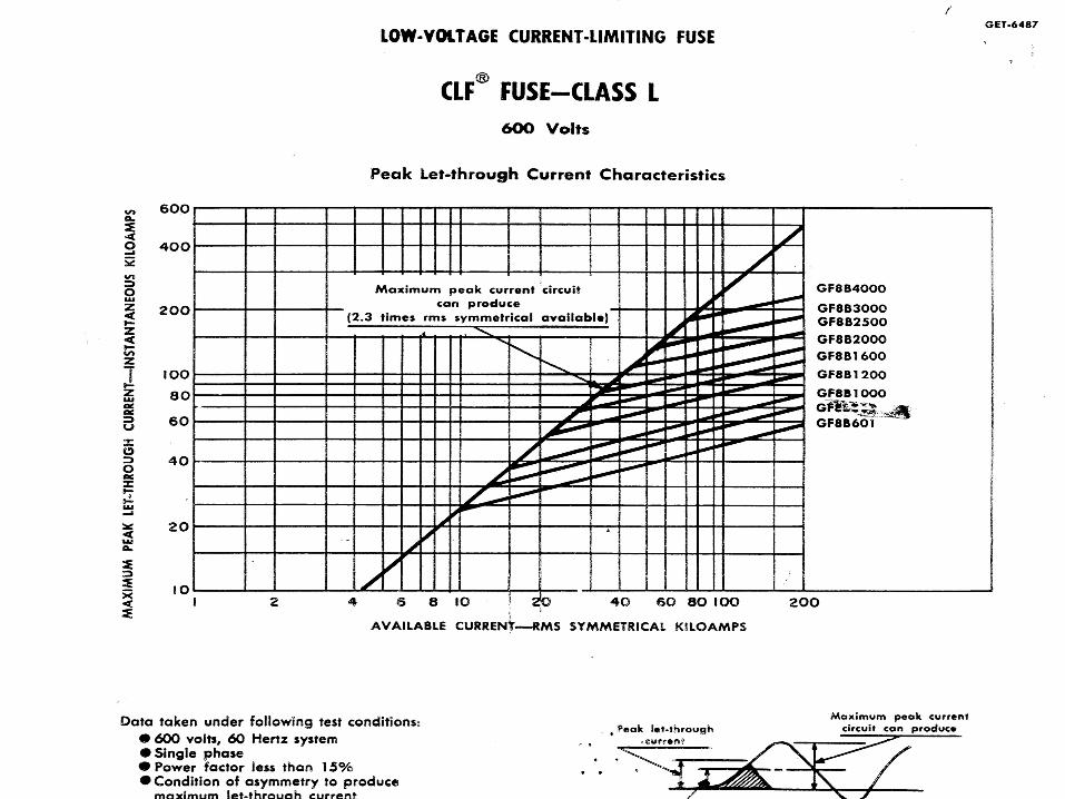
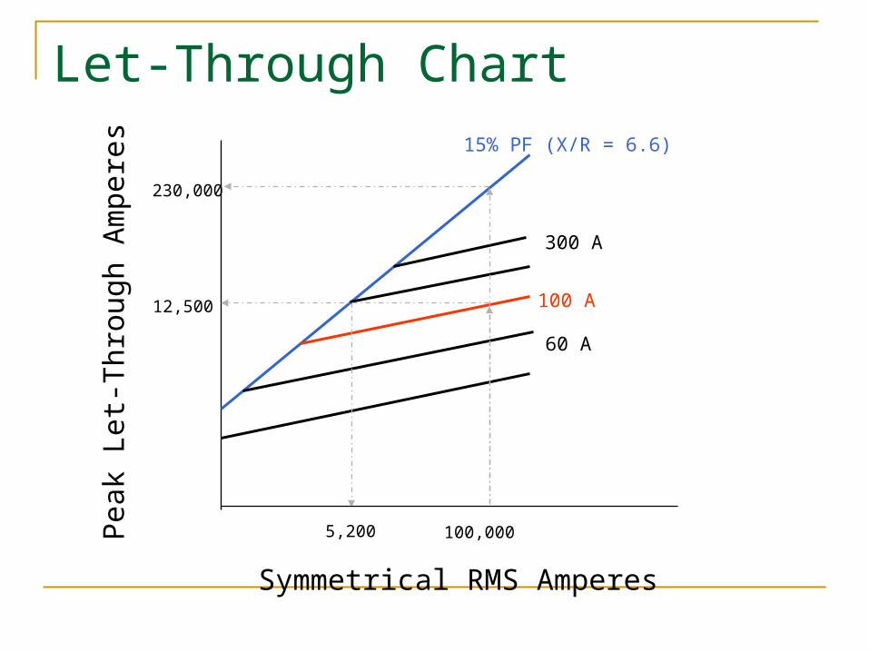
Symmetrical RMS Amperes
Pea
k Le
t-Thr
ough
Am
pere
s
100 A
60 A
15% PF (X/R = 6.6)
12,500
5,200
230,000
300 A
100,000
Let-Through Chart

FuseGenerally:
CLF is a better short-circuit protection Non-CLF (expulsion fuse) is a better Overload
protection
Selectivity Criteria
Typically: Non-CLF: 140% of full load CLF: 150% of full load
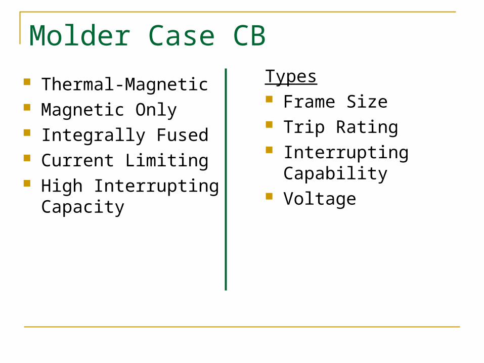
Molder Case CB Thermal-Magnetic Magnetic Only Integrally Fused Current Limiting High Interrupting
Capacity
Types Frame Size Trip Rating Interrupting Capability Voltage
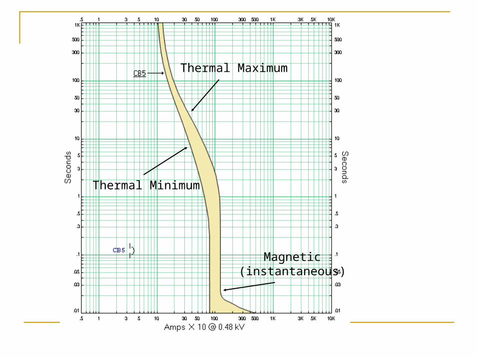
Thermal Minimum
Thermal Maximum
Magnetic(instantaneous)

LVPCB Voltage and Frequency Ratings
Continuous Current / Frame Size Override (12 times cont. current)
Interrupting Rating
Short-Time Rating (30 cycle)
Fairly Simple to Coordinate
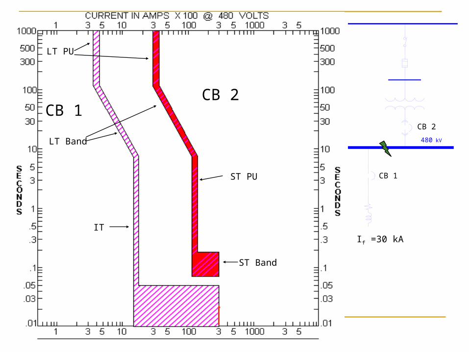
480 kV
CB 2
CB 1
CB 2CB 1
IT
ST PU
ST Band
LT PU
LT Band
If =30 kA

Motor Protection Motor Starting Curve
Thermal Protection
Locked Rotor Protection
Fault Protection
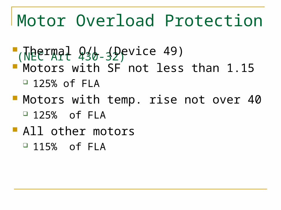
Motor Overload Protection (NEC Art 430-32)
Thermal O/L (Device 49) Motors with SF not less than 1.15
125% of FLA Motors with temp. rise not over 40
125% of FLA All other motors
115% of FLA

Locked Rotor Protection
Thermal Locked Rotor (Device 51) Starting Time (TS < TLR) LRA
LRA sym LRA asym (1.5-1.6 x LRA sym) + 10% margin
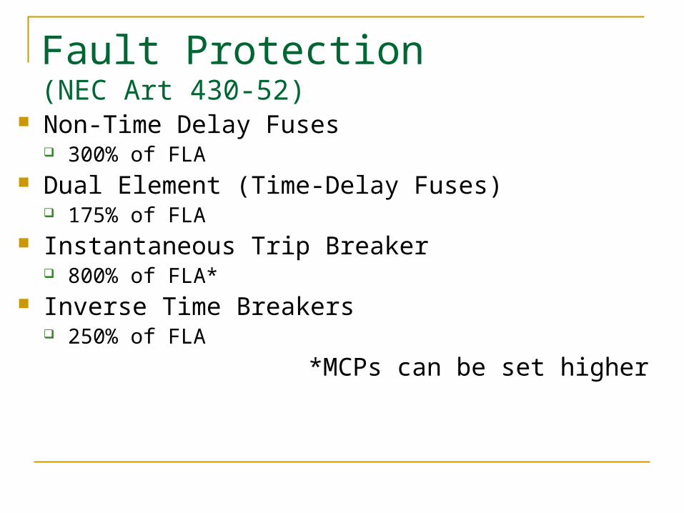
Fault Protection (NEC Art 430-52)
Non-Time Delay Fuses 300% of FLA
Dual Element (Time-Delay Fuses) 175% of FLA
Instantaneous Trip Breaker 800% of FLA*
Inverse Time Breakers 250% of FLA
*MCPs can be set higher

200 HP
MCPO/L
Starting Curve
I2T(49)
MCP (50)
(51)ts
tLR
LRAs LRAasym
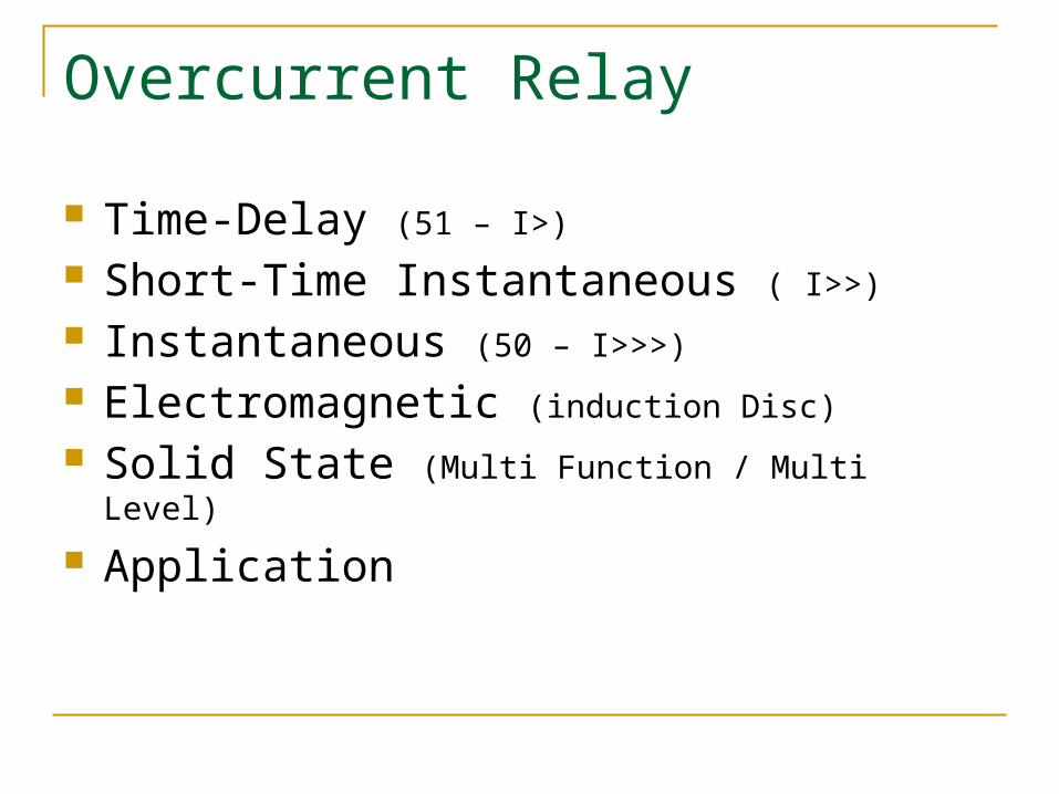
Overcurrent Relay
Time-Delay (51 – I>) Short-Time Instantaneous ( I>>) Instantaneous (50 – I>>>) Electromagnetic (induction Disc) Solid State (Multi Function / Multi Level)
Application

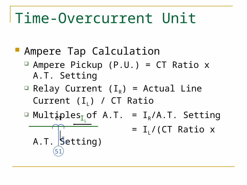
Time-Overcurrent Unit
Ampere Tap Calculation Ampere Pickup (P.U.) = CT Ratio x A.T. Setting Relay Current (IR) = Actual Line Current (IL) / CT
Ratio Multiples of A.T. = IR/A.T. Setting
= IL/(CT Ratio x A.T. Setting)
IL
IR
CT
51

Instantaneous Unit
Instantaneous Calculation Ampere Pickup (P.U.) = CT Ratio x IT Setting Relay Current (IR) = Actual Line Current (IL) / CT
Ratio Multiples of IT = IR/IT Setting
= IL/(CT Ratio x IT Setting)
IL
IR
CT
50
41
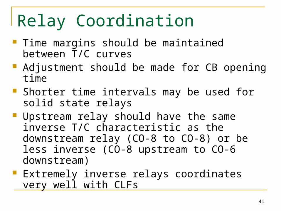
Relay Coordination Time margins should be maintained between T/C
curves Adjustment should be made for CB opening time Shorter time intervals may be used for solid state
relays Upstream relay should have the same inverse T/C
characteristic as the downstream relay (CO-8 to CO-8) or be less inverse (CO-8 upstream to CO-6 downstream)
Extremely inverse relays coordinates very well with CLFs

Fixed Points
Motor starting curves Transformer damage curves & inrush
points Cable damage curves SC maximum fault points Cable ampacities
Points or curves which do not change regardless of protective device settings:
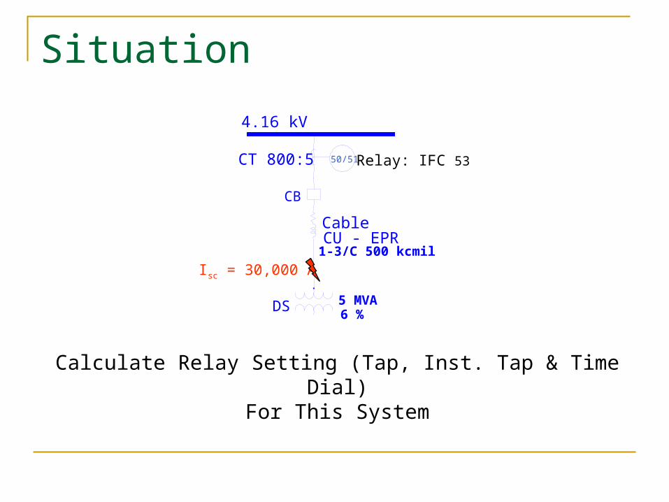
Situation
Calculate Relay Setting (Tap, Inst. Tap & Time Dial)For This System
4.16 kV
DS 5 MVA
Cable
1-3/C 500 kcmilCU - EPR
CB
Isc = 30,000 A
6 %
50/51 Relay: IFC 53CT 800:5

Solution
AInrsuh 328,869412I
A338.4800
5II LR
Transformer: AkV
kVAL 694
16.43000,5I
IL
CTRIR
Set Relay:
A 55 1.52800
5328,8)50(
1)38.1(6/4.338 0.6
4.5338.4%125
AInst
TDATAP
A

Question
What is ANSI Shift Curve?
Answer For delta-delta connected transformers, with
line-to-line faults on the secondary side, the curve must be reduced to 87% (shift to the left by a factor of 0.87)
For delta-wye connection, with single line-to-ground faults on the secondary side, the curve values must be reduced to 58% (shift to the left by a factor of 0.58)

Question
What is meant by Frequent andInfrequent for transformers?
Answer
QuestionWhat T/C Coordination interval should be
maintained between relays?

Answer
At
I
B
CB Opening Time
+
Induction Disc Overtravel (0.1 sec)
+
Safety margin (0.2 sec w/o Inst. & 0.1 sec w/ Inst.)

Question
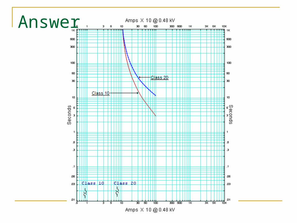
What is Class 10 and Class 20Thermal OLR curves?

Answer
Class 10 for fast trip, 10 seconds or less Class 20 for, 20 seconds or less There is also a Class 30 for long trip time
Answer


![Foldable %20 compromises%20and%20events%20that%20led%20to%20the%20civil%20power%20point[1]](https://img.pdfslide.us/doc/110x75/55d55a6cbb61ebff4c8b45c7/foldable-20-compromises20and20events20that20led20to20the20civil20power20point1.jpg)


![Eddy-900001 A181Actividad%20ingles%20power%20point[1]](https://img.pdfslide.us/doc/110x75/58865b4c1a28ab26598b5e1f/eddy-900001-a181actividad20ingles20power20point1.jpg)